EP3051674B1 - Squirrel-cage rotor for an asynchronous motor - Google Patents
Squirrel-cage rotor for an asynchronous motor Download PDFInfo
- Publication number
- EP3051674B1 EP3051674B1 EP15305088.5A EP15305088A EP3051674B1 EP 3051674 B1 EP3051674 B1 EP 3051674B1 EP 15305088 A EP15305088 A EP 15305088A EP 3051674 B1 EP3051674 B1 EP 3051674B1
- Authority
- EP
- European Patent Office
- Prior art keywords
- rotor
- bar
- section
- magnetic mass
- small base
- Prior art date
- Legal status (The legal status is an assumption and is not a legal conclusion. Google has not performed a legal analysis and makes no representation as to the accuracy of the status listed.)
- Active
Links
Images
Classifications
-
- H—ELECTRICITY
- H02—GENERATION; CONVERSION OR DISTRIBUTION OF ELECTRIC POWER
- H02K—DYNAMO-ELECTRIC MACHINES
- H02K3/00—Details of windings
- H02K3/46—Fastening of windings on the stator or rotor structure
- H02K3/48—Fastening of windings on the stator or rotor structure in slots
-
- H02K17/165—
-
- H—ELECTRICITY
- H02—GENERATION; CONVERSION OR DISTRIBUTION OF ELECTRIC POWER
- H02K—DYNAMO-ELECTRIC MACHINES
- H02K1/00—Details of the magnetic circuit
- H02K1/06—Details of the magnetic circuit characterised by the shape, form or construction
- H02K1/22—Rotating parts of the magnetic circuit
- H02K1/28—Means for mounting or fastening rotating magnetic parts on to, or to, the rotor structures
-
- H—ELECTRICITY
- H02—GENERATION; CONVERSION OR DISTRIBUTION OF ELECTRIC POWER
- H02K—DYNAMO-ELECTRIC MACHINES
- H02K17/00—Asynchronous induction motors; Asynchronous induction generators
- H02K17/02—Asynchronous induction motors
- H02K17/16—Asynchronous induction motors having rotors with internally short-circuited windings, e.g. cage rotors
- H02K17/20—Asynchronous induction motors having rotors with internally short-circuited windings, e.g. cage rotors having deep-bar rotors
Definitions
- the present invention relates to a high-power electric motor rotor intended to operate at particularly high rotation speeds.
- the invention applies to asynchronous motors capable of operating at high peripheral speeds, typically from 100 ms -1 , motors in particular intended for gas and oil applications, whether on land, at sea or even underwater.
- the peripheral speed is the tangential speed calculated at the outer diameter of the rotating rotor.
- High-power electric motors capable of operating at high rotational speeds have many applications.
- manufacture of motors meeting increasing requirements in terms of power and speed imposes new constraints, particularly mechanical, on the rotor of said motors.
- Patent documents EP 0 608 675 A1 And US 5,512,792 describe particularly effective embodiments of rotors for asynchronous electric motors, operating at high power and speeds. A rotor is thus described whose bars constituting the squirrel cage can freely expand, thus making it possible to attenuate the effects due to thermal imbalances.
- the patent document FR 2 950 751 proposes a rotor capable of being integrated into an electric motor with improved characteristics in terms of supported power and peripheral rotation speed, in particular by its capacity to convey greater electrical power through the squirrel cage of the rotor.
- the rotor comprises a plurality of electrical conductors, each conductor being formed by the assembly of a main bar and a secondary bar respectively having a substantially circular section and passing through the magnetic mass of the rotor via a notch.
- the shape and arrangement of each notch are defined so as to ensure sufficient contact between the main bar and the secondary bar to allow the passage of an electric current when the rotor is rotating.
- the document FROM 1488684 discloses a squirrel cage rotor comprising single bars having over their entire length a trapezoidal section forming an isosceles trapezoid and in which the small base of each bar is disposed radially outwardly relative to the rotor axis.
- the invention therefore aims to overcome these problems by proposing an improved rotor.
- the present invention relates in particular to a rotor for an electric motor according to claim 1.
- the invention also relates to a motor capable of driving the rotor as defined above at a peripheral speed greater than or equal to 100 m.s-1 at the level of the external diameter of the magnetic mass.
- the present invention also has the advantage that it makes it possible to significantly improve the power supported by engines such as those described in the patent documents.
- EP 0 608 675 And US 5,512,792 without causing any major changes to the structure of existing rotors.
- the rotor according to the invention finds application in motors capable of operating at high peripheral speeds typically from 100 ms -1 .
- the rotor according to the invention is in particular suitable for use in asynchronous electric motors, in particular intended for gas and oil applications, whether on land, at sea, or even underwater.
- the expression "substantially equal to” will express a relationship of equality to plus or minus 10%, preferably a relationship of equality to plus or minus 5%.
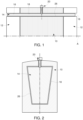
- FIG. 1 shows a longitudinal half-section of a rotor according to a first embodiment, as well as its axis A of rotation.
- the rotor thus represented is adapted to cooperate with a stator and shafts (not shown in the figure 1 ).
- the rotor comprises a magnetic mass 10 enclosed on either side by short-circuit rings 12.
- the magnetic mass 10 results from the assembly of magnetic sheets, the production of which, in particular the means for clamping said sheets together, is described in particular in the patent document US 5,512,792 .
- the rotor comprises a plurality of electrical conductors capable of conducting, through the magnetic mass 10, electrical currents applied to the rotor by the short-circuit rings 12.
- Each electrical conductor consists of a single bar 14.
- each bar 14 is constant or substantially constant over its entire length.
- the section of each bar is trapezoidal in shape. More precisely, the section of each bar 14 is an isosceles trapezoid having a small base and a large base.
- the 14 bars came from material. They are made of copper or copper alloy.
- the short-circuit rings 12 together with the bars 14 form the squirrel cage of the rotor.
- each bar 14 is freely arranged in orifices 16 provided on the periphery of the short-circuit rings 12.
- Each orifice 16 has a section whose shape is complementary to that of the section of the bar 14 that it accommodates, but with slightly larger internal dimensions so that there is a tolerance clearance. This in particular allows the free expansion of the end of the bar 14 in the orifice 16.
- the orifices 16 can be produced by milling or broaching the short-circuit ring 12.
- each bar 14 is received inside a notch 18 made in the magnetic mass.
- Each notch 18 has a section whose shape is complementary to that of the section of the bar 14 which it accommodates, but with slightly larger internal dimensions so that there is a tolerance clearance.
- This tolerance clearance referenced by the number 26 on the figure 2 , ensures the free expansion of the bar 14 in the notch 18 of the magnetic mass 10.
- the bars 14 are fixed to the magnetic mass 10 at a single point using any suitable fixing means 20, such as for example a screw, a pin or by any device, method and fixing accessory, thus allowing a balanced distribution of longitudinal thermal expansion for substantially equal relative movements between the ends of the bar 14 and the short-circuit rings 12.
- any suitable fixing means 20 such as for example a screw, a pin or by any device, method and fixing accessory, thus allowing a balanced distribution of longitudinal thermal expansion for substantially equal relative movements between the ends of the bar 14 and the short-circuit rings 12.
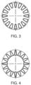
- each bar 14 is arranged so that its large base is oriented radially outwards relative to the axis A of rotation of the rotor.
- the notches 18 and the orifices 16 have a suitable trapezoidal shape.
- the transverse dimensions of the bar 14 are chosen so that the distance between one face of a bar and the face located opposite the neighboring bar is substantially constant.
- one face of a bar and the face located opposite the neighboring bar are parallel to each other, which makes it possible to increase the section of the bars 14 for the same magnetic mass 10, thus allowing an increase in the power of the motor having such a rotor.
- each bar 14 is arranged so that its small base is oriented radially outwards relative to the axis A of rotation of the rotor.
- the notches 18 and the orifices 16 have a suitable trapezoidal shape.
- the support surface of the bar 14 on the notch 18 being smaller than in the first embodiment, the forces at the contact points are greater and risk reducing the service life of the magnetic mass.
- the rotor when the rotor is rotating, it is the small base of the bar 14 which, under the effect of the centrifugal force, accentuates its support on the notch 18 and the orifices 16.
- the four corners of the trapezoidal section are provided with a rounding, of substantially equal value for the corners of the large base and of another substantially equal value for the corners of the small base. This makes it possible to reduce the concentrations of mechanical stress in the magnetic sheets of the magnetic mass 10 and in the short-circuit rings 12. This thus makes it possible to reduce the risk of magnetic saturation in the sheets of the magnetic mass 10 around the bars 14.
- the bar 14 has two rounded corners whose radius of the rounding is between 10% and 50% of the length of the large base and the small base respectively.
- the choice of the value of the radius of the rounding is a compromise between the reduction of mechanical constraints for example in the sheets of the magnetic mass 10 and the reduction of the section of the bars 14 useful for the passage of the electric current.
- the invention is particularly suitable for high-power motors operating at high rotation speeds, typically at peripheral speeds from 100 ms -1 .
- This type of motor is generally controlled by frequency variators. Starting the motor requires only a low electric current because of the applications for which these types of motors are intended, namely their use in compressors or pumps.
Landscapes
- Engineering & Computer Science (AREA)
- Power Engineering (AREA)
- Induction Machinery (AREA)
- Iron Core Of Rotating Electric Machines (AREA)
Description
La présente invention se rapporte à un rotor de moteur électrique de grande puissance destiné à fonctionner à des vitesses de rotation particulièrement élevées. En particulier, l'invention s'applique aux moteurs asynchrones aptes à fonctionner à des vitesses périphériques élevées typiquement à partir de 100 m.s-1, moteurs notamment destinés aux applications gazières, pétrolières, qu'elles soient sur terre, en mer, ou encore sous-marine.The present invention relates to a high-power electric motor rotor intended to operate at particularly high rotation speeds. In particular, the invention applies to asynchronous motors capable of operating at high peripheral speeds, typically from 100 ms -1 , motors in particular intended for gas and oil applications, whether on land, at sea or even underwater.
La vitesse périphérique est la vitesse tangentielle calculée au niveau du diamètre extérieur du rotor de rotation.The peripheral speed is the tangential speed calculated at the outer diameter of the rotating rotor.
Les moteurs électriques de forte puissance apte à fonctionner à des vitesses de rotations élevées trouvent de nombreuses applications. La fabrication de moteurs répondant à des exigences grandissantes en matière de puissance et de vitesse impose de nouvelles contraintes, notamment mécaniques, au niveau du rotor desdits moteurs. Les documents de brevet
Néanmoins, afin d'accroître encore la puissance reçue par ce type de moteur, l'augmentation du diamètre des barres constituant la cage d'écureuil s'avère nécessaire pour éviter l'échauffement excessif de ces dernières. Or, sur la base des exemples décrits dans les brevets cités précédemment, l'augmentation des sections desdites barres se traduit par une réduction des distances entre ces mêmes barres. Cette solution s'avère donc peu satisfaisante puisque la réduction de l'espacement entre chaque barre introduit de nouvelles contraintes magnétiques et mécaniques, ce qui aboutit, in fine, à fragiliser le rotor.However, in order to further increase the power received by this type of motor, increasing the diameter of the bars constituting the squirrel cage proves necessary to avoid excessive heating of the latter. However, on the basis of the examples described in the patents cited above, increasing the sections of said bars results in a reduction in the distances between these same bars. This solution therefore proves to be unsatisfactory since reducing the spacing between each bar introduces new magnetic and mechanical constraints, which ultimately results in weakening the rotor.
Le document de brevet
Cependant, un tel assemblage conduit à des difficultés de mise en oeuvre. En particulier, tant que la température de fonctionnement n'est pas stabilisée, des déformations différentielles entre la barre principale et la barre secondaire conduisent, d'une part, à l'existence d'un balourd et, d'autre part, à un mauvais contact électrique entre la barre principale et la basse secondaire.However, such an assembly leads to implementation difficulties. In particular, as long as the operating temperature is not stabilized, differential deformations between the main bar and the secondary bar lead, on the one hand, to the existence of an unbalance and, on the other hand, to poor electrical contact between the main bar and the secondary bar.
Le document
L'invention a donc pour but de palier à ces problèmes en proposant un rotor amélioré.The invention therefore aims to overcome these problems by proposing an improved rotor.
La présente invention a notamment pour objet un rotor pour moteur électrique selon la revendication 1.The present invention relates in particular to a rotor for an electric motor according to claim 1.
Suivant des modes particuliers de réalisation, le rotor comporte l'une ou plusieurs des caractéristiques suivantes :
- chaque barre est venue de matière et est réalisée en cuivre ou en un alliage de cuivre ;
- la section de chaque barre est sensiblement constante selon l'axe du rotor.
- each bar comes from material and is made of copper or a copper alloy;
- the section of each bar is substantially constant along the axis of the rotor.
L'invention a également pour objet un moteur apte à entraîner le rotor tel que défini ci-dessus à une vitesse périphérique supérieure ou égale à 100 m.s-1 au niveau du diamètre extérieur de la masse magnétique.The invention also relates to a motor capable of driving the rotor as defined above at a peripheral speed greater than or equal to 100 m.s-1 at the level of the external diameter of the magnetic mass.
La présente invention a encore pour avantage qu'elle permet d'améliorer significativement la puissance supportée par des moteurs tels que ceux décrit dans les documents de brevet
D'autres caractéristiques et avantages de la présente invention apparaîtront plus clairement à la lecture de la description qui suit, d'un exemple de réalisation particulier, donné à titre illustratif et nullement limitatif, et faite en se référant aux figures annexées qui représentent :
- la
figure 1 , une demi-coupe longitudinale d'un rotor ; - la
figure 2 , une vue agrandie d'une coupe transversale du rotor de lafigure 1 au voisinage d'une encoche ; - la
figure 3 , une coupe transversale d'un premier mode de réalisation du rotor au niveau de la masse magnétique de celui-ci ; et, - la
figure 4 , une coupe transversale d'un second mode de réalisation du rotor au niveau de la masse magnétique de celui-ci.
- there
figure 1 , a half longitudinal section of a rotor; - there
figure 2 , an enlarged view of a cross-section of the rotor of thefigure 1 near a notch; - there
figure 3 , a cross-section of a first embodiment of the rotor at the level of the magnetic mass thereof; and, - there
figure 4 , a cross-section of a second embodiment of the rotor at the level of the magnetic mass thereof.
Le rotor selon l'invention trouve pour application les moteurs aptes à fonctionner à des vitesses périphériques élevées typiquement à partir de 100 m.s-1. Le rotor selon l'invention est en particulier adapté à être utilisé au sein de moteurs électriques asynchrones, notamment destinés aux applications gazières, pétrolières, qu'elles soient sur terre, en mer, ou encore sous-marines. De façon conventionnelle dans la présente demande, l'expression « sensiblement égal à » exprimera une relation d'égalité à plus ou moins 10%, de préférence une relation d'égalité à plus ou moins 5%.The rotor according to the invention finds application in motors capable of operating at high peripheral speeds typically from 100 ms -1 . The rotor according to the invention is in particular suitable for use in asynchronous electric motors, in particular intended for gas and oil applications, whether on land, at sea, or even underwater. Conventionally in the present application, the expression "substantially equal to" will express a relationship of equality to plus or minus 10%, preferably a relationship of equality to plus or minus 5%.
La
Le rotor ainsi représenté est adapté à coopérer avec un stator et des arbres (non représentés sur la
Le rotor comporte une masse magnétique 10 enserrée de part et d'autre par des couronnes de court-circuit 12.The rotor comprises a
La masse magnétique 10 résulte de l'assemblage de tôles magnétiques dont la réalisation, en particulier les moyens de serrage desdites tôles entre elles, est décrite notamment dans le document de brevet
Le rotor comporte une pluralité de conducteurs électriques aptes à conduire, au travers de la masse magnétique 10, des courants électriques appliqués au rotor par les couronnes de court-circuit 12.The rotor comprises a plurality of electrical conductors capable of conducting, through the
Chaque conducteur électrique est constitué d'une unique barre 14.Each electrical conductor consists of a
De préférence, la section de chaque barre 14 est constante ou sensiblement constante sur la totalité de sa longueur.Preferably, the section of each
La section de chaque barre est de forme trapézoïdale. Plus précisément, la section de chaque barre 14 est un trapèze isocèle présentant une petite base et une grande base.The section of each bar is trapezoidal in shape. More precisely, the section of each
Les barres 14 sont venues de matière. Elles sont réalisées en cuivre ou alliage de cuivre.The 14 bars came from material. They are made of copper or copper alloy.
Les couronnes de court-circuit 12 ainsi que les barres 14 forment la cage d'écureuil du rotor.The short-
Les extrémités longitudinales de chaque barre 14 sont librement disposées dans des orifices 16 ménagés à la périphérie des couronnes de court-circuit 12.The longitudinal ends of each
Chaque orifice 16 a une section dont la forme est complémentaire de celle de la section de la barre 14 qu'il accueille, mais avec des dimensions intérieures légèrement supérieures de manière à ce qu'il existe un jeu de tolérance. Celui-ci permet notamment la libre dilatation de l'extrémité de la barre 14 dans l'orifice 16. Les orifices 16 peuvent être réalisés par fraisage ou brochage de la couronne de court-circuit 12.Each
Pour traverser la masse magnétique 10, chaque barre 14 est reçue à l'intérieur d'une encoche 18 ménagée dans la masse magnétique.To pass through the
Chaque encoche 18 a une section dont la forme est complémentaire de celle de la section de la barre 14 qu'il accueille, mais avec des dimensions intérieures légèrement supérieures de manière à ce qu'il existe un jeu de tolérance. Ce jeu de tolérance, référencé par le chiffre 26 sur la
Les barres 14 sont fixées à la masse magnétique 10 en un seul point à l'aide de tout moyen de fixation 20 adéquat, comme par exemple une vis, une goupille ou par n'importe quel dispositif, procédé et accessoire de fixation, permettant ainsi une répartition équilibrée de la dilatation thermique longitudinale pour des déplacements relatifs sensiblement égaux entre les extrémités de la barre 14 et les couronnes de court-circuit 12.The
Comme illustré sur la
Ainsi lorsque le rotor est en rotation, c'est la grande base de la barre 14 qui, sous l'effet de la force centrifuge, accentue son appui sur l'encoche 18 et les orifices 16.Thus when the rotor is rotating, it is the large base of the
De manière particulièrement avantageuse, les dimensions transversales de la barre 14 sont choisies pour que la distance entre une face d'une barre et la face située en vis-à-vis de la barre voisine, soit sensiblement constante. Dit autrement, une face d'une barre et la face située en vis-à-vis de la barre voisine sont parallèles entre elles, ce qui permet d'augmenter la section des barres 14 pour une même masse magnétique 10, donc de permettre une augmentation de puissance du moteur ayant un tel rotor.Particularly advantageously, the transverse dimensions of the
La
Cependant, dans le deuxième mode de réalisation, la surface d'appui de la barre 14 sur l'encoche 18 étant plus réduite que dans le premier mode de réalisation, les efforts aux points de contacts sont plus importants et risquent de réduire la durée de vie de la masse magnétique.However, in the second embodiment, the support surface of the
De plus, la distance entre deux barres successives n'étant pas sensiblement constante, des effets magnétiques non voulus et difficiles à contrôler sont générés, comme une saturation des lignes de flux magnétique et une induction excessive dans les tôles magnétiques de la masse magnétique 10, notamment au niveau de la grande base.In addition, since the distance between two successive bars is not substantially constant, unwanted and difficult to control magnetic effects are generated, such as saturation of the flux lines. magnetic and excessive induction in the magnetic sheets of the
Ainsi lorsque le rotor est en rotation, c'est la petite base de la barre 14 qui, sous l'effet de la force centrifuge, accentue son appui sur l'encoche 18 et les orifices 16. En variante, les quatre coins de la section trapézoïdale sont pourvus d'un arrondi, de valeur sensiblement égale pour les coins de la grande base et d'une autre valeur sensiblement égale pour les coins de la petite base. Ceci permet de réduire les concentrations de contrainte mécanique dans les tôles magnétiques de la masse magnétique 10 et dans les couronnes de court-circuit 12. Cela permet ainsi de réduire le risque de saturation magnétique dans les tôles de la masse magnétique 10 au pourtour des barres 14. Typiquement au moins la grande base, respectivement la petite base, de la barre 14 a deux coins arrondis dont le rayon de l'arrondi est compris entre 10% et 50% de la longueur respectivement de la grande base et de la petite base. Le choix de la valeur du rayon de l'arrondi est un compromis entre la réduction des contraintes mécaniques par exemple dans les tôles de la masse magnétique 10 et la réduction de la section des barres 14 utile pour le passage du courant électrique.Thus, when the rotor is rotating, it is the small base of the
L'invention est particulièrement adaptée aux moteurs de forte puissance évoluant à de grandes vitesses de rotation, typiquement à des vitesses périphériques à partir de 100 m.s-1. Ce type de moteur est généralement contrôlé par des variateurs de fréquence. Le démarrage du moteur ne nécessite qu'un faible courant électrique en raison des applications auxquelles sont destinés ces types de moteurs, à savoir leur utilisation dans des compresseurs ou des pompes.The invention is particularly suitable for high-power motors operating at high rotation speeds, typically at peripheral speeds from 100 ms -1 . This type of motor is generally controlled by frequency variators. Starting the motor requires only a low electric current because of the applications for which these types of motors are intended, namely their use in compressors or pumps.
Dans ce cas, une légère pression de la barre 14 dans l'orifice 16 suffit à permettre le passage d'un faible courant. Par ailleurs, pour les mêmes raisons, la section de la barre 14 assure à elle seule le passage du faible courant électrique au démarrage. Lorsque le moteur accroît sa vitesse, la force centrifuge devenant de plus en plus importante, cette dernière déforme la barre 14, qui va alors exercer une pression sur la face interne de l'orifice 16 dans les couronnes de court-circuit 12 et ainsi engendrer un contact plus important permettant un passage de courant électrique plus important dans les barres 14 et des barres 14 vers les couronnes de court-circuit 12.In this case, a slight pressure of the
L'homme du métier comprendra l'intérêt d'avoir des barres 14 fabriquées d'un seul tenant, et notamment d'une seule pièce à section de forme trapézoïdale, permettant d'accroître la section des barres 14 sur toute leur longueur y compris dans les orifices 16 des couronnes de court-circuit 12. Ceci permet d'augmenter à taille donnée la puissance d'un moteur électrique ayant un tel rotor, sans les inconvénients de balourd thermique suite à des dilatations thermiques différentielles dans des barres constituées d'au moins deux parties, ou d'étincelage entre les parties constituant la barre de section sensiblement trapézoïdale si elles ne sont pas au même potentiel électrique. Les techniques de passage de courant entre barres et couronnes de court-circuit ayant évolué, on peut comprendre l'avantage d'avoir aussi une section de forme sensiblement trapézoïdale dans les extrémités des barres 14 par un passage de courant électrique plus important dans les couronnes de court-circuit 12, augmentant par la même la puissance électrique d'un tel rotor.The person skilled in the art will understand the advantage of having
Claims (5)
- Rotor for electric motor including, on the rotor axis (A), a magnetic mass (10), gripped on either side by short-circuit rings (12), and having electrical conductors passing through it in a plurality of recesses (18), connecting the short-circuit rings (12) to form a squirrel cage, each electrical conductor consisting of a single bar (14) having, over the whole of the length thereof, a trapezoidal cross-section forming an isosceles trapezium, the small base of each bar (14) being disposed radially towards the outside with respect to the axis of the rotor (A), characterised in that the four corners of the trapezoidal cross section are provided with a round-off with a substantially equal value for the corners of the large base and another substantially equal value for the corners of the small base, the radius of the round-offs of the large base and the radius of the round-offs of the small base lying between 10% and 50% of the length respectively of the large base and of the small base.
- Rotor according to the preceding claim, wherein each bar (14) is made in one piece and is produced from copper or from a copper alloy.
- Rotor according to either one of the preceding claims, wherein the cross section of each bar is substantially constant along the axis of the rotor (A).
- Motor able to drive the rotor according to any one of the preceding claims at a peripheral speed greater than or equal to 100 m.s-1 at the outside diameter of the magnetic mass (10).
- Use of the rotor according to any one of the preceding claims, in a motor able to drive said rotor at a peripheral speed greater than or equal to 100 m.s-1 at the outside diameter of the magnetic mass (10).
Priority Applications (7)
| Application Number | Priority Date | Filing Date | Title |
|---|---|---|---|
| FIEP15305088.5T FI3051674T3 (en) | 2015-01-27 | 2015-01-27 | CAGE-WOUND ROTOR FOR INDUCTION MOTORS |
| PT153050885T PT3051674T (en) | 2015-01-27 | 2015-01-27 | Rotor for an induction motor |
| EP15305088.5A EP3051674B1 (en) | 2015-01-27 | 2015-01-27 | Squirrel-cage rotor for an asynchronous motor |
| CA2917625A CA2917625C (en) | 2015-01-27 | 2016-01-14 | An electric motor rotor optimized for great powers |
| BR102016001665A BR102016001665A2 (en) | 2015-01-27 | 2016-01-26 | electric motor rotor, rotor drive motor and rotor use |
| CN201610054100.1A CN105827081B (en) | 2015-01-27 | 2016-01-27 | Optimized for high power motor rotor |
| US15/007,356 US10243435B2 (en) | 2015-01-27 | 2016-01-27 | Electric motor rotor optimized for great powers |
Applications Claiming Priority (1)
| Application Number | Priority Date | Filing Date | Title |
|---|---|---|---|
| EP15305088.5A EP3051674B1 (en) | 2015-01-27 | 2015-01-27 | Squirrel-cage rotor for an asynchronous motor |
Publications (2)
| Publication Number | Publication Date |
|---|---|
| EP3051674A1 EP3051674A1 (en) | 2016-08-03 |
| EP3051674B1 true EP3051674B1 (en) | 2024-11-27 |
Family
ID=52991652
Family Applications (1)
| Application Number | Title | Priority Date | Filing Date |
|---|---|---|---|
| EP15305088.5A Active EP3051674B1 (en) | 2015-01-27 | 2015-01-27 | Squirrel-cage rotor for an asynchronous motor |
Country Status (7)
| Country | Link |
|---|---|
| US (1) | US10243435B2 (en) |
| EP (1) | EP3051674B1 (en) |
| CN (1) | CN105827081B (en) |
| BR (1) | BR102016001665A2 (en) |
| CA (1) | CA2917625C (en) |
| FI (1) | FI3051674T3 (en) |
| PT (1) | PT3051674T (en) |
Families Citing this family (4)
| Publication number | Priority date | Publication date | Assignee | Title |
|---|---|---|---|---|
| EP3402057A1 (en) * | 2017-05-09 | 2018-11-14 | Siemens Aktiengesellschaft | Method for producing a squirrel cage rotor of an asynchronous engine |
| FR3090234B1 (en) | 2018-12-14 | 2021-11-12 | Ge Energy Power Conversion Technology Ltd | Blind shaft rotor and associated rotating electrical machine |
| FR3090233B1 (en) * | 2018-12-14 | 2022-06-24 | Ge Energy Power Conversion Technology Ltd | Conductor bar, rotor and associated rotating electrical machine |
| CN120185246A (en) * | 2021-01-26 | 2025-06-20 | 珠海格力电器股份有限公司 | Rotor assembly and self-starting permanent magnet synchronous reluctance motor |
Citations (1)
| Publication number | Priority date | Publication date | Assignee | Title |
|---|---|---|---|---|
| EP2615726A1 (en) * | 2012-01-16 | 2013-07-17 | GE Energy Power Conversion Technology Ltd | Rotor, corresponding manufacturing method and electrical machine |
Family Cites Families (9)
| Publication number | Priority date | Publication date | Assignee | Title |
|---|---|---|---|---|
| DE1488684A1 (en) * | 1965-07-13 | 1969-07-17 | Siemens Ag | Fastening of runners in cage runners of electrical machines |
| EP0608675B1 (en) | 1993-01-26 | 1995-09-13 | Gec Alsthom Acec Energie S.A. | High rotating speed, high power electrical motor |
| FI102863B (en) | 1993-02-05 | 1999-02-26 | Alstom Moteurs S A | Electric motor with high power and speed |
| DE19542962C1 (en) * | 1995-11-17 | 1996-11-28 | Siemens Ag | Short-circuit rotor for asynchronous electrical machine |
| EP2404368B1 (en) * | 2009-03-06 | 2018-06-06 | Siemens Aktiengesellschaft | Rotor for an electric motor and a process for producing said rotor |
| FR2950751B1 (en) | 2009-09-30 | 2012-05-04 | Converteam Technology Ltd | ELECTRIC MOTOR ROTOR OPTIMIZED FOR LARGE POWER |
| US20140246943A1 (en) * | 2013-03-01 | 2014-09-04 | GM Global Technology Operations LLC | Optimum rotor skew angle for an electric machine |
| CN105493387B (en) * | 2013-09-02 | 2018-03-02 | 三菱电机株式会社 | Squirrel-cage rotor and manufacturing method of squirrel-cage rotor |
| US9866092B2 (en) * | 2014-05-19 | 2018-01-09 | GM Global Technology Operations LLC | Rotor and method of forming same |
-
2015
- 2015-01-27 FI FIEP15305088.5T patent/FI3051674T3/en active
- 2015-01-27 PT PT153050885T patent/PT3051674T/en unknown
- 2015-01-27 EP EP15305088.5A patent/EP3051674B1/en active Active
-
2016
- 2016-01-14 CA CA2917625A patent/CA2917625C/en active Active
- 2016-01-26 BR BR102016001665A patent/BR102016001665A2/en not_active Application Discontinuation
- 2016-01-27 US US15/007,356 patent/US10243435B2/en active Active
- 2016-01-27 CN CN201610054100.1A patent/CN105827081B/en active Active
Patent Citations (1)
| Publication number | Priority date | Publication date | Assignee | Title |
|---|---|---|---|---|
| EP2615726A1 (en) * | 2012-01-16 | 2013-07-17 | GE Energy Power Conversion Technology Ltd | Rotor, corresponding manufacturing method and electrical machine |
Also Published As
| Publication number | Publication date |
|---|---|
| EP3051674A1 (en) | 2016-08-03 |
| CN105827081B (en) | 2020-04-24 |
| CA2917625A1 (en) | 2016-07-27 |
| PT3051674T (en) | 2025-02-04 |
| CA2917625C (en) | 2023-06-20 |
| US20160218605A1 (en) | 2016-07-28 |
| BR102016001665A2 (en) | 2016-08-02 |
| US10243435B2 (en) | 2019-03-26 |
| FI3051674T3 (en) | 2025-02-13 |
| CN105827081A (en) | 2016-08-03 |
Similar Documents
| Publication | Publication Date | Title |
|---|---|---|
| EP3051675B1 (en) | Squirrel-cage rotor and asynchronuous motor comprising such a rotor | |
| EP2306624B1 (en) | Rotor of electric motor optimised for great powers | |
| EP2896114B2 (en) | Rotor of a rotating electric machine, comprising a rotor body in which recesses are provided | |
| EP0608675B1 (en) | High rotating speed, high power electrical motor | |
| EP2789076B1 (en) | Device for guiding a set of electrical wires for electric motor rotor | |
| EP3051674B1 (en) | Squirrel-cage rotor for an asynchronous motor | |
| EP3142226B1 (en) | Rotating electrical machine comprising a stepped-diameter shaft and method for assembling such a machine | |
| EP2561599B1 (en) | Rotary electrical machine rotor having interpolar structures | |
| EP3057201B1 (en) | Electric motor rotor and electric motor associated | |
| WO2013079840A2 (en) | Rotor for a rotary electric machine and rotary electric machine comprising such a rotor | |
| EP2983272B1 (en) | Armature of rotary electric machine with improved magnetic performances | |
| FR2859049A1 (en) | Squirrel cage rotor for induction motor, has end rings with support holes circumferentially aligned in periphery part, and conducting units supported at support part of corresponding support holes | |
| EP2297838B1 (en) | Rotor for a multipolar synchronous electric machine with protruding poles | |
| FR3057411A1 (en) | SEGMENTED ROTOR FOR ASYNCHRONOUS MACHINE AND ASYNCHRONOUS MACHINE COMPRISING SUCH A SEGMENTED ROTOR | |
| EP3048703A1 (en) | Magnetic mass for rotor, corresponding rotor, electric machine and manufacturing method for that mass | |
| EP3685492B1 (en) | Isthmi for the magnetic bridges of an electric machine rotor | |
| EP3048710B1 (en) | Rotor, corresponding manufacturing method and corresponding electric machine | |
| WO2013110608A2 (en) | Electric machine | |
| EP3878081A1 (en) | Squirrel-cage rotor and asynchronous electrical machine having such a rotor | |
| EP2005554B1 (en) | Rotor for a rotor electrical machine comprising grooves for magnets | |
| FR2996608A1 (en) | CENTRIFUGAL COMPRESSOR COVER, CENTRIFUGAL COVER AND COMPRESSOR ASSEMBLY, AND TURBOMACHINE COMPRISING SUCH ASSEMBLY | |
| EP3895295B1 (en) | Conductor bar and associated rotor and rotating electrical machine | |
| FR2950206A1 (en) | ASYNCHRONOUS MACHINE ROTOR | |
| FR2837994A1 (en) | ALTERNATOR ROTOR WITH HIGH ROTATION SPEED AND POWER | |
| EP3758198A1 (en) | Rotary electric motor provided with cooling fins |
Legal Events
| Date | Code | Title | Description |
|---|---|---|---|
| PUAI | Public reference made under article 153(3) epc to a published international application that has entered the european phase |
Free format text: ORIGINAL CODE: 0009012 |
|
| AK | Designated contracting states |
Kind code of ref document: A1 Designated state(s): AL AT BE BG CH CY CZ DE DK EE ES FI FR GB GR HR HU IE IS IT LI LT LU LV MC MK MT NL NO PL PT RO RS SE SI SK SM TR |
|
| AX | Request for extension of the european patent |
Extension state: BA ME |
|
| STAA | Information on the status of an ep patent application or granted ep patent |
Free format text: STATUS: REQUEST FOR EXAMINATION WAS MADE |
|
| 17P | Request for examination filed |
Effective date: 20170110 |
|
| STAA | Information on the status of an ep patent application or granted ep patent |
Free format text: STATUS: EXAMINATION IS IN PROGRESS |
|
| 17Q | First examination report despatched |
Effective date: 20200622 |
|
| RAP3 | Party data changed (applicant data changed or rights of an application transferred) |
Owner name: GE ENERGY POWER CONVERSION TECHNOLOGY LTD |
|
| P01 | Opt-out of the competence of the unified patent court (upc) registered |
Effective date: 20230530 |
|
| REG | Reference to a national code |
Ref country code: DE Ref legal event code: R079 Ref country code: DE Ref legal event code: R079 Ref document number: 602015090496 Country of ref document: DE Free format text: PREVIOUS MAIN CLASS: H02K0017160000 Ipc: H02K0003480000 |
|
| GRAP | Despatch of communication of intention to grant a patent |
Free format text: ORIGINAL CODE: EPIDOSNIGR1 |
|
| STAA | Information on the status of an ep patent application or granted ep patent |
Free format text: STATUS: GRANT OF PATENT IS INTENDED |
|
| RIC1 | Information provided on ipc code assigned before grant |
Ipc: H02K 17/20 20060101ALI20240610BHEP Ipc: H02K 3/48 20060101AFI20240610BHEP |
|
| INTG | Intention to grant announced |
Effective date: 20240626 |
|
| GRAS | Grant fee paid |
Free format text: ORIGINAL CODE: EPIDOSNIGR3 |
|
| GRAA | (expected) grant |
Free format text: ORIGINAL CODE: 0009210 |
|
| STAA | Information on the status of an ep patent application or granted ep patent |
Free format text: STATUS: THE PATENT HAS BEEN GRANTED |
|
| AK | Designated contracting states |
Kind code of ref document: B1 Designated state(s): AL AT BE BG CH CY CZ DE DK EE ES FI FR GB GR HR HU IE IS IT LI LT LU LV MC MK MT NL NO PL PT RO RS SE SI SK SM TR |
|
| REG | Reference to a national code |
Ref country code: GB Ref legal event code: FG4D Free format text: NOT ENGLISH |
|
| REG | Reference to a national code |
Ref country code: CH Ref legal event code: EP |
|
| REG | Reference to a national code |
Ref country code: IE Ref legal event code: FG4D Free format text: LANGUAGE OF EP DOCUMENT: FRENCH |
|
| REG | Reference to a national code |
Ref country code: DE Ref legal event code: R096 Ref document number: 602015090496 Country of ref document: DE |
|
| REG | Reference to a national code |
Ref country code: PT Ref legal event code: SC4A Ref document number: 3051674 Country of ref document: PT Date of ref document: 20250204 Kind code of ref document: T Free format text: AVAILABILITY OF NATIONAL TRANSLATION Effective date: 20250130 |
|
| REG | Reference to a national code |
Ref country code: FI Ref legal event code: FGE |
|
| REG | Reference to a national code |
Ref country code: LT Ref legal event code: MG9D |
|
| REG | Reference to a national code |
Ref country code: NL Ref legal event code: MP Effective date: 20241127 |
|
| PG25 | Lapsed in a contracting state [announced via postgrant information from national office to epo] |
Ref country code: HR Free format text: LAPSE BECAUSE OF FAILURE TO SUBMIT A TRANSLATION OF THE DESCRIPTION OR TO PAY THE FEE WITHIN THE PRESCRIBED TIME-LIMIT Effective date: 20241127 Ref country code: IS Free format text: LAPSE BECAUSE OF FAILURE TO SUBMIT A TRANSLATION OF THE DESCRIPTION OR TO PAY THE FEE WITHIN THE PRESCRIBED TIME-LIMIT Effective date: 20250327 |
|
| PGFP | Annual fee paid to national office [announced via postgrant information from national office to epo] |
Ref country code: DE Payment date: 20241218 Year of fee payment: 11 |
|
| PG25 | Lapsed in a contracting state [announced via postgrant information from national office to epo] |
Ref country code: NL Free format text: LAPSE BECAUSE OF FAILURE TO SUBMIT A TRANSLATION OF THE DESCRIPTION OR TO PAY THE FEE WITHIN THE PRESCRIBED TIME-LIMIT Effective date: 20241127 |
|
| REG | Reference to a national code |
Ref country code: AT Ref legal event code: MK05 Ref document number: 1746679 Country of ref document: AT Kind code of ref document: T Effective date: 20241127 |
|
| PG25 | Lapsed in a contracting state [announced via postgrant information from national office to epo] |
Ref country code: BG Free format text: LAPSE BECAUSE OF FAILURE TO SUBMIT A TRANSLATION OF THE DESCRIPTION OR TO PAY THE FEE WITHIN THE PRESCRIBED TIME-LIMIT Effective date: 20241127 |
|
| PG25 | Lapsed in a contracting state [announced via postgrant information from national office to epo] |
Ref country code: ES Free format text: LAPSE BECAUSE OF FAILURE TO SUBMIT A TRANSLATION OF THE DESCRIPTION OR TO PAY THE FEE WITHIN THE PRESCRIBED TIME-LIMIT Effective date: 20241127 |
|
| PG25 | Lapsed in a contracting state [announced via postgrant information from national office to epo] |
Ref country code: NO Free format text: LAPSE BECAUSE OF FAILURE TO SUBMIT A TRANSLATION OF THE DESCRIPTION OR TO PAY THE FEE WITHIN THE PRESCRIBED TIME-LIMIT Effective date: 20250227 |
|
| PG25 | Lapsed in a contracting state [announced via postgrant information from national office to epo] |
Ref country code: LV Free format text: LAPSE BECAUSE OF FAILURE TO SUBMIT A TRANSLATION OF THE DESCRIPTION OR TO PAY THE FEE WITHIN THE PRESCRIBED TIME-LIMIT Effective date: 20241127 Ref country code: GR Free format text: LAPSE BECAUSE OF FAILURE TO SUBMIT A TRANSLATION OF THE DESCRIPTION OR TO PAY THE FEE WITHIN THE PRESCRIBED TIME-LIMIT Effective date: 20250228 Ref country code: AT Free format text: LAPSE BECAUSE OF FAILURE TO SUBMIT A TRANSLATION OF THE DESCRIPTION OR TO PAY THE FEE WITHIN THE PRESCRIBED TIME-LIMIT Effective date: 20241127 |
|
| PGFP | Annual fee paid to national office [announced via postgrant information from national office to epo] |
Ref country code: CH Payment date: 20250201 Year of fee payment: 11 |
|
| PG25 | Lapsed in a contracting state [announced via postgrant information from national office to epo] |
Ref country code: PL Free format text: LAPSE BECAUSE OF FAILURE TO SUBMIT A TRANSLATION OF THE DESCRIPTION OR TO PAY THE FEE WITHIN THE PRESCRIBED TIME-LIMIT Effective date: 20241127 |
|
| PGFP | Annual fee paid to national office [announced via postgrant information from national office to epo] |
Ref country code: IT Payment date: 20250107 Year of fee payment: 11 |
|
| PG25 | Lapsed in a contracting state [announced via postgrant information from national office to epo] |
Ref country code: RS Free format text: LAPSE BECAUSE OF FAILURE TO SUBMIT A TRANSLATION OF THE DESCRIPTION OR TO PAY THE FEE WITHIN THE PRESCRIBED TIME-LIMIT Effective date: 20250227 |
|
| PG25 | Lapsed in a contracting state [announced via postgrant information from national office to epo] |
Ref country code: SM Free format text: LAPSE BECAUSE OF FAILURE TO SUBMIT A TRANSLATION OF THE DESCRIPTION OR TO PAY THE FEE WITHIN THE PRESCRIBED TIME-LIMIT Effective date: 20241127 |
|
| PG25 | Lapsed in a contracting state [announced via postgrant information from national office to epo] |
Ref country code: DK Free format text: LAPSE BECAUSE OF FAILURE TO SUBMIT A TRANSLATION OF THE DESCRIPTION OR TO PAY THE FEE WITHIN THE PRESCRIBED TIME-LIMIT Effective date: 20241127 |
|
| PG25 | Lapsed in a contracting state [announced via postgrant information from national office to epo] |
Ref country code: EE Free format text: LAPSE BECAUSE OF FAILURE TO SUBMIT A TRANSLATION OF THE DESCRIPTION OR TO PAY THE FEE WITHIN THE PRESCRIBED TIME-LIMIT Effective date: 20241127 |
|
| PG25 | Lapsed in a contracting state [announced via postgrant information from national office to epo] |
Ref country code: RO Free format text: LAPSE BECAUSE OF FAILURE TO SUBMIT A TRANSLATION OF THE DESCRIPTION OR TO PAY THE FEE WITHIN THE PRESCRIBED TIME-LIMIT Effective date: 20241127 |
|
| PG25 | Lapsed in a contracting state [announced via postgrant information from national office to epo] |
Ref country code: SK Free format text: LAPSE BECAUSE OF FAILURE TO SUBMIT A TRANSLATION OF THE DESCRIPTION OR TO PAY THE FEE WITHIN THE PRESCRIBED TIME-LIMIT Effective date: 20241127 |
|
| PG25 | Lapsed in a contracting state [announced via postgrant information from national office to epo] |
Ref country code: CZ Free format text: LAPSE BECAUSE OF FAILURE TO SUBMIT A TRANSLATION OF THE DESCRIPTION OR TO PAY THE FEE WITHIN THE PRESCRIBED TIME-LIMIT Effective date: 20241127 |
|
| REG | Reference to a national code |
Ref country code: DE Ref legal event code: R097 Ref document number: 602015090496 Country of ref document: DE |
|
| PG25 | Lapsed in a contracting state [announced via postgrant information from national office to epo] |
Ref country code: SE Free format text: LAPSE BECAUSE OF FAILURE TO SUBMIT A TRANSLATION OF THE DESCRIPTION OR TO PAY THE FEE WITHIN THE PRESCRIBED TIME-LIMIT Effective date: 20241127 |
|
| PG25 | Lapsed in a contracting state [announced via postgrant information from national office to epo] |
Ref country code: LU Free format text: LAPSE BECAUSE OF NON-PAYMENT OF DUE FEES Effective date: 20250127 Ref country code: MC Free format text: LAPSE BECAUSE OF FAILURE TO SUBMIT A TRANSLATION OF THE DESCRIPTION OR TO PAY THE FEE WITHIN THE PRESCRIBED TIME-LIMIT Effective date: 20241127 |
|
| PLBE | No opposition filed within time limit |
Free format text: ORIGINAL CODE: 0009261 |
|
| STAA | Information on the status of an ep patent application or granted ep patent |
Free format text: STATUS: NO OPPOSITION FILED WITHIN TIME LIMIT |
|
| REG | Reference to a national code |
Ref country code: CH Ref legal event code: L10 Free format text: ST27 STATUS EVENT CODE: U-0-0-L10-L00 (AS PROVIDED BY THE NATIONAL OFFICE) Effective date: 20251008 |
|
| PG25 | Lapsed in a contracting state [announced via postgrant information from national office to epo] |
Ref country code: BE Free format text: LAPSE BECAUSE OF NON-PAYMENT OF DUE FEES Effective date: 20250131 |
|
| PG25 | Lapsed in a contracting state [announced via postgrant information from national office to epo] |
Ref country code: FR Free format text: LAPSE BECAUSE OF NON-PAYMENT OF DUE FEES Effective date: 20250127 |
|
| REG | Reference to a national code |
Ref country code: BE Ref legal event code: MM Effective date: 20250131 |
|
| 26N | No opposition filed |
Effective date: 20250828 |
|
| PGFP | Annual fee paid to national office [announced via postgrant information from national office to epo] |
Ref country code: GB Payment date: 20251219 Year of fee payment: 12 |
|
| PGFP | Annual fee paid to national office [announced via postgrant information from national office to epo] |
Ref country code: PT Payment date: 20251218 Year of fee payment: 12 |
|
| PGFP | Annual fee paid to national office [announced via postgrant information from national office to epo] |
Ref country code: FI Payment date: 20251217 Year of fee payment: 12 |
|
| PG25 | Lapsed in a contracting state [announced via postgrant information from national office to epo] |
Ref country code: IE Free format text: LAPSE BECAUSE OF NON-PAYMENT OF DUE FEES Effective date: 20250127 |
|
| REG | Reference to a national code |
Ref country code: CH Ref legal event code: U11 Free format text: ST27 STATUS EVENT CODE: U-0-0-U10-U11 (AS PROVIDED BY THE NATIONAL OFFICE) Effective date: 20260201 |