EP3051669A1 - Winding for a stator, electric machine, and method for manufacturing the winding for a stator - Google Patents
Winding for a stator, electric machine, and method for manufacturing the winding for a stator Download PDFInfo
- Publication number
- EP3051669A1 EP3051669A1 EP15152755.3A EP15152755A EP3051669A1 EP 3051669 A1 EP3051669 A1 EP 3051669A1 EP 15152755 A EP15152755 A EP 15152755A EP 3051669 A1 EP3051669 A1 EP 3051669A1
- Authority
- EP
- European Patent Office
- Prior art keywords
- stator
- winding
- sleeves
- sleeve
- shaped
- Prior art date
- Legal status (The legal status is an assumption and is not a legal conclusion. Google has not performed a legal analysis and makes no representation as to the accuracy of the status listed.)
- Granted
Links
Images
Classifications
-
- H—ELECTRICITY
- H02—GENERATION; CONVERSION OR DISTRIBUTION OF ELECTRIC POWER
- H02K—DYNAMO-ELECTRIC MACHINES
- H02K3/00—Details of windings
- H02K3/04—Windings characterised by the conductor shape, form or construction, e.g. with bar conductors
- H02K3/12—Windings characterised by the conductor shape, form or construction, e.g. with bar conductors arranged in slots
-
- H—ELECTRICITY
- H02—GENERATION; CONVERSION OR DISTRIBUTION OF ELECTRIC POWER
- H02K—DYNAMO-ELECTRIC MACHINES
- H02K15/00—Processes or apparatus specially adapted for manufacturing, assembling, maintaining or repairing of dynamo-electric machines
- H02K15/04—Processes or apparatus specially adapted for manufacturing, assembling, maintaining or repairing of dynamo-electric machines of windings prior to their mounting into the machines
- H02K15/0414—Processes or apparatus specially adapted for manufacturing, assembling, maintaining or repairing of dynamo-electric machines of windings prior to their mounting into the machines the windings consisting of separate elements, e.g. bars, segments or half coils
-
- H—ELECTRICITY
- H02—GENERATION; CONVERSION OR DISTRIBUTION OF ELECTRIC POWER
- H02K—DYNAMO-ELECTRIC MACHINES
- H02K15/00—Processes or apparatus specially adapted for manufacturing, assembling, maintaining or repairing of dynamo-electric machines
- H02K15/08—Forming windings by laying conductors into or around core parts
- H02K15/085—Forming windings by laying conductors into or around core parts by laying conductors into slotted stators
-
- H—ELECTRICITY
- H02—GENERATION; CONVERSION OR DISTRIBUTION OF ELECTRIC POWER
- H02K—DYNAMO-ELECTRIC MACHINES
- H02K15/00—Processes or apparatus specially adapted for manufacturing, assembling, maintaining or repairing of dynamo-electric machines
- H02K15/30—Manufacture of winding connections
- H02K15/33—Connecting winding sections; Forming leads; Connecting leads to terminals
- H02K15/35—Form-wound windings
-
- H—ELECTRICITY
- H02—GENERATION; CONVERSION OR DISTRIBUTION OF ELECTRIC POWER
- H02K—DYNAMO-ELECTRIC MACHINES
- H02K3/00—Details of windings
- H02K3/04—Windings characterised by the conductor shape, form or construction, e.g. with bar conductors
- H02K3/12—Windings characterised by the conductor shape, form or construction, e.g. with bar conductors arranged in slots
- H02K3/14—Windings characterised by the conductor shape, form or construction, e.g. with bar conductors arranged in slots with transposed conductors, e.g. twisted conductors
Definitions
- the invention relates to a winding for a stator of an electrical machine, in particular the stator of a rotating field machine such as a motor or generator, in particular for an electric or hybrid vehicle, according to the preamble of claim 1, an electric machine with a stator, in particular induction machine, such as motor or generator, in particular for an electric or hybrid vehicle whose winding is produced using shaped strands, according to the preamble of claim 10, and a method for producing the winding for a stator of an electric machine, in particular the stator of a rotating field machine such as a motor or Generator, in particular for an electric or hybrid vehicle, according to the preamble of claim 11.
- a distributed winding As a winding, in the prior art e.g. a distributed winding known. In order for these prime movers to achieve a high system efficiency and a very low torque ripple, the so-called distributed winding has established itself as a winding of the stator for drive machines of road vehicles in the power range above 70kW. Although the distributed winding is dominated by industrial motors of similar size, the reputation of poor manufacturability due to the low possibility of automation attached to it. In particular, the process steps of the interconnection of the individual coils prove to be of limited suitability for mass production.
- Roebel rods in large machine construction
- Roebel rods in large machine construction
- the automation of the insertion process, the bending process, and the interconnection to complete the winding is relatively simple, but the efficiency of the electrical machine suffers from the current displacement effects of the bulk copper material.
- Method for producing a stator for a wire-wound electric machine include inserting a plurality of shaped strands into the stator-separated slots of the stator. These shaped strands are then electrically connected to one another to form the winding of the stator. When the form wires are in the stator, they are often bent to each other to realize a wave winding. During this bending process, there is also the problem of twisting the stranded wire.
- the object of the present invention is a winding on the basis of shaped strands, whose use in electrical machines not only improves the efficiency and the continuous thermal performance, but in particular enables simplified automated manufacturability of the stator winding.
- Another object of the invention is a simplified and easily automatable manufacturing process for such a winding.
- the invention is based on a winding for a stator of an electric machine.
- This may in particular be a winding for the stator of a rotating field machine such as a motor or generator, as used in electric or hybrid vehicles.
- This winding typically consists of mechanically or electrically connected form wires, which in turn are composed of a plurality of individually insulated and advantageously parallel and preferably twisted individual wires and, if appropriate, an outer covering common to all individual wires.
- this winding is now according to the invention characterized in that at least some of the individual wires of each form strand at least one end of the stranded wire, preferably at both ends, by a these individual wires, preferably all individual wires, enclosing sleeve of electrically conductive material are mechanically and electrically conductively connected to each other and to the sleeve.
- the sleeves of two winding strands in the direction of the current flow of successive shaped strands are mechanically and electrically conductively connected. This provides a much safer, rapidly producible and feasible by a simple automatable process winding.
- the sleeve sections remaining after cutting off the outer ends of the shaped strand including the sleeve are preferably connected to one another.
- those portions of the shaped strands are removed, in which there is the most pollution, since accumulates in particular when compacting the end of the stranded wire of the squeezed paint or the squeezed insulating material in the less compacted outer end of the stranded wire.
- the sleeves are connected by a welding process, preferably by resistance welding.
- the sleeves may also be connected by a soldering process, the connection preferably being made by a brazing solder. Both methods are very tried and tested, process-reliable and thus allow easy production of a stable and electrically conductive connection.
- the sleeves are preferably flat against each other at the junction.
- a further embodiment of the invention is characterized in that the sleeves are provided on at least one end of the shaped strands with a tab and the connection of two shaped strands made on the at least one tab is.
- Such a tab may, for example, extend axially beyond the end of the shaped strands or also project radially away from the shaped strand. Both variants make it possible to better grip and move the stranded wire and also enlarge the area over which a mechanical and electrically conductive connection can be made with a subsequent stranded wire.
- a tab extending axially beyond the end of the shaped strands is disposed at one end of the shaped strand, and a tab projecting radially away from the formed strand is disposed at the opposite end of the preformed strand.
- successive shaped strands are each oriented in opposite directions and the tabs of different orientation are connected to each other, which also facilitates the handling of the shaped strands and their connection with each other.
- each longitudinal section at the end of the shaped strand including the sleeve has a defined geometry, wherein the outermost end of each longitudinal section is preferably pointed at the end of the shaped strand and ends or at least tapered or roof-like flat end is provided with a weld along the connecting line, or has a notch.
- the sleeves and the region of the surface connection with the sleeves of the respective preceding or succeeding shaped strands are arranged in a longitudinal section of the shaped strands, which runs obliquely with respect to the longitudinal direction of the stator slot, and end the sleeve and the stranded line at the end of this oblique longitudinal section , Due to the areal connection between the sleeves of the connected shaped strands, the angle between the two sleeves and thus the ends of the shaped strands is freely selectable, so that concepts without a counterbending - ie without end portion of the form strands, in the opposite direction to the bend to be connected to the other strand strand runs - be possible. This has the great advantage of a shorter winding head, since thus the otherwise necessary, parallel to the Statornuten and the stator axis extending end portions of the form wires can be avoided.
- an electric machine with a stator, the winding is made using stranded wire, and which is characterized in that the winding is constructed according to one of the preceding paragraphs.
- This electric machine is in particular an induction machine, such as a motor or generator, in particular for an electric or hybrid vehicle.
- this object is achieved at the outset achieved by a method for producing the winding for a stator of an electric machine, comprising the introduction of prefabricated stranded in grooves of the stator and the subsequent production of an at least electrically conductive connection between the projecting from the stator ends of the form wires ,
- a method for producing the winding for a stator of an electric machine comprising the introduction of prefabricated stranded in grooves of the stator and the subsequent production of an at least electrically conductive connection between the projecting from the stator ends of the form wires .
- At least some of the individual wires of each shaped strand are mechanically and electrically conductively connected to one another and to the sleeve at at least one end of the shaped strand, preferably at both ends, by a sleeve of electrically conductive material enclosing these individual wires.
- all existing individual wires are connected and also sheathed by the sleeve.
- the outer end of the shaped strand including the sleeve is cut off. Subsequently, the sleeves of two in the winding in the direction of the flow of current successive stranded wires are mechanically and electrically conductively connected quickly and reliably.
- the attachment of the sleeve and the mechanically and electrically conductive connection with the individual wires is carried out prior to the introduction of the stranded wire into the stator for ease of handling of the shaped strands.
- the sleeves are mechanically and electrically conductively connected to the individual wires by a welding process, preferably by resistance welding.
- the sleeves are connected by a soldering mechanically and electrically conductive with the individual wires, preferably using a brazing alloy.
- the sleeves or any projecting extensions, flags, tabs or the like are brought into abutment against one another at the connection point.
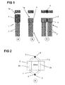
- a stator of an electric machine In the course of manufacturing a stator of an electric machine using shaped wires, in a first step, these shaped wires 1 for insertion into the grooves 2a of the stator 2 and for forming the winding of the stator 2 are produced.
- the Fig. 1 shows a schematic representation of three essential steps in the manufacturing process of a winding for a stator of an electric machine. At the far left and designated A, a stranded wire 1 is shown, the end 1 a is provided with a sleeve 4. In order to reliably prevent the formation of domains in cross section, which run mostly in the interior of the stranded wire 1, usually the individual wires 7 are twisted multiple times.
- the stranded wire 1 is penetrated during operation by various magnetic fields (stray fields, rotor fields, ). Since it is electrically short-circuited at both ends 1a by the electrical connection between the individual wires 7 of the stranded wires 1, which is accomplished at least in part via the sleeve 4, form between the individual wires 7 one and the same stranded wire 1 one or more conductor loops. In these conductor loops, a voltage is induced by the existing field.
- the parasitic currents in the conductor loop, which follow from the induced voltages should be as low as possible, which can be achieved via a suitable type of twisting and stranding.
- the individual wires 7 of the shaped strands which consist for example of copper, aluminum or similar electrically conductive materials, each surrounded by an insulating lacquer layer.
- the twisting and the deformation into the desired shape causes the individual wires 7 are pressed together with their paint layers.
- the lacquer layers of adjacent individual wires 7 stick together, for example by adding an additional material (for example a resin), or ensure adhesion, which gives the shaped strands 1 as a whole stability.
- the twisted individual wires 7 can be soaked with an adhesive, such as resin.
- the use of baked enamel wires may make sense, which type of wires baked together by heat. Also by this measure improved stability can be achieved.
- these connecting components can be applied to the rollers from the outside.
- these connecting components can also already be present on the wire, which represents the individual wires 7 of the stranded wire 1, as is the case with back-lacquer-coated wires.
- the materials connecting the individual wires could also be present within the strand. Similar to fiber composites, for example, one or more filaments of a polymer could be drilled in, which treats on later heating and cakes the strand packet.
- the mechanical connection takes place together with the electrical contact on at least one of the ends 1a of the shaped strands 1, additionally such a mechanical connection can be provided over the covering or insulation of the individual wires 7.
- the shaped strands 1 are also brought to the desired length, preferably cut to size.
- This also has the advantage that the compacted during the compaction of the individual wires 7 of the stranded wire 1 or during compression of the sleeve 4 in the direction of the outer end 1a of the stranded wire 1 ausquetsche adhesive or similar contaminants are cut away.
- the shortened sleeve 4 of in Fig.1 in the middle - letter B - illustrated stranded wire 1 is already clean or easy to clean, so that a secure connection with another stranded wire 1 can be produced.
- An example of an advantageous joining method is a soldering process.
- two adjacent surfaces of two sleeves 4 different shaped strands 1 are connected by a braze, which may already be on a sleeve side before.
- the braze can also be done after Assembling the ends 1a of the form strands 1 are added.
- the heating of the solder can be accomplished by a variety of processes: heating by a flame, inductive heating, etc.
- a connection of the sleeves 4 by welding, in particular by resistance welding, is possible. Due to the good lateral accessibility in the stator 2, the two sleeves 4 can be pressed together well, positioned and then connected.
- the stranded wire 1 is contacted after cutting at its two ends 1 a.
- the contacting is preferably carried out over a certain longitudinal section at the respective end 1a of the stranded wire 1 and preferably by a welding operation, preferably by resistance welding.
- a welding operation preferably by resistance welding.
- the connection process preferably comprises all the individual wires at the respective end 1a of the shaped strands 1, in order to ensure optimum stability and electrical connection.
- the individual wires of the stranded wire 1 can be contacted before cutting to preferably both ends 1a, ie both electrically conductive contacted as well as mechanically connected, are.
- the shaped strands 1 in one cut to length in the following process step.
- the clearly defined geometry of the ends 1a of the stranded wire 1 significantly simplifies the automation in contrast to conventional shaped strands, the geometry of which can be changed by twisting or displacement of the individual wires.
- the contacting of the inner and outer stranded wire 1 within each of the stator slots 2a and the irregular interconnections is also simplified, since the individual wires are already electrically connected by the respectively selected connection method.
- At least one of the contacted - and thus also mechanically connected - ends 1a of the shaped strands 1 are also compacted, i. it is the cross-section of this end 1 a or at least reduced to a circumferential position of the diameter or at least the width at a point of this end 1 a.
- both ends 1a of the stranded wire 1 can be achieved that the outer geometry of the ends 1 a as well as those of the central longitudinal portion 1 b of the shaped strands 1 is preferably smaller at each point of the circumference than the groove geometry.
- the novel shaped strands 1 with their contacted and compacted ends 1a can be inserted automatically into the stator slots 2a.
- a radial insertion into the stator 2 is not possible with parallel grooves 2a with groove base with superimposed (and not adjacent) form rods because of the groove foot.
- this is also not possible because in internal running machines, the trapezium tapers inwards.
- the shaping strands 1 can also be inserted radially.
- the enveloping cross section of the shaped strand 1 in at least one of the longitudinal sections of interconnected individual wires is smaller than the cross section in the subsequent longitudinal section.
- the cross-sectional shape of the stranded wire 1 corresponds to the trapezoidal shape of the stator 2a, at least in the central longitudinal section between the electric and mechanically connected and also compacted to a smaller cross-section ends 1 a.
- the smaller cross section is provided at least at that end of the stranded wire 1 on the axially inserted into the stator 2 end of the stranded wire 1.
- the form wires 1 are not damaged during insertion and even adjacent Form strands 1 or the stator are not damaged. Both damage to the insulation of the individual wires and / or the slot insulation can be prevented, regardless of whether the slot insulation is already in the groove 2a or is on the stranded wire 1 at least before insertion. Likewise, damage to the stator 2, such as scratching of the sheets, can be prevented, whereby the efficiency of the machine worsening shorts can be prevented.
- Fig. 2 schematically shows a stator with two shaped strands 1, the connection via as in Fig. 1 on the far right (letter C) are mechanically and electrically connected.
- the shaped strands 1 are bent towards each other and then over the sleeves 4 connected. The fact that a flat connection between the two sleeves 4 is made, the angle between the two sleeves is arbitrary. Thus, a reverse bend behind the longitudinal section of the sleeve 4 of the stranded lines 1 can be avoided, resulting in the advantage of a shorter winding head, as in Fig. 2 can be seen.
- At least one end 1a can be tapered in a linear, conical, pyramidal or irregular taper, which naturally simplifies insertion into the stator 2. Likewise, this can offer 2 advantages for the downstream connection process in the winding head of the stator.
- the electrically conductive and also mechanically fixing connection of two pointed ends 1a of two different shaped strands 1 can be particularly advantageous at a geometrically defined end (eg pointed embodiment of the ends 1a, or also defined flat geometry or geometry in which a notch between the shaping strands 1) can be produced by a process in which current flows from an electrode E into the tapered ends 1a of the shaping wires 1 and thus by the fusion of the shaped strands 1 with or without additives an electrical and mechanical connection 3 small dimensions, substantially point or line, produces.
- the connection of two pointed ends 1 a two shaped strands 1 by a TIG welding process, possibly without additive are prepared.
- the shaped strands 1 are bent towards each other with their ends 4 a provided with sleeves 1 a and provided at the points of contact in the same way with an electrical and mechanical connection 3 small dimensions, substantially approximately point or line.
- connection of two converging shaped strands 1 with or without sleeves 4 to the stator 2 projecting ends 1 a by resistance welding or a similar method also linear over a larger longitudinal section of the ends 1 a or even be performed flat.
- the defined geometry of the ends 1a offers advantages over shaped strands of unconnected individual wires.
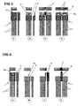
- the Fig. 3 shows a variant in which a tab 8 is inserted longitudinally in the sleeve 4.
- a first step shown on the left with the letter A, sleeve 4 and tab 8 are the same length.
- the individual wires 7 of the raw shaped strand 1 are also inserted into the sleeve 4.
- Sleeve 4, tab 8 and the individual wires 7 are pre-compacted together. It is, as already in connection with Fig. 1 explained, the single wire insulation heats and melts. By pressing during precompacting, the insulation exits from the front of the stranded wire 1.
- the tab 8 When subsequently shortening the stranded wire 1 and the sleeve 4, the tab 8 is excluded so that it finally protrudes beyond the end 1a of the stranded wire 1 and over the sleeve 4.
- the shortening can be done for example by milling or by a sheet metal cutting process.
- a tab 8 made of pure copper is used. After removing any remaining pollution, this tab 8 can be used for the subsequent connection process. In this case, about two tabs 8 different shaped strands 1 are welded together directly, as in Fig. 3 , Letter C, is shown.
- the tabs 8 can be in the connection region 3 with their flat surfaces or with their side edges together.
- a connection piece 8a of an electrically conductive material for example, copper bar
- the connection of the shaped strands 1 are accomplished.
- Such a compound is in Fig. 3 on the far right, at the letter C '. Due to the good accessibility from above in the stator 2, all these welding processes can be carried out from above.
- the tab 8 can possibly be welded to the already shortened sleeve 4.
- the two flags thus formed can then be welded together from above, as in Fig. 4 again on the far right, at the letter D, represented
- a sleeve 4 which is designed thicker on one side.
- a step is cut into the sleeve 4, so that the thicker side protrudes as a tab 8.
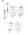
- FIG. 5 An advantageous embodiment for producing the winding of a stator using shaped wires 1 with tabs 8 on the sleeves 4 is in the sequence of steps of Fig. 5 shown.
- This method can be applied to all shaped strands 1 with tabs 8.
- Formed wires 1 are preferably used, in which the tabs 8 are provided at both ends, but asymmetrical.
- the tab 8 at the end 1a of the stranded wire 1, which end is inserted through the stator 2 is elongated and the sleeve designed to be outstanding in the axial direction, so that it does not exceed the available cross-section of the stator 2a.
- the tab 8 at the other end 1a of the stranded wire 1, which is not plugged through the stator 2 is in principle freely designable in its geometry.
- the shaped strands 1 can also be inserted from different positions in the groove from different sides (illustrations of the letters A and B of Fig. 5 ).
- the tabs are 8 after bending (letter C) directly above each other (as in the figure at the letter D of Fig. 5 ). This can save a second bending process.
- connection methods already explained above be applied to the adjacent tabs 8 mechanically and electrically to the state as in letter E of Fig. 5 shown to connect. Again, the advantage of a shorter winding head can be achieved again.
Landscapes
- Engineering & Computer Science (AREA)
- Power Engineering (AREA)
- Manufacturing & Machinery (AREA)
- Manufacture Of Motors, Generators (AREA)
- Windings For Motors And Generators (AREA)
Abstract
Eine Wicklung für einen Stator (2) einer elektrischen Maschine besteht aus miteinander mechanisch als auch elektrisch leitend verbundenen Formlitzen (1). Zumindest einige der Einzeldrähte (7) jeder Formlitze (1) sind an zumindest einem Ende (1a) durch eine Hülse (4) aus elektrisch leitendem Material mechanisch und elektrisch leitend miteinander und mit der Hülse (4) verbunden. Die Hülsen (4) zweier in der Wicklung in Richtung des Stromflusses aufeinanderfolgender Formlitzen (1) sind mechanisch und elektrisch leitend verbunden.

Description
Die Erfindung betrifft eine Wicklung für einen Stator einer elektrischen Maschine, insbesondere den Stator einer Drehfeldmaschine wie einem Motor oder Generator, insbesondere für ein Elektro- oder Hybridfahrzeug, nach dem Oberbegriff des Anspruchs 1, eine elektrische Maschine mit einem Stator, insbesondere Drehfeldmaschine, wie Motor oder Generator, insbesondere für ein Elektro- oder Hybridfahrzeug, deren Wicklung unter Verwendung von Formlitzen hergestellt ist, nach dem Oberbegriff des Anspruchs 10, sowie ein Verfahren zur Herstellung der Wicklung für einen Stator einer elektrischen Maschine, insbesondere den Stator einer Drehfeldmaschine wie einem Motor oder Generator, insbesondere für ein Elektro- oder Hybridfahrzeug,nach dem Oberbegriff des Anspruchs 11.The invention relates to a winding for a stator of an electrical machine, in particular the stator of a rotating field machine such as a motor or generator, in particular for an electric or hybrid vehicle, according to the preamble of
Als Wicklung ist im Stand der Technik z.B. eine verteilte Wicklung bekannt. Damit diese Antriebsmaschinen einen hohen Systemwirkungsgrad und eine sehr geringe Drehmomentwelligkeit erreichen, hat sich als Bewicklung des Stators für Antriebsmaschinen von Straßenfahrzeugen im Leistungsbereich oberhalb 70kW die sogenannte verteilte Wicklung etabliert. Auch wenn die verteilte Wicklung bei Industriemotoren ähnlicher Baugröße dominiert, haftet ihr der Ruf der schlechten Herstellbarkeit aufgrund geringer Möglichkeit der Automatisierung an. So erweisen sich vor allem die Prozessschritte der Verschaltung der einzelnen Spulen als nur bedingt großserientauglich.As a winding, in the prior art e.g. a distributed winding known. In order for these prime movers to achieve a high system efficiency and a very low torque ripple, the so-called distributed winding has established itself as a winding of the stator for drive machines of road vehicles in the power range above 70kW. Although the distributed winding is dominated by industrial motors of similar size, the reputation of poor manufacturability due to the low possibility of automation attached to it. In particular, the process steps of the interconnection of the individual coils prove to be of limited suitability for mass production.
Bekannt ist auch die Technik der sogenannten Formstäbe (im Grossmaschinenbau Roebelstäbe genannt), welche in Nuten geschoben werden und stirnseitig entsprechend verbunden werden. Dadurch, dass die Stäbe aber gerade und nicht verdrillt sind, ist zwar die Automatisierbarkeit des Einschubprozesses, des Biegeprozesses und des Verschaltens zur Fertigstellung der Wicklung relativ einfach, jedoch leidet der Wirkungsgrad der elektrischen Maschine unter den Stromverdrängungseffekten des Kupfervollmaterials.Also known is the technique of the so-called form bars (called Roebel rods in large machine construction), which are pushed into grooves and are connected correspondingly at the ends. However, by virtue of the rods being straight and not twisted, the automation of the insertion process, the bending process, and the interconnection to complete the winding is relatively simple, but the efficiency of the electrical machine suffers from the current displacement effects of the bulk copper material.
Unterschieden zu den Roebelstäben bzw. der Hair-Pin Wicklung ist die Formlitzen-Technik, bei welcher einzelne relativ dünne verdrillte Kupferleiter, denkbar wäre auch Aluminium oder ein anderes elektrisch leitendes Material, eingesetzt werden. Verfahren zur Herstellung eines Stators für eine elektrische Maschine mit Formlitzen-Technik umfassen das Einsetzen einer Mehrzahl von Formlitzen in die durch Statorzähne getrennte Nuten des Stators. Diese Formlitzen werden dann zur Bildung der Wicklung des Stators elektrisch leitend miteinander verbunden. Wenn sich die Formlitzen im Stator befinden, werden Sie oftmals zueinander verbogen, um eine Wellenwicklung zu realisieren. Während dieses Biegeprozesses besteht ebenfalls das Problem des Aufdrillens der Formlitze.Differences to the Roebel bars or the Hair-Pin winding is the Formlitzen technique, in which individual relatively thin twisted copper conductors, conceivable would be aluminum or another electrically conductive material used. Method for producing a stator for a wire-wound electric machine include inserting a plurality of shaped strands into the stator-separated slots of the stator. These shaped strands are then electrically connected to one another to form the winding of the stator. When the form wires are in the stator, they are often bent to each other to realize a wave winding. During this bending process, there is also the problem of twisting the stranded wire.
Grundsätzlich ist das Problem beim Verbinden von Formlitzen durch einen Schweiss- oder Lötprozess die Verschmutzung im Verbindungsbereich. Da durch das Vorkompaktieren im Zuge der Herstellung der Formlitze selbst die Isolation von deren Einzeldrähten weggebrannt wird, befinden sich im Verbindungsbereich auch nach ordentlichem Reinigen immer noch Lackreste, welche die Verbindungsstelle verschmutzen und somit im Verbindungsprozess stören. Durch diese Verschmutzung ist Prozesssicherheit nicht gegeben.Basically, the problem when joining shaped wires by a welding or soldering process, the pollution in the connection area. Since the pre-compacting in the course of production of the stranded wire itself, the insulation is burned away from their individual wires, are still in the connection area after proper cleaning paint residues that pollute the junction and thus interfere in the connection process. Due to this contamination process reliability is not given.
Die Aufgabe der vorliegenden Erfindung ist eine Wicklung auf der Basis von Formlitzen, bei deren Einsatz in elektrischen Maschinen nicht nur die Effizienz und die thermische Dauerleistungsfähigkeit verbessert ist, sondern insbesondere eine vereinfachte automatisierte Herstellbarkeit der Stator-Wicklung ermöglicht ist. Eine weitere Aufgabe der Erfindung ist ein vereinfachtes und einfach automatisierbares Herstellverfahren für eine derartige Wicklung.The object of the present invention is a winding on the basis of shaped strands, whose use in electrical machines not only improves the efficiency and the continuous thermal performance, but in particular enables simplified automated manufacturability of the stator winding. Another object of the invention is a simplified and easily automatable manufacturing process for such a winding.
Die Aufgabe wird durch die Merkmale der unabhängigen Ansprüche 1, 10 und 11 gelöst. Vorteilhafte Weiterbildungen sind in den Figuren und in den abhängigen Patentansprüchen dargelegt.The object is solved by the features of
Die Erfindung geht dabei aus von einer Wicklung für einen Stator einer elektrischen Maschine. Dies kann insbesondere eine Wicklung für den Stator einer Drehfeldmaschine wie einem Motor oder Generator sein, wie er in Elektro- oder Hybridfahrzeugen zum Einsatz kommt. Diese Wicklung besteht typischerweise aus miteinander mechanisch als auch elektrisch leitend verbundenen Formlitzen, welche ihrerseits aus einer Mehrzahl von einzeln isolierten und vorteilhaft parallel verlaufenden und vorzugsweise verdrillten Einzeldrähten und gegebenenfalls einer allen Einzeldrähten gemeinsamen äusseren Umhüllung aufgebaut sind.The invention is based on a winding for a stator of an electric machine. This may in particular be a winding for the stator of a rotating field machine such as a motor or generator, as used in electric or hybrid vehicles. This winding typically consists of mechanically or electrically connected form wires, which in turn are composed of a plurality of individually insulated and advantageously parallel and preferably twisted individual wires and, if appropriate, an outer covering common to all individual wires.
Zur Lösung der oben genannten Aufgabe ist nun diese Wicklung erfindungsgemäss dadurch gekennzeichnet, dass zumindest einige der Einzeldrähte jeder Formlitze an zumindest einem Ende der Formlitze, vorzugsweise an beiden Enden, durch eine diese Einzeldrähte, vorzugsweise alle Einzeldrähte, umschliessende Hülse aus elektrisch leitendem Material mechanisch und elektrisch leitend miteinander und mit der Hülse verbunden sind. Als weiteres wesentliches Merkmal der erfindungsgemässen Wicklung sind die Hülsen zweier in der Wicklung in Richtung des Stromflusses aufeinanderfolgender Formlitzen mechanisch und elektrisch leitend verbunden. Damit ist eine wesentlich sicherere, rasch herstellbare und durch einen einfach automatisierbaren Prozess machbare Wicklung gegeben. Hier als auch in weiterer Folge wird der Begriff "aufeinanderfolgend" in Anwendung auf die Formlitzen od. dgl. so verwendet, dass damit in Richtung des Stromflusses hintereinanderliegende Elemente gemeint sind, was nicht unbedingt mit unmittelbarer örtlicher Nähe übereinstimmen muss.To achieve the above object, this winding is now according to the invention characterized in that at least some of the individual wires of each form strand at least one end of the stranded wire, preferably at both ends, by a these individual wires, preferably all individual wires, enclosing sleeve of electrically conductive material are mechanically and electrically conductively connected to each other and to the sleeve. As a further essential feature of the winding according to the invention, the sleeves of two winding strands in the direction of the current flow of successive shaped strands are mechanically and electrically conductively connected. This provides a much safer, rapidly producible and feasible by a simple automatable process winding. Here as well as subsequently, the term "successive" in application to the form strands od. Like. Used so that in the direction of the current flow consecutive elements are meant, which does not necessarily coincide with immediate local proximity.
Vorzugsweise werden dabei insbesondere die nach Abschneiden der äusseren Enden der Formlitze einschliesslich der Hülse verbleibenden Hülsenabschnitte miteinander verbunden. Damit werden diejenigen Abschnitte der Formlitzen entfernt, in welchen die meiste Verschmutzung vorliegt, da sich insbesondere beim Kompaktieren des Endes der Formlitze der ausgequetschte Lack bzw. das ausgequetschte Isoliermaterial im weniger kompaktierten äusseren Ende der Formlitze ansammelt.In this case, in particular, the sleeve sections remaining after cutting off the outer ends of the shaped strand including the sleeve are preferably connected to one another. Thus, those portions of the shaped strands are removed, in which there is the most pollution, since accumulates in particular when compacting the end of the stranded wire of the squeezed paint or the squeezed insulating material in the less compacted outer end of the stranded wire.
Bevorzugt sind die Hülsen durch ein Schweissverfahren verbunden, vorzugsweise durch Widerstandsschweissen.Preferably, the sleeves are connected by a welding process, preferably by resistance welding.
Alternativ dazu können die Hülsen auch durch ein Lötverfahren verbunden sein, wobei die Verbindung vorzugsweise durch ein Hartlot hergestellt ist. Beide Verfahren sind sehr erprobt, prozesssicher und erlauben somit die einfache Herstellung einer stabilen und elektrisch leitenden Verbindung.Alternatively, the sleeves may also be connected by a soldering process, the connection preferably being made by a brazing solder. Both methods are very tried and tested, process-reliable and thus allow easy production of a stable and electrically conductive connection.
Um den Stromfluss möglichst wenig zu behindern und eine grossen Leitungsquerschnitt auch im Verbindungsbereich der Formlitzen zu gewährleisten, liegen die Hülsen an der Verbindungsstelle bevorzugt flächig aneinander.In order to hinder the flow of current as little as possible and to ensure a large cross-section in the connecting region of the shaped strands, the sleeves are preferably flat against each other at the junction.
Eine weitere Ausführungsform der Erfindung ist dadurch gekennzeichnet, dass die Hülsen an zumindest einem Ende der Formlitzen mit einer Lasche versehen sind und die Verbindung zweier Formlitzen über die zumindest eine Lasche hergestellt ist. Durch diese Vergrösserung der Hülse ist die Handhabung erleichtert und eine bessere und sicherere Verbindung zweier Formlitzen-Enden ermöglicht.A further embodiment of the invention is characterized in that the sleeves are provided on at least one end of the shaped strands with a tab and the connection of two shaped strands made on the at least one tab is. By this enlargement of the sleeve handling is facilitated and allows a better and safer connection of two Formlitzen ends.
Eine derartige Lasche kann sich beispielsweise axial über das Ende der Formlitzen hinaus erstrecken oder auch radial von der Formlitze weg ragen. Beide Varianten gestatten es, die Formlitze besser zu greifen und zu bewegen und vergrössern auch den Bereich, über welchen eine mechanische als auch elektrisch leitende Verbindung mit einer anschliessenden Formlitze hergestellt werden kann.Such a tab may, for example, extend axially beyond the end of the shaped strands or also project radially away from the shaped strand. Both variants make it possible to better grip and move the stranded wire and also enlarge the area over which a mechanical and electrically conductive connection can be made with a subsequent stranded wire.
Bevorzugt sind ein einem Ende der Formlitze eine sich axial über das Ende der Formlitzen hinaus erstreckende Lasche und am entgegengesetzten Ende der Formlitze eine radial von der Formlitze weg ragende Lasche angeordnet.Preferably, a tab extending axially beyond the end of the shaped strands is disposed at one end of the shaped strand, and a tab projecting radially away from the formed strand is disposed at the opposite end of the preformed strand.
Weiters ist bevorzugt, dass aufeinanderfolgende Formlitzen jeweils entgegengesetzt ausgerichtet sind und die Laschen unterschiedlicher Ausrichtung miteinander verbunden sind, was ebenfalls die Handhabung der Formlitzen als auch deren Verbindung untereinander erleichtert.Furthermore, it is preferred that successive shaped strands are each oriented in opposite directions and the tabs of different orientation are connected to each other, which also facilitates the handling of the shaped strands and their connection with each other.
Gemäss einer weiteren Ausführungsform der Erfindung ist vorgesehen, dass das äusserste Ende jedes Längsabschnittes am Ende der Formlitze einschliesslich der Hülse eine definierte Geometrie aufweist, wobei das äusserste Ende jedes Längsabschnittes am Ende der Formlitze vorzugsweise zugespitzt ausgeführt ist und zumindest linienförmig oder dachartig zulaufend endet oder ein flaches Ende mit einer Schweissnaht entlang der Verbindungslinie vorgesehen ist, oder eine Kerbe aufweist.According to a further embodiment of the invention, it is provided that the outermost end of each longitudinal section at the end of the shaped strand including the sleeve has a defined geometry, wherein the outermost end of each longitudinal section is preferably pointed at the end of the shaped strand and ends or at least tapered or roof-like flat end is provided with a weld along the connecting line, or has a notch.
Bevorzugt sind die Hülsen und der Bereich der flächigen Verbindung mit den Hülsen der jeweils vorhergehenden bzw. nachfolgenden Formlitzen in einem Längsabschnitt der Formlitzen angeordnet, der in Bezug auf die Längsrichtung der Statornut schräg verläuft, und ende die Hülse sowie die Formlitze am Ende dieses schrägen Längsabschnittes. Aufgrund der flächigen Verbindung zwischen den Hülsen der verbundenen Formlitzen ist der Winkel zwischen den zwei Hülsen und damit den Enden der Formlitzen frei wählbar, so dass Konzepte ohne eine Gegenbiegung - d.h. ohne Endabschnitt der Formlitzen, der gegensinnig zur Biegung auf die zu verbindende andere Formlitze hin verläuft - möglich werden. Dies hat den großen Vorteil eines kürzeren Wickelkopfes, da somit die sonst notwendigen, parallel zu den Statornuten und der Statorachse verlaufenden Endbereiche der Formlitzen vermieden werden können.Preferably, the sleeves and the region of the surface connection with the sleeves of the respective preceding or succeeding shaped strands are arranged in a longitudinal section of the shaped strands, which runs obliquely with respect to the longitudinal direction of the stator slot, and end the sleeve and the stranded line at the end of this oblique longitudinal section , Due to the areal connection between the sleeves of the connected shaped strands, the angle between the two sleeves and thus the ends of the shaped strands is freely selectable, so that concepts without a counterbending - ie without end portion of the form strands, in the opposite direction to the bend to be connected to the other strand strand runs - be possible. This has the great advantage of a shorter winding head, since thus the otherwise necessary, parallel to the Statornuten and the stator axis extending end portions of the form wires can be avoided.
Die Lösung der eingangs gestellten Aufgabe gelingt auch durch eine elektrische Maschine mit einem Stator, dessen Wicklung unter Verwendung von Formlitzen hergestellt ist, und welche dadurch gekennzeichnet ist, dass die Wicklung gemäss einem der vorhergehenden Absätze aufgebaut ist. Diese elektrische Maschine ist insbesondere eine Drehfeldmaschine, wie Motor oder Generator, insbesondere für ein Elektro- oder Hybridfahrzeug.The solution of the object is achieved by an electric machine with a stator, the winding is made using stranded wire, and which is characterized in that the winding is constructed according to one of the preceding paragraphs. This electric machine is in particular an induction machine, such as a motor or generator, in particular for an electric or hybrid vehicle.
Weiters wird diese eingangs dargelegte Aufgabe gelöst durch ein Verfahren zur Herstellung der Wicklung für einen Stator einer elektrischen Maschine gelöst, das das Einbringen vorgefertigter Formlitzen in Nuten des Stators und die anschliessende Herstellung einer zumindest elektrisch leitenden Verbindung zwischen den aus den Statornuten herausragenden Enden der Formlitzen umfasst. Wiederum betrifft dies insbesondere den Stator einer Drehfeldmaschine wie einem Motor oder Generator, dessen Einsatzgebiet besonders vorteilhaft Elektro- oder Hybridfahrzeuge sind.Furthermore, this object is achieved at the outset achieved by a method for producing the winding for a stator of an electric machine, comprising the introduction of prefabricated stranded in grooves of the stator and the subsequent production of an at least electrically conductive connection between the projecting from the stator ends of the form wires , Again, this relates in particular to the stator of a rotary field machine, such as a motor or generator whose field of use is particularly advantageous electric or hybrid vehicles.
Erfindungsgemäss werden zumindest einige der Einzeldrähte jeder Formlitze an zumindest einem Ende der Formlitze, vorzugsweise an beiden Enden, durch eine diese Einzeldrähte umschliessende Hülse aus elektrisch leitendem Material mechanisch und elektrisch leitend miteinander und mit der Hülse verbunden. Vorzugsweise werden dabei alle vorhandenen Einzeldrähte verbunden und auch von der Hülse ummantelt.According to the invention, at least some of the individual wires of each shaped strand are mechanically and electrically conductively connected to one another and to the sleeve at at least one end of the shaped strand, preferably at both ends, by a sleeve of electrically conductive material enclosing these individual wires. Preferably, all existing individual wires are connected and also sheathed by the sleeve.
Um die sich typischerweise an den äussersten Enden ansammelnden Verschmutzungen, insbesondere beim Kompaktieren ausgequetschtes Isoliermaterial der Einzeldrähte, einfach zu entfernen, wird vorzugsweise das äussere Ende der Formlitze einschliesslich der Hülse abgeschnitten. Anschliessend werden rasch und prozesssicher die Hülsen zweier in der Wicklung in Richtung des Stromflusses aufeinanderfolgender Formlitzen mechanisch und elektrisch leitend verbunden.In order to easily remove the soiling, which is typically accumulated at the outermost ends, especially the insulation material of the individual wires squeezed out during compacting, preferably the outer end of the shaped strand including the sleeve is cut off. Subsequently, the sleeves of two in the winding in the direction of the flow of current successive stranded wires are mechanically and electrically conductively connected quickly and reliably.
Bevorzugt wird zur leichteren Handhabung der Formlitzen die Anbringung der Hülse und die mechanisch und elektrisch leitende Verbindung mit den Einzeldrähten bereits vor dem Einbringen der Formlitze in die Statornut durchgeführt.Preferably, the attachment of the sleeve and the mechanically and electrically conductive connection with the individual wires is carried out prior to the introduction of the stranded wire into the stator for ease of handling of the shaped strands.
Sehr prozesssicher und auch einfach zu automatisieren ist eine Ausführungsform des Verfahrens, bei welchem die Hülsen durch ein Schweissverfahren mechanisch und elektrisch leitend mit den Einzeldrähten verbunden werden, vorzugsweise durch Widerstandsschweissen.Very reliable and also easy to automate is an embodiment of the method in which the sleeves are mechanically and electrically conductively connected to the individual wires by a welding process, preferably by resistance welding.
Gleiches gilt auch für eine Variante, bei welcher die Hülsen durch ein Lötverfahren mechanisch und elektrisch leitend mit den Einzeldrähten verbunden werden, vorzugsweise unter Verwendung eines Hartlotes.The same applies to a variant in which the sleeves are connected by a soldering mechanically and electrically conductive with the individual wires, preferably using a brazing alloy.
Um einen optimalen Stromfluss zwischen den verbundenen Formlitzen zu gewährleisten, werden die Hülsen oder allfällige abstehende Fortsätze, Fahnen, Laschen oder dergleichen an der Verbindungsstelle flächig aneinander in Anlage gebracht.In order to ensure an optimal flow of current between the connected shaped strands, the sleeves or any projecting extensions, flags, tabs or the like are brought into abutment against one another at the connection point.
Bei allen erfindungsgemässen Lösungen und Ausführungsformen ist bevorzugt immer eine im Wesentlichen ebene Fläche als Verbindungsstelle gegeben, die sauber und frei von Verschmutzungen ist bzw. einfach gereinigt werden kann. Zudem ist es bei allen Ausführungsformen vorteilhaft, wenn die Hülse (inklusive allfälliger daran vorgesehener Verbindungselemente wie Laschen etc.) bei mindestens einer Formlitze kleiner ist als die dafür vorgesehene Nutgeometrie.In all the solutions and embodiments according to the invention, it is preferred to always provide an essentially flat surface as a connection point, which is clean and free from contamination or can simply be cleaned. In addition, it is advantageous in all embodiments, if the sleeve (including any provided thereon fasteners such as tabs, etc.) is smaller in at least one stranded wire than the designated groove geometry.
Weitere Vorteile, Merkmale und Einzelheiten der Erfindung ergeben sich aus der nachfolgenden Beschreibung, in der unter Bezugnahme auf die Zeichnungen Ausführungsbeispiele der Erfindung beschrieben sind. Dabei können die in den Ansprüchen und in der Beschreibung erwähnten Merkmale jeweils einzeln für sich oder in beliebiger Kombination erfindungswesentlich sein.Further advantages, features and details of the invention will become apparent from the following description in which embodiments of the invention are described with reference to the drawings. The features mentioned in the claims and in the description may each be essential to the invention individually or in any desired combination.
Die Bezugszeichenliste ist Bestandteil der Offenbarung. Die Figuren werden zusammenhängend und übergreifend beschrieben. Gleiche Bezugszeichen bedeuten gleiche Bauteile, Bezugszeichen mit unterschiedlichen Indices geben funktionsgleiche oder ähnliche Bauteile an.The list of reference numerals is part of the disclosure. The figures are described coherently and comprehensively. The same reference symbols denote the same components, reference symbols with different indices indicate functionally identical or similar components.
Es zeigen dabei:
- Fig. 1
- eine schematische Darstellung der Verbindung zweier Formlitzen mit Hülsen an deren Ende,
- Fig. 2
- eine schematische Darstellung eine Stators mit kurzem Wickelkopf,
- Fig. 3
- eine schematische Darstellung der Verbindungsmöglichkeit von Formlitzen mit Hülsen mit Laschen,
- Fig. 4
- eine andere Ausführungsform der Verbindungsmöglichkeit von Formlitzen mit Hülsen mit Laschen in schematischer Darstellung, und
- Fig. 5
- einige Schritte im Herstellungsverfahren einer Statorwicklung unter Verwendung von Formlitzen mit Hülsen mit Laschen.
- Fig. 1
- a schematic representation of the connection of two shaped strands with sleeves at the end,
- Fig. 2
- a schematic representation of a stator with a short winding head,
- Fig. 3
- a schematic representation of the possibility of connecting shaped wires with sleeves with tabs,
- Fig. 4
- another embodiment of the possibility of connecting form wires with sleeves with tabs in a schematic representation, and
- Fig. 5
- some steps in the manufacturing process of a stator winding using shaped wires with sleeves with tabs.
Im Zuge der Herstellung eines Stators einer elektrischen Maschine unter Verwendung von Formlitzen werden in einem ersten Schritt diese Formlitzen 1 zum Einsetzen in die Nuten 2a des Stators 2 und zur Bildung der Wicklung des Stators 2 hergestellt. Die
Die Formlitze 1 wird im Betrieb von diversen Magnetfeldern durchdrungen (Streufelder, Rotorfelder, ...). Da sie an beiden Enden 1a durch die elektrische Verbindung zwischen den Einzeldrähten 7 der Formlitzen 1 elektrisch kurzgeschlossen ist, was zumindest zum Teil über die Hülse 4 bewerkstelligt ist, bilden sich zwischen den Einzeldrähten 7 ein und derselben Formlitze 1 eine oder mehrere Leiterschleifen. In diesen Leiterschleifen wird durch das vorhandene Feld eine Spannung induziert. Die parasitären Ströme in den Leiterschleife, die aus den induzierten Spannungen folgen, sollen möglichst gering ausfallen, was über eine geeignet Art der Verdrillung und Verseilung erreicht werden kann.The stranded
Üblicherweise sind die Einzeldrähte 7 der Formlitzen 1, die z.B. aus Kupfer, Aluminium oder ähnlichen elektrisch leitenden Materialien bestehen, jeweils von einer isolierenden Lackschicht umgeben. Das Verseilen bzw. Verdrillen und das Nachformen in die gewünschte Form bewirkt, dass die Einzeldrähte 7 mit ihren Lackschichten aneinandergedrückt werden. Die Lackschichten benachbarter Einzeldrähte 7 verkleben miteinander, beispielsweise durch Hinzugeben eines zusätzlichen Werkstoffs (z.B. eines Harzes), bzw. sorgen für eine Haftung, was den Formlitzen 1 als Ganzes Stabilität verleiht. Zusätzlich bzw. bei anderen Metallen, z.B. Aluminium, die von einer isolierenden Oxidschicht bedeckt sind, können die verdrillten Einzeldrähte 7 mit einem Kleber, z.B. Harz, getränkt werden. Zudem kann der Einsatz von Backlackdrähten sinnvoll sein, welche Art von Drähten durch Hitzeeinwirkung miteinander verbacken. Auch durch diese Maßnahme kann verbesserte Stabilität erreicht werden.Usually, the
Für die mechanische Festigkeit innerhalb der Formlitze 1 können diese verbindenden Komponenten nach den Walzen von aussen aufgebracht werden. Dazu kommen als Imprägnierung beispielsweise Epoxy-Harze oder Silikon-Harze oder Vergussmassen auf Epoxy-Basis oder auf Polyurethan-Basis in Frage. Die Komponente können aber auch schon auf dem Draht vorhanden sein, der die Einzeldrähte 7 der Formlitze 1 darstellt, wie dies bei backlackbeschichteten Drähten der Fall ist. Schliesslich könnten die die Einzeldrähte verbindenden Materialien auch innerhalb der Litze vorhanden sein. Ähnlich wie bei Faserverbundwerkstoffen könnten beispielsweise ein oder mehrere Fäden eines Polymers mit eingedrillt werden, das bei späterem Erwärmen verfliesst und das Litzenpaket zusammenbackt. Auch bei anderen Ausführungsformen der Formlitzen 1, bei der die mechanische Verbindung zusammen mit der elektrischen Kontaktierung an zumindest einem der Enden 1a der Formlitzen 1 erfolgt, kann zusätzlich eine derartige mechanische Verbindung über die Umhüllung bzw. Isolierung der Einzeldrähte 7 vorgesehen sein.For the mechanical strength within the stranded
Vor dem Einsetzen in den Stator 2 werden die Formlitzen 1 auch auf die gewünschte Länge gebracht, vorzugsweise zugeschnitten. Das hat auch den Vorteil, dass sich der beim Kompaktieren der Einzeldrähte 7 der Formlitze 1 bzw. beim Zusammenpressen der Hülse 4 in Richtung äusseres Ende 1a der Formlitze 1 ausgequetsche Kleber oder ähnliche Verschmutzungen weggeschnitten werden. Die gekürzte Hülse 4 der in
Ein Beispiel für ein vorteilhaftes Verbindungsverfahren ist ein Lötprozess. Bei dieser Variante werden durch ein Hartlot, welches sich eventuell schon vorher auf einer Hülsenseite befindet, zwei aneinanderliegende Flächen zweier Hülsen 4 verschiedener Formlitzen 1 miteinander verbunden. Somit ist im Verbindungsbereich 3 eine sowohl mechanische als auch elektrisch leitende Verbindung gegeben, wie in
In einer Ausführungsform des Verfahrens wird die Formlitze 1 nach dem Ablängen an ihren beiden Enden 1 a kontaktiert. Die Kontaktierung erfolgt vorzugsweise über einen bestimmten Längsabschnitt am jeweiligen Ende 1a der Formlitze 1 und vorzugsweise durch einen Schweissvorgang, vorzugsweise durch Widerstandsschweissen. Durch das Schweissen kann eine optimale Verbindung über die gesamt Länge des zu verbindenden Längsabschnittes gewährleistet werden. Dieser stabile Prozess ist vor allem wegen der gegebenen Wirtschaftlichkeit interessant für die Automobilindustrie. Mit dieser Kontaktierung ist auch eine mechanische Verbindung der Einzeldrähte der Formlitze 1 geschaffen, die ein Aufdrehen der Formlitze 1 und ein Verschiebung der Einzeldrähte innerhalb der Formlitze 1 axial zueinander verhindert. Der Verbindungsvorgang umfasst dabei vorzugsweise alle Einzeldrähte am jeweiligen Ende 1a der Formlitzen 1, um die optimale Stabilität und elektrische Verbindung zu gewährleisten.In one embodiment of the method, the stranded
Dadurch, dass ein Aufdrillen und daraus resultierendes Verklemmen der Formlitze 1 verhindert wird, kann auf ein weniger aufwändiges Kraftüberwachungssystem für den Einschiebvorgang in die Nuten 2a des Stators 2 zurückgegriffen werden. Ebenso wird die Prozessbeherrschbarkeit verbessert, da dieses Risiko vermindert ist. Die üblichen leitenden Verbindungsverfahren sind meist nicht automotiv-konform, da vergleichsweise lange geheizt werden muss, beispielsweise um die zu verbindenden Enden zu verzinnen. Dies bringt dann auch in den nachfolgenden Prozessen, wie etwa dem Biegen der Formlitzen 1, Probleme mit sich, da etwa die Isolation bei zu starker Erwärmung aufgerissen werden kann. Ausserdem ist eine beispielsweise Lötverbindung an den Enden 1 a keine geometrisch definierte Verbindung der Einzellitzen.The fact that a Aufdrillen and resulting jamming of the stranded
Die Einzeldrähte der Formlitze 1 können dabei vor dem Ablängen an vorzugsweise beiden Enden 1a kontaktiert, d.h. sowohl elektrisch leitend kontaktiert als auch mechanisch verbunden, werden. Bei dieser Variante werden die Formlitzen 1 in einem darauffolgenden Prozessschritt abgelängt. Durch das elektrische Kontaktieren der Einzeldrähte der Formlitzen 1 vor dem Einsetzen in den Stator der elektrischen Maschine ist eine elektrische Prüfung der Formlitze 1 oder eines aus mehreren Formlitzen 1 gebildeten Formstabes vor dem Einbau möglich, wodurch die Qualitätssicherung um einiges verbessert werden kann. Überdies vereinfacht die klar definierte Geometrie der Enden 1a der Formlitze 1 massgeblich die Automatisierung im Gegensatz zu üblichen Formlitzen, deren Geometrie sich durch Aufdrillen oder Verschiebung der Einzeldrähte verändern kann. Im weiteren Herstellungsprozess des Stators 2 einer elektrischen Maschine vereinfacht sich auch das Kontaktieren der inneren und äusseren Formlitze 1 innerhalb jeder der Statornuten 2a sowie der unregelmässigen Verschaltungen, da die Einzeldrähte durch das jeweils gewählte Verbindungsverfahren zumindest teilweise auch schon elektrisch verbunden sind.The individual wires of the stranded
Vorzugsweise wird zumindest eines der kontaktierten - und damit auch mechanisch verbundenen - Enden 1a der Formlitzen 1 auch kompaktiert, d.h. es wird der Querschnitt dieses Endes 1 a oder zumindest an einer Umfangsposition der Durchmesser oder zumindest die Breite an einer Stelle dieses Endes 1 a vermindert. Durch diesen Schritt der Kompaktierung vorzugsweise beider Enden 1a der Formlitze 1 kann erreicht werden, dass die Aussen-Geometrie der Enden 1 a genauso wie jene des mittleren Längsbereiches 1 b der Formlitzen 1 vorzugsweise an jeder Stelle des Umfangs kleiner ist als die Nutgeometrie. Damit können die erfindungsgemässen Formlitzen 1 mit ihren kontaktierten und kompaktierten Enden 1 a in die Statornuten 2a automatisiert eingeschoben werden. Ein radiales Einschieben in den Stator 2 ist bei parallelen Nuten 2a mit Nutfuss mit übereinander-liegenden (und nicht nebeneinanderliegenden) Formstäben wegen des Nutfuss nicht möglich. Bei innenlaufenden Motoren mit trapezförmigen Nuten 2a ist dies ebenfalls nicht möglich, weil bei innenlaufenden Maschinen sich das Trapez nach innen verjüngt. Wenn die Form der Nuten oder die Positionierungsart der Formlitzen 1 (z.B. nebeneinanderliegend) 2a dies aber erlaubt, können die Formlitzen 1 selbstverständlich auch radial eingeschoben werden.Preferably, at least one of the contacted - and thus also mechanically connected - ends 1a of the shaped
Bei einer besonders bevorzugten Ausführungsform einer Formlitze 1 ist der umhüllende Querschnitt der Formlitze 1 in zumindest einem der Längsabschnitte miteinander verbundener Einzeldrähte geringer als der Querschnitt im anschliessenden Längsabschnitt. Die Querschnittsform der Formlitze 1 entspricht der Trapezform der Statornut 2a, zumindest im mittleren Längsabschnitt zwischen den elektrisch und mechanisch verbundenen und auch zu geringerem Querschnitt kompaktierten Enden 1 a. Der geringere Querschnitt ist dabei zumindest an demjenigen Ende der Formlitze 1 am axial in den Stator 2 eingeschobenen Ende der Formlitze 1 vorgesehen. Er liegt in Längsrichtung einer geraden Formlitze 1, d.h. im Anfangszustand vor einem allfälligen Biegevorgang, gesehen komplett innerhalb des grösseren Querschnitts der Formlitze 1, der zumindest über den Längsabschnitt vorgesehen ist, der innerhalb der Statornut 2a zu liegen kommt.In a particularly preferred embodiment of a shaped
Nach dem axialen Einschieben der Formlitzen 1 in die Nuten 2a des Stators 2 ergibt sich eine Konfiguration mit noch gerader Ausrichtung der Formlitzen 1. Durch die Kontaktierung vorzugsweise an beiden Enden 1a der Formlitze 1 werden beim Einschieben die Formlitzen 1 selbst nicht beschädigt und auch jeweils benachbarte Formlitzen 1 oder der Stator werden nicht beschädigt. Sowohl eine Beschädigung der Isolation der Einzeldrähte und/oder der Nutisolation kann verhindert werden, gleich ob sich die Nutisolation schon in der Nut 2a befindet oder sich auf der Formlitze 1 zumindest vor dem Einschieben befindet. Ebenso kann eine Beschädigung des Stators 2, beispielsweise ein Zerkratzen der Bleche, verhindert werden, wodurch den Wirkungsgrad der Maschine verschlechternde Kurzschlüsse verhindert werden können.After the axial insertion of the stranded
In einer Ausführung mit mehreren Formlitzen 1 in einer Nut 2a mit nicht parallelen Wänden, etwa in Nuten 2a eines innenlaufenden Motors, kann auch nur die Geometrie der Kontaktierung des Endes 1 a der letzten eingeschobenen Formlitze 1 kleiner oder gleich groß wie die Nutgeometrie sein. Bei einem radialen Einfügen kann es ebenfalls sinnvoll sein, die Enden 1 a kontaktiert zu haben, da hier ebenfalls die Gefahr eines Aufdrehens besteht. Hier ist es aber unwichtig, ob der Durchmesser bzw. der Querschnitt im Längsabschnitt der Kontaktierung grösser oder kleiner ist als die Nut 2a, da die Kontaktierung nicht durch die Nut 2a geführt wird.In a design with
Nach dem Einschieben werden die Formlitzen 1 meist gebogen, damit die Verschaltung der Formlitzen 1 zur Wicklung des Stators 2 im nachfolgenden Prozess(schritt) einfach vollzogen werden kann.
In einer vorteilhaften Ausführung einer Formlitze 1 kann zumindest ein Ende 1a linienförmig, kegelig, pyramidenförmig oder unregelmässig zulaufend zugespitzt sein, was das Einfügen in den Stator 2 natürlich vereinfacht. Ebenso kann dies für den nachgelagerten Verbindungsprozess im Wickelkopf des Stators 2 Vorteile bieten.In an advantageous embodiment of a stranded
Beim Biegeprozess besteht die Gefahr, dass während des Biegens die Formlitze 1 aus der Nut 2 gezogen wird. Durch die Vorkontaktierung kann definiert die Formlitze 1 zurückgehalten und die axiale Position genau bestimmt werden. Durch das Kontaktieren der Enden 1a der Formlitze 1 wird das Kontaktieren/Verschalten der eingeschobenen Formlitzen 1 im Stator 2 sowie der unregelmässigen Verschaltungen vereinfacht, da die Einzeldrähte durch das Kontaktieren schon elektrisch verbunden sind. Es müssen nur noch die zwei verbundenen Enden 1 a miteinander elektrisch verbunden werden. Dies bedeutet, dass auf zwei schon vorkontaktierte und geometrisch definierte Flächen/Volumenkörper eine elektrische/mechanische Verbindung angebracht werden kann.During the bending process, there is a risk that the stranded
Da zwischen den einzelnen verbogenen Formlitzenverbindungen im Wickelkopf nur ein Abstand von einer Zahnbreite besteht, gestaltet sich ein Kontaktieren der Einzeldrähte der jeweiligen Formlitzen 1 wie auch der Formlitzen 1 zueinander im eingebauten und verbogenen Zustand als sehr schwierig. Durch die erfindungsgemäss in den einzelnen Formlitzen 1 schon elektrisch leitend verbundenen Einzeldrähte entfällt ein kompliziertes elektrisches Verbinden der einzelnen Drähte innerhalb der elektrischen Maschine. Durch das Vorkontaktieren ist auch ein kleinerer Wickelkopf möglich, da der Zugang zum Kontaktieren der einzelnen Einzeldrähte innerhalb einer Formlitze nicht mehr gegeben sein muss. Nur die zwei oberen Kanten der Formlitzen 1 müssen miteinander verbunden werden.Since there is only one distance from one tooth width between the individual bent shaped strand joints in the winding head, contacting the individual wires of the respective shaped
Durch das Kontaktieren der Enden 1a der Formlitzen 1 kann ein Aufdrillen der Formlitze 1 beim Biegen oder kann auch eine axiale Verschiebung einzelner Einzeldrähte innerhalb einer Formlitze 1 - was eine nachträgliche elektrische Kontaktierung zur Verbindung mit anderen Formlitzen 1 schwierig macht - sicher verhindert werden. Auch die Verletzung der Isolation im Wickelkopf des Stators 2 durch einzelne herausstehende Einzeldrähte kann verhindert werden, wenn die Enden 1a der Formlitzen 1 vor dem Biegen schon kontaktiert und die Einzeldrähte damit auch mechanisch miteinander verbunden sind.By contacting the
Die elektrisch leitende und auch mechanisch fixierende Verbindung von zwei zugespitzten Enden 1 a zweier unterschiedlicher Formlitzen 1 kann - besonders vorteilhaftbei einem geometrisch definierten Ende (z.B. zugespitzte Ausführungsform der Enden 1a, oder auch definierte flache Geometrie oder Geometrie, bei welcher sich eine Kerbe zwischen den Formlitzen 1 befindet) durch ein Verfahren hergestellt werden, bei dem Strom von einer Elektrode E in die spitz zulaufenden Enden 1a der Formlitzen 1 fließt und somit durch das Zusammenschmelzen der Formlitzen 1 mit oder ohne Zusatzstoffen eine elektrische und mechanische Verbindung 3 geringer Dimensionen, im Wesentlichen etwa punkt- oder linienförmig, herstellt. In einer Ausführungsform kann die Verbindung von zwei zugespitzten Enden 1 a zweier Formlitzen 1 durch ein TIG-Schweissverfahren, eventuell ohne Zusatzstoff, hergestellt werden. Die Formlitzen 1 sind mit ihren mit Hülsen 4 versehenen Enden 1 a aufeinander hin gebogen und an den Berührungspunkten in gleicher Weise mit einer elektrischen und mechanischen Verbindung 3 geringer Dimensionen, im Wesentlichen etwa punkt- oder linienförmig, versehen.The electrically conductive and also mechanically fixing connection of two pointed
In einer anderen vorteilhaften Ausführungsform der Erfindung kann die Verbindung zweier zusammenlaufender Formlitzen 1 mit oder ohne Hülsen 4 an den den Stator 2 überragenden Enden 1 a durch Widerstandsschweissen oder einem gleichartigen Verfahren auch linienförmig über einen grösseren Längsabschnitt der Enden 1 a oder auch flächig durchgeführt werden. Auch dabei bietet die definierte Geometrie der Enden 1a Vorteile gegenüber Formlitzen aus unverbundenen Einzeldrähten.In another advantageous embodiment of the invention, the connection of two converging shaped
Es besteht durch das Vorkontaktieren der Enden 1a der Formlitzen 1 und einem eventuellen Anspitzen der Enden 1a auch die Möglichkeit, den vorher genannten Kontaktierungsprozess einzusetzen. Dies hat den Vorteil, dass nur Platzbedarf oberhalb der Formlitzen 1 besteht, während seitlicher Platzbedarf nicht nötig ist. Damit kann zum einen der Platz zwischen Formlitzen 1 und Kühlmantel des Stators 2 genutzt werden, und zum anderen kann dieser Kühlmantel schon in einem früheren Prozessschritt als bei herkömmlichen Fertigungsverfahren auf dem Stator 2 angebracht werden. Da der radiale Platz zwischen den Formlitzenverbindungen eine Zahnbreite zwischen den Nuten 2a breit ist und dieser beim Verbindungsprozess durch das vorgängige Kontaktieren nicht benötigt wird, ist das Zahndesign viel freier wählbar als bislang. Dies ermöglicht die volle Freiheit für die magnetische Auslegung der elektrischen Maschine, was insbesondere für Antriebsmotoren von Elektrofahrzeugen von besonderer Bedeutung ist.By pre-contacting the
Durch das Kontaktieren der Enden der Formlitze 1 entstehen klar definierte End-Geometrien, die massgeblich die Automatisierung der Biegung vereinfachen, da die Formlitze 1 besser in Form bleibt als gegeneinander bewegliche Einzeldrähte, deren Geometrie sich durch ein Aufdrillen verändern kann.By contacting the ends of the stranded
Andere Möglichkeiten zur Verbindung der Enden 1a der Formlitzen werden nachfolgend beispielhaft erläutert.Other possibilities for connecting the
Die
Beim anschliessenden Kürzen der Formlitze 1 und der Hülse 4 wird die Lasche 8 ausgenommen, so dass sie schliesslich über das Ende 1a der Formlitze 1 und über die Hülse 4 hinausragt. Dies ist in
Wie in der Serie der
Auch könnte beispielsweise von einer Hülse 4 ausgegangen werden, welche einseitig dicker gestaltet ist. Während des Abschneide Prozesses der Formlitze 1 und der Hülse 4 wird eine Stufe in die Hülse 4 geschnitten, so dass die dickere Seite als Lasche 8 heraussteht.Also, for example, could be assumed by a
Eine vorteilhafte Ausführungsvariante zur Herstellung der Wicklung eines Stators unter Verwendung von Formlitzen 1 mit Laschen 8 an den Hülsen 4 ist in der Abfolge von Schritten der
- 11
- FormlitzeFormlitze
- 1a1a
- Ende der FormlitzeEnd of the form strand
- 22
- Statorstator
- 2a2a
- Nut des StatorsGroove of the stator
- 33
- Verbindung zwischen FormlitzenConnection between shaped strands
- 44
- Hülseshell
- 77
- Einzeldrahtsingle wire
- 88th
- Lascheflap
Claims (15)
Priority Applications (1)
| Application Number | Priority Date | Filing Date | Title |
|---|---|---|---|
| EP15152755.3A EP3051669B1 (en) | 2015-01-27 | 2015-01-27 | Winding for a stator, electric machine, and method for manufacturing the winding for a stator |
Applications Claiming Priority (1)
| Application Number | Priority Date | Filing Date | Title |
|---|---|---|---|
| EP15152755.3A EP3051669B1 (en) | 2015-01-27 | 2015-01-27 | Winding for a stator, electric machine, and method for manufacturing the winding for a stator |
Publications (2)
| Publication Number | Publication Date |
|---|---|
| EP3051669A1 true EP3051669A1 (en) | 2016-08-03 |
| EP3051669B1 EP3051669B1 (en) | 2018-08-22 |
Family
ID=52432684
Family Applications (1)
| Application Number | Title | Priority Date | Filing Date |
|---|---|---|---|
| EP15152755.3A Not-in-force EP3051669B1 (en) | 2015-01-27 | 2015-01-27 | Winding for a stator, electric machine, and method for manufacturing the winding for a stator |
Country Status (1)
| Country | Link |
|---|---|
| EP (1) | EP3051669B1 (en) |
Cited By (10)
| Publication number | Priority date | Publication date | Assignee | Title |
|---|---|---|---|---|
| WO2019040956A1 (en) * | 2017-08-28 | 2019-03-07 | Miba Aktiengesellschaft | STATOR COMPONENT FOR AN ELECTRIC MACHINE |
| WO2019228846A1 (en) | 2018-05-28 | 2019-12-05 | Thyssenkrupp Ag | Method for producing compressed strand, method for producing an electric motor, and use of compressed strand |
| WO2019228923A1 (en) | 2018-05-28 | 2019-12-05 | Thyssenkrupp Ag | Method for producing compressed strand, method for producing an electric motor, and use of compressed strand |
| WO2020089322A1 (en) * | 2018-10-31 | 2020-05-07 | Thyssenkrupp Ag | Compressed strand, stator or rotor of an electrical machine, and electrical machine |
| CN112425052A (en) * | 2018-07-17 | 2021-02-26 | 汉拿电驱动股份有限公司 | Method for the heat treatment of pressed litz wires, and method for producing an electric motor and method for producing a motor vehicle |
| DE102020207515A1 (en) | 2020-06-17 | 2021-12-23 | Volkswagen Aktiengesellschaft | Method and connecting element for connecting electrical conductors of an electrical machine |
| EP3934067A1 (en) * | 2020-06-30 | 2022-01-05 | Siemens Mobility GmbH | Coil system for an electric machine |
| CN116155001A (en) * | 2023-03-01 | 2023-05-23 | 中国第一汽车股份有限公司 | Stator assembly and motor system with same |
| US12249881B2 (en) | 2019-08-07 | 2025-03-11 | Felsomat Gmbh & Co. Kg | Manufacturing system for manufacturing a stator with bar conductors |
| DE102024207573A1 (en) * | 2024-08-08 | 2026-02-12 | Volkswagen Aktiengesellschaft | Manufacturing a stator using hard soldering techniques |
Families Citing this family (7)
| Publication number | Priority date | Publication date | Assignee | Title |
|---|---|---|---|---|
| DE102020115124B4 (en) | 2020-06-08 | 2025-11-20 | Audi Aktiengesellschaft | Method for reworking a defective weld joint of a hairpin winding |
| DE102022112126A1 (en) | 2022-05-13 | 2023-11-16 | Hofer Powertrain Innovation Gmbh | Line segment for a winding of an electrical machine and a manufacturing method for a line segment |
| EP4309268B1 (en) | 2022-05-13 | 2025-06-11 | hofer powertrain innovation GmbH | Conductor segment for a winding of an electric machine, and manufacturing method for a conductor segment |
| WO2023218047A1 (en) | 2022-05-13 | 2023-11-16 | Hofer Powertrain Innovation Gmbh | Method for manufacturing a conductor segment for a winding and for manufacturing a stator for an electric machine having a hybrid winding design |
| DE102022112129A1 (en) | 2022-05-13 | 2023-11-16 | Hofer Powertrain Innovation Gmbh | Stator for an electrical machine with a shaped strand winding head and a corresponding electrical machine and a manufacturing method for a stator |
| DE102022112127A1 (en) | 2022-05-13 | 2023-11-16 | Hofer Powertrain Innovation Gmbh | Stator for an electric machine with a hybrid winding design |
| DE102022005023A1 (en) | 2022-05-13 | 2023-11-30 | Hofer Powertrain Innovation Gmbh | Method for producing a line segment for a winding and a stator for an electric machine with a hybrid winding design |
Citations (1)
| Publication number | Priority date | Publication date | Assignee | Title |
|---|---|---|---|---|
| WO1999030405A1 (en) * | 1997-11-25 | 1999-06-17 | Abb Ab | High voltage winding |
Family Cites Families (2)
| Publication number | Priority date | Publication date | Assignee | Title |
|---|---|---|---|---|
| US4260924A (en) * | 1978-09-27 | 1981-04-07 | Westinghouse Electric Corp. | Conductor bar for dynamoelectric machines |
| DE19840125A1 (en) * | 1998-09-03 | 2000-03-09 | Abb Patent Gmbh | Connection of electrical conductors and method for connecting electrical conductors |
-
2015
- 2015-01-27 EP EP15152755.3A patent/EP3051669B1/en not_active Not-in-force
Patent Citations (1)
| Publication number | Priority date | Publication date | Assignee | Title |
|---|---|---|---|---|
| WO1999030405A1 (en) * | 1997-11-25 | 1999-06-17 | Abb Ab | High voltage winding |
Cited By (12)
| Publication number | Priority date | Publication date | Assignee | Title |
|---|---|---|---|---|
| WO2019040956A1 (en) * | 2017-08-28 | 2019-03-07 | Miba Aktiengesellschaft | STATOR COMPONENT FOR AN ELECTRIC MACHINE |
| WO2019228846A1 (en) | 2018-05-28 | 2019-12-05 | Thyssenkrupp Ag | Method for producing compressed strand, method for producing an electric motor, and use of compressed strand |
| WO2019228923A1 (en) | 2018-05-28 | 2019-12-05 | Thyssenkrupp Ag | Method for producing compressed strand, method for producing an electric motor, and use of compressed strand |
| CN112640273A (en) * | 2018-05-28 | 2021-04-09 | 汉拿电驱动股份有限公司 | Method for producing a pressed strand, method for producing an electric motor, and use of a pressed strand |
| CN112425052A (en) * | 2018-07-17 | 2021-02-26 | 汉拿电驱动股份有限公司 | Method for the heat treatment of pressed litz wires, and method for producing an electric motor and method for producing a motor vehicle |
| WO2020089322A1 (en) * | 2018-10-31 | 2020-05-07 | Thyssenkrupp Ag | Compressed strand, stator or rotor of an electrical machine, and electrical machine |
| CN112997382A (en) * | 2018-10-31 | 2021-06-18 | 汉拿电驱动股份有限公司 | Pressed strand, stator or rotor of an electric machine, and electric machine |
| US12249881B2 (en) | 2019-08-07 | 2025-03-11 | Felsomat Gmbh & Co. Kg | Manufacturing system for manufacturing a stator with bar conductors |
| DE102020207515A1 (en) | 2020-06-17 | 2021-12-23 | Volkswagen Aktiengesellschaft | Method and connecting element for connecting electrical conductors of an electrical machine |
| EP3934067A1 (en) * | 2020-06-30 | 2022-01-05 | Siemens Mobility GmbH | Coil system for an electric machine |
| CN116155001A (en) * | 2023-03-01 | 2023-05-23 | 中国第一汽车股份有限公司 | Stator assembly and motor system with same |
| DE102024207573A1 (en) * | 2024-08-08 | 2026-02-12 | Volkswagen Aktiengesellschaft | Manufacturing a stator using hard soldering techniques |
Also Published As
| Publication number | Publication date |
|---|---|
| EP3051669B1 (en) | 2018-08-22 |
Similar Documents
| Publication | Publication Date | Title |
|---|---|---|
| EP3051669B1 (en) | Winding for a stator, electric machine, and method for manufacturing the winding for a stator | |
| WO2015162586A2 (en) | Compressed strand, use thereof and method for producing a stator for an electric machine | |
| EP2013961B1 (en) | Method for producing a bar winding for the stator of an electric machine | |
| EP3270489B1 (en) | Pre-formed coil for making a self-supporting air gap winding, in particular helical winding of a small electric motor | |
| EP3895282B1 (en) | Stator, connection component, and electric machine | |
| DE102015225585A1 (en) | Winding for an electric machine and method for its production | |
| EP3741028A1 (en) | Stator for an electrical machine and method for producing said stator | |
| DE102018208407A1 (en) | Method for producing stranded wire, method for producing an electric motor, and use of stranded wire | |
| DE102018218732A1 (en) | Form strand, stator or rotor of an electrical machine, as well as electrical machine | |
| DE102019103191A1 (en) | Stator for an electrical machine | |
| DE102019210146B4 (en) | Method for manufacturing a stator of an electric motor | |
| WO2018007060A1 (en) | Stator of an electrical machine | |
| DE102014224393A1 (en) | A coil for an electric machine for placing around an electric field core and method of making a corresponding coil | |
| EP1544984B1 (en) | Manufacturing of a winding of an electric machine using conductor elements | |
| DE102016119841B4 (en) | Method for producing a stator provided for an electrical machine, and stator | |
| DE10360476A1 (en) | Connecting motor wires, by passing current between plate sections to generate heat which joins connection terminal with motor wires in melting process | |
| WO2023242164A1 (en) | Method for producing a power-generating component of an electric rotary machine, and electric rotary machine | |
| DE102022112129A1 (en) | Stator for an electrical machine with a shaped strand winding head and a corresponding electrical machine and a manufacturing method for a stator | |
| DE102022112127A1 (en) | Stator for an electric machine with a hybrid winding design | |
| WO2023218047A1 (en) | Method for manufacturing a conductor segment for a winding and for manufacturing a stator for an electric machine having a hybrid winding design | |
| DE102022005023A1 (en) | Method for producing a line segment for a winding and a stator for an electric machine with a hybrid winding design | |
| WO2019115059A1 (en) | Method for stripping the insulation from an electric conductor and stator of an electric machine | |
| DE102022132247A1 (en) | Strip conductor device designed to be used in alternating current powered electrical machines, in particular motors | |
| DE10059575A1 (en) | Electrical machine and stator for an electrical machine and manufacturing method therefor | |
| DE102024204642B4 (en) | Method for manufacturing a stator, electric machine and motor vehicle |
Legal Events
| Date | Code | Title | Description |
|---|---|---|---|
| PUAI | Public reference made under article 153(3) epc to a published international application that has entered the european phase |
Free format text: ORIGINAL CODE: 0009012 |
|
| AK | Designated contracting states |
Kind code of ref document: A1 Designated state(s): AL AT BE BG CH CY CZ DE DK EE ES FI FR GB GR HR HU IE IS IT LI LT LU LV MC MK MT NL NO PL PT RO RS SE SI SK SM TR |
|
| AX | Request for extension of the european patent |
Extension state: BA ME |
|
| STAA | Information on the status of an ep patent application or granted ep patent |
Free format text: STATUS: REQUEST FOR EXAMINATION WAS MADE |
|
| 17P | Request for examination filed |
Effective date: 20170203 |
|
| RBV | Designated contracting states (corrected) |
Designated state(s): AL AT BE BG CH CY CZ DE DK EE ES FI FR GB GR HR HU IE IS IT LI LT LU LV MC MK MT NL NO PL PT RO RS SE SI SK SM TR |
|
| GRAP | Despatch of communication of intention to grant a patent |
Free format text: ORIGINAL CODE: EPIDOSNIGR1 |
|
| STAA | Information on the status of an ep patent application or granted ep patent |
Free format text: STATUS: GRANT OF PATENT IS INTENDED |
|
| INTG | Intention to grant announced |
Effective date: 20180319 |
|
| GRAS | Grant fee paid |
Free format text: ORIGINAL CODE: EPIDOSNIGR3 |
|
| GRAA | (expected) grant |
Free format text: ORIGINAL CODE: 0009210 |
|
| STAA | Information on the status of an ep patent application or granted ep patent |
Free format text: STATUS: THE PATENT HAS BEEN GRANTED |
|
| AK | Designated contracting states |
Kind code of ref document: B1 Designated state(s): AL AT BE BG CH CY CZ DE DK EE ES FI FR GB GR HR HU IE IS IT LI LT LU LV MC MK MT NL NO PL PT RO RS SE SI SK SM TR |
|
| REG | Reference to a national code |
Ref country code: GB Ref legal event code: FG4D Free format text: NOT ENGLISH |
|
| REG | Reference to a national code |
Ref country code: CH Ref legal event code: EP |
|
| REG | Reference to a national code |
Ref country code: AT Ref legal event code: REF Ref document number: 1033596 Country of ref document: AT Kind code of ref document: T Effective date: 20180915 |
|
| REG | Reference to a national code |
Ref country code: IE Ref legal event code: FG4D Free format text: LANGUAGE OF EP DOCUMENT: GERMAN |
|
| REG | Reference to a national code |
Ref country code: DE Ref legal event code: R096 Ref document number: 502015005522 Country of ref document: DE |
|
| REG | Reference to a national code |
Ref country code: NL Ref legal event code: MP Effective date: 20180822 |
|
| REG | Reference to a national code |
Ref country code: LT Ref legal event code: MG4D |
|
| PG25 | Lapsed in a contracting state [announced via postgrant information from national office to epo] |
Ref country code: NO Free format text: LAPSE BECAUSE OF FAILURE TO SUBMIT A TRANSLATION OF THE DESCRIPTION OR TO PAY THE FEE WITHIN THE PRESCRIBED TIME-LIMIT Effective date: 20181122 Ref country code: GR Free format text: LAPSE BECAUSE OF FAILURE TO SUBMIT A TRANSLATION OF THE DESCRIPTION OR TO PAY THE FEE WITHIN THE PRESCRIBED TIME-LIMIT Effective date: 20181123 Ref country code: RS Free format text: LAPSE BECAUSE OF FAILURE TO SUBMIT A TRANSLATION OF THE DESCRIPTION OR TO PAY THE FEE WITHIN THE PRESCRIBED TIME-LIMIT Effective date: 20180822 Ref country code: SE Free format text: LAPSE BECAUSE OF FAILURE TO SUBMIT A TRANSLATION OF THE DESCRIPTION OR TO PAY THE FEE WITHIN THE PRESCRIBED TIME-LIMIT Effective date: 20180822 Ref country code: FI Free format text: LAPSE BECAUSE OF FAILURE TO SUBMIT A TRANSLATION OF THE DESCRIPTION OR TO PAY THE FEE WITHIN THE PRESCRIBED TIME-LIMIT Effective date: 20180822 Ref country code: LT Free format text: LAPSE BECAUSE OF FAILURE TO SUBMIT A TRANSLATION OF THE DESCRIPTION OR TO PAY THE FEE WITHIN THE PRESCRIBED TIME-LIMIT Effective date: 20180822 Ref country code: IS Free format text: LAPSE BECAUSE OF FAILURE TO SUBMIT A TRANSLATION OF THE DESCRIPTION OR TO PAY THE FEE WITHIN THE PRESCRIBED TIME-LIMIT Effective date: 20181222 Ref country code: NL Free format text: LAPSE BECAUSE OF FAILURE TO SUBMIT A TRANSLATION OF THE DESCRIPTION OR TO PAY THE FEE WITHIN THE PRESCRIBED TIME-LIMIT Effective date: 20180822 Ref country code: BG Free format text: LAPSE BECAUSE OF FAILURE TO SUBMIT A TRANSLATION OF THE DESCRIPTION OR TO PAY THE FEE WITHIN THE PRESCRIBED TIME-LIMIT Effective date: 20181122 |
|
| PG25 | Lapsed in a contracting state [announced via postgrant information from national office to epo] |
Ref country code: AL Free format text: LAPSE BECAUSE OF FAILURE TO SUBMIT A TRANSLATION OF THE DESCRIPTION OR TO PAY THE FEE WITHIN THE PRESCRIBED TIME-LIMIT Effective date: 20180822 Ref country code: LV Free format text: LAPSE BECAUSE OF FAILURE TO SUBMIT A TRANSLATION OF THE DESCRIPTION OR TO PAY THE FEE WITHIN THE PRESCRIBED TIME-LIMIT Effective date: 20180822 Ref country code: HR Free format text: LAPSE BECAUSE OF FAILURE TO SUBMIT A TRANSLATION OF THE DESCRIPTION OR TO PAY THE FEE WITHIN THE PRESCRIBED TIME-LIMIT Effective date: 20180822 |
|
| PG25 | Lapsed in a contracting state [announced via postgrant information from national office to epo] |
Ref country code: EE Free format text: LAPSE BECAUSE OF FAILURE TO SUBMIT A TRANSLATION OF THE DESCRIPTION OR TO PAY THE FEE WITHIN THE PRESCRIBED TIME-LIMIT Effective date: 20180822 Ref country code: PL Free format text: LAPSE BECAUSE OF FAILURE TO SUBMIT A TRANSLATION OF THE DESCRIPTION OR TO PAY THE FEE WITHIN THE PRESCRIBED TIME-LIMIT Effective date: 20180822 Ref country code: ES Free format text: LAPSE BECAUSE OF FAILURE TO SUBMIT A TRANSLATION OF THE DESCRIPTION OR TO PAY THE FEE WITHIN THE PRESCRIBED TIME-LIMIT Effective date: 20180822 Ref country code: RO Free format text: LAPSE BECAUSE OF FAILURE TO SUBMIT A TRANSLATION OF THE DESCRIPTION OR TO PAY THE FEE WITHIN THE PRESCRIBED TIME-LIMIT Effective date: 20180822 Ref country code: CZ Free format text: LAPSE BECAUSE OF FAILURE TO SUBMIT A TRANSLATION OF THE DESCRIPTION OR TO PAY THE FEE WITHIN THE PRESCRIBED TIME-LIMIT Effective date: 20180822 Ref country code: IT Free format text: LAPSE BECAUSE OF FAILURE TO SUBMIT A TRANSLATION OF THE DESCRIPTION OR TO PAY THE FEE WITHIN THE PRESCRIBED TIME-LIMIT Effective date: 20180822 |
|
| REG | Reference to a national code |
Ref country code: DE Ref legal event code: R097 Ref document number: 502015005522 Country of ref document: DE |
|
| PG25 | Lapsed in a contracting state [announced via postgrant information from national office to epo] |
Ref country code: SK Free format text: LAPSE BECAUSE OF FAILURE TO SUBMIT A TRANSLATION OF THE DESCRIPTION OR TO PAY THE FEE WITHIN THE PRESCRIBED TIME-LIMIT Effective date: 20180822 Ref country code: SM Free format text: LAPSE BECAUSE OF FAILURE TO SUBMIT A TRANSLATION OF THE DESCRIPTION OR TO PAY THE FEE WITHIN THE PRESCRIBED TIME-LIMIT Effective date: 20180822 Ref country code: DK Free format text: LAPSE BECAUSE OF FAILURE TO SUBMIT A TRANSLATION OF THE DESCRIPTION OR TO PAY THE FEE WITHIN THE PRESCRIBED TIME-LIMIT Effective date: 20180822 |
|
| PLBE | No opposition filed within time limit |
Free format text: ORIGINAL CODE: 0009261 |
|
| STAA | Information on the status of an ep patent application or granted ep patent |
Free format text: STATUS: NO OPPOSITION FILED WITHIN TIME LIMIT |
|
| 26N | No opposition filed |
Effective date: 20190523 |
|
| PG25 | Lapsed in a contracting state [announced via postgrant information from national office to epo] |
Ref country code: MC Free format text: LAPSE BECAUSE OF FAILURE TO SUBMIT A TRANSLATION OF THE DESCRIPTION OR TO PAY THE FEE WITHIN THE PRESCRIBED TIME-LIMIT Effective date: 20180822 Ref country code: SI Free format text: LAPSE BECAUSE OF FAILURE TO SUBMIT A TRANSLATION OF THE DESCRIPTION OR TO PAY THE FEE WITHIN THE PRESCRIBED TIME-LIMIT Effective date: 20180822 |
|
| REG | Reference to a national code |
Ref country code: CH Ref legal event code: PL |
|
| PG25 | Lapsed in a contracting state [announced via postgrant information from national office to epo] |
Ref country code: LU Free format text: LAPSE BECAUSE OF NON-PAYMENT OF DUE FEES Effective date: 20190127 |
|
| REG | Reference to a national code |
Ref country code: BE Ref legal event code: MM Effective date: 20190131 |
|
| REG | Reference to a national code |
Ref country code: IE Ref legal event code: MM4A |
|
| PG25 | Lapsed in a contracting state [announced via postgrant information from national office to epo] |
Ref country code: BE Free format text: LAPSE BECAUSE OF NON-PAYMENT OF DUE FEES Effective date: 20190131 |
|
| PG25 | Lapsed in a contracting state [announced via postgrant information from national office to epo] |
Ref country code: LI Free format text: LAPSE BECAUSE OF NON-PAYMENT OF DUE FEES Effective date: 20190131 Ref country code: CH Free format text: LAPSE BECAUSE OF NON-PAYMENT OF DUE FEES Effective date: 20190131 |
|
| PG25 | Lapsed in a contracting state [announced via postgrant information from national office to epo] |
Ref country code: IE Free format text: LAPSE BECAUSE OF NON-PAYMENT OF DUE FEES Effective date: 20190127 |
|
| PG25 | Lapsed in a contracting state [announced via postgrant information from national office to epo] |
Ref country code: TR Free format text: LAPSE BECAUSE OF FAILURE TO SUBMIT A TRANSLATION OF THE DESCRIPTION OR TO PAY THE FEE WITHIN THE PRESCRIBED TIME-LIMIT Effective date: 20180822 |
|
| PG25 | Lapsed in a contracting state [announced via postgrant information from national office to epo] |
Ref country code: PT Free format text: LAPSE BECAUSE OF FAILURE TO SUBMIT A TRANSLATION OF THE DESCRIPTION OR TO PAY THE FEE WITHIN THE PRESCRIBED TIME-LIMIT Effective date: 20181222 Ref country code: MT Free format text: LAPSE BECAUSE OF FAILURE TO SUBMIT A TRANSLATION OF THE DESCRIPTION OR TO PAY THE FEE WITHIN THE PRESCRIBED TIME-LIMIT Effective date: 20180822 |
|
| REG | Reference to a national code |
Ref country code: AT Ref legal event code: MM01 Ref document number: 1033596 Country of ref document: AT Kind code of ref document: T Effective date: 20200127 |
|
| PG25 | Lapsed in a contracting state [announced via postgrant information from national office to epo] |
Ref country code: AT Free format text: LAPSE BECAUSE OF NON-PAYMENT OF DUE FEES Effective date: 20200127 Ref country code: CY Free format text: LAPSE BECAUSE OF FAILURE TO SUBMIT A TRANSLATION OF THE DESCRIPTION OR TO PAY THE FEE WITHIN THE PRESCRIBED TIME-LIMIT Effective date: 20180822 |
|
| PG25 | Lapsed in a contracting state [announced via postgrant information from national office to epo] |
Ref country code: HU Free format text: LAPSE BECAUSE OF FAILURE TO SUBMIT A TRANSLATION OF THE DESCRIPTION OR TO PAY THE FEE WITHIN THE PRESCRIBED TIME-LIMIT; INVALID AB INITIO Effective date: 20150127 |
|
| PG25 | Lapsed in a contracting state [announced via postgrant information from national office to epo] |
Ref country code: MK Free format text: LAPSE BECAUSE OF FAILURE TO SUBMIT A TRANSLATION OF THE DESCRIPTION OR TO PAY THE FEE WITHIN THE PRESCRIBED TIME-LIMIT Effective date: 20180822 |
|
| REG | Reference to a national code |
Ref country code: DE Ref legal event code: R081 Ref document number: 502015005522 Country of ref document: DE Owner name: BRUSA TECHNOLOGY AG, CH Free format text: FORMER OWNER: BRUSA ELEKTRONIK AG, SENNWALD, CH |
|
| REG | Reference to a national code |
Ref country code: GB Ref legal event code: 732E Free format text: REGISTERED BETWEEN 20231102 AND 20231108 |
|
| PGFP | Annual fee paid to national office [announced via postgrant information from national office to epo] |
Ref country code: DE Payment date: 20240124 Year of fee payment: 10 Ref country code: GB Payment date: 20240124 Year of fee payment: 10 |
|
| PGFP | Annual fee paid to national office [announced via postgrant information from national office to epo] |
Ref country code: FR Payment date: 20240124 Year of fee payment: 10 |
|
| REG | Reference to a national code |
Ref country code: DE Ref legal event code: R119 Ref document number: 502015005522 Country of ref document: DE |
|
| GBPC | Gb: european patent ceased through non-payment of renewal fee |
Effective date: 20250127 |
|
| PG25 | Lapsed in a contracting state [announced via postgrant information from national office to epo] |
Ref country code: DE Free format text: LAPSE BECAUSE OF NON-PAYMENT OF DUE FEES Effective date: 20250801 |
|
| PG25 | Lapsed in a contracting state [announced via postgrant information from national office to epo] |
Ref country code: GB Free format text: LAPSE BECAUSE OF NON-PAYMENT OF DUE FEES Effective date: 20250127 |
|
| PG25 | Lapsed in a contracting state [announced via postgrant information from national office to epo] |
Ref country code: FR Free format text: LAPSE BECAUSE OF NON-PAYMENT OF DUE FEES Effective date: 20250131 |