EP3934067A1 - Coil system for an electric machine - Google Patents
Coil system for an electric machine Download PDFInfo
- Publication number
- EP3934067A1 EP3934067A1 EP21181954.5A EP21181954A EP3934067A1 EP 3934067 A1 EP3934067 A1 EP 3934067A1 EP 21181954 A EP21181954 A EP 21181954A EP 3934067 A1 EP3934067 A1 EP 3934067A1
- Authority
- EP
- European Patent Office
- Prior art keywords
- stranded
- section
- rod
- rods
- end regions
- Prior art date
- Legal status (The legal status is an assumption and is not a legal conclusion. Google has not performed a legal analysis and makes no representation as to the accuracy of the status listed.)
- Withdrawn
Links
Images


Classifications
-
- H—ELECTRICITY
- H02—GENERATION; CONVERSION OR DISTRIBUTION OF ELECTRIC POWER
- H02K—DYNAMO-ELECTRIC MACHINES
- H02K3/00—Details of windings
- H02K3/04—Windings characterised by the conductor shape, form or construction, e.g. with bar conductors
- H02K3/12—Windings characterised by the conductor shape, form or construction, e.g. with bar conductors arranged in slots
- H02K3/14—Windings characterised by the conductor shape, form or construction, e.g. with bar conductors arranged in slots with transposed conductors, e.g. twisted conductors
-
- H—ELECTRICITY
- H02—GENERATION; CONVERSION OR DISTRIBUTION OF ELECTRIC POWER
- H02K—DYNAMO-ELECTRIC MACHINES
- H02K15/00—Methods or apparatus specially adapted for manufacturing, assembling, maintaining or repairing of dynamo-electric machines
- H02K15/04—Methods or apparatus specially adapted for manufacturing, assembling, maintaining or repairing of dynamo-electric machines of windings, prior to mounting into machines
- H02K15/0414—Windings consisting of separate elements, e.g. bars, hairpins, segments, half coils
-
- H—ELECTRICITY
- H02—GENERATION; CONVERSION OR DISTRIBUTION OF ELECTRIC POWER
- H02K—DYNAMO-ELECTRIC MACHINES
- H02K15/00—Methods or apparatus specially adapted for manufacturing, assembling, maintaining or repairing of dynamo-electric machines
- H02K15/04—Methods or apparatus specially adapted for manufacturing, assembling, maintaining or repairing of dynamo-electric machines of windings, prior to mounting into machines
- H02K15/0435—Wound windings
- H02K15/0478—Wave windings, undulated windings
-
- H—ELECTRICITY
- H02—GENERATION; CONVERSION OR DISTRIBUTION OF ELECTRIC POWER
- H02K—DYNAMO-ELECTRIC MACHINES
- H02K3/00—Details of windings
- H02K3/04—Windings characterised by the conductor shape, form or construction, e.g. with bar conductors
- H02K3/24—Windings characterised by the conductor shape, form or construction, e.g. with bar conductors with channels or ducts for cooling medium between the conductors
-
- H—ELECTRICITY
- H02—GENERATION; CONVERSION OR DISTRIBUTION OF ELECTRIC POWER
- H02K—DYNAMO-ELECTRIC MACHINES
- H02K3/00—Details of windings
- H02K3/32—Windings characterised by the shape, form or construction of the insulation
- H02K3/34—Windings characterised by the shape, form or construction of the insulation between conductors or between conductor and core, e.g. slot insulation
- H02K3/345—Windings characterised by the shape, form or construction of the insulation between conductors or between conductor and core, e.g. slot insulation between conductor and core, e.g. slot insulation
-
- H—ELECTRICITY
- H02—GENERATION; CONVERSION OR DISTRIBUTION OF ELECTRIC POWER
- H02K—DYNAMO-ELECTRIC MACHINES
- H02K3/00—Details of windings
- H02K3/46—Fastening of windings on the stator or rotor structure
- H02K3/48—Fastening of windings on the stator or rotor structure in slots
- H02K3/487—Slot-closing devices
-
- H—ELECTRICITY
- H02—GENERATION; CONVERSION OR DISTRIBUTION OF ELECTRIC POWER
- H02K—DYNAMO-ELECTRIC MACHINES
- H02K3/00—Details of windings
- H02K3/46—Fastening of windings on the stator or rotor structure
- H02K3/50—Fastening of winding heads, equalising connectors, or connections thereto
Definitions
- the present invention relates to a highly compact winding for an electrical machine.
- Such machines are operated at comparatively high rotational speeds or basic frequencies, for example in the order of magnitude of 2.5 kHz.
- the correspondingly high alternating current frequencies are known to be associated with alternating current losses due to skin and proximity effects.
- the conductors of the windings of the winding system of the stator and / or possibly the rotor are designed as stranded conductors, which each consist of a large number of comparatively thin individual wires or cores.
- the stranded conductors make use of the effect that the current displacement in the conductor, which can be designed as a copper conductor, for example, is suppressed and each individual wire carries the same current, so that in the ideal case there are no additional heat losses.
- the so-called slot fill factor which is a measure of the ratio of conductor material, e.g. copper, to non-conductive material, e.g. air or insulating material, in the respective slot, e.g. expressed by the quotient of the conductor cross-sectional area and the slot cross-sectional area, and the regular current heat losses increase.
- An improvement in the slot filling factor can be achieved by a previous profiling of the conductor, which in this case is introduced into the slot in an orderly manner, so that an improved utilization of the slot cross-sectional area results.
- the problem arises when using a stranded conductor that the strand is fanned out in the corresponding 180 ° bend.
- a regular winding head structure is made more difficult and the space requirement for the winding head is increased considerably.
- Form bar windings of the conventional type for example of the "hair-pin” or "I-pin” type, can be made from profiled copper conductors or copper rods and enable a high slot filling factor, a regular structure and defined spacing.
- Another advantage of shaped bar windings is their regular structure and the short winding heads that this enables. Due to the use of solid conductors, however, form bar windings have the significant disadvantage that at higher frequencies the alternating current losses increase sharply due to the current displacement, with the conductors in the vicinity of the air gap being heated more than those at the bottom of the slot.
- a stranded rod formed from a stranded conductor with a multiplicity of individual conductors has a first, a second and a third section, the second section being arranged in the axial extension direction of the stranded rod between the first and the third section.
- the stranded rod is now preformed in such a way that it has a rectangular cross-section over its entire length including the end regions, viewed in the direction of extension or in the axial direction.
- the second section is straight and extends in the axial direction.
- the end regions arranged in the first and third sections are offset in the tangential direction and in the axial direction with respect to the second section.
- this structure of the stranded rod reduces alternating current losses.
- the rectangular cross-section enables ideal groove filling.
- the flat surfaces of the stranded rod created in this way offer a maximum area for interaction with a coolant.
- the first and the third section are S-shaped in a radial plan view of the respective stranded rod, that is, bent twice but in different directions.
- the first and third sections can each run straight and at an angle ⁇ with respect to the second section 90 ° ⁇ a ⁇ 180 ° angled. Both alternatives achieve the offsets of the end areas in a comparatively simple implementation, without fear, for example, of a fanning out of the strands.
- a respective stranded rod is advantageously shaped in such a way that the first, the second and the third section and thus also the end regions lie essentially in a plane which extends in the tangential direction and in the axial direction.
- the position of the plane is based on the four surfaces of the heald rod provided with a rectangular cross-section in such a way that two of these surfaces, which are themselves parallel to one another, are parallel to the plane. This geometry then allows a simple construction of a winding system.
- electrically conductive sleeves can be provided which enclose the individual conductors of the respective stranded rod ending in the end regions of the stranded rod, with electrical contact being effected between the individual conductors and the respective sleeve.
- the provision of the sleeves in the end areas enables simple contacting of different stranded rods with one another and also causes the individual conductors to be fixed, so that the compacted shape of the stranded rod is retained.
- the offsets dA, dT are dimensioned in such a way that the end regions of a stranded rod are arranged point-symmetrically to one another with respect to the geometric center of the second section. This regular and symmetrical dimensioning of the stranded rods allows a simple construction of the winding system.
- a corresponding winding system for an active part, for example for a stator or for a rotor, of an electrical machine is constructed from a large number of such stranded rods.
- at least the stranded rods of a subset of the stranded rods are connected in series, one behind the other switched.
- the stranded rods of one or more further subsets of the multiplicity of stranded rods can accordingly be connected one behind the other to form one or more further series connections.
- the end areas of the stranded rods or the sleeves possibly arranged there are electrically connected to one another, one of the end areas of a first stranded rod of the series connection being electrically connected to one of the end areas of the further stranded rod to be connected in the series behind the first stranded rod .
- At least one cooling channel is provided for conducting a coolant for cooling this stranded rod.
- the cooling channel ideally runs on one of the four radial or tangential surfaces of the respective stranded rod, in particular in the axial direction. As already mentioned, due to the rectangular cross section, comparatively large surfaces are available for interaction with the coolant, so that efficient cooling is made possible.
- the second sections of the stranded rods can be designed to be positioned in grooves of the active part, while the first and third sections consequently protrude in the axial direction out of the respective groove.
- the winding system comprises a slot lining in which the stranded rods or their second sections are inserted, the slot lining having one or more recesses to form a respective cooling channel. It is therefore not necessary to produce cooling channels separately, but rather the cooling channels are implemented by the corresponding design of the groove cladding itself.
- a large number of stranded rods are provided in a first process step S1 and, as already described, are preformed in such a way that the respective stranded rod is rectangular over its entire length, including the end regions, viewed in the direction of extension or in the axial direction Has cross section that the second section is straight and extends in the axial direction and that the end regions arranged in the first and in the third section are offset in the tangential direction and in the axial direction with respect to the second section.
- the winding system is then built up in a simple manner from the preformed stranded wire rods.
- a large number of insulated individual conductors of a certain length is provided and initially provided with a rectangular cross-section over its entire length to form the stranded rod.
- the stranded rod formed in the first sub-step S1-1 is bent while maintaining the rectangular cross-section so that its end areas are offset in tangential and axial directions compared to its respective second section.
- a third sub-step S1-3 of the first method step S1 after its second sub-step S1-2, the individual conductors there are electrically connected to one another in each of the end regions of a respective stranded rod, for example by hot crimping.
- the overall contacts formed in this way are each provided with an electrically conductive sleeve and electrically contacted. This preparation ultimately allows a comparatively little complex creation of the series connection by making electrical contact with corresponding stranded rods.
- a first sub-step S2-1 of the second process step S2 the preformed stranded wire rods are inserted into grooves in the active part in such a way that one of the end areas of those stranded wire rods that are to be connected in series in the series connection of the winding system lie next to one another with their sleeves, for example one on top of the other so that they can be electrically connected to one another directly, that is to say in particular without significant mechanical stress such as, for example, bending or deformation, in order to finally realize the desired series connection.
- those stranded rods that are one behind the other in the series connection of the winding system are electrically connected to one another at the adjacent end regions or sleeves.
- step S2-0 to be carried out before the first substep S2-1 of the second method step S2
- two stranded wire rods can be electrically connected to each other at those of their end regions or sleeves before they are inserted into the grooves provided for them, which should lie next to each other when installed in the active part or in its grooves in order to realize the realm connection.
- This further facilitates the assembly of the winding system, since the soldering or welding work required for the connection can already be carried out in advance and without the naturally restricted space available on the active part.
- the second sub-step S2-2 does not apply to the second Process step S2 these steps for electrical connection, of course, for the already existing electrical connections.
- the stranded rods can be inserted into the slot linings of the grooves of the active part, a respective slot lining being produced with the aid of a potting process in which one or more stranded rods are inserted into the groove and encapsulated there with a potting material to form the respective slot lining.
- the respective groove lining has a cooling channel in the form of a recess for guiding a coolant for cooling the stranded rod for at least one stranded rod encapsulated there.
- the respective recess is created by positioning a placeholder in the area of the stranded rod to be cooled at the place where the coolant is to interact with the stranded rod to be cooled, for example along a radial or tangential surface of the stranded rod after the potting and in particular after the potting material has hardened, so that the respective cooling channel remains as a recess or cavity. Accordingly, a cooling system for the winding system can be set up in a simple manner.
- adjacent In connection with components, for example with coils or stator teeth, the term “adjacent” is intended to express that in the case of “adjacent components” there is in particular no other such component between these two components, but at most an empty space or possibly a different one Component.
- FIG 1 shows, in a greatly simplified manner, an axial view of a section of an electrical machine 100 of a system 1, which can be designed as an electric motor, for example. as is known in the art.
- the electrical machine 100 can in principle also be operated as a generator with a similar structure.
- the structure of the machine 100 described below is greatly simplified and is only used to illustrate the basic mode of operation of the electrical machine. It can be assumed as known that, depending on the specific desired design of the electrical machine 100 as a generator or as an electric motor and / or as, for example, a radial or axial flux machine with a rotor, etc. configured as an internal or external rotor various components of the machine 100 can be arranged differently.
- the electric motor 100 has an essentially ring-shaped or hollow-cylindrical stator 120 as well as an essentially cylindrical rotor 110 embodied here as an example as an internal rotor, the rotor 110 being arranged within the stator 120 and concentrically to it and in the operating state of the electric motor 100 by one Rotation axis rotates.
- the rotor 110 and stator 120 form an air gap 150 lying between them.
- the rotor 110 has first magnetic means 112 which, for example, are designed as permanent magnets 112 and can be arranged on a surface of the rotor 110 facing the stator 120.
- FIG 1 only indicated schematically, without, for example, going into means that fix the magnets 112 to the rotor 110 even when the rotor 110 is rotating at high speed.
- the rotor 110 could also be designed with “buried” magnets, as a squirrel-cage rotor or with wound poles.
- the rotor 110 is non-rotatably connected to a shaft, not shown here, so that a rotation of the rotor 110 can be transmitted via the shaft to a component to be driven, also not shown, for example to a component of a drive system.
- the stator 120 has a multiplicity of individual stator teeth 122 as well as second magnetic means 121, which can be implemented, for example, as electrical conductors 121 ′ of a stator winding system 121.
- the conductors 121 ' are only indicated by hatched areas.
- Each stator tooth 122 has a tooth tip 122k facing the rotor 110 of the machine 100, a tooth base 122f facing away from the rotor 110, and a tooth neck 122h arranged between the tooth tip 122k and tooth base 122f. For the sake of clarity, this is shown only for one of the stator teeth 122.
- the tooth feet 122f are connected to a stator yoke 125 of the stator 120 or form this themselves.
- the conductors 121 ' are each arranged in the region of the tooth neck 122h of a respective tooth 122 between its tooth foot 122f and tooth head 122k. Accordingly, in a respective stator slot 126 between two stator teeth 122 adjacent in a tangential direction, sections 121'-2 of the conductors 121 'arranged between these two stator teeth 122 are located, while further, but not shown, sections of the conductors 121' form the so-called end windings 129 of the stator winding system . These are in FIG 1 but not shown. The structure and arrangement of the special conductors 121 'are explained in the following figures.
- slot wedges can be used, for example trained slot seals 124 may be provided. These are arranged between two adjacent stator teeth 122 in the area of the tooth tips 122k of these teeth 122 and close off the stator groove 126 formed between these teeth 122.
- an electric current flows through the conductors or second electric means 121 ', so that magnetic fields are generated in a known manner.
- the first and the second magnetic means 112, 121 are designed and arranged at a distance from one another by the air gap 150 that they interact electromagnetically with one another in the operating state of the electric motor 100.
- This concept including the conditions for the formation and precise arrangement of the magnetic means 112, 121 or of the rotor 110 and stator 120, are known per se and are therefore not explained in more detail below.
- stator winding system 121 or its conductor 121 ′ are acted upon by the electrical currents mentioned with the aid of a current source 200, which is only indicated schematically cause the conductors 121 ′ to generate corresponding magnetic fields which interact with the magnetic fields of the permanent magnets 112 of the rotor 110 in electromagnetic interaction.
- the power source 200 comprises an electrical energy source 210, for example a battery or an electrical generator, and power electronics 220, which convert the electrical energy provided by the energy source 210 via the electrical connection indicated by the dashed line 230 into the current from the electric motor 100 to the Providing the power required, for example, by an operator of the system 1, converts the current / voltage signal.
- an electrical energy source 210 for example a battery or an electrical generator
- power electronics 220 which convert the electrical energy provided by the energy source 210 via the electrical connection indicated by the dashed line 230 into the current from the electric motor 100 to the Providing the power required, for example, by an operator of the system 1, converts the current / voltage signal.
- the electrical machine 100 is designed as an electric motor, which is based on electromagnetic interaction, can be assumed to be known.
- the alternative configuration and use of the electrical machine 100 as a generator can also be assumed to be known.
- the FIG 1 the component 210 is to be understood as a consumer, for example again as a rechargeable battery and / or as an electric motor.
- a current / voltage signal supplied by the generator 100 is converted by the power electronics 220 into a current / voltage signal that can be processed by the consumer 210. Due to the familiarity of the concepts, both designs of the electrical machine 100 are not described in further detail below.
- the removal of the heat generated on the conductor 121 ′ during operation is essential.
- the Here disclosed electrical machine cooling channels 127 provided, the design and arrangement in FIG 2 is shown as an example.
- FIG. 11 shows a cross section or an axial view of one of the stator slots 126 in comparison with FIG FIG 1 detailed conductor 121 '. It can be assumed that the arrangements in the remaining stator slots 126 are designed accordingly.
- the heald rods 123 are inserted with their second sections 123-2 into the grooves 126 in such a way that these sections 123-2 lie one above the other as seen in the radial direction.
- the sections 123-2 are inserted into a groove lining 128, which can consist of an insulating material, for example GRP.
- Cooling channels 127 which run in the axial direction, that is to say along and parallel to the sections 123-2, are arranged both between the sections 123-2 and between the respective section 123-2 and groove wall 126w or groove closure 124. Because the sections 123-2 have a rectangular, preferably square cross-section, the contact surface between the cooling channel 127 and the respective conductor 121 'or 123-2, and thus the cooling effect, are at a maximum. In particular, this arrangement advantageously allows direct cooling of the respective conductor 121 'or 123-2.
- the overall conductor 121 'of the stator winding system 121 consists of a multiplicity of stranded rods 123 connected in series, which as in FIG FIG 3 indicated have a first section 123-1, a second section 123-2 and a third section 123-3.
- the second section 123-2 which as in connection with FIG 2 is positioned in the axial direction in the respective groove 126, is accordingly straight and has a length, which corresponds to the axial extent of the groove.
- the two further sections 123-1 and 123-3 are designed to be S-shaped in such a way that they can be connected to a corresponding section 123-1 or 123-3 of a further stranded rod 123, which is positioned in a different groove 126 and with which the The first-mentioned stranded rod 123 is to be connected in series, can be contacted.
- the stranded rods 123 have end regions 123e, which are each electrically connected to one another, for example by soldering or welding, in order to produce the series connection and thus the stator winding system 121.
- the end regions 123e are offset in relation to the respective second section 123-2 on the one hand in the axial direction A and on the other hand in the tangential direction T.
- the offsets dA, dT are dimensioned such that, on the one hand, the end regions 123e of a stranded rod 123 are arranged point-symmetrically to one another with respect to the center point of the second section 123-2.
- the tangential displacements dT in particular are dependent on the tangential distance dTN of the stator slots 126 in which the stranded rods to be connected to one another are to be arranged.
- dT dTN / 2
- the two tangential displacements dT of the two stranded rods 123 correspond in total to the tangential distance between the grooves 126 in which the stranded rods 123 are to be positioned.
- the sections 123-1, 123-2, 123-3 of a respective heald rod 123 extend in one plane, this plane also lying parallel to two of the opposite side surfaces of the heald rod 123, which, as already mentioned, has a rectangular cross-section having.
- the production of such stranded rods 123, including hot crimping and providing the end regions 123e with sleeves 123H, basically corresponds to that in connection with FIG FIG 3 explained procedure.
- Other geometries of the first and third sections 123-1, 123-3 are also conceivable.
- the stranded rods 123 have the displacements dT, dA and point symmetry in common, since this enables a comparatively simple assembly of the stator winding system 121 with smaller and less complex end windings 129 at the same time.
- a respective stranded rod 123 is initially designed as a stranded conductor, that is to say consists of a multiplicity of individually insulated individual conductors 123L. This is in FIG 2 indicated, where for the sake of clarity only a few, arbitrarily selected individual conductors 123L are provided with reference symbols.
- these individual conductors 123L are first stranded and then, for example, shaped into a rectangular shape or square-pressed using a rolling process. This can also result in kinks in the individual conductors 123L, but it is ensured that the stranded rods 123 produced in this way retain their rectangular cross-section.
- the stranded rods 123 are then bent in such a way that the S-shaped sections 123-1, 123-3 described arise. This can lead to mutual displacements of the individual conductors 123L of the stranded conductor or rod 123 in their direction of extension. However, this must be allowed because these shifts have no effect on the retention of the rectangular cross-section.
- the stranded rods 123 are each hot crimped in their end regions 123e and with a Electrically conductive sleeve 123H provided, on the one hand, to remove the individual conductor insulation at the corresponding points and, on the other hand, to enable later paired contacting of two stranded wire rods 123 with a large contact area.
- the stranded rods 123 shaped in this way have the effect, on the one hand, of reducing the alternating current losses due to their design as stranded conductors.
- the compacted shape which is reflected in the rectangular cross-section, furthermore allows the maximum interaction with the side surfaces of a respective stranded rod 123, which are thus planar FIG 2 running cooling channels 127.
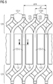
- FIG. 11 shows a radial top view of part of the stator 120 with teeth 122 and winding system 121, which, based on FIG FIG 1 corresponds, for example, to a view oriented radially outward, starting from the plane marked with "V" and represented by the dashed line.
- a stranded rod 123 ' which is positioned in a first groove 126, is connected to a further stranded rod 123 "which is positioned in a second groove 126, seen from the first groove 126, next but one.
- the individual stranded rods 123 are interconnected, in that first sections 123-1 and third sections 123-3 are connected to one another in their respective end regions 123e or on sleeves 123H, for example by soldering or welding Interconnected stranded rods 123 ', 123 "are further arranged in such a way that stranded rods 123 following one another in the series connection are offset from one another in the radial direction, so that, for example, the end region 123e of the second 123" of these two stranded rods 123 is below the end region 123e of the first 123 'of these two stranded rods 123 is positioned.
- the end faces of the sleeves 123H facing one another in the end regions 123e are, as mentioned, for example, soldered to one another.
- the stranded rods connected one behind the other in the series connection would therefore lie alternately above and below in the respective groove 126. If more than two stranded rods 123 are provided for each groove 126, a step-like arrangement of stranded rods 123 would result from groove to groove, in which the next stranded rod 123 in the direction of the series connection is arranged one level lower or higher than the previous one.
- the first and third sections 123-1, 123-3 form the end windings 129 of the stator winding system 121.
- the stranded rods 123 are preformed in an S-shape as described, so that in particular their end regions 123e, with which they are electrical contact can be made with further stranded wire rods 123, having displacements dT in particular in the tangential direction, both the structural size of the end winding 129 and its complexity can be reduced considerably.
- a number L of stranded wire rods 123 corresponding to the number Z is provided.
- P 2 applies.
- This manufacturing method S of the stator winding system 121 is shown in FIG FIG 6 shown schematically.
- the stranded rods 123 to be provided are initially as in connection with FIG FIG 3 described preformed.
- a known stranded conductor comprising a plurality of insulated individual conductors 123L is provided and processed in such a way that the stranded rod 123 to be produced has a rectangular cross-section.
- the heald rod 123 is preformed such that its end regions 123e are offset in tangential and axial directions with respect to its respective second section 123-2.
- dTN n * dN is an integral multiple of the tangential distance dN between two adjacent grooves 126 of the stator 120, where typically, but not necessarily, n ⁇ 2.
- the end regions 123e are finally, for example, hot-crimped and provided with the sleeves 123H.
- the stator winding system 121 is made from the thus prepared, for example the configurations according to FIG 3 or FIG 4 corresponding stranded rods 123 constructed.
- the stranded rods 123 are inserted into the grooves 126 in a first substep S2-1 of the second method step S2 in such a way that the end regions 123e of those stranded rods 123 that are to be connected in series of the stator winding system 121 lie next to one another with their sleeves 123H, for example . one on top of the other, so that they can be electrically connected to each other in order to finally realize the desired series connection.
- the basis for this was already created during the manufacture and dimensioning of the stranded rods 123, in particular with regard to the dislocations dT.
- two stranded rods 123 are in each case electrically connected to those of their end regions 123e or sleeves 123H before they are inserted into the grooves 126 provided for them connected to one another, which should lie next to one another in the state installed in the stator 120 or in the slots 126 in order to realize the rich circuit.
- a second sub-step S2-2 of the second method step S2 following the first sub-step S2-1 those stranded rods 123 which are one behind the other in the series connection of the stator winding system 121 are electrically connected to one another.
- the optional step S2-0 has taken place and accordingly a large number of electrical connections have already been made, Of course, this does not apply to the existing electrical connections.
- the electrical connections of the adjacent end regions 123e or sleeves 123H can be implemented, for example, by soldering or welding.
- the slot lining 128 can be produced in a third sub-step S2-3 of the second method step S2, for example with the help of a potting process in which the stranded rods are in the groove 126 are cast.
- a synthetic resin or glass fiber reinforced plastic (GRP) for example, can be used as the potting material.
- the stranded rods 123 are potted with the potting material in the corresponding grooves 126 in a manner known per se.
- placeholders can be provided at the corresponding points during casting, for example along the radial surfaces 123o of the stranded rods 123, which are removed after the casting and in particular after the potting material has hardened.
- These placeholders for example designed as Teflon strips, are characterized by minimal adhesion to the surfaces 123o of the stranded rods 123 and to the potting material, so that they can be removed or pulled out after curing without great effort and the cooling channels 127 are formed .
- the winding system was described above by way of example as a stator winding system 121. However, it is conceivable that it is used in a corresponding embodiment additionally or alternatively as a winding system for realizing the magnetic means 112 of the rotor 110.
- the term “active part”, for example, can be introduced so that the stranded rods are ultimately intended to form a winding system for an active part of an electrical machine.
Abstract
Die vorliegende Erfindung betrifft ein Wicklungssystem für eine elektrische Maschine, welches aus zu Litzenstäben geformten Litzenleiter aufgebaut ist, welche zudem derart vorgeformt sind, dass eine einfache Verbindung der einzelnen Litzenstäbe miteinander möglich ist. Die Litzenstäbe können in Nuten der Maschine vergossen sein, wobei beim Vergießen zusätzlich Kühlkanäle geschaffen werden können. Letztlich erlaubt die Konstruktion das Vermeiden von Wechselstromverlusten bei gleichzeitiger effizienter Kühlung.The present invention relates to a winding system for an electrical machine, which is constructed from stranded conductors formed into stranded rods, which are also preformed in such a way that the individual stranded rods can be easily connected to one another. The strand rods can be cast in grooves of the machine, with additional cooling channels being able to be created during casting. Ultimately, the construction allows AC losses to be avoided while cooling efficiently at the same time.
Description
Die vorliegende Erfindung betrifft ein eine hochkompakte Wicklung für eine elektrische Maschine.The present invention relates to a highly compact winding for an electrical machine.
Bei elektrischen Maschinen mit hohen Leistungsdichten müssen Probleme einerseits aufgrund von Wechselstromverlusten und andererseits aufgrund von übermäßiger Erwärmung adressiert werden, um den hocheffizienten Betrieb der Maschine zu gewährleisten.In electrical machines with high power densities, problems on the one hand due to alternating current losses and on the other hand due to excessive heating must be addressed in order to ensure the highly efficient operation of the machine.
Derartige Maschinen werden bei vergleichsweise hohen Drehgeschwindigkeiten bzw. Grundfrequenzen betrieben, bspw. in Größenordnungen von 2,5kHz. Die dementsprechend hohen Wechselstromfrequenzen gehen bekanntermaßen mit Wechselstromverlusten aufgrund von Skin- und Proximityeffekten einher.Such machines are operated at comparatively high rotational speeds or basic frequencies, for example in the order of magnitude of 2.5 kHz. The correspondingly high alternating current frequencies are known to be associated with alternating current losses due to skin and proximity effects.
Um diesen Verlusten entgegen zu wirken, werden die Leiter der Wicklungen des Wicklungssystems des Stators und/oder ggf. des Rotors als Litzenleiter ausgebildet, welche jeweils aus einer Vielzahl von vergleichsweise dünnen Einzeldrähten bzw. -adern bestehen. Die Litzenleiter machen sich den Effekt zu Nutze, dass die Stromverdrängung im Leiter, der bspw. als Kupferleiter ausgebildet sein kann, unterdrückt wird und jede Einzelader den gleichen Strom führt, so dass im Idealfall keine zusätzlichen Stromwärmeverluste entstehen.In order to counteract these losses, the conductors of the windings of the winding system of the stator and / or possibly the rotor are designed as stranded conductors, which each consist of a large number of comparatively thin individual wires or cores. The stranded conductors make use of the effect that the current displacement in the conductor, which can be designed as a copper conductor, for example, is suppressed and each individual wire carries the same current, so that in the ideal case there are no additional heat losses.
Infolge der vielen isolierten Einzeladern an Stelle eines massiven Leiters sinkt jedoch der sog. Nutfüllfaktor, welcher ein Maß für das Verhältnis von Leitermaterial, bspw. Kupfer, zu nicht leitendem Material, bspw. Luft oder Isoliermaterial, in der jeweiligen Nut darstellt, bspw. ausgedrückt durch den Quotienten aus Leiterquerschnittsfläche und Nutquerschnittsfläche, und die regulären Stromwärmeverluste steigen an.As a result of the many isolated individual wires instead of a solid conductor, however, the so-called slot fill factor, which is a measure of the ratio of conductor material, e.g. copper, to non-conductive material, e.g. air or insulating material, in the respective slot, e.g. expressed by the quotient of the conductor cross-sectional area and the slot cross-sectional area, and the regular current heat losses increase.
Eine Verbesserung des Nutfüllfaktors kann durch eine vorhergehende Profilierung des Leiters erreicht werden, welcher in diesem Fall geordnet in die Nut eingebracht ist, so dass sich eine verbesserte Ausnutzung der Nutquerschnittsfläche ergibt. Im Wickelkopfbereich, in dem der Leiter von einer Nut in die entsprechend nächste Nut überführt wird und dabei seine Erstreckungsrichtung um 180° ändern muss, ergibt sich bei Verwendung eines Litzenleiters jedoch das Problem eines Auffächerns der Litze in der entsprechenden 180°-Biegung. Dies führt dazu, dass ein regelmäßiger Wickelkopfaufbau erschwert und der Bauraumbedarf für den Wickelkopf erheblich vergrößert wird.An improvement in the slot filling factor can be achieved by a previous profiling of the conductor, which in this case is introduced into the slot in an orderly manner, so that an improved utilization of the slot cross-sectional area results. In the winding head area, in which the conductor is transferred from one slot to the corresponding next slot and thereby has to change its direction of extension by 180 °, the problem arises when using a stranded conductor that the strand is fanned out in the corresponding 180 ° bend. As a result, a regular winding head structure is made more difficult and the space requirement for the winding head is increased considerably.
Diese bei der Verwendung von Litzenleitern auftretenden Probleme können durch Verwendung von Formstabwicklungen vermieden werden. Formstabwicklungen herkömmlicher Art, bspw. vom "Hair-Pin"- oder "I-Pin"-Typ, können aus profilierten Kupferleitern bzw. Kupferstäben hergestellt sein und ermöglichen einen hohen Nutfüllfaktor, einen regelmäßigen Aufbau und definierte Abstände. Ein weiterer Vorteil von Formstabwicklungen ist deren regelmäßiger Aufbau sowie die dadurch ermöglichten kurzen Wickelköpfe. Formstabwicklungen weisen jedoch aufgrund der Verwendung massiver Leiter den wesentlichen Nachteil auf, dass bei höheren Frequenzen die Wechselstromverluste infolge der Stromverdrängung stark zunehmen, wobei zudem die Leiter in Luftspaltnähe stärker erhitzt werden als diejenigen am Nutgrund.These problems that occur when using stranded conductors can be avoided by using form bar windings. Form bar windings of the conventional type, for example of the "hair-pin" or "I-pin" type, can be made from profiled copper conductors or copper rods and enable a high slot filling factor, a regular structure and defined spacing. Another advantage of shaped bar windings is their regular structure and the short winding heads that this enables. Due to the use of solid conductors, however, form bar windings have the significant disadvantage that at higher frequencies the alternating current losses increase sharply due to the current displacement, with the conductors in the vicinity of the air gap being heated more than those at the bottom of the slot.
Diese inhomogene Verlustverteilung stellt ein zusätzliches Problem dar welches durch entsprechende Kühlung adressiert werden muss. Wie einleitend erwähnt stellt die Kühlung der hochleistungsdichten elektrischen Maschinen bzw. die Entwärmung des Leiters ohnehin eine eigene Problematik dar, da Kühlmittel ggf. nicht ideal mit dem Leiter wechselwirken kann, so dass mit erheblichen Verlusten zu rechnen und/oder ein eingeschränkter Betrieb bei entsprechend reduzierter Leistung notwendig wird.This inhomogeneous distribution of losses represents an additional problem which has to be addressed by appropriate cooling. As mentioned in the introduction, the cooling of the high-performance sealed electrical machines or the heat dissipation of the conductor is a problem of its own, since the coolant may not interact ideally with the conductor, so that considerable losses can be expected and / or limited operation with correspondingly reduced Performance becomes necessary.
Es ist daher eine Aufgabe der vorliegenden Erfindung, eine Möglichkeit anzugeben, eine elektrische Maschine mit hoher Leistungsdichte mit geringen Verlusten zu betreiben.It is therefore an object of the present invention to provide a possibility of operating an electrical machine with high power density with low losses.
Diese Aufgabe wird mit Hilfe des in Anspruch 1 beschriebenen Litzenstabes, mit Hilfe des in Anspruch 8 eingeführten Wicklungssystems bestehend aus derartigen Litzenstäben und durch das in Anspruch 10 beschriebene Herstellverfahren gelöst. Die Unteransprüche beschreiben vorteilhafte Ausgestaltungen.This object is achieved with the aid of the stranded rod described in
Ein aus einem Litzenleiter mit einer Vielzahl von Einzelleitern gebildeter Litzenstab weist einen ersten, einen zweiten und einen dritten Abschnitt auf, wobei der zweite Abschnitt in der axialen Erstreckungsrichtung des Litzenstabs zwischen dem ersten und dem dritten Abschnitt angeordnet ist. An den beiden Enden des Litzenstabes, d.h. im ersten und dritten Abschnitt des Litzenstabes, d.h. am jeweiligen vom zweiten Abschnitt abgewandten Ende des ersten und dritten Abschnitts, befinden sich Endbereiche des Litzenstabes. Der Litzenstab ist nun derart vorgeformt, dass er über seine gesamte Länge inklusive der Endbereiche einen in Erstreckungsrichtung bzw. axialer Richtung gesehen rechteckigen Querschnitt aufweist. Dabei ist der zweite Abschnitt gerade und erstreckt sich in axialer Richtung. Dagegen sind die im ersten und dritten Abschnitt angeordneten Endbereiche gegenüber dem zweiten Abschnitt in tangentialer Richtung und in axialer Richtung versetzt. Dieser Aufbau des Litzenstabes bewirkt zum Einen die Reduzierung von Wechselstromverlusten. Der rechteckige Querschnitt ermöglicht zum Einen eine ideale Nutausfüllung. Zum Anderen bieten die damit geschaffenen planen Oberflächen des Litzenstabes eine maximale Fläche zur Wechselwirkung mit einem Kühlmittel.A stranded rod formed from a stranded conductor with a multiplicity of individual conductors has a first, a second and a third section, the second section being arranged in the axial extension direction of the stranded rod between the first and the third section. At the two ends of the stranded rod, i.e. in the first and third section of the stranded rod, i.e. at the end of the first and third section facing away from the second section, there are end regions of the stranded rod. The stranded rod is now preformed in such a way that it has a rectangular cross-section over its entire length including the end regions, viewed in the direction of extension or in the axial direction. The second section is straight and extends in the axial direction. In contrast, the end regions arranged in the first and third sections are offset in the tangential direction and in the axial direction with respect to the second section. On the one hand, this structure of the stranded rod reduces alternating current losses. On the one hand, the rectangular cross-section enables ideal groove filling. On the other hand, the flat surfaces of the stranded rod created in this way offer a maximum area for interaction with a coolant.
Um die Versetzungen der Endbereiche gegenüber dem zweiten Abschnitt zu realisieren sind der erste sowie der dritte Abschnitt in radialer Draufsicht auf den jeweiligen Litzenstab S-förmig, also doppelt, aber in unterschiedliche Richtungen gebogen. Alternativ zur S-förmigen Ausgestaltung können der erste sowie der dritte Abschnitt jeweils gerade verlaufen und gegenüber dem zweiten Abschnitt jeweils um einen Winkel a mit 90°<a<180° abgewinkelt sein. Beide Alternativen erreichen in vergleichsweise einfacher Umsetzung die Versetzungen der Endbereiche, ohne dass bspw. eine Auffächerung der Litzen zu befürchten ist.In order to realize the offsets of the end areas with respect to the second section, the first and the third section are S-shaped in a radial plan view of the respective stranded rod, that is, bent twice but in different directions. As an alternative to the S-shaped configuration, the first and third sections can each run straight and at an angle α with respect to the second section 90 ° <a <180 ° angled. Both alternatives achieve the offsets of the end areas in a comparatively simple implementation, without fear, for example, of a fanning out of the strands.
Vorteilhafterweise ist ein jeweiliger Litzenstab derart geformt, dass der erste, der zweite und der dritte Abschnitt und damit auch die Endbereiche im Wesentlichen in einer Ebene liegen, welche sich in tangentialer Richtung und in axialer Richtung erstreckt. Die Lage der Ebene orientiert sich derart an den vier Oberflächen des mit rechteckigem Querschnitt versehenen Litzenstabes, dass zwei dieser Oberflächen, welche selbst parallel zueinander sind, parallel zur Ebene sind. Diese Geometrie erlaubt in der Folge einen einfachen Aufbau eines Wicklungssystems.A respective stranded rod is advantageously shaped in such a way that the first, the second and the third section and thus also the end regions lie essentially in a plane which extends in the tangential direction and in the axial direction. The position of the plane is based on the four surfaces of the heald rod provided with a rectangular cross-section in such a way that two of these surfaces, which are themselves parallel to one another, are parallel to the plane. This geometry then allows a simple construction of a winding system.
In den Endbereichen der Litzenstäbe können elektrisch leitfähige Hülsen vorgesehen sein, welche die in den Endbereichen des Litzenstabes endenden Einzelleiter des jeweiligen Litzenstabes umfassen, wobei ein elektrischer Kontakt zwischen Einzelleitern und jeweiliger Hülse bewirkt ist. Das Vorsehen der Hülsen in den Endbereichen ermöglicht eine einfache Kontaktierung verschiedener Litzenstäbe miteinander und bewirkt desweiteren eine Fixierung der Einzelleiter, so dass die kompaktierte Form des Litzenstabes beibehalten wird.In the end regions of the stranded rods, electrically conductive sleeves can be provided which enclose the individual conductors of the respective stranded rod ending in the end regions of the stranded rod, with electrical contact being effected between the individual conductors and the respective sleeve. The provision of the sleeves in the end areas enables simple contacting of different stranded rods with one another and also causes the individual conductors to be fixed, so that the compacted shape of the stranded rod is retained.
Die Versetzungen dA, dT sind derart dimensioniert, dass die Endbereiche eines Litzenstabes bzgl. des geometrischen Mittelpunktes des zweiten Abschnitts punktsymmetrisch zueinander angeordnet sind. Diese regelmäßige und symmetrische Dimensionierung der Litzenstäbe erlaubt einen einfachen Aufbau des Wicklungssystems.The offsets dA, dT are dimensioned in such a way that the end regions of a stranded rod are arranged point-symmetrically to one another with respect to the geometric center of the second section. This regular and symmetrical dimensioning of the stranded rods allows a simple construction of the winding system.
Ein entsprechendes Wicklungssystem für ein Aktivteil, bspw. für einen Stator oder für einen Rotor, einer elektrischen Maschine ist aus einer Vielzahl derartiger Litzenstäbe aufgebaut. Dabei sind zumindest die Litzenstäbe einer Teilmenge der Litzenstäbe eine Reihenschaltung bildend hintereinander geschaltet. Die Litzenstäbe einer oder mehrerer weiterer Teilmengen der Vielzahl von Litzenstäben können dementsprechend eine oder mehrere weitere Reihenschaltungen bildend hintereinander geschaltet sein. Im Folgenden wird lediglich auf eine dieser Teilmengen eingegangen, wobei die hierfür ausgeführten Erläuterungen in analoger Weise auch für eventuelle andere Teilmengen gelten.A corresponding winding system for an active part, for example for a stator or for a rotor, of an electrical machine is constructed from a large number of such stranded rods. In this case, at least the stranded rods of a subset of the stranded rods are connected in series, one behind the other switched. The stranded rods of one or more further subsets of the multiplicity of stranded rods can accordingly be connected one behind the other to form one or more further series connections. In the following, only one of these subsets is dealt with, the explanations given for this also apply in an analogous manner to any other subsets.
Zur Erzeugung einer Reihenschaltung werden insbesondere die Endbereiche der Litzenstäbe bzw. die dort ggf. angeordneten Hülsen elektrisch miteinander verbunden, wobei einer der Endbereiche eines ersten Litzenstabes der Reihenschaltung mit einem der Endbereiche des in der Reihenschaltung hinter den ersten Litzenstab zu schaltenden weiteren Litzenstabes elektrisch verbunden wird.To create a series connection, in particular the end areas of the stranded rods or the sleeves possibly arranged there are electrically connected to one another, one of the end areas of a first stranded rod of the series connection being electrically connected to one of the end areas of the further stranded rod to be connected in the series behind the first stranded rod .
Für einen jeweiligen Litzenstab ist zumindest ein Kühlkanal zum Leiten eines Kühlmittels zur Kühlung dieses Litzenstabes vorgesehen. Der Kühlkanal verläuft idealerweise an einer der vier radialen bzw. tangentialen Oberflächen des jeweiligen Litzenstabes insbesondere in axialer Richtung. Wie bereits erwähnt stehen aufgrund des rechteckigen Querschnitts vergleichsweise große Oberflächen zur Wechselwirkung mit dem Kühlmittel zur Verfügung, so dass eine effiziente Kühlung ermöglicht ist.For each stranded rod, at least one cooling channel is provided for conducting a coolant for cooling this stranded rod. The cooling channel ideally runs on one of the four radial or tangential surfaces of the respective stranded rod, in particular in the axial direction. As already mentioned, due to the rectangular cross section, comparatively large surfaces are available for interaction with the coolant, so that efficient cooling is made possible.
Die zweiten Abschnitte der Litzenstäbe können ausgebildet sein, um in Nuten des Aktivteils positioniert zu werden, während die ersten und dritten Abschnitte konsequenterweise in axialer Richtung aus der jeweiligen Nut heraus ragen. Das Wicklungssystem umfasst für jede der Nuten eine Nutauskleidung, in die die Litzenstäbe bzw. deren zweite Abschnitte eingelegt sind, wobei die Nutauskleidung eine oder mehrere Aussparungen zur Bildung eines jeweiligen Kühlkanals aufweist. Es sind somit keine separat anzufertigenden Kühlkanäle notwendig, sondern die Kühlkanäle werden durch die entsprechende Ausgestaltung der Nutverkleidung selbst realisiert. Zur Herstellung eines solchen Wicklungssystems an einem Aktivteil einer elektrischen Maschine wird in einem ersten Verfahrensschritt S1 eine Vielzahl von Litzenstäben bereit gestellt und wie bereits beschrieben derart vorgeformt, dass der jeweilige Litzenstab über seine gesamte Länge inklusive der Endbereiche einen in Erstreckungsrichtung bzw. axialer Richtung gesehen rechteckigen Querschnitt aufweist, dass der zweite Abschnitt gerade ist und sich in axialer Richtung erstreckt und dass die im ersten und im dritten Abschnitt angeordneten Endbereiche gegenüber dem zweiten Abschnitt in tangentialer Richtung und in axialer Richtung versetzt sind. In einem zweiten Verfahrensschritt S2 wird dann das Wicklungssystem aus den vorgeformten Litzenstäben in einfacher Art und Weise aufgebaut.The second sections of the stranded rods can be designed to be positioned in grooves of the active part, while the first and third sections consequently protrude in the axial direction out of the respective groove. For each of the slots, the winding system comprises a slot lining in which the stranded rods or their second sections are inserted, the slot lining having one or more recesses to form a respective cooling channel. It is therefore not necessary to produce cooling channels separately, but rather the cooling channels are implemented by the corresponding design of the groove cladding itself. To produce such a winding system on an active part of an electrical machine, a large number of stranded rods are provided in a first process step S1 and, as already described, are preformed in such a way that the respective stranded rod is rectangular over its entire length, including the end regions, viewed in the direction of extension or in the axial direction Has cross section that the second section is straight and extends in the axial direction and that the end regions arranged in the first and in the third section are offset in the tangential direction and in the axial direction with respect to the second section. In a second method step S2, the winding system is then built up in a simple manner from the preformed stranded wire rods.
Im ersten Verfahrensschritt zum Vorformen eines jeweiligen Litzenstabes wird in einem ersten Teilschritt S1-1 des ersten Verfahrensschrittes S1 ein eine Vielzahl von isolierten Einzelleitern umfassender Litzenleiter einer bestimmten Länge bereitgestellt und zur Bildung des Litzenstabes zunächst über seine gesamte Länge mit einem rechteckigen Querschnitt versehen. In einem zweiten Teilschritt S1-2 des ersten Verfahrensschrittes S1 wird der so im ersten Teilschritt S1-1 gebildete Litzenstab unter Beibehaltung des rechteckigem Querschnitts dahin gehend gebogen, dass seine Endbereiche gegenüber seinem jeweiligen zweiten Abschnitt in tangentialer und in axialer Richtung versetzt sind. Insbesondere die hierbei gewählten tangentialen Versetzungen dT werden bspw. mit dT=dTN/2 in Abhängigkeit von den tangentialen Abständen dTN derjenigen Nuten vorgegeben, in denen in der Reihenschaltung des Wicklungssystems hintereinander zu schaltende Litzenstäbe positioniert werden sollen.In the first process step for preforming a respective stranded rod, in a first sub-step S1-1 of the first process step S1, a large number of insulated individual conductors of a certain length is provided and initially provided with a rectangular cross-section over its entire length to form the stranded rod. In a second sub-step S1-2 of the first method step S1, the stranded rod formed in the first sub-step S1-1 is bent while maintaining the rectangular cross-section so that its end areas are offset in tangential and axial directions compared to its respective second section. In particular, the tangential displacements dT selected here are specified, for example, with dT = dTN / 2 depending on the tangential distances dTN of those slots in which stranded rods to be connected one behind the other are to be positioned in the series connection of the winding system.
In einem dritten Teilschritt S1-3 des ersten Verfahrensschrittes S1 werden nach dessen zweiten Teilschritt S1-2 in jedem der Endbereiche eines jeweiligen Litzenstabes die dortigen Einzelleiter elektrisch miteinander verbunden, bspw. durch Heißcrimpen. Die so gebildeten Gesamtkontakte werden jeweils mit einer elektrisch leitfähigen Hülse versehen und elektrisch kontaktiert. Diese Vorbereitung erlaubt letztlich eine vergleichsweise wenig aufwändige Erstellung der Reihenschaltung durch elektrische Kontaktierung entsprechender Litzenstäbe.In a third sub-step S1-3 of the first method step S1, after its second sub-step S1-2, the individual conductors there are electrically connected to one another in each of the end regions of a respective stranded rod, for example by hot crimping. The overall contacts formed in this way are each provided with an electrically conductive sleeve and electrically contacted. This preparation ultimately allows a comparatively little complex creation of the series connection by making electrical contact with corresponding stranded rods.
Die vorgeformten Litzenstäbe werden in einem ersten Teilschritt S2-1 des zweiten Verfahrensschrittes S2 derart in Nuten des Aktivteils eingelegt, dass jeweils einer der Endbereiche derjenigen Litzenstäbe, die in der Reihenschaltung des Wicklungssystems hintereinander geschaltet sein sollen, mit ihren Hülsen beieinander liegen, bspw. übereinander, so dass sie direkt, d.h. insbesondere ohne nennenswerte mechanische Beanspruchung wie bspw. Verbiegungen oder Verformungen, elektrisch miteinander verbunden werden können, um schließlich die angestrebte Reihenschaltung zu realisieren.In a first sub-step S2-1 of the second process step S2, the preformed stranded wire rods are inserted into grooves in the active part in such a way that one of the end areas of those stranded wire rods that are to be connected in series in the series connection of the winding system lie next to one another with their sleeves, for example one on top of the other so that they can be electrically connected to one another directly, that is to say in particular without significant mechanical stress such as, for example, bending or deformation, in order to finally realize the desired series connection.
In einem nach dem ersten Teilschritt S2-1 folgenden zweiten Teilschritt S2-2 des zweiten Verfahrensschrittes S2 werden diejenigen Litzenstäbe, welche in der Reihenschaltung des Wicklungssystems hintereinander liegen, an den beieinander liegenden Endbereichen bzw. Hülsen elektrisch miteinander verbunden.In a second sub-step S2-2 of the second method step S2 following the first sub-step S2-1, those stranded rods that are one behind the other in the series connection of the winding system are electrically connected to one another at the adjacent end regions or sleeves.
In einem optionalen, vor dem ersten Teilschritt S2-1 des zweiten Verfahrensschrittes S2 auszuführenden Zwischenschritt S2-0 können jeweils zwei Litzenstäbe, bevor sie in die für sie vorgesehenen Nuten eingelegt werden, an denjenigen ihrer Endbereiche bzw. Hülsen bereits vorab elektrisch miteinander verbunden werden, welche im in das Aktivteil bzw. in dessen Nuten eingebauten Zustand beieinander liegen sollen, um die Reichenschaltung zu realisieren. Dies bewirkt eine weitere Erleichterung der Montage des Wicklungssystems, da die zur Verbindung nötigen Löt- oder Schweißarbeiten bereits vorab und ohne die am Aktivteil naturgemäß einschränkten Platzverhältnisse ausgeführt werden können. Für den Fall, dass dieser optionale Schritt S2-0 stattgefunden hat und dementsprechend schon eine Vielzahl von elektrischen Verbindungen hergestellt wurde, entfallen im zweiten Teilschritt S2-2 des zweiten Verfahrensschrittes S2 diese Schritte zum elektrischen Verbinden natürlich für die bereits bestehenden elektrischen Verbindungen.In an optional intermediate step S2-0 to be carried out before the first substep S2-1 of the second method step S2, two stranded wire rods can be electrically connected to each other at those of their end regions or sleeves before they are inserted into the grooves provided for them, which should lie next to each other when installed in the active part or in its grooves in order to realize the realm connection. This further facilitates the assembly of the winding system, since the soldering or welding work required for the connection can already be carried out in advance and without the naturally restricted space available on the active part. In the event that this optional step S2-0 has taken place and accordingly a large number of electrical connections have already been made, the second sub-step S2-2 does not apply to the second Process step S2 these steps for electrical connection, of course, for the already existing electrical connections.
Die Litzenstäbe können in Nutauskleidungen der Nuten des Aktivteils eingelegt werden, wobei eine jeweilige Nutauskleidung mit Hilfe eines Vergussverfahrens hergestellt wird, bei dem jeweils ein oder mehrere Litzenstäbe in die Nut eingelegt und dort zur Bildung der jeweiligen Nutauskleidung mit einem Vergussmaterial vergossen werden. Die jeweilige Nutauskleidung weist für zumindest einen dort vergossenen Litzenstab einen Kühlkanal in Form einer Aussparung zum Leiten eines Kühlmittels zum Kühlen des Litzenstabes auf. Die jeweilige Aussparung wird geschaffen, indem beim Vergießen im Bereich des zu kühlenden Litzenstabs an dem Ort, an dem das Kühlmittel mit dem zu kühlenden Litzenstab wechselwirken soll, also bspw. entlang einer radialen oder tangentialen Oberfläche des Litzenstabes, ein Platzhalter positioniert wird, welcher nach dem Vergießen und insbesondere nach Aushärtung des Vergussmaterials entfernt wird, so dass der jeweilige Kühlkanal als Aussparung bzw. Hohlraum zurück bleibt. Dementsprechend lässt sich in einfacher Art und Weise ein Kühlsystem für das Wicklungssystem aufbauen.The stranded rods can be inserted into the slot linings of the grooves of the active part, a respective slot lining being produced with the aid of a potting process in which one or more stranded rods are inserted into the groove and encapsulated there with a potting material to form the respective slot lining. The respective groove lining has a cooling channel in the form of a recess for guiding a coolant for cooling the stranded rod for at least one stranded rod encapsulated there. The respective recess is created by positioning a placeholder in the area of the stranded rod to be cooled at the place where the coolant is to interact with the stranded rod to be cooled, for example along a radial or tangential surface of the stranded rod after the potting and in particular after the potting material has hardened, so that the respective cooling channel remains as a recess or cavity. Accordingly, a cooling system for the winding system can be set up in a simple manner.
Im Folgenden werden die Erfindung und beispielhafte Ausführungsformen anhand von Zeichnungen näher erläutert. Dort werden gleiche Komponenten in verschiedenen Figuren durch gleiche Bezugszeichen gekennzeichnet. Es ist daher möglich, dass sich bei der Beschreibung einer zweiten Figur zu einem bestimmten Bezugszeichen, welches bereits im Zusammenhang mit einer anderen, ersten Figur erläutert wurde, keine näheren Erläuterungen finden. In einem solchen Fall kann bei der Ausführungsform der zweiten Figur davon ausgegangen werden, dass die dort mit diesem Bezugszeichen gekennzeichnete Komponente auch ohne nähere Erläuterung im Zusammenhang mit der zweiten Figur die gleichen Eigenschaften und Funktionalitäten aufweist, wie im Zusammenhang mit der ersten Figur erläutert. Desweiteren werden der Übersichtlichkeit wegen teilweise nicht sämtliche Bezugszeichen in sämtlichen Figuren dargestellt, sondern nur diejenigen, auf die in der Beschreibung der jeweiligen Figur Bezug genommen wird.The invention and exemplary embodiments are explained in more detail below with reference to drawings. There, the same components in different figures are identified by the same reference symbols. It is therefore possible that, in the description of a second figure, no more detailed explanations can be found for a specific reference number which has already been explained in connection with another, first figure. In such a case, in the embodiment of the second figure, it can be assumed that the component identified there with this reference symbol has the same properties and functionalities as explained in connection with the first figure, even without further explanation in connection with the second figure. Furthermore, for the sake of clarity, some not all reference symbols are shown in all figures, but only those to which reference is made in the description of the respective figure.
Es zeigen:
- FIG 1
- einen einen Rotor und einen Stator darstellenden Ausschnitt einer aus dem Stand der Technik bekannten elektrischen Maschine,
- FIG 2
- eine Nut mit dort befindlichem Leiter des Statorwicklungssystems der Maschine,
- FIG 3
- einen Litzenstab in einer ersten Ausführung,
- FIG 4
- eine Litzenstab in einer zweiten Ausführung,
- FIG 5
- eine radiale Draufsicht auf einen Ausschnitt eines Statorwicklungssystems bestehend aus den Litzenstäben,
- FIG 6
- ein Verfahren zur Herstellung eines Statorwicklungssystems.
- FIG 1
- a section representing a rotor and a stator of an electrical machine known from the prior art,
- FIG 2
- a slot with the conductor of the machine's stator winding system located there,
- FIG 3
- a stranded rod in a first version,
- FIG 4
- a stranded rod in a second version,
- FIG 5
- a radial top view of a section of a stator winding system consisting of the stranded rods,
- FIG 6
- a method of manufacturing a stator winding system.
Es sei angemerkt, dass sich Begriffe wie "axial", "radial", "tangential" etc. auf die in der jeweiligen Figur bzw. im jeweils beschriebenen Beispiel zum Einsatz kommende Drehachse des Rotors beziehen. Mit anderen Worten beziehen sich die Richtungen axial, radial, tangential stets auf eine Drehachse des Rotors und damit auf die entsprechende Symmetrieachse des Stators. Dabei beschreibt "axial" eine Richtung parallel zur Achse, "radial" beschreibt eine Richtung orthogonal zur Achse, auf diese zu oder auch von ihr weg, und "tangential" ist eine Richtung, die in konstantem radialen Abstand zur Achse und bei konstanter Axialposition kreisförmig um die Achse herum gerichtet ist. Der Ausdruck "in Umfangsrichtung" ist mit "tangential" gleichzusetzen. Insbesondere sollen sich Begriffe wie "oben", "unten", "über", "unter", "auf" etc. auf die radiale Richtung beziehen und unabhängig von der Richtung der Gravitationswirkung sein.It should be noted that terms such as “axial”, “radial”, “tangential” etc. relate to the axis of rotation of the rotor used in the respective figure or in the example described in each case. In other words, the directions axial, radial, tangential always relate to an axis of rotation of the rotor and thus to the corresponding axis of symmetry of the stator. "Axial" describes a direction parallel to the axis, "radial" describes a direction orthogonal to the axis, towards or away from it, and "tangential" is a direction that is circular at a constant radial distance from the axis and at a constant axial position is directed around the axis. The expression "in the circumferential direction" is to be equated with "tangential". In particular, terms such as “above”, “below”, “above”, “below”, “on” etc. should relate to the radial direction and be independent of the direction of the gravitational effect.
Im Bezug auf eine Fläche, bspw. eine Querschnittsfläche, beschreiben die Begriffe "axial", "radial", "tangential" etc. die Orientierung des Normalenvektors der Fläche, d.h. desjenigen Vektors, der senkrecht auf der betroffenen Fläche steht.In relation to an area, for example a cross-sectional area, the terms "axial", "radial", "tangential" etc. the orientation of the normal vector of the surface, ie that vector which is perpendicular to the surface concerned.
Der Begriff "benachbart" soll im Zusammenhang mit Bauteilen, bspw. mit Spulen oder Statorzähnen, ausdrücken, dass sich im Falle von "benachbarten Bauteilen" zwischen diesen beiden Bauteilen insbesondere kein weiteres derartiges Bauteil befindet, sondern höchstens ein leerer Zwischenraum oder ggf. ein andersartiges Bauteil.In connection with components, for example with coils or stator teeth, the term "adjacent" is intended to express that in the case of "adjacent components" there is in particular no other such component between these two components, but at most an empty space or possibly a different one Component.
Der Übersichtlichkeit wegen werden in den Figuren teilweise in den Fällen, in denen Bauteile mehrfach vorhanden sind, häufig nicht sämtliche dargestellten Bauteile mit Bezugszeichen versehen.For the sake of clarity, in some cases in the figures in which components are present several times, not all of the components shown are provided with reference symbols.
Schließlich verweisen an entsprechenden Pfeilen und gestrichelten Linien vorgesehenen römischen Zahlen auf die den römischen Zahlen entsprechenden Figuren, wobei diese entsprechenden Figuren den Blick auf die durch die gestrichelte Linie markierte Ebene bzw. den korrespondierenden Querschnitt in der durch den Pfeil vorgegebenen Blickrichtung zeigen.Finally, the Roman numerals provided by the corresponding arrows and dashed lines refer to the figures corresponding to the Roman numerals, these corresponding figures showing the view of the plane marked by the dashed line or the corresponding cross section in the viewing direction given by the arrow.
Die
Der Elektromotor 100 weist einen im Wesentlichen ringförmigen bzw. hohlzylindrischen Stator 120 sowie einen hier exemplarisch als Innenläufer ausgebildeten, im Wesentlichen zylindrischen Rotor 110 auf, wobei der Rotor 110 innerhalb des Stators 120 und konzentrisch zu dieser angeordnet ist und im Betriebszustand des Elektromotors 100 um eine Rotationsachse rotiert. Dabei bilden Rotor 110 und Stator 120 einen zwischen ihnen liegenden Luftspalt 150 aus. Der Rotor 110 weist erste magnetische Mittel 112 auf, die bspw. als Permanentmagnete 112 ausgebildet und an einer dem Stator 120 zugewandten Oberfläche des Rotors 110 angeordnet sein können. Dies ist in
Der Stator 120 weist eine Vielzahl von einzelnen Statorzähnen 122 sowie zweite magnetische Mittel 121 auf, die bspw. als elektrische Leiter 121' eines Statorwicklungssystems 121 realisiert sein können. In
Die Leiter 121' sind jeweils im Bereich des Zahnhalses 122h eines jeweiligen Zahnes 122 zwischen dessen Zahnfuß 122f und Zahnkopf 122k angeordnet. Demnach befinden sich in einer jeweiligen Statornut 126 zwischen zwei in tangentialer Richtung benachbarten Statorzähnen 122 Abschnitte 121'-2 der zwischen diesen beiden Statorzähnen 122 angeordneten Leiter 121', während weitere, jedoch nicht dargestellte Abschnitte der Leiter 121' die sogenannten Wickelköpfe 129 des Statorwicklungssystems bilden. Diese sind in
Um die in einer jeweiligen Nut 126 befindlichen Abschnitte 121'-2 der jeweiligen Leiter 121' vor Beschädigungen zu schützen und um insbesondere sicher zu stellen, dass die Wicklungen 121 an Ort und Stelle verbleiben und in radialer Richtung nicht verrutschen, können bspw. als Nutverschlusskeile ausgebildete Nutverschlüsse 124 vorgesehen sein. Diese sind zwischen zwei benachbarten Statorzähnen 122 im Bereich der Zahnköpfe 122k dieser Zähne 122 angeordnet und verschließen die zwischen diesen Zähnen 122 gebildete Statornut 126.In order to protect the sections 121'-2 of the respective conductors 121 'located in a
Die Leiter bzw. zweiten elektrischen Mittel 121' sind im Betriebszustand des Elektromotors 100 von einem elektrischen Strom durchflossen, so dass in bekannter Weise magnetische Felder erzeugt werden. Die ersten und die zweiten magnetischen Mittel 112, 121 sind derart ausgebildet und durch den Luftspalt 150 voneinander beabstandet zueinander angeordnet, dass sie im Betriebszustand des Elektromotors 100 elektromagnetisch miteinander wechselwirken. Dieses Konzept einschließlich der Bedingungen für die Ausbildung und genaue Anordnung der magnetischen Mittel 112, 121 bzw. von Rotor 110 und Stator 120 sind an sich bekannt und werden daher im Folgenden nicht näher erläutert. Es sei lediglich erwähnt, dass zum Betreiben der elektrischen Maschine 100 als Elektromotor das Statorwicklungssystem 121 bzw. dessen Leiter 121' mit Hilfe einer lediglich schematisch angedeuteten Stromquelle 200 mit den genannten elektrischen Strömen beaufschlagt werden, die bewirken, dass die Leiter 121' dementsprechende Magnetfelder erzeugen, welche mit den Magnetfeldern der Permanentmagnete 112 des Rotors 110 in elektromagnetische Wechselwirkung treten. Dies resultiert darin, dass auf die Permanentmagnete 112 ein Drehmoment in einer tangentialen Richtung bzw. Umfangsrichtung wirkt, welches unter der Voraussetzung, dass die Permanentmagnete 112 ausreichend fest mit dem Rotorgrundkörper 111 verbunden sind, darin resultiert, dass bei geeigneter Ausbildung und Anordnung der genannten Komponenten zueinander der Rotor 110 und mit ihm die Welle in Rotation versetzt werden.In the operating state of the
Die Stromquelle 200 umfasst eine elektrische Energiequelle 210, bspw. eine Batterie oder einen elektrischen Generator, und eine Leistungselektronik 220, die die von der Energiequelle 210 bereit gestellte elektrische Energie über die mit der gestrichelten Linie 230 angedeutete elektrische Verbindung in das momentan vom Elektromotor 100 zum Erbringen der bspw. von einem Betreiber des Systems 1 angeforderten Leistung benötigte Strom-/Spannungssignal wandelt.The
Dieses auf der elektromagnetischen Wechselwirkung fußende Konzept der Ausbildung der elektrischen Maschine 100 als Elektromotor kann als bekannt vorausgesetzt werden. Auch die alternative Konfiguration und Verwendung der elektrischen Maschine 100 als Generator kann als bekannt vorausgesetzt werden. In letzterem Betriebsmodus ist in der
Wie einleitend erwähnt ist insbesondere bei hochleistungsdichten Maschinen 100 der Abtransport der im Betrieb am Leiter 121' entstehenden Wärme essentiell. Hierzu werden in der hier offenbarten elektrischen Maschine Kühlkanäle 127 vorgesehen, deren Ausbildung und Anordnung in
Die
Sowohl zwischen den Abschnitten 123-2 als auch zwischen jeweiligem Abschnitt 123-2 und Nutwand 126w bzw. Nutverschluss 124 sind Kühlkanäle 127 angeordnet, welche in axialer Richtung, also entlang und parallel zu den Abschnitten 123-2 verlaufen. Dadurch, dass die Abschnitte 123-2 einen rechteckigen, vorzugsweise quadratischen Querschnitt aufweisen, ist die Berührfläche zwischen Kühlkanal 127 und jeweiligem Leiter 121' bzw. 123-2 und damit die Kühlwirkung maximal. Insbesondere erlaubt diese Anordnung vorteilhafterweise eine direkte Kühlung des jeweiligen Leiters 121' bzw. 123-2.Cooling
Der Gesamtleiter 121' des Statorwicklungssystems 121 besteht aus einer Vielzahl von in Reihe geschalteten Litzenstäben 123, welche wie in der
Durch die S-förmige Ausgestaltung der Abschnitte 123-1, 123-3 sind also die Endbereiche 123e gegenüber dem jeweiligen zweiten Abschnitt 123-2 zum Einen in axialer Richtung A und zum Anderen in tangentialer Richtung T versetzt. Die Versetzungen dA, dT sind derart dimensioniert, dass zum Einen die Endbereiche 123e eines Litzenstabes 123 bzgl. des Mittelpunktes des zweiten Abschnitts 123-2 punktsymmetrisch zueinander angeordnet sind. Zum Anderen sind insbesondere die tangentialen Versetzungen dT abhängig vom tangentialen Abstand dTN der Statornuten 126, in denen miteinander zu verbindenden Litzenstäbe angeordnet werden sollen. Vorzugsweise gilt dT=dTN/2, so dass die beiden tangentialen Versetzungen dT der beiden Litzenstäbe 123, sobald sie miteinander verbunden sind, in Summe gerade dem tangentialen Abstand der Nuten 126 entsprechen, in denen die betroffenen Litzenstäbe 123 positioniert werden sollen. Schließlich gilt, dass sich die Abschnitte 123-1, 123-2, 123-3 eines jeweiligen Litzenstabes 123 in einer Ebene erstrecken, wobei diese Ebene desweiteren parallel zu zweien der sich gegenüberliegenden Seitenflächen des Litzenstabes 123 liegt, welcher wie bereits erwähnt einen rechteckigen Querschnitt aufweist. Wenn der Litzenstab 123 in den Stator 120 eingebaut bzw. in der Nut 126 positioniert ist, erstreckt sich diese Ebene in tangentialer sowie in axialer Richtung.Due to the S-shaped configuration of the sections 123-1, 123-3, the
Die so beschriebenen Versetzungen dA, dT der Endbereiche 123e sowie die Punktsymmetrie können auch dadurch erreicht werden, dass anstelle der S-förmigen Ausgestaltung gemäß
Ein jeweiliger Litzenstab 123 ist zunächst als Litzenleiter ausgebildet, besteht also aus einer Vielzahl von jeweils insolierten Einzelleitern 123L. Dies ist in
Im Anschluss werden die Litzenstäbe 123 derart gebogen, dass die beschriebenen S-förmigen Abschnitte 123-1, 123-3 entstehen. Dabei kann es durchaus zu gegenseitigen Verschiebungen der Einzelleiter 123L des Litzenleiters bzw. -stabes 123 in deren Erstreckungsrichtung kommen. Dies ist jedoch zuzulassen, da diese Verschiebungen keinen Einfluss auf die Beibehaltung des rechteckigen Querschnitts haben. Nach Abschluss des Biegevorgangs werden die Litzenstäbe 123 in ihren Endbereichen 123e jeweils heißgecrimpt und dabei mit einer elektrisch leitfähigen Hülse 123H versehen, um zum Einen die Einzelleiterisolation an entsprechenden Stellen zu entfernen und um zum Anderen eine spätere paarweise Kontaktierung zweier Litzenstäbe 123 mit großer Berührfläche zu ermöglichen.The stranded
Bei dieser Kompaktierung und elektrischen Kontaktierung der an sich isolierten Einzeldrähte des Litzenleiters an den beiden Enden 123e des so vorgeformten Litzenstabes 123 entsteht eine rechtwinklige Kompaktierungszone mit planen Seitenflächen, welche idealerweise größer als der Litzenquerschnitt ist. Die elektrische Verbindung der Einzeladern des Litzenleiters erfolgt erst nach der geometrischen Formgebung zum Litzenstab 123, um bei der Formung wie erwähnt eine Verschiebung einzelner Einzelleiter 123L des Litzenleiters zuzulassen und ein Auffächern zu minimieren.With this compacting and electrical contacting of the insulated individual wires of the stranded conductor at the two ends 123e of the stranded
Die so geformten Litzenstäbe 123 erwirken zum Einen aufgrund der Ausbildung als Litzenleiter die Reduzierung der Wechselstromverluste. Die kompaktierte Form, die sich im rechteckigen Querschnitt niederschlägt, erlaubt desweiteren die maximale Wechselwirkung mit den an den somit planen Seitenflächen eines jeweiligen Litzenstabes 123 gemäß
Die ersten und dritten Abschnitte 123-1, 123-3 bilden die Wickelköpfe 129 des Statorwicklungssystems 121. Je nachdem, wie stark die die S-förmigen Ausgestaltungen der Litzenstäbe 123 in ihren ersten und dritten Abschnitten 123-1, 123-3 verursachenden Krümmungen ausfallen können, ergeben sich mehr oder weniger große axiale Versetzungen dA und damit sich mehr oder weniger in den axialen Richtungen erstreckende Wickelköpfe 129. Dadurch, dass die Litzenstäbe 123 wie beschrieben S-förmig vorgeformt werden, so dass insbesondere ihre Endbereiche 123e, mit denen sie mit weiteren Litzenstäben 123 elektrisch kontaktiert werden können, Versetzungen dT insbesondere in tangentialer Richtung aufweisen, können sowohl die Baugröße des Wickelkopfes 129 als auch seine Komplexität erheblich reduziert werden. Durch die Verwendung von derart vorpräparierten Litzenstäben 123 wird also im Bereich der Wickelköpfe 129 Platz eingespart. Außerdem ist es aufgrund der S-Form nicht nötig, dass ein sonst durchgehendes Zwischenstück im Wickelkopf, welches zwei aufeinander folgende zweite Abschnitte 123-2 verbinden soll, einen Bogen vollzieht, um die 180°-Richtungsänderung von einem zweiten Abschnitt 123-2 zum nächsten zu realisieren. Derartige Bögen waren bislang nicht ohne Auffächerung der sie bildenden Litzenleiter realisierbar. Diese Problematik tritt in der hier vorgegebenen Lösung nicht mehr auf.The first and third sections 123-1, 123-3 form the
Zur Herstellung eines entsprechenden Statorwicklungssystems 121 für einen Stator 120 mit einer Anzahl Z von Nuten 126 wird eine von der Anzahl Z abhängige Anzahl entsprechende Anzahl L von Litzenstäben 123 bereitgestellt. Die Anzahl L hängt dabei von der Anzahl Z sowie von der Anzahl P der in jeder Nut 126 zu platzierenden Litzenstäbe 123 ab, so dass letztlich gilt L=Z*P. Im in der
Dieses Herstellverfahren S des Statorwicklungssystems 121 wird in der
Anschließend wird der Litzenstab 123 in einem zweiten Teilschritt S1-2 des ersten Verfahrensschrittes S1 dahin gehend vorgeformt, dass seine Endbereiche 123e gegenüber seinem jeweiligen zweiten Abschnitt 123-2 in tangentialer und in axialer Richtung versetzt sind. Die hierbei gewählten Versetzungen dT werden bspw. mit dT=dTN/2 in Abhängigkeit von den tangentialen Abständen dTN derjenigen Nuten 126 vorgegeben, in denen in der Reihenschaltung des Statorwicklungssystems 121 hintereinander zu schaltende Litzenstäbe 123 positioniert werden sollen. Dabei ist dTN=n*dN ein ganzzahliges Vielfaches des tangentialen Abstandes dN zweier benachbarter Nuten 126 des Stators 120, wobei typischerweise, aber nicht notwendigerweise n≥2 gilt.Subsequently, in a second sub-step S1-2 of the first method step S1, the
In einem dritten Teilschritt S1-3 des ersten Verfahrensschrittes S1 werden die Endbereiche 123e schließlich bspw. heißgecrimpt und mit den Hülsen 123H versehen.In a third sub-step S1-3 of the first method step S1, the
In einem zweiten Schritt S2 des Herstellverfahrens wird das Statorwicklungssystem 121 aus den so vorbereiteten, bspw. den Ausbildungen gemäß
In einem optionalen, vor dem ersten Teilschritt S2-1 des zweiten Verfahrensschrittes S2 liegenden Zwischenschritt S2-0 werden jeweils zwei Litzenstäbe 123, bevor sie in die für sie vorgesehenen Nuten 126 eingelegt werden, an denjenigen ihrer Endbereiche 123e bzw. Hülsen 123H bereits vorab elektrisch miteinander verbunden, welche im in den Stator 120 bzw. in die Nuten 126 eingebauten Zustand beieinander liegen sollen, um die Reichenschaltung zu realisieren.In an optional intermediate step S2-0 preceding the first sub-step S2-1 of the second method step S2, two stranded
In einem auf den ersten Teilschritt S2-1 folgenden zweiten Teilschritt S2-2 des zweiten Verfahrensschrittes S2 werden diejenigen Litzenstäbe 123, welche in der Reihenschaltung des Statorwicklungssystems 121 hintereinander liegen, elektrisch miteinander verbunden. Für den Fall, dass der optionale Schritt S2-0 stattgefunden hat und dementsprechend schon eine Vielzahl von elektrischen Verbindungen hergestellt wurde, entfällt dies natürlich für die bereits bestehenden elektrischen Verbindungen.In a second sub-step S2-2 of the second method step S2 following the first sub-step S2-1, those stranded
Wie bereits erwähnt können die elektrischen Verbindungen der beieinander liegenden Endbereiche 123e bzw. Hülsen 123H bspw. durch Löten oder Schweißen realisiert werden.As already mentioned, the electrical connections of the
Für den Fall, dass eine Anordnung gemäß
Das Wicklungssystem wurde oben exemplarisch als Statorwicklungssystem 121 beschrieben. Es ist jedoch denkbar, dass es in entsprechender Ausführung zusätzlich oder alternativ als Wicklungssystem zur Realisierung der magnetischen Mittel 112 des Rotors 110 verwendet wird. Um dies zu verallgemeinern kann bspw. der Begriff "Aktivteil" eingeführt werden, so dass die Litzenstäbe letztlich zur Bildung eines Wicklungssystems für ein Aktivteil einer elektrischen Maschine vorgesehen sind.The winding system was described above by way of example as a
- 100100
- elektrische Maschineelectric machine
- 110110
- Rotorrotor
- 112112
- PermanentmagnetPermanent magnet
- 120120
- Statorstator
- 121121
- StatorwicklungssystemStator winding system
- 121'121 '
- Leiterladder
- 121'-2121'-2
- LeiterabschnittLadder section
- 122122
- StatorzahnStator tooth
- 122f122f
- ZahnfußTooth root
- 122h122h
- ZahnhalsTooth neck
- 122k122k
- ZahnkopfTooth head
- 123123
- LitzenstabStranded rod
- 123-1, 123-2, 123-3123-1, 123-2, 123-3
- LitzenstababschnitteStranded rod sections
- 123e123e
- EndbereichEnd area
- 123H123H
- HülseSleeve
- 123L123L
- EinzelleiterSingle conductor
- 123o123o
- LitzenstaboberflächeStranded rod surface
- 124124
- NutverschlussSlot lock
- 125125
- StatorjochStator yoke
- 126126
- StatornutStator slot
- 126w126w
- NutwandGroove wall
- 127127
- KühlkanalCooling duct
- 128128
- Isolierung, Verguss, NutauskleidungInsulation, potting, groove lining
- 129129
- WickelkopfWinding head
- 150150
- LuftspaltAir gap
- 200200
- StromquellePower source
- 210210
- elektrische Energiequelleelectrical energy source
- 220220
- LeistungselektronikPower electronics
- 230230
- elektrische Verbindungelectrical connection
Claims (15)
wobei der Litzenstab (123) derart vorgeformt ist, dass
wherein the stranded rod (123) is preformed such that
Applications Claiming Priority (1)
| Application Number | Priority Date | Filing Date | Title |
|---|---|---|---|
| DE102020208130.1A DE102020208130A1 (en) | 2020-06-30 | 2020-06-30 | Winding system for an electrical machine |
Publications (1)
| Publication Number | Publication Date |
|---|---|
| EP3934067A1 true EP3934067A1 (en) | 2022-01-05 |
Family
ID=76695519
Family Applications (1)
| Application Number | Title | Priority Date | Filing Date |
|---|---|---|---|
| EP21181954.5A Withdrawn EP3934067A1 (en) | 2020-06-30 | 2021-06-28 | Coil system for an electric machine |
Country Status (2)
| Country | Link |
|---|---|
| EP (1) | EP3934067A1 (en) |
| DE (1) | DE102020208130A1 (en) |
Cited By (2)
| Publication number | Priority date | Publication date | Assignee | Title |
|---|---|---|---|---|
| WO2023218044A3 (en) * | 2022-05-13 | 2024-01-11 | Hofer Powertrain Innovation Gmbh | Stator for an electrical machine comprising a compressed strand winding head, corresponding electrical machine, and manufacturing method for a stator |
| WO2024028111A1 (en) * | 2022-08-03 | 2024-02-08 | Magna powertrain gmbh & co kg | Electrical machine |
Citations (5)
| Publication number | Priority date | Publication date | Assignee | Title |
|---|---|---|---|---|
| EP1560313A2 (en) * | 2004-01-27 | 2005-08-03 | General Electric Company | Electrical machine winding formed by Litz wire and with an integrated cooling system |
| WO2015162586A2 (en) * | 2014-04-25 | 2015-10-29 | Brusa Elektronik Ag | Compressed strand, use thereof and method for producing a stator for an electric machine |
| EP3051669A1 (en) * | 2015-01-27 | 2016-08-03 | Brusa Elektronik AG | Winding for a stator, electric machine, and method for manufacturing the winding for a stator |
| WO2019040956A1 (en) * | 2017-08-28 | 2019-03-07 | Miba Aktiengesellschaft | Stator component for an electric machine |
| EP3484021A1 (en) * | 2017-11-13 | 2019-05-15 | Audi Ag | Wall insulation for a stator groove of an electric motor |
-
2020
- 2020-06-30 DE DE102020208130.1A patent/DE102020208130A1/en not_active Withdrawn
-
2021
- 2021-06-28 EP EP21181954.5A patent/EP3934067A1/en not_active Withdrawn
Patent Citations (5)
| Publication number | Priority date | Publication date | Assignee | Title |
|---|---|---|---|---|
| EP1560313A2 (en) * | 2004-01-27 | 2005-08-03 | General Electric Company | Electrical machine winding formed by Litz wire and with an integrated cooling system |
| WO2015162586A2 (en) * | 2014-04-25 | 2015-10-29 | Brusa Elektronik Ag | Compressed strand, use thereof and method for producing a stator for an electric machine |
| EP3051669A1 (en) * | 2015-01-27 | 2016-08-03 | Brusa Elektronik AG | Winding for a stator, electric machine, and method for manufacturing the winding for a stator |
| WO2019040956A1 (en) * | 2017-08-28 | 2019-03-07 | Miba Aktiengesellschaft | Stator component for an electric machine |
| EP3484021A1 (en) * | 2017-11-13 | 2019-05-15 | Audi Ag | Wall insulation for a stator groove of an electric motor |
Cited By (2)
| Publication number | Priority date | Publication date | Assignee | Title |
|---|---|---|---|---|
| WO2023218044A3 (en) * | 2022-05-13 | 2024-01-11 | Hofer Powertrain Innovation Gmbh | Stator for an electrical machine comprising a compressed strand winding head, corresponding electrical machine, and manufacturing method for a stator |
| WO2024028111A1 (en) * | 2022-08-03 | 2024-02-08 | Magna powertrain gmbh & co kg | Electrical machine |
Also Published As
| Publication number | Publication date |
|---|---|
| DE102020208130A1 (en) | 2021-12-30 |
Similar Documents
| Publication | Publication Date | Title |
|---|---|---|
| EP2688183B1 (en) | Cast electric coil | |
| EP1481407B1 (en) | Translator | |
| EP1969697B1 (en) | Electric machine, in particular alternator for a motor vehicle | |
| EP3934067A1 (en) | Coil system for an electric machine | |
| EP3216113B1 (en) | Rotor or stator with short nested winding heads | |
| DE102016202071A1 (en) | Electrical conductor for an electric machine with increased power-to-weight ratio and electrical component for the electric machine | |
| WO2018086983A1 (en) | Electrical coil arrangement comprising litz wire conductor segments | |
| DE102020124089A1 (en) | MODULAR SCALABLE ELECTRIC MACHINE | |
| DE102020101149A1 (en) | Axial flux machine with mechanically fixed stator cores with radially extending sheet metal segments | |
| DE112016005116T5 (en) | WINDING AND STATOR ARRANGEMENT OF AN ELECTROROTORING MACHINE | |
| EP3618236A2 (en) | Permanently excited electric machine | |
| WO2019215097A1 (en) | Mehtod for producing a winding for a stator of an electrical machine and electrical machine | |
| EP2026450B1 (en) | Electric machine with a winding for producing a rotating field and method for producing the winding | |
| DE102020203944A1 (en) | Interconnection unit and method for producing a winding system | |
| EP3311469A1 (en) | Pre-formed coil, winding structure, and stator for a generator of a wind turbine and method for producing a stator | |
| WO2015000639A2 (en) | Machine component for an electric machine with multiple coils | |
| EP3457533B1 (en) | Rotor for an electrical machine | |
| DE102020203945A1 (en) | Stator winding system with serial coil winding | |
| EP3605797A1 (en) | Cogged coil for a stator of an electrically rotating machine | |
| DE202019105598U1 (en) | Stator with optimized winding space | |
| DE10061045A1 (en) | Multi-phase electrical machine | |
| WO2019149508A1 (en) | Rotor comprising cooling channels | |
| DE102010028869A1 (en) | Direct current generator i.e. wind power generator, has stator including single-layer winding system constructed of several winding segments, where each winding segment includes open slots for winding of three stator coils | |
| DE102008008703A1 (en) | Electrical machine i.e. transverse flux machine, for use as e.g. linear drive, has poles encompassing coils, where coils assigned to different phases are arranged, such that coils do not influence circuit assigned to another phase | |
| DE102020207796A1 (en) | PRIMARY PART FOR AN ELECTRICAL MACHINE AND METHOD FOR MANUFACTURING SUCH PRIMARY PART |
Legal Events
| Date | Code | Title | Description |
|---|---|---|---|
| STAA | Information on the status of an ep patent application or granted ep patent |
Free format text: STATUS: UNKNOWN |
|
| PUAI | Public reference made under article 153(3) epc to a published international application that has entered the european phase |
Free format text: ORIGINAL CODE: 0009012 |
|
| STAA | Information on the status of an ep patent application or granted ep patent |
Free format text: STATUS: THE APPLICATION HAS BEEN PUBLISHED |
|
| AK | Designated contracting states |
Kind code of ref document: A1 Designated state(s): AL AT BE BG CH CY CZ DE DK EE ES FI FR GB GR HR HU IE IS IT LI LT LU LV MC MK MT NL NO PL PT RO RS SE SI SK SM TR |
|
| B565 | Issuance of search results under rule 164(2) epc |
Effective date: 20211119 |
|
| STAA | Information on the status of an ep patent application or granted ep patent |
Free format text: STATUS: THE APPLICATION IS DEEMED TO BE WITHDRAWN |
|
| 18D | Application deemed to be withdrawn |
Effective date: 20220706 |