EP3051669A1 - Bobine pour un stator, machine électrique, et procédé de fabrication de la bobine pour un stator - Google Patents
Bobine pour un stator, machine électrique, et procédé de fabrication de la bobine pour un stator Download PDFInfo
- Publication number
- EP3051669A1 EP3051669A1 EP15152755.3A EP15152755A EP3051669A1 EP 3051669 A1 EP3051669 A1 EP 3051669A1 EP 15152755 A EP15152755 A EP 15152755A EP 3051669 A1 EP3051669 A1 EP 3051669A1
- Authority
- EP
- European Patent Office
- Prior art keywords
- stator
- winding
- sleeves
- sleeve
- shaped
- Prior art date
- Legal status (The legal status is an assumption and is not a legal conclusion. Google has not performed a legal analysis and makes no representation as to the accuracy of the status listed.)
- Granted
Links
- 238000004804 winding Methods 0.000 title claims abstract description 58
- 238000000034 method Methods 0.000 title claims description 52
- 238000004519 manufacturing process Methods 0.000 title claims description 16
- 239000004020 conductor Substances 0.000 claims abstract description 12
- 238000003466 welding Methods 0.000 claims description 17
- 238000007493 shaping process Methods 0.000 claims description 10
- 238000005520 cutting process Methods 0.000 claims description 6
- 238000005476 soldering Methods 0.000 claims description 6
- 238000005219 brazing Methods 0.000 claims description 3
- 150000001875 compounds Chemical class 0.000 claims description 3
- 229910045601 alloy Inorganic materials 0.000 claims description 2
- 239000000956 alloy Substances 0.000 claims description 2
- 238000003780 insertion Methods 0.000 description 12
- 230000037431 insertion Effects 0.000 description 12
- 238000005452 bending Methods 0.000 description 11
- 238000009413 insulation Methods 0.000 description 9
- RYGMFSIKBFXOCR-UHFFFAOYSA-N Copper Chemical compound [Cu] RYGMFSIKBFXOCR-UHFFFAOYSA-N 0.000 description 5
- 229910052802 copper Inorganic materials 0.000 description 5
- 239000010949 copper Substances 0.000 description 5
- 238000006073 displacement reaction Methods 0.000 description 4
- 238000010438 heat treatment Methods 0.000 description 4
- 229910052782 aluminium Inorganic materials 0.000 description 3
- XAGFODPZIPBFFR-UHFFFAOYSA-N aluminium Chemical compound [Al] XAGFODPZIPBFFR-UHFFFAOYSA-N 0.000 description 3
- 238000013461 design Methods 0.000 description 3
- 230000001788 irregular Effects 0.000 description 3
- 239000004922 lacquer Substances 0.000 description 3
- 239000000463 material Substances 0.000 description 3
- 239000003973 paint Substances 0.000 description 3
- 229910000679 solder Inorganic materials 0.000 description 3
- 239000000654 additive Substances 0.000 description 2
- 239000000853 adhesive Substances 0.000 description 2
- 230000001070 adhesive effect Effects 0.000 description 2
- 238000005056 compaction Methods 0.000 description 2
- 238000011109 contamination Methods 0.000 description 2
- 238000001816 cooling Methods 0.000 description 2
- 230000006698 induction Effects 0.000 description 2
- 238000005304 joining Methods 0.000 description 2
- 229910052751 metal Inorganic materials 0.000 description 2
- 239000002184 metal Substances 0.000 description 2
- 229920005989 resin Polymers 0.000 description 2
- 239000011347 resin Substances 0.000 description 2
- 238000004904 shortening Methods 0.000 description 2
- TVEXGJYMHHTVKP-UHFFFAOYSA-N 6-oxabicyclo[3.2.1]oct-3-en-7-one Chemical compound C1C2C(=O)OC1C=CC2 TVEXGJYMHHTVKP-UHFFFAOYSA-N 0.000 description 1
- 239000004593 Epoxy Substances 0.000 description 1
- 241000826860 Trapezium Species 0.000 description 1
- 230000000996 additive effect Effects 0.000 description 1
- 230000015572 biosynthetic process Effects 0.000 description 1
- 238000004140 cleaning Methods 0.000 description 1
- 239000002131 composite material Substances 0.000 description 1
- 230000006835 compression Effects 0.000 description 1
- 238000007906 compression Methods 0.000 description 1
- 238000010276 construction Methods 0.000 description 1
- 239000000356 contaminant Substances 0.000 description 1
- 210000003298 dental enamel Anatomy 0.000 description 1
- 230000001419 dependent effect Effects 0.000 description 1
- 238000011161 development Methods 0.000 description 1
- 230000018109 developmental process Effects 0.000 description 1
- 230000003670 easy-to-clean Effects 0.000 description 1
- 230000000694 effects Effects 0.000 description 1
- 239000003822 epoxy resin Substances 0.000 description 1
- 239000000835 fiber Substances 0.000 description 1
- 230000004927 fusion Effects 0.000 description 1
- LNEPOXFFQSENCJ-UHFFFAOYSA-N haloperidol Chemical compound C1CC(O)(C=2C=CC(Cl)=CC=2)CCN1CCCC(=O)C1=CC=C(F)C=C1 LNEPOXFFQSENCJ-UHFFFAOYSA-N 0.000 description 1
- 238000005470 impregnation Methods 0.000 description 1
- 230000001939 inductive effect Effects 0.000 description 1
- 238000009434 installation Methods 0.000 description 1
- 239000011810 insulating material Substances 0.000 description 1
- 239000012774 insulation material Substances 0.000 description 1
- 239000000155 melt Substances 0.000 description 1
- 150000002739 metals Chemical class 0.000 description 1
- 238000003801 milling Methods 0.000 description 1
- 238000012544 monitoring process Methods 0.000 description 1
- 230000003071 parasitic effect Effects 0.000 description 1
- 229920000647 polyepoxide Polymers 0.000 description 1
- 229920000642 polymer Polymers 0.000 description 1
- 239000004814 polyurethane Substances 0.000 description 1
- 229920002635 polyurethane Polymers 0.000 description 1
- 238000004382 potting Methods 0.000 description 1
- 238000003825 pressing Methods 0.000 description 1
- 238000000275 quality assurance Methods 0.000 description 1
- 230000000717 retained effect Effects 0.000 description 1
- 238000006748 scratching Methods 0.000 description 1
- 230000002393 scratching effect Effects 0.000 description 1
- 229920002050 silicone resin Polymers 0.000 description 1
- 239000007787 solid Substances 0.000 description 1
- 238000012360 testing method Methods 0.000 description 1
Images
Classifications
-
- H—ELECTRICITY
- H02—GENERATION; CONVERSION OR DISTRIBUTION OF ELECTRIC POWER
- H02K—DYNAMO-ELECTRIC MACHINES
- H02K3/00—Details of windings
- H02K3/04—Windings characterised by the conductor shape, form or construction, e.g. with bar conductors
- H02K3/12—Windings characterised by the conductor shape, form or construction, e.g. with bar conductors arranged in slots
-
- H—ELECTRICITY
- H02—GENERATION; CONVERSION OR DISTRIBUTION OF ELECTRIC POWER
- H02K—DYNAMO-ELECTRIC MACHINES
- H02K15/00—Methods or apparatus specially adapted for manufacturing, assembling, maintaining or repairing of dynamo-electric machines
- H02K15/0056—Manufacturing winding connections
- H02K15/0068—Connecting winding sections; Forming leads; Connecting leads to terminals
- H02K15/0081—Connecting winding sections; Forming leads; Connecting leads to terminals for form-wound windings
-
- H—ELECTRICITY
- H02—GENERATION; CONVERSION OR DISTRIBUTION OF ELECTRIC POWER
- H02K—DYNAMO-ELECTRIC MACHINES
- H02K15/00—Methods or apparatus specially adapted for manufacturing, assembling, maintaining or repairing of dynamo-electric machines
- H02K15/04—Methods or apparatus specially adapted for manufacturing, assembling, maintaining or repairing of dynamo-electric machines of windings, prior to mounting into machines
- H02K15/0414—Windings consisting of separate elements, e.g. bars, hairpins, segments, half coils
-
- H—ELECTRICITY
- H02—GENERATION; CONVERSION OR DISTRIBUTION OF ELECTRIC POWER
- H02K—DYNAMO-ELECTRIC MACHINES
- H02K15/00—Methods or apparatus specially adapted for manufacturing, assembling, maintaining or repairing of dynamo-electric machines
- H02K15/08—Forming windings by laying conductors into or around core parts
- H02K15/085—Forming windings by laying conductors into or around core parts by laying conductors into slotted stators
-
- H—ELECTRICITY
- H02—GENERATION; CONVERSION OR DISTRIBUTION OF ELECTRIC POWER
- H02K—DYNAMO-ELECTRIC MACHINES
- H02K3/00—Details of windings
- H02K3/04—Windings characterised by the conductor shape, form or construction, e.g. with bar conductors
- H02K3/12—Windings characterised by the conductor shape, form or construction, e.g. with bar conductors arranged in slots
- H02K3/14—Windings characterised by the conductor shape, form or construction, e.g. with bar conductors arranged in slots with transposed conductors, e.g. twisted conductors
Definitions
- the invention relates to a winding for a stator of an electrical machine, in particular the stator of a rotating field machine such as a motor or generator, in particular for an electric or hybrid vehicle, according to the preamble of claim 1, an electric machine with a stator, in particular induction machine, such as motor or generator, in particular for an electric or hybrid vehicle whose winding is produced using shaped strands, according to the preamble of claim 10, and a method for producing the winding for a stator of an electric machine, in particular the stator of a rotating field machine such as a motor or Generator, in particular for an electric or hybrid vehicle, according to the preamble of claim 11.
- a distributed winding As a winding, in the prior art e.g. a distributed winding known. In order for these prime movers to achieve a high system efficiency and a very low torque ripple, the so-called distributed winding has established itself as a winding of the stator for drive machines of road vehicles in the power range above 70kW. Although the distributed winding is dominated by industrial motors of similar size, the reputation of poor manufacturability due to the low possibility of automation attached to it. In particular, the process steps of the interconnection of the individual coils prove to be of limited suitability for mass production.
- Roebel rods in large machine construction
- Roebel rods in large machine construction
- the automation of the insertion process, the bending process, and the interconnection to complete the winding is relatively simple, but the efficiency of the electrical machine suffers from the current displacement effects of the bulk copper material.
- Method for producing a stator for a wire-wound electric machine include inserting a plurality of shaped strands into the stator-separated slots of the stator. These shaped strands are then electrically connected to one another to form the winding of the stator. When the form wires are in the stator, they are often bent to each other to realize a wave winding. During this bending process, there is also the problem of twisting the stranded wire.
- the object of the present invention is a winding on the basis of shaped strands, whose use in electrical machines not only improves the efficiency and the continuous thermal performance, but in particular enables simplified automated manufacturability of the stator winding.
- Another object of the invention is a simplified and easily automatable manufacturing process for such a winding.
- the invention is based on a winding for a stator of an electric machine.
- This may in particular be a winding for the stator of a rotating field machine such as a motor or generator, as used in electric or hybrid vehicles.
- This winding typically consists of mechanically or electrically connected form wires, which in turn are composed of a plurality of individually insulated and advantageously parallel and preferably twisted individual wires and, if appropriate, an outer covering common to all individual wires.
- this winding is now according to the invention characterized in that at least some of the individual wires of each form strand at least one end of the stranded wire, preferably at both ends, by a these individual wires, preferably all individual wires, enclosing sleeve of electrically conductive material are mechanically and electrically conductively connected to each other and to the sleeve.
- the sleeves of two winding strands in the direction of the current flow of successive shaped strands are mechanically and electrically conductively connected. This provides a much safer, rapidly producible and feasible by a simple automatable process winding.
- the sleeve sections remaining after cutting off the outer ends of the shaped strand including the sleeve are preferably connected to one another.
- those portions of the shaped strands are removed, in which there is the most pollution, since accumulates in particular when compacting the end of the stranded wire of the squeezed paint or the squeezed insulating material in the less compacted outer end of the stranded wire.
- the sleeves are connected by a welding process, preferably by resistance welding.
- the sleeves may also be connected by a soldering process, the connection preferably being made by a brazing solder. Both methods are very tried and tested, process-reliable and thus allow easy production of a stable and electrically conductive connection.
- the sleeves are preferably flat against each other at the junction.
- a further embodiment of the invention is characterized in that the sleeves are provided on at least one end of the shaped strands with a tab and the connection of two shaped strands made on the at least one tab is.
- Such a tab may, for example, extend axially beyond the end of the shaped strands or also project radially away from the shaped strand. Both variants make it possible to better grip and move the stranded wire and also enlarge the area over which a mechanical and electrically conductive connection can be made with a subsequent stranded wire.
- a tab extending axially beyond the end of the shaped strands is disposed at one end of the shaped strand, and a tab projecting radially away from the formed strand is disposed at the opposite end of the preformed strand.
- successive shaped strands are each oriented in opposite directions and the tabs of different orientation are connected to each other, which also facilitates the handling of the shaped strands and their connection with each other.
- each longitudinal section at the end of the shaped strand including the sleeve has a defined geometry, wherein the outermost end of each longitudinal section is preferably pointed at the end of the shaped strand and ends or at least tapered or roof-like flat end is provided with a weld along the connecting line, or has a notch.
- the sleeves and the region of the surface connection with the sleeves of the respective preceding or succeeding shaped strands are arranged in a longitudinal section of the shaped strands, which runs obliquely with respect to the longitudinal direction of the stator slot, and end the sleeve and the stranded line at the end of this oblique longitudinal section , Due to the areal connection between the sleeves of the connected shaped strands, the angle between the two sleeves and thus the ends of the shaped strands is freely selectable, so that concepts without a counterbending - ie without end portion of the form strands, in the opposite direction to the bend to be connected to the other strand strand runs - be possible. This has the great advantage of a shorter winding head, since thus the otherwise necessary, parallel to the Statornuten and the stator axis extending end portions of the form wires can be avoided.
- an electric machine with a stator, the winding is made using stranded wire, and which is characterized in that the winding is constructed according to one of the preceding paragraphs.
- This electric machine is in particular an induction machine, such as a motor or generator, in particular for an electric or hybrid vehicle.
- this object is achieved at the outset achieved by a method for producing the winding for a stator of an electric machine, comprising the introduction of prefabricated stranded in grooves of the stator and the subsequent production of an at least electrically conductive connection between the projecting from the stator ends of the form wires ,
- a method for producing the winding for a stator of an electric machine comprising the introduction of prefabricated stranded in grooves of the stator and the subsequent production of an at least electrically conductive connection between the projecting from the stator ends of the form wires .
- At least some of the individual wires of each shaped strand are mechanically and electrically conductively connected to one another and to the sleeve at at least one end of the shaped strand, preferably at both ends, by a sleeve of electrically conductive material enclosing these individual wires.
- all existing individual wires are connected and also sheathed by the sleeve.
- the outer end of the shaped strand including the sleeve is cut off. Subsequently, the sleeves of two in the winding in the direction of the flow of current successive stranded wires are mechanically and electrically conductively connected quickly and reliably.
- the attachment of the sleeve and the mechanically and electrically conductive connection with the individual wires is carried out prior to the introduction of the stranded wire into the stator for ease of handling of the shaped strands.
- the sleeves are mechanically and electrically conductively connected to the individual wires by a welding process, preferably by resistance welding.
- the sleeves are connected by a soldering mechanically and electrically conductive with the individual wires, preferably using a brazing alloy.
- the sleeves or any projecting extensions, flags, tabs or the like are brought into abutment against one another at the connection point.
- a stator of an electric machine In the course of manufacturing a stator of an electric machine using shaped wires, in a first step, these shaped wires 1 for insertion into the grooves 2a of the stator 2 and for forming the winding of the stator 2 are produced.
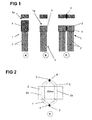
- the Fig. 1 shows a schematic representation of three essential steps in the manufacturing process of a winding for a stator of an electric machine. At the far left and designated A, a stranded wire 1 is shown, the end 1 a is provided with a sleeve 4. In order to reliably prevent the formation of domains in cross section, which run mostly in the interior of the stranded wire 1, usually the individual wires 7 are twisted multiple times.
- the stranded wire 1 is penetrated during operation by various magnetic fields (stray fields, rotor fields, ). Since it is electrically short-circuited at both ends 1a by the electrical connection between the individual wires 7 of the stranded wires 1, which is accomplished at least in part via the sleeve 4, form between the individual wires 7 one and the same stranded wire 1 one or more conductor loops. In these conductor loops, a voltage is induced by the existing field.
- the parasitic currents in the conductor loop, which follow from the induced voltages should be as low as possible, which can be achieved via a suitable type of twisting and stranding.
- the individual wires 7 of the shaped strands which consist for example of copper, aluminum or similar electrically conductive materials, each surrounded by an insulating lacquer layer.
- the twisting and the deformation into the desired shape causes the individual wires 7 are pressed together with their paint layers.
- the lacquer layers of adjacent individual wires 7 stick together, for example by adding an additional material (for example a resin), or ensure adhesion, which gives the shaped strands 1 as a whole stability.
- the twisted individual wires 7 can be soaked with an adhesive, such as resin.
- the use of baked enamel wires may make sense, which type of wires baked together by heat. Also by this measure improved stability can be achieved.
- these connecting components can be applied to the rollers from the outside.
- these connecting components can also already be present on the wire, which represents the individual wires 7 of the stranded wire 1, as is the case with back-lacquer-coated wires.
- the materials connecting the individual wires could also be present within the strand. Similar to fiber composites, for example, one or more filaments of a polymer could be drilled in, which treats on later heating and cakes the strand packet.
- the mechanical connection takes place together with the electrical contact on at least one of the ends 1a of the shaped strands 1, additionally such a mechanical connection can be provided over the covering or insulation of the individual wires 7.
- the shaped strands 1 are also brought to the desired length, preferably cut to size.
- This also has the advantage that the compacted during the compaction of the individual wires 7 of the stranded wire 1 or during compression of the sleeve 4 in the direction of the outer end 1a of the stranded wire 1 ausquetsche adhesive or similar contaminants are cut away.
- the shortened sleeve 4 of in Fig.1 in the middle - letter B - illustrated stranded wire 1 is already clean or easy to clean, so that a secure connection with another stranded wire 1 can be produced.
- An example of an advantageous joining method is a soldering process.
- two adjacent surfaces of two sleeves 4 different shaped strands 1 are connected by a braze, which may already be on a sleeve side before.
- the braze can also be done after Assembling the ends 1a of the form strands 1 are added.
- the heating of the solder can be accomplished by a variety of processes: heating by a flame, inductive heating, etc.
- a connection of the sleeves 4 by welding, in particular by resistance welding, is possible. Due to the good lateral accessibility in the stator 2, the two sleeves 4 can be pressed together well, positioned and then connected.
- the stranded wire 1 is contacted after cutting at its two ends 1 a.
- the contacting is preferably carried out over a certain longitudinal section at the respective end 1a of the stranded wire 1 and preferably by a welding operation, preferably by resistance welding.
- a welding operation preferably by resistance welding.
- the connection process preferably comprises all the individual wires at the respective end 1a of the shaped strands 1, in order to ensure optimum stability and electrical connection.
- the individual wires of the stranded wire 1 can be contacted before cutting to preferably both ends 1a, ie both electrically conductive contacted as well as mechanically connected, are.
- the shaped strands 1 in one cut to length in the following process step.
- the clearly defined geometry of the ends 1a of the stranded wire 1 significantly simplifies the automation in contrast to conventional shaped strands, the geometry of which can be changed by twisting or displacement of the individual wires.
- the contacting of the inner and outer stranded wire 1 within each of the stator slots 2a and the irregular interconnections is also simplified, since the individual wires are already electrically connected by the respectively selected connection method.
- At least one of the contacted - and thus also mechanically connected - ends 1a of the shaped strands 1 are also compacted, i. it is the cross-section of this end 1 a or at least reduced to a circumferential position of the diameter or at least the width at a point of this end 1 a.
- both ends 1a of the stranded wire 1 can be achieved that the outer geometry of the ends 1 a as well as those of the central longitudinal portion 1 b of the shaped strands 1 is preferably smaller at each point of the circumference than the groove geometry.
- the novel shaped strands 1 with their contacted and compacted ends 1a can be inserted automatically into the stator slots 2a.
- a radial insertion into the stator 2 is not possible with parallel grooves 2a with groove base with superimposed (and not adjacent) form rods because of the groove foot.
- this is also not possible because in internal running machines, the trapezium tapers inwards.
- the shaping strands 1 can also be inserted radially.
- the enveloping cross section of the shaped strand 1 in at least one of the longitudinal sections of interconnected individual wires is smaller than the cross section in the subsequent longitudinal section.
- the cross-sectional shape of the stranded wire 1 corresponds to the trapezoidal shape of the stator 2a, at least in the central longitudinal section between the electric and mechanically connected and also compacted to a smaller cross-section ends 1 a.
- the smaller cross section is provided at least at that end of the stranded wire 1 on the axially inserted into the stator 2 end of the stranded wire 1.
- the form wires 1 are not damaged during insertion and even adjacent Form strands 1 or the stator are not damaged. Both damage to the insulation of the individual wires and / or the slot insulation can be prevented, regardless of whether the slot insulation is already in the groove 2a or is on the stranded wire 1 at least before insertion. Likewise, damage to the stator 2, such as scratching of the sheets, can be prevented, whereby the efficiency of the machine worsening shorts can be prevented.
- Fig. 2 schematically shows a stator with two shaped strands 1, the connection via as in Fig. 1 on the far right (letter C) are mechanically and electrically connected.
- the shaped strands 1 are bent towards each other and then over the sleeves 4 connected. The fact that a flat connection between the two sleeves 4 is made, the angle between the two sleeves is arbitrary. Thus, a reverse bend behind the longitudinal section of the sleeve 4 of the stranded lines 1 can be avoided, resulting in the advantage of a shorter winding head, as in Fig. 2 can be seen.
- At least one end 1a can be tapered in a linear, conical, pyramidal or irregular taper, which naturally simplifies insertion into the stator 2. Likewise, this can offer 2 advantages for the downstream connection process in the winding head of the stator.
- the electrically conductive and also mechanically fixing connection of two pointed ends 1a of two different shaped strands 1 can be particularly advantageous at a geometrically defined end (eg pointed embodiment of the ends 1a, or also defined flat geometry or geometry in which a notch between the shaping strands 1) can be produced by a process in which current flows from an electrode E into the tapered ends 1a of the shaping wires 1 and thus by the fusion of the shaped strands 1 with or without additives an electrical and mechanical connection 3 small dimensions, substantially point or line, produces.
- the connection of two pointed ends 1 a two shaped strands 1 by a TIG welding process, possibly without additive are prepared.
- the shaped strands 1 are bent towards each other with their ends 4 a provided with sleeves 1 a and provided at the points of contact in the same way with an electrical and mechanical connection 3 small dimensions, substantially approximately point or line.
- connection of two converging shaped strands 1 with or without sleeves 4 to the stator 2 projecting ends 1 a by resistance welding or a similar method also linear over a larger longitudinal section of the ends 1 a or even be performed flat.
- the defined geometry of the ends 1a offers advantages over shaped strands of unconnected individual wires.
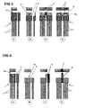
- the Fig. 3 shows a variant in which a tab 8 is inserted longitudinally in the sleeve 4.
- a first step shown on the left with the letter A, sleeve 4 and tab 8 are the same length.
- the individual wires 7 of the raw shaped strand 1 are also inserted into the sleeve 4.
- Sleeve 4, tab 8 and the individual wires 7 are pre-compacted together. It is, as already in connection with Fig. 1 explained, the single wire insulation heats and melts. By pressing during precompacting, the insulation exits from the front of the stranded wire 1.
- the tab 8 When subsequently shortening the stranded wire 1 and the sleeve 4, the tab 8 is excluded so that it finally protrudes beyond the end 1a of the stranded wire 1 and over the sleeve 4.
- the shortening can be done for example by milling or by a sheet metal cutting process.
- a tab 8 made of pure copper is used. After removing any remaining pollution, this tab 8 can be used for the subsequent connection process. In this case, about two tabs 8 different shaped strands 1 are welded together directly, as in Fig. 3 , Letter C, is shown.
- the tabs 8 can be in the connection region 3 with their flat surfaces or with their side edges together.
- a connection piece 8a of an electrically conductive material for example, copper bar
- the connection of the shaped strands 1 are accomplished.
- Such a compound is in Fig. 3 on the far right, at the letter C '. Due to the good accessibility from above in the stator 2, all these welding processes can be carried out from above.
- the tab 8 can possibly be welded to the already shortened sleeve 4.
- the two flags thus formed can then be welded together from above, as in Fig. 4 again on the far right, at the letter D, represented
- a sleeve 4 which is designed thicker on one side.
- a step is cut into the sleeve 4, so that the thicker side protrudes as a tab 8.
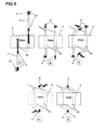
- FIG. 5 An advantageous embodiment for producing the winding of a stator using shaped wires 1 with tabs 8 on the sleeves 4 is in the sequence of steps of Fig. 5 shown.
- This method can be applied to all shaped strands 1 with tabs 8.
- Formed wires 1 are preferably used, in which the tabs 8 are provided at both ends, but asymmetrical.
- the tab 8 at the end 1a of the stranded wire 1, which end is inserted through the stator 2 is elongated and the sleeve designed to be outstanding in the axial direction, so that it does not exceed the available cross-section of the stator 2a.
- the tab 8 at the other end 1a of the stranded wire 1, which is not plugged through the stator 2 is in principle freely designable in its geometry.
- the shaped strands 1 can also be inserted from different positions in the groove from different sides (illustrations of the letters A and B of Fig. 5 ).
- the tabs are 8 after bending (letter C) directly above each other (as in the figure at the letter D of Fig. 5 ). This can save a second bending process.
- connection methods already explained above be applied to the adjacent tabs 8 mechanically and electrically to the state as in letter E of Fig. 5 shown to connect. Again, the advantage of a shorter winding head can be achieved again.
Landscapes
- Engineering & Computer Science (AREA)
- Power Engineering (AREA)
- Manufacturing & Machinery (AREA)
- Manufacture Of Motors, Generators (AREA)
- Windings For Motors And Generators (AREA)
Priority Applications (1)
| Application Number | Priority Date | Filing Date | Title |
|---|---|---|---|
| EP15152755.3A EP3051669B1 (fr) | 2015-01-27 | 2015-01-27 | Bobine pour un stator, machine électrique, et procédé de fabrication de la bobine pour un stator |
Applications Claiming Priority (1)
| Application Number | Priority Date | Filing Date | Title |
|---|---|---|---|
| EP15152755.3A EP3051669B1 (fr) | 2015-01-27 | 2015-01-27 | Bobine pour un stator, machine électrique, et procédé de fabrication de la bobine pour un stator |
Publications (2)
| Publication Number | Publication Date |
|---|---|
| EP3051669A1 true EP3051669A1 (fr) | 2016-08-03 |
| EP3051669B1 EP3051669B1 (fr) | 2018-08-22 |
Family
ID=52432684
Family Applications (1)
| Application Number | Title | Priority Date | Filing Date |
|---|---|---|---|
| EP15152755.3A Active EP3051669B1 (fr) | 2015-01-27 | 2015-01-27 | Bobine pour un stator, machine électrique, et procédé de fabrication de la bobine pour un stator |
Country Status (1)
| Country | Link |
|---|---|
| EP (1) | EP3051669B1 (fr) |
Cited By (7)
| Publication number | Priority date | Publication date | Assignee | Title |
|---|---|---|---|---|
| WO2019040956A1 (fr) * | 2017-08-28 | 2019-03-07 | Miba Aktiengesellschaft | Composant de stator pour machine électrique |
| WO2019228846A1 (fr) | 2018-05-28 | 2019-12-05 | Thyssenkrupp Ag | Procédé pour la fabrication d'un toron profilé, procédé pour la fabrication d'un moteur électrique ainsi qu'utilisation d'un toron profilé |
| WO2019228923A1 (fr) | 2018-05-28 | 2019-12-05 | Thyssenkrupp Ag | Procédé pour la fabrication d'un toron profilé, procédé pour la fabrication d'un moteur électrique ainsi qu'utilisation d'un toron profilé |
| WO2020089322A1 (fr) * | 2018-10-31 | 2020-05-07 | Thyssenkrupp Ag | Toron profilé, stator ou rotor d'une machine électrique, et machine électrique |
| CN112425052A (zh) * | 2018-07-17 | 2021-02-26 | 汉拿电驱动股份有限公司 | 用于压制绞合线的热处理的方法以及用于制造电动机的方法和用于制造机动车辆的方法 |
| DE102020207515A1 (de) | 2020-06-17 | 2021-12-23 | Volkswagen Aktiengesellschaft | Verfahren und Verbindungselement zum Verbinden von elektrischen Leitern einer elektrischen Maschine |
| EP3934067A1 (fr) * | 2020-06-30 | 2022-01-05 | Siemens Mobility GmbH | Système de bobinage pour machine électrique |
Families Citing this family (6)
| Publication number | Priority date | Publication date | Assignee | Title |
|---|---|---|---|---|
| WO2023218047A1 (fr) | 2022-05-13 | 2023-11-16 | Hofer Powertrain Innovation Gmbh | Procédé de fabrication d'un segment conducteur pour un enroulement et de fabrication d'un stator pour une machine électrique ayant une conception d'enroulement hybride |
| DE102022112129A1 (de) | 2022-05-13 | 2023-11-16 | Hofer Powertrain Innovation Gmbh | Stator für eine elektrische Maschine mit einem Formlitzenwickelkopf sowie eine entsprechende elektrische Maschine und ein Herstellungsverfahren für einen Stator |
| DE102022005023A1 (de) | 2022-05-13 | 2023-11-30 | Hofer Powertrain Innovation Gmbh | Verfahren zur Herstellung eines Leitungssegments für eine Wicklung sowie eines Stators für eine Elektromaschine mit hybridem Wicklungsdesign |
| WO2023218044A2 (fr) | 2022-05-13 | 2023-11-16 | Hofer Powertrain Innovation Gmbh | Stator pour une machine électrique comprenant une tête d'enroulement de toron profilé, machine électrique correspondante et procédé de production d'un stator |
| DE102022112127A1 (de) | 2022-05-13 | 2023-11-16 | Hofer Powertrain Innovation Gmbh | Stator für eine Elektromaschine mit hybridem Wicklungsdesign |
| DE102022112126A1 (de) | 2022-05-13 | 2023-11-16 | Hofer Powertrain Innovation Gmbh | Leitungssegment für eine Wicklung einer elektrischen Maschine sowie ein Herstellungsverfahren für ein Leitungssegment |
Citations (1)
| Publication number | Priority date | Publication date | Assignee | Title |
|---|---|---|---|---|
| WO1999030405A1 (fr) * | 1997-11-25 | 1999-06-17 | Abb Ab | Enroulement haute tension |
Family Cites Families (2)
| Publication number | Priority date | Publication date | Assignee | Title |
|---|---|---|---|---|
| US4260924A (en) * | 1978-09-27 | 1981-04-07 | Westinghouse Electric Corp. | Conductor bar for dynamoelectric machines |
| DE19840125A1 (de) * | 1998-09-03 | 2000-03-09 | Abb Patent Gmbh | Verbindung von elektrischen Leitern und Verfahren zur Verbindung von elektrischen Leitern |
-
2015
- 2015-01-27 EP EP15152755.3A patent/EP3051669B1/fr active Active
Patent Citations (1)
| Publication number | Priority date | Publication date | Assignee | Title |
|---|---|---|---|---|
| WO1999030405A1 (fr) * | 1997-11-25 | 1999-06-17 | Abb Ab | Enroulement haute tension |
Cited By (9)
| Publication number | Priority date | Publication date | Assignee | Title |
|---|---|---|---|---|
| WO2019040956A1 (fr) * | 2017-08-28 | 2019-03-07 | Miba Aktiengesellschaft | Composant de stator pour machine électrique |
| WO2019228846A1 (fr) | 2018-05-28 | 2019-12-05 | Thyssenkrupp Ag | Procédé pour la fabrication d'un toron profilé, procédé pour la fabrication d'un moteur électrique ainsi qu'utilisation d'un toron profilé |
| WO2019228923A1 (fr) | 2018-05-28 | 2019-12-05 | Thyssenkrupp Ag | Procédé pour la fabrication d'un toron profilé, procédé pour la fabrication d'un moteur électrique ainsi qu'utilisation d'un toron profilé |
| CN112640273A (zh) * | 2018-05-28 | 2021-04-09 | 汉拿电驱动股份有限公司 | 用于制造压制绞合线的方法、用于制造电动马达的方法以及压制绞合线的应用 |
| CN112425052A (zh) * | 2018-07-17 | 2021-02-26 | 汉拿电驱动股份有限公司 | 用于压制绞合线的热处理的方法以及用于制造电动机的方法和用于制造机动车辆的方法 |
| WO2020089322A1 (fr) * | 2018-10-31 | 2020-05-07 | Thyssenkrupp Ag | Toron profilé, stator ou rotor d'une machine électrique, et machine électrique |
| CN112997382A (zh) * | 2018-10-31 | 2021-06-18 | 汉拿电驱动股份有限公司 | 压制绞合线、电机的定子或转子以及电机 |
| DE102020207515A1 (de) | 2020-06-17 | 2021-12-23 | Volkswagen Aktiengesellschaft | Verfahren und Verbindungselement zum Verbinden von elektrischen Leitern einer elektrischen Maschine |
| EP3934067A1 (fr) * | 2020-06-30 | 2022-01-05 | Siemens Mobility GmbH | Système de bobinage pour machine électrique |
Also Published As
| Publication number | Publication date |
|---|---|
| EP3051669B1 (fr) | 2018-08-22 |
Similar Documents
| Publication | Publication Date | Title |
|---|---|---|
| EP3051669B1 (fr) | Bobine pour un stator, machine électrique, et procédé de fabrication de la bobine pour un stator | |
| WO2015162586A2 (fr) | Toron profilé, son utilisation, ainsi que procédé de fabrication d'un stator destiné à une machine électrique | |
| EP2013961B1 (fr) | Procédé de fabrication d'un enroulement à cage d'écureuil pour le stator d'un moteur électrique | |
| EP3270489B1 (fr) | Bobine formée pour la fabrication d'un enroulement à entrefer autoportant, notamment enroulement oblique d'un petit moteur électrique | |
| DE102015225585A1 (de) | Wicklung für eine elektrische Maschine und Verfahren zu deren Herstellung | |
| EP3895282B1 (fr) | Stator, composant de raccordement et machine électrique | |
| WO2004088824A1 (fr) | Procede de fabrication d'enroulements et de circuits d'enroulements | |
| WO2019141722A1 (fr) | Stator pour une machine électrique et son procédé de fabrication | |
| DE102018218732A1 (de) | Formlitze, Stator oder Rotor einer elektrischen Maschine, sowie elektrische Maschine | |
| DE102006036607B4 (de) | Elektromagnetisches Schweißverfahren und Leitermodul | |
| DE102018208407A1 (de) | Verfahren zur Herstellung von Formlitze, Verfahren zur Herstellung eines Elektromotors, sowie Verwendung von Formlitze | |
| WO2018007060A1 (fr) | Stator d'une machine électrique | |
| DE102019133660A1 (de) | Rotierende elektrische Maschine und Verfahren zu deren Herstellung | |
| WO2022079136A1 (fr) | Stator pour une machine électrique, procédé de fabrication d'un stator, et machine électrique | |
| AT519980B1 (de) | Statorkomponente für eine elektrische Maschine | |
| DE102016119841B4 (de) | Verfahren zur Herstellung eines für eine elektrische Maschine vorgesehenen Stators, sowie Stator | |
| EP1544984B1 (fr) | Enroulement pour machines électriques et procédé pour son fabrication de pieces moulées | |
| DE102019210146B4 (de) | Verfahren zur Herstellung eines Stator eines Elektromotors | |
| DE10360476A1 (de) | Verfahren zur Verbindung von Motorleitungsdrähten, Verbindungsaufbau und Motor | |
| DE10059575A1 (de) | Elektrische Maschine und Stator für eine elektrische Maschine und Herstellungsverfahren dafür | |
| EP3631912A1 (fr) | Procédé de contact pour conducteurs isolés au vernis | |
| DE102014224393A1 (de) | Spule für eine elektrische Maschine zum Anordnen um einen ein elektrisches Feld führenden Kern und Verfahren zur Herstellung einer entsprechenden Spule | |
| WO2019115059A1 (fr) | Procédé de dénudage d'un conducteur électrique et stator d'une machine électrique | |
| WO2023242164A1 (fr) | Procédé de fabrication d'un composant générateur d'énergie d'une machine électrique tournante et machine électrique tournante | |
| DE102022112126A1 (de) | Leitungssegment für eine Wicklung einer elektrischen Maschine sowie ein Herstellungsverfahren für ein Leitungssegment |
Legal Events
| Date | Code | Title | Description |
|---|---|---|---|
| PUAI | Public reference made under article 153(3) epc to a published international application that has entered the european phase |
Free format text: ORIGINAL CODE: 0009012 |
|
| AK | Designated contracting states |
Kind code of ref document: A1 Designated state(s): AL AT BE BG CH CY CZ DE DK EE ES FI FR GB GR HR HU IE IS IT LI LT LU LV MC MK MT NL NO PL PT RO RS SE SI SK SM TR |
|
| AX | Request for extension of the european patent |
Extension state: BA ME |
|
| STAA | Information on the status of an ep patent application or granted ep patent |
Free format text: STATUS: REQUEST FOR EXAMINATION WAS MADE |
|
| 17P | Request for examination filed |
Effective date: 20170203 |
|
| RBV | Designated contracting states (corrected) |
Designated state(s): AL AT BE BG CH CY CZ DE DK EE ES FI FR GB GR HR HU IE IS IT LI LT LU LV MC MK MT NL NO PL PT RO RS SE SI SK SM TR |
|
| GRAP | Despatch of communication of intention to grant a patent |
Free format text: ORIGINAL CODE: EPIDOSNIGR1 |
|
| STAA | Information on the status of an ep patent application or granted ep patent |
Free format text: STATUS: GRANT OF PATENT IS INTENDED |
|
| INTG | Intention to grant announced |
Effective date: 20180319 |
|
| GRAS | Grant fee paid |
Free format text: ORIGINAL CODE: EPIDOSNIGR3 |
|
| GRAA | (expected) grant |
Free format text: ORIGINAL CODE: 0009210 |
|
| STAA | Information on the status of an ep patent application or granted ep patent |
Free format text: STATUS: THE PATENT HAS BEEN GRANTED |
|
| AK | Designated contracting states |
Kind code of ref document: B1 Designated state(s): AL AT BE BG CH CY CZ DE DK EE ES FI FR GB GR HR HU IE IS IT LI LT LU LV MC MK MT NL NO PL PT RO RS SE SI SK SM TR |
|
| REG | Reference to a national code |
Ref country code: GB Ref legal event code: FG4D Free format text: NOT ENGLISH |
|
| REG | Reference to a national code |
Ref country code: CH Ref legal event code: EP |
|
| REG | Reference to a national code |
Ref country code: AT Ref legal event code: REF Ref document number: 1033596 Country of ref document: AT Kind code of ref document: T Effective date: 20180915 |
|
| REG | Reference to a national code |
Ref country code: IE Ref legal event code: FG4D Free format text: LANGUAGE OF EP DOCUMENT: GERMAN |
|
| REG | Reference to a national code |
Ref country code: DE Ref legal event code: R096 Ref document number: 502015005522 Country of ref document: DE |
|
| REG | Reference to a national code |
Ref country code: NL Ref legal event code: MP Effective date: 20180822 |
|
| REG | Reference to a national code |
Ref country code: LT Ref legal event code: MG4D |
|
| PG25 | Lapsed in a contracting state [announced via postgrant information from national office to epo] |
Ref country code: NO Free format text: LAPSE BECAUSE OF FAILURE TO SUBMIT A TRANSLATION OF THE DESCRIPTION OR TO PAY THE FEE WITHIN THE PRESCRIBED TIME-LIMIT Effective date: 20181122 Ref country code: GR Free format text: LAPSE BECAUSE OF FAILURE TO SUBMIT A TRANSLATION OF THE DESCRIPTION OR TO PAY THE FEE WITHIN THE PRESCRIBED TIME-LIMIT Effective date: 20181123 Ref country code: RS Free format text: LAPSE BECAUSE OF FAILURE TO SUBMIT A TRANSLATION OF THE DESCRIPTION OR TO PAY THE FEE WITHIN THE PRESCRIBED TIME-LIMIT Effective date: 20180822 Ref country code: SE Free format text: LAPSE BECAUSE OF FAILURE TO SUBMIT A TRANSLATION OF THE DESCRIPTION OR TO PAY THE FEE WITHIN THE PRESCRIBED TIME-LIMIT Effective date: 20180822 Ref country code: FI Free format text: LAPSE BECAUSE OF FAILURE TO SUBMIT A TRANSLATION OF THE DESCRIPTION OR TO PAY THE FEE WITHIN THE PRESCRIBED TIME-LIMIT Effective date: 20180822 Ref country code: LT Free format text: LAPSE BECAUSE OF FAILURE TO SUBMIT A TRANSLATION OF THE DESCRIPTION OR TO PAY THE FEE WITHIN THE PRESCRIBED TIME-LIMIT Effective date: 20180822 Ref country code: IS Free format text: LAPSE BECAUSE OF FAILURE TO SUBMIT A TRANSLATION OF THE DESCRIPTION OR TO PAY THE FEE WITHIN THE PRESCRIBED TIME-LIMIT Effective date: 20181222 Ref country code: NL Free format text: LAPSE BECAUSE OF FAILURE TO SUBMIT A TRANSLATION OF THE DESCRIPTION OR TO PAY THE FEE WITHIN THE PRESCRIBED TIME-LIMIT Effective date: 20180822 Ref country code: BG Free format text: LAPSE BECAUSE OF FAILURE TO SUBMIT A TRANSLATION OF THE DESCRIPTION OR TO PAY THE FEE WITHIN THE PRESCRIBED TIME-LIMIT Effective date: 20181122 |
|
| PG25 | Lapsed in a contracting state [announced via postgrant information from national office to epo] |
Ref country code: AL Free format text: LAPSE BECAUSE OF FAILURE TO SUBMIT A TRANSLATION OF THE DESCRIPTION OR TO PAY THE FEE WITHIN THE PRESCRIBED TIME-LIMIT Effective date: 20180822 Ref country code: LV Free format text: LAPSE BECAUSE OF FAILURE TO SUBMIT A TRANSLATION OF THE DESCRIPTION OR TO PAY THE FEE WITHIN THE PRESCRIBED TIME-LIMIT Effective date: 20180822 Ref country code: HR Free format text: LAPSE BECAUSE OF FAILURE TO SUBMIT A TRANSLATION OF THE DESCRIPTION OR TO PAY THE FEE WITHIN THE PRESCRIBED TIME-LIMIT Effective date: 20180822 |
|
| PG25 | Lapsed in a contracting state [announced via postgrant information from national office to epo] |
Ref country code: EE Free format text: LAPSE BECAUSE OF FAILURE TO SUBMIT A TRANSLATION OF THE DESCRIPTION OR TO PAY THE FEE WITHIN THE PRESCRIBED TIME-LIMIT Effective date: 20180822 Ref country code: PL Free format text: LAPSE BECAUSE OF FAILURE TO SUBMIT A TRANSLATION OF THE DESCRIPTION OR TO PAY THE FEE WITHIN THE PRESCRIBED TIME-LIMIT Effective date: 20180822 Ref country code: ES Free format text: LAPSE BECAUSE OF FAILURE TO SUBMIT A TRANSLATION OF THE DESCRIPTION OR TO PAY THE FEE WITHIN THE PRESCRIBED TIME-LIMIT Effective date: 20180822 Ref country code: RO Free format text: LAPSE BECAUSE OF FAILURE TO SUBMIT A TRANSLATION OF THE DESCRIPTION OR TO PAY THE FEE WITHIN THE PRESCRIBED TIME-LIMIT Effective date: 20180822 Ref country code: CZ Free format text: LAPSE BECAUSE OF FAILURE TO SUBMIT A TRANSLATION OF THE DESCRIPTION OR TO PAY THE FEE WITHIN THE PRESCRIBED TIME-LIMIT Effective date: 20180822 Ref country code: IT Free format text: LAPSE BECAUSE OF FAILURE TO SUBMIT A TRANSLATION OF THE DESCRIPTION OR TO PAY THE FEE WITHIN THE PRESCRIBED TIME-LIMIT Effective date: 20180822 |
|
| REG | Reference to a national code |
Ref country code: DE Ref legal event code: R097 Ref document number: 502015005522 Country of ref document: DE |
|
| PG25 | Lapsed in a contracting state [announced via postgrant information from national office to epo] |
Ref country code: SK Free format text: LAPSE BECAUSE OF FAILURE TO SUBMIT A TRANSLATION OF THE DESCRIPTION OR TO PAY THE FEE WITHIN THE PRESCRIBED TIME-LIMIT Effective date: 20180822 Ref country code: SM Free format text: LAPSE BECAUSE OF FAILURE TO SUBMIT A TRANSLATION OF THE DESCRIPTION OR TO PAY THE FEE WITHIN THE PRESCRIBED TIME-LIMIT Effective date: 20180822 Ref country code: DK Free format text: LAPSE BECAUSE OF FAILURE TO SUBMIT A TRANSLATION OF THE DESCRIPTION OR TO PAY THE FEE WITHIN THE PRESCRIBED TIME-LIMIT Effective date: 20180822 |
|
| PLBE | No opposition filed within time limit |
Free format text: ORIGINAL CODE: 0009261 |
|
| STAA | Information on the status of an ep patent application or granted ep patent |
Free format text: STATUS: NO OPPOSITION FILED WITHIN TIME LIMIT |
|
| 26N | No opposition filed |
Effective date: 20190523 |
|
| PG25 | Lapsed in a contracting state [announced via postgrant information from national office to epo] |
Ref country code: MC Free format text: LAPSE BECAUSE OF FAILURE TO SUBMIT A TRANSLATION OF THE DESCRIPTION OR TO PAY THE FEE WITHIN THE PRESCRIBED TIME-LIMIT Effective date: 20180822 Ref country code: SI Free format text: LAPSE BECAUSE OF FAILURE TO SUBMIT A TRANSLATION OF THE DESCRIPTION OR TO PAY THE FEE WITHIN THE PRESCRIBED TIME-LIMIT Effective date: 20180822 |
|
| REG | Reference to a national code |
Ref country code: CH Ref legal event code: PL |
|
| PG25 | Lapsed in a contracting state [announced via postgrant information from national office to epo] |
Ref country code: LU Free format text: LAPSE BECAUSE OF NON-PAYMENT OF DUE FEES Effective date: 20190127 |
|
| REG | Reference to a national code |
Ref country code: BE Ref legal event code: MM Effective date: 20190131 |
|
| REG | Reference to a national code |
Ref country code: IE Ref legal event code: MM4A |
|
| PG25 | Lapsed in a contracting state [announced via postgrant information from national office to epo] |
Ref country code: BE Free format text: LAPSE BECAUSE OF NON-PAYMENT OF DUE FEES Effective date: 20190131 |
|
| PG25 | Lapsed in a contracting state [announced via postgrant information from national office to epo] |
Ref country code: LI Free format text: LAPSE BECAUSE OF NON-PAYMENT OF DUE FEES Effective date: 20190131 Ref country code: CH Free format text: LAPSE BECAUSE OF NON-PAYMENT OF DUE FEES Effective date: 20190131 |
|
| PG25 | Lapsed in a contracting state [announced via postgrant information from national office to epo] |
Ref country code: IE Free format text: LAPSE BECAUSE OF NON-PAYMENT OF DUE FEES Effective date: 20190127 |
|
| PG25 | Lapsed in a contracting state [announced via postgrant information from national office to epo] |
Ref country code: TR Free format text: LAPSE BECAUSE OF FAILURE TO SUBMIT A TRANSLATION OF THE DESCRIPTION OR TO PAY THE FEE WITHIN THE PRESCRIBED TIME-LIMIT Effective date: 20180822 |
|
| PG25 | Lapsed in a contracting state [announced via postgrant information from national office to epo] |
Ref country code: PT Free format text: LAPSE BECAUSE OF FAILURE TO SUBMIT A TRANSLATION OF THE DESCRIPTION OR TO PAY THE FEE WITHIN THE PRESCRIBED TIME-LIMIT Effective date: 20181222 Ref country code: MT Free format text: LAPSE BECAUSE OF FAILURE TO SUBMIT A TRANSLATION OF THE DESCRIPTION OR TO PAY THE FEE WITHIN THE PRESCRIBED TIME-LIMIT Effective date: 20180822 |
|
| REG | Reference to a national code |
Ref country code: AT Ref legal event code: MM01 Ref document number: 1033596 Country of ref document: AT Kind code of ref document: T Effective date: 20200127 |
|
| PG25 | Lapsed in a contracting state [announced via postgrant information from national office to epo] |
Ref country code: AT Free format text: LAPSE BECAUSE OF NON-PAYMENT OF DUE FEES Effective date: 20200127 Ref country code: CY Free format text: LAPSE BECAUSE OF FAILURE TO SUBMIT A TRANSLATION OF THE DESCRIPTION OR TO PAY THE FEE WITHIN THE PRESCRIBED TIME-LIMIT Effective date: 20180822 |
|
| PG25 | Lapsed in a contracting state [announced via postgrant information from national office to epo] |
Ref country code: HU Free format text: LAPSE BECAUSE OF FAILURE TO SUBMIT A TRANSLATION OF THE DESCRIPTION OR TO PAY THE FEE WITHIN THE PRESCRIBED TIME-LIMIT; INVALID AB INITIO Effective date: 20150127 |
|
| PG25 | Lapsed in a contracting state [announced via postgrant information from national office to epo] |
Ref country code: MK Free format text: LAPSE BECAUSE OF FAILURE TO SUBMIT A TRANSLATION OF THE DESCRIPTION OR TO PAY THE FEE WITHIN THE PRESCRIBED TIME-LIMIT Effective date: 20180822 |
|
| PGFP | Annual fee paid to national office [announced via postgrant information from national office to epo] |
Ref country code: FR Payment date: 20230123 Year of fee payment: 9 |
|
| REG | Reference to a national code |
Ref country code: DE Ref legal event code: R081 Ref document number: 502015005522 Country of ref document: DE Owner name: BRUSA TECHNOLOGY AG, CH Free format text: FORMER OWNER: BRUSA ELEKTRONIK AG, SENNWALD, CH |
|
| REG | Reference to a national code |
Ref country code: GB Ref legal event code: 732E Free format text: REGISTERED BETWEEN 20231102 AND 20231108 |
|
| PGFP | Annual fee paid to national office [announced via postgrant information from national office to epo] |
Ref country code: DE Payment date: 20240124 Year of fee payment: 10 Ref country code: GB Payment date: 20240124 Year of fee payment: 10 |