EP3051656B1 - System und verfahren zur soc-korrektur einer batterie - Google Patents
System und verfahren zur soc-korrektur einer batterie Download PDFInfo
- Publication number
- EP3051656B1 EP3051656B1 EP15837076.7A EP15837076A EP3051656B1 EP 3051656 B1 EP3051656 B1 EP 3051656B1 EP 15837076 A EP15837076 A EP 15837076A EP 3051656 B1 EP3051656 B1 EP 3051656B1
- Authority
- EP
- European Patent Office
- Prior art keywords
- battery
- soc
- range
- charging
- operation range
- Prior art date
- Legal status (The legal status is an assumption and is not a legal conclusion. Google has not performed a legal analysis and makes no representation as to the accuracy of the status listed.)
- Active
Links
Images


Classifications
-
- H02J7/865—
-
- H02J7/933—
-
- B—PERFORMING OPERATIONS; TRANSPORTING
- B60—VEHICLES IN GENERAL
- B60L—PROPULSION OF ELECTRICALLY-PROPELLED VEHICLES; SUPPLYING ELECTRIC POWER FOR AUXILIARY EQUIPMENT OF ELECTRICALLY-PROPELLED VEHICLES; ELECTRODYNAMIC BRAKE SYSTEMS FOR VEHICLES IN GENERAL; MAGNETIC SUSPENSION OR LEVITATION FOR VEHICLES; MONITORING OPERATING VARIABLES OF ELECTRICALLY-PROPELLED VEHICLES; ELECTRIC SAFETY DEVICES FOR ELECTRICALLY-PROPELLED VEHICLES
- B60L3/00—Electric devices on electrically-propelled vehicles for safety purposes; Monitoring operating variables, e.g. speed, deceleration or energy consumption
- B60L3/0023—Detecting, eliminating, remedying or compensating for drive train abnormalities, e.g. failures within the drive train
- B60L3/0046—Detecting, eliminating, remedying or compensating for drive train abnormalities, e.g. failures within the drive train relating to electric energy storage systems, e.g. batteries or capacitors
-
- B—PERFORMING OPERATIONS; TRANSPORTING
- B60—VEHICLES IN GENERAL
- B60L—PROPULSION OF ELECTRICALLY-PROPELLED VEHICLES; SUPPLYING ELECTRIC POWER FOR AUXILIARY EQUIPMENT OF ELECTRICALLY-PROPELLED VEHICLES; ELECTRODYNAMIC BRAKE SYSTEMS FOR VEHICLES IN GENERAL; MAGNETIC SUSPENSION OR LEVITATION FOR VEHICLES; MONITORING OPERATING VARIABLES OF ELECTRICALLY-PROPELLED VEHICLES; ELECTRIC SAFETY DEVICES FOR ELECTRICALLY-PROPELLED VEHICLES
- B60L58/00—Methods or circuit arrangements for monitoring or controlling batteries or fuel cells, specially adapted for electric vehicles
- B60L58/10—Methods or circuit arrangements for monitoring or controlling batteries or fuel cells, specially adapted for electric vehicles for monitoring or controlling batteries
- B60L58/12—Methods or circuit arrangements for monitoring or controlling batteries or fuel cells, specially adapted for electric vehicles for monitoring or controlling batteries responding to state of charge [SoC]
- B60L58/13—Maintaining the SoC within a determined range
-
- G—PHYSICS
- G01—MEASURING; TESTING
- G01R—MEASURING ELECTRIC VARIABLES; MEASURING MAGNETIC VARIABLES
- G01R31/00—Arrangements for testing electric properties; Arrangements for locating electric faults; Arrangements for electrical testing characterised by what is being tested not provided for elsewhere
- G01R31/36—Arrangements for testing, measuring or monitoring the electrical condition of accumulators or electric batteries, e.g. capacity or state of charge [SoC]
- G01R31/382—Arrangements for monitoring battery or accumulator variables, e.g. SoC
-
- H—ELECTRICITY
- H01—ELECTRIC ELEMENTS
- H01M—PROCESSES OR MEANS, e.g. BATTERIES, FOR THE DIRECT CONVERSION OF CHEMICAL ENERGY INTO ELECTRICAL ENERGY
- H01M10/00—Secondary cells; Manufacture thereof
- H01M10/42—Methods or arrangements for servicing or maintenance of secondary cells or secondary half-cells
- H01M10/44—Methods for charging or discharging
- H01M10/446—Initial charging measures
-
- H—ELECTRICITY
- H01—ELECTRIC ELEMENTS
- H01M—PROCESSES OR MEANS, e.g. BATTERIES, FOR THE DIRECT CONVERSION OF CHEMICAL ENERGY INTO ELECTRICAL ENERGY
- H01M10/00—Secondary cells; Manufacture thereof
- H01M10/42—Methods or arrangements for servicing or maintenance of secondary cells or secondary half-cells
- H01M10/48—Accumulators combined with arrangements for measuring, testing or indicating the condition of cells, e.g. the level or density of the electrolyte
-
- H—ELECTRICITY
- H02—GENERATION; CONVERSION OR DISTRIBUTION OF ELECTRIC POWER
- H02J—CIRCUIT ARRANGEMENTS OR SYSTEMS FOR SUPPLYING OR DISTRIBUTING ELECTRIC POWER; SYSTEMS FOR STORING ELECTRIC ENERGY
- H02J3/00—Circuit arrangements for AC mains or AC distribution networks
- H02J3/28—Arrangements for balancing of the load in a network by storage of energy
- H02J3/32—Arrangements for balancing of the load in a network by storage of energy using batteries with converting means
-
- H—ELECTRICITY
- H02—GENERATION; CONVERSION OR DISTRIBUTION OF ELECTRIC POWER
- H02J—CIRCUIT ARRANGEMENTS OR SYSTEMS FOR SUPPLYING OR DISTRIBUTING ELECTRIC POWER; SYSTEMS FOR STORING ELECTRIC ENERGY
- H02J7/00—Circuit arrangements for charging or depolarising batteries or for supplying loads from batteries
-
- H02J7/82—
-
- H02J7/875—
-
- H—ELECTRICITY
- H01—ELECTRIC ELEMENTS
- H01M—PROCESSES OR MEANS, e.g. BATTERIES, FOR THE DIRECT CONVERSION OF CHEMICAL ENERGY INTO ELECTRICAL ENERGY
- H01M10/00—Secondary cells; Manufacture thereof
- H01M10/05—Accumulators with non-aqueous electrolyte
- H01M10/052—Li-accumulators
- H01M10/0525—Rocking-chair batteries, i.e. batteries with lithium insertion or intercalation in both electrodes; Lithium-ion batteries
-
- H—ELECTRICITY
- H01—ELECTRIC ELEMENTS
- H01M—PROCESSES OR MEANS, e.g. BATTERIES, FOR THE DIRECT CONVERSION OF CHEMICAL ENERGY INTO ELECTRICAL ENERGY
- H01M2220/00—Batteries for particular applications
- H01M2220/20—Batteries in motive systems, e.g. vehicle, ship, plane
-
- H02J2105/37—
-
- Y—GENERAL TAGGING OF NEW TECHNOLOGICAL DEVELOPMENTS; GENERAL TAGGING OF CROSS-SECTIONAL TECHNOLOGIES SPANNING OVER SEVERAL SECTIONS OF THE IPC; TECHNICAL SUBJECTS COVERED BY FORMER USPC CROSS-REFERENCE ART COLLECTIONS [XRACs] AND DIGESTS
- Y02—TECHNOLOGIES OR APPLICATIONS FOR MITIGATION OR ADAPTATION AGAINST CLIMATE CHANGE
- Y02E—REDUCTION OF GREENHOUSE GAS [GHG] EMISSIONS, RELATED TO ENERGY GENERATION, TRANSMISSION OR DISTRIBUTION
- Y02E60/00—Enabling technologies; Technologies with a potential or indirect contribution to GHG emissions mitigation
- Y02E60/10—Energy storage using batteries
-
- Y—GENERAL TAGGING OF NEW TECHNOLOGICAL DEVELOPMENTS; GENERAL TAGGING OF CROSS-SECTIONAL TECHNOLOGIES SPANNING OVER SEVERAL SECTIONS OF THE IPC; TECHNICAL SUBJECTS COVERED BY FORMER USPC CROSS-REFERENCE ART COLLECTIONS [XRACs] AND DIGESTS
- Y02—TECHNOLOGIES OR APPLICATIONS FOR MITIGATION OR ADAPTATION AGAINST CLIMATE CHANGE
- Y02T—CLIMATE CHANGE MITIGATION TECHNOLOGIES RELATED TO TRANSPORTATION
- Y02T10/00—Road transport of goods or passengers
- Y02T10/60—Other road transportation technologies with climate change mitigation effect
- Y02T10/70—Energy storage systems for electromobility, e.g. batteries
Definitions
- the present invention relates to a system and method for correcting a state-of-charging (SOC) of a battery, and more particularly, to a system and method for maintaining an SOC value to a predetermined range while a battery is charged and discharged.
- SOC state-of-charging
- secondary batteries include nickel-cadmium batteries, nickel-hydrogen batteries, lithium ion batteries, and lithium ion polymer batteries.
- Such secondary batteries are classified into lithium based batteries and nickel-hydrogen based batteries.
- Lithium-based batteries are mainly used for small products such as digital cameras, P-DVDs, MP3Ps, cellular phones, PDAs, portable game devices, power tools, and E-bikes, and nickel hydrogen-based batteries are mainly applied to and used for large products such as electric vehicles or hybrid electric vehicles, which need high output.
- a motor To drive electric vehicles or hybrid electric vehicles, a motor has to be driven, which requires high output. Also, in case of the power storage devices for supplying power to buildings or certain areas, a large amount of power that is enough to satisfy power demands has to be supplied. As described above, to provide power having high output or large capacity, a plurality of batteries, each of which is composed of a unit cell assembly, are connected in series or parallel to each other to supply desired output or power.
- the difference in charging capacity may cause the overcharging or overdischarging of some of the unit cells.
- power may not be stably supplied to a load (e.g., an electric motor, a power grid, and the like).
- US 2013/113433 discloses classifying the state of the battery into a plurality of zones and controlling the charge and discharge of the battery correspondingly depending on to which region the current state of the battery corresponds.
- US 2009/250277 discloses the technique of equally charging the energy storage device in the hybrid electric automobile. US 2009/250277 teaches shifting the location of the battery power request transfer function having a power-SOC profile to maintain the SOC of the battery used in the hybrid automobile to a high level.
- EP 2055587 discloses monitoring the state-of-charge of the energy storage device and controlling the charge and discharge of the energy charging device based on the charge state.
- DE 102012208461 discloses partitioning the SOC of the battery into seven (7) regions by six (6) threshold values and controlling the charge of the battery depending on to which region the SOC of the battery corresponds.
- HUI LIU ET AL Decentralized Vehicle-to-Grid Control for Primary Frequency Regulation Considering Charging Demands
- V2G Vehicle-to-Grid
- EP 2145808 discloses calculating the SOC of the battery and controlling the charge and discharge of the battery based on the calculated SOC and the temperature of the battery.
- DE 10 2011 055232 A describes a method for providing control power for a power network, in which at least one energy store connected to the power network supplies energy to the power network as a function of a frequency deviation from a target frequency of the power network and/or absorbs energy from the power network.
- a deadband around the target frequency is specified, wherein the frequency deviation from the network frequency is measured with a higher accuracy than the width of the deadband, and a bandwidth is selected within the deadband as a function of a charging state of the energy store, wherein control power is provided outside the bandwidth.
- the document also describes a device for carrying out such a method, in which the device comprises at least one energy store and a control for controlling or regulating the control power of the energy store, wherein the energy store is connected to a power network such that energy can be supplied to the power network and be drawn from the power network by the device.
- An object of the present invention is to provide a system and method for correcting a battery SOC, which is capable of more efficiently correcting a battery SOC value to a predetermined range by adjusting a dead band in charging/discharging directions or adjusting charging/discharging power while charging/discharging a battery.
- a system for maintaining a state-of-charging (SOC) of a battery to be charged through power supplied from a power producing device of a battery energy storage system(BESS), within a predetermined range including: an SOC measuring unit configured to measure an SOC value of the battery; a storage unit configured to store preset operation ranges to determine whether charging/discharging of the battery is compensated, wherein values of the operation ranges are changed according to a state of the battery or surrounding environment; a determining unit configured to determine an operation range corresponding to the SOC value of the battery among the preset operation ranges, the determined operation range being a range on which a dead band in charging/discharging directions is based, a frequency correction signal range corresponding to a range of the dead band in charging/discharging directions being used to adjust an amount of a power signal applied to the battery; and an SOC correcting unit configured to adjust the dead band in charging/discharging directions to thereby adjust the frequency correction signal range according
- a method for maintaining a state-of-charging (SOC) of a battery to be charged through power supplied from a power producing device of a battery energy storage system (BESS), within a predetermined range including: measuring an SOC value of the battery; comparing the SOC value to preset operation ranges to determine an operation range corresponding to the SOC value, the determined operation range being a range on which a dead band in charging/discharging directions is based, a frequency correction signal range corresponding to a range of the dead band in charging/discharging directions being used to adjust an amount of a power signal applied to the battery, wherein values of the operation ranges are changed according to a state of the battery or surrounding environment; and adjusting the dead band in charging/discharging directions to thereby adjust the frequency correction signal range according to conditions corresponding to the operation range which corresponds to the SOC value to maintain the SOC value of the battery within the predetermined range.
- SOC state-of-charging
- the SOC correction may be performed by adjusting the dead band section in the charging/discharging directions or adjusting the charging/discharging power while charging/discharging the battery to maintain the SOC value of the battery within a predetermined range.
- the probability that the SOC value of the battery reaches about 100% or about 0% may be reduced, and the battery may be reduced in capacity when the battery is designed.
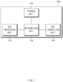
- FIG. 1 is a block diagram of a system for correcting a state-of-charging (SOC) of a battery according to an embodiment of the present invention.
- SOC state-of-charging
- a system 100 for correcting an SOC of a battery includes an SOC measuring unit 110, a storage unit 120, a determining unit 130, and an SOC correcting unit 140.
- the SOC measuring unit 110 measures an SOC value of the battery which is charged through power supplied from a power producing device of a battery energy storage system (BESS).
- BESS battery energy storage system
- the SOC measuring unit 110 may measure the SOC value of the battery at every preset unit time.
- the SOC value of the battery which is measured in the SOC measuring unit 110, is stored in the storage unit 120.
- a plurality of operation ranges corresponding to SOC values of the battery are stored in the storage unit 120.
- the plurality of operation ranges may be previously set to determine whether the charging/discharging of the battery is compensated.
- the operation range corresponding to the SOC value of the battery may be set to an operation range that are adequate for a lifecycle of the BESS.
- the operation ranges may be set to operation ranges for a reference value.
- an operation range is about 70% to about 100% of the SOC value of the battery, which is measured in the SOC measuring unit 110
- the operation range may be defined as a first operation range.
- the operation range may be defined as a second operation range, and if an operation range is about 0% to about 30% of the SOC value, the operation range may be defined as a third operation range.
- the second operation range may be determined as a normal range.
- the value of each of the operation ranges is set as described above.
- the values of the operation ranges are changed according to a state of the battery or surrounding environments.
- the determining unit 130 may compare the measured SOC value of the battery to the plurality of operation ranges stored in the storage unit 120 to determine an operation range corresponding to the measured SOC value of the battery among the plurality of operation ranges.
- the SOC correcting unit 140 stores correction values corresponding to the plurality of operation ranges.
- the correction values may be set to correction values different from each other according to the operation ranges.
- the first correction value corresponding to the first operation range may include conditions for increasing a dead band in a charging direction or decreasing the dead band in a discharging direction.
- the second correction value corresponding to the second operation range may include conditions for increasing the dead band in the charging/discharging directions or maintaining the present state
- the third correction value corresponding to the third operation range may include conditions for decreasing the dead band in the charging direction or increasing the dead band in the discharging direction.
- the SOC correcting unit 140 adjusts the dead band section according to the result determined in the determining unit 130 to correct the SOC value of the battery.
- the SOC correcting unit 140 increases the dead band in the charging direction or decreases the dead band in the discharging direction. Since the second operation range corresponds to the normal range, when it is determined that the measured SOC value of the battery corresponds to the second operation range, the present state is maintained. Here, even through the measured SOC value of the battery corresponds to the normal range, the dead band may be increased in the charging direction in consideration of efficiency of the battery.
- the dead band is decreased in the charging direction or increased in the discharging direction.
- the dead band section in the charging/discharging directions may be adjusted to correct the SOC value of the battery while charging/discharging the battery, thereby maintaining the SOC value within a predetermined range.
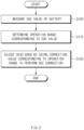
- FIG. 2 is a flowchart of a method for correcting the SOC of the battery according to an embodiment of the present invention.
- the SOC measuring unit 110 measures an SOC value of a battery which is charged through power supplied from the power producing device of the BESS (S100).
- the SOC value of the battery may be measured at every preset unit time.
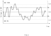
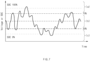
- FIG. 3 is a graph of SOC values of the battery, which are measured at every unit time. Referring to FIG. 3 , it is seen that an SOC value of the battery is frequently changed in a range of about 0% to about 100%.
- the determining unit (130) compares the measured SOC value of the battery to the plurality of operation ranges stored in the storage unit (see reference numeral 120 of FIG. 1 ) to determine an operation range corresponding to the measured SOC value among the plurality of operation ranges (S110).
- the plurality of operation ranges corresponding to the SOC values of the battery are stored in the storage unit 120.
- the plurality of operation ranges may be previously set to determine whether the charging/discharging of the battery is compensated.
- an x-axis in the graph may denote a time
- a y-axis in the graph may denote an SOC value of the battery.
- the SOC value of the battery may be partitively set to ranges of about 70% to about 100% (a first operation range: a), about 30% to about 70% (a second operation range: b), and about 0% to about 30% (a third operation range: c).
- the first operation state a is defined as an overcharged state
- the second operation range b is defined as a normal range
- the third operation range c is defined as an overcharged state.
- the value of each of the operation ranges is set as described above.
- the values of the operation ranges may be changed in consideration of capacity, charging efficiency, discharging resistance, and the like of the battery.
- the SOC correcting unit 140 performs SOC correction by using a correction value corresponding to the operation range which corresponds to the measured SOC value (S120).
- the SOC correction may adjust the dead band section in the charging/discharging directions according to the result determined in the operation S110.
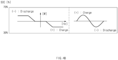
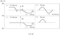
- the SOC correction value will be described with reference to the graphs of FIG. 4A to 4C .
- FIG. 4A illustrates a case in which the SOC value of the battery, which is measured in the SOC measuring unit corresponds to the first operation range a of about 70% to about 100%.
- the dead band is increased in the charging direction or decreased in the discharging direction.
- a range of the dead band in the charging direction is expanded to reduce a frequency correction signal range corresponding to the range of the dead band. Also, the number of power signal applied to the battery is decreased. Also, probability that the SOC value of the battery reaches about 100% is reduced.
- the range of the dead band in the discharging direction is decreased, and the frequency correction signal range corresponding to the range of the dead band is increased. Also, the number of power signal applied to the battery is increased. Also, probability that the SOC value of the battery reaches about 100% is reduced.
- the range of the dead band is decreased, and the frequency correction signal range corresponding to the range of the dead band is increased. Also, the number of power signal applied to the battery is increased, and probability that the SOC value of the battery reaches about 0% is reduced.
- the SOC value of the battery may be measured, and the operation range corresponding to the measured SOC value may be determined. Then, the dead band section may be adjusted by using the correction value corresponding to the operation range to maintain the SOC value within a predetermined range.
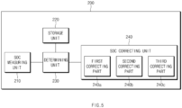
- FIG. 5 is a block diagram of a system 200 for correcting an SOC of a battery according to another embodiment of the present invention.
- a system 200 for correcting an SOC of a battery includes an SOC measuring unit 210, a storage unit 220, a determining unit 230, and an SOC correcting unit 240.
- the SOC measuring unit 210 measures an SOC value of the battery which is charged through power supplied from a power producing device of a battery energy storage system (BESS).
- BESS battery energy storage system
- the SOC value of the battery may be measured at every preset unit time.
- the SOC value of the battery which is measured in the SOC measuring unit 210, is stored in the storage unit 220.
- a plurality of operation ranges corresponding to SOC values of the battery are stored in the storage unit 220.
- the plurality of operation ranges may be previously set to determine whether the charging/discharging of the battery is compensated.
- the operation ranges corresponding to the SOC value of the battery may be set to operation ranges that are adequate for a lifecycle of the BESS.
- the operation ranges may be set to operation ranges for a reference value.
- an operation range is about 70% to about 100% of the SOC value of the battery, which is measured in the SOC measuring unit 210, the operation range may be set to a first operation range.
- the operation range may be set to a second operation range, and if an operation range is about 0% to about 30% of the SOC value, the operation range may be set to a third operation range.
- the second operation range may be determined as a normal range.
- the value of each of the operation ranges is set as described above.
- the values of the operation ranges are changed according to a state of the battery or surrounding environments.
- the determining unit 230 determines an operation range corresponding to the measured SOC value of the battery among the plurality of operation ranges.
- the SOC correcting unit 240 stores correction values corresponding to the plurality of operation ranges, respectively.
- the SOC correcting unit 240 includes a first correcting part 240a, a second correcting part 240b, and a third correcting part 240c.
- the correcting parts have correction values obtained by using charging/discharging power adjusting manners different from each other, respectively.
- the first correcting part 240a includes conditions for increasing or decreasing charging/discharging power in an exponential form.
- the second correcting part 240b includes conditions for increasing or decreasing the charging/discharging power in a stepped form.
- a third correcting part 240c includes conditions for increasing or decreasing the charging/discharging power at a predetermined ratio.
- the SOC correcting unit 240 adjusts the charging/discharging power according to the result determined in the determining unit 230 to correct the SOC value of the battery.
- one correcting part of the SOC correcting unit 240 is selected to perform the SOC correction by using the correction value of the selected correcting part, which corresponds to the first operation range.
- the charging power is decreased, or the discharging power is increased.
- the charging/discharging power may be increased or decreased in the exponential or stepped form or at the predetermined ratio.
- the present state is maintained.
- the charging power is increased, or the discharging power is decreased.
- the charging/discharging power may be increased or decreased in the exponential or stepped form or at the predetermined ratio.
- the SOC value of the battery may be maintained within a predetermined range.
- the probability that the SOC value of the battery reaches about 100% or about 0% may be reduced, and the battery may be reduced in capacity when the battery is designed.
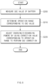
- FIG. 6 is a flowchart of a method for correcting the SOC of the battery according to another embodiment of the present invention.
- an SOC value of the battery which is charged through power supplied from a power producing device of a battery energy storage system (BESS) is measured (S200).
- the SOC value of the battery may be measured at every preset unit time.
- FIG. 3 is a graph of SOC values of the battery, which is measured at every unit time. Referring to FIG. 3 , it is seen that an SOC value of the battery is frequently changed in a range of about 0% to about 100%.
- the measured SOC value of the battery is compared to the plurality of operation ranges stored in the storage unit (see reference numeral 220 of FIG. 5 ) to determine an operation range corresponding to the measured SOC value among the plurality of operation ranges (S210).
- the plurality of operation ranges corresponding to the SOC values of the battery are stored in the storage unit 220.
- the plurality of operation ranges may be previously set to determine whether the charging/discharging of the battery is compensated.
- an x-axis in the graph may denote a time
- a y-axis in the graph may denote an SOC value of the battery.
- the SOC value of the battery may be partitively set to ranges of about 70% to about 100% (a first operation range: a), about 30% to about 70% (a second operation range: b), and about 0% to about 30% (a third operation range: c). Since there are many demands to match the present SOC value of the battery to a level of about 50%, it may be determined that the first operation state is defined as an overcharged state, the second operation range is defined as a normal range, and the third operation range is defined as an overcharged state.
- the value of each of the operation ranges is set as described above. In the present invention, the values of the operation ranges may be changed in consideration of capacity, charging efficiency, discharging resistance, and the like of the battery.
- the SOC correcting unit 240 includes a first correcting part 240a, a second correcting part 240b, and a third correcting part 240c.
- the correcting parts are operated by using charging/discharging power adjusting manners different from each other, respectively.
- the first correcting part 240a includes conditions for increasing or decreasing charging/discharging power in an exponential form.
- the second correcting part 240b includes conditions for increasing or decreasing the charging/discharging power in a stepped form.
- a third correcting part 240c includes conditions for increasing or decreasing the charging/discharging power at a predetermined ratio.
- the SOC correction is performed by using the correction value corresponding to the operation range which corresponds to the measured SOC value of the battery (S220).
- the SOC correction may adjust the charging/discharging power according to the result determined in the operation S210.
- a method for adjusting the charging/discharging power may include various methods set in the SOC correcting unit 240 and will be described with reference to embodiments.
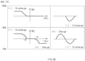
- FIGS. 8A to 8C are graphs of a method for increasing or decreasing the charging/discharging power in the exponential form.
- FIG. 8A illustrates a case in which the SOC value of the battery, which is measured in the SOC measuring unit corresponds to the first operation range a of about 70% to about 100%.
- a correction value by which the charging power is decreased in the exponential form, and the discharging power is increased in the exponential form is applied.
- the probability that the SOC value of the battery reaches about 100% may be reduced, and the battery may be reduced in capacity when the battery is designed.
- FIG. 8B illustrates a case in which the SOC value of the battery, which is measured in the SOC measuring unit corresponds to the second operation range b of about 30% to about 70%. In this case, it is determined as the normal range to maintain the present state.
- FIG. 8C illustrates a case in which the SOC value of the battery, which is measured in the SOC measuring unit corresponds to the third operation range c of about 0% to about 30%.
- a correction value by which the charging power is increased in the exponential form, and the discharging power is decreased in the exponential form is applied.
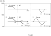
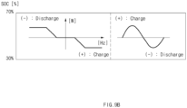
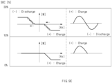
- FIGS. 9A to 9C are graphs of a method for increasing or decreasing the charging/discharging power in the stepped form.
- FIG. 9A illustrates a case in which the SOC value of the battery, which is measured in the SOC measuring unit corresponds to the first operation range a of about 70% to about 100%.
- a correction value by which the charging power is decreased in the stepped form, and the discharging power is increased in the stepped form is applied.
- FIG. 9B illustrates a case in which the SOC value of the battery, which is measured in the SOC measuring unit corresponds to the second operation range b of about 30% to about 70%. In this case, it is determined as the normal range to maintain the present state.
- FIG. 9C illustrates a case in which the SOC value of the battery, which is measured in the SOC measuring unit corresponds to the third operation range c of about 0% to about 30%.
- a correction value by which the charging power is increased in the stepped form, and the discharging power is decreased in the stepped form is applied.
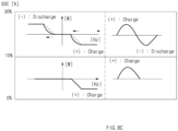
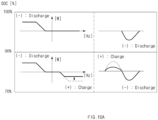
- FIGS. 10A to 10C are graphs of a method for increasing or decreasing the charging/discharging power at a predetermined ratio.
- FIG. 10A illustrates a case in which the SOC value of the battery, which is measured in the SOC measuring unit corresponds to the first operation range a of about 70% to about 100%.
- a correction value by which the charging power is decreased at a predetermined ratio is applied.
- FIG. 10B illustrates a case in which the SOC value of the battery, which is measured in the SOC measuring unit corresponds to the second operation range b of about 30% to about 70%. In this case, it is determined as the normal range to maintain the present state.
- FIG. 10C illustrates a case in which the SOC value of the battery, which is measured in the SOC measuring unit corresponds to the third operation range c of about 0% to about 30%.
- a correction value by which the discharging power is decreased at a predetermined ratio in comparison to the existing discharging power is applied.
- the SOC value of the battery may be maintained within a predetermined range.
- the probability that the SOC value of the battery reaches about 100% or about 0% may be reduced, and the battery may be reduced in capacity when the battery is designed.
Landscapes
- Engineering & Computer Science (AREA)
- Manufacturing & Machinery (AREA)
- General Chemical & Material Sciences (AREA)
- Electrochemistry (AREA)
- Chemical Kinetics & Catalysis (AREA)
- Chemical & Material Sciences (AREA)
- Power Engineering (AREA)
- Mechanical Engineering (AREA)
- Transportation (AREA)
- Life Sciences & Earth Sciences (AREA)
- Sustainable Energy (AREA)
- Sustainable Development (AREA)
- Physics & Mathematics (AREA)
- General Physics & Mathematics (AREA)
- Charge And Discharge Circuits For Batteries Or The Like (AREA)
- Secondary Cells (AREA)
Claims (12)
- System zum Aufrechterhalten eines Ladezustands (State-of-Charging, SOC) einer Batterie, die durch von einer Stromerzeugungsvorrichtung eines Batterie-Energiespeichersystems (BESS) gelieferte Energie geladen werden soll, innerhalb eines vorbestimmten Bereichs, wobei das System Folgendes umfasst:eine SOC-Messeinheit (110), die zum Messen eines SOC-Wertes der Batterie konfiguriert ist;eine Speichereinheit (120), die so konfiguriert ist, dass sie voreingestellte Betriebsbereiche speichert, um zu bestimmen, ob das Laden/Entladen der Batterie kompensiert wird;eine Bestimmungseinheit (130), die so konfiguriert ist, dass sie einen Betriebsbereich, der dem SOC-Wert der Batterie entspricht, aus den voreingestellten Betriebsbereichen bestimmt, wobei der bestimmte Betriebsbereich ein Bereich ist, auf dem eine Totzone in Lade-/Entladerichtungen basiert, wobei ein Frequenzkorrektursignalbereich, der einem Bereich der Totzone in Lade-/Entladerichtungen entspricht, verwendet wird, um einen Betrag eines an die Batterie angelegten Leistungssignals anzupassen; undeine SOC-Korrektureinheit (140), die so konfiguriert ist, dass sie die Totzone in Lade-/Entladerichtungen anpasst, um dadurch den Frequenzkorrektursignalbereich gemäß dem in der Bestimmungseinheit bestimmten Ergebnis anzupassen, um den SOC-Wert der Batterie innerhalb des vorbestimmten Bereichs zu halten;dadurch gekennzeichnet, dass das System weiter so konfiguriert ist, dass es die Werte der Betriebsbereiche entsprechend einem Zustand der Batterie oder der Umgebung ändert.
- System nach Anspruch 1, wobei die Speichereinheit (120) einen ersten Betriebsbereich, einen zweiten Betriebsbereich und einen dritten Betriebsbereich umfasst.
- System nach Anspruch 2, wobei der erste Betriebsbereich etwa 70 % bis etwa 100 % des SOC-Wertes beträgt, der zweite Betriebsbereich etwa 30 % bis etwa 70 % des SOC-Wertes beträgt und der dritte Betriebsbereich etwa 0 % bis etwa 30 % des SOC-Wertes beträgt.
- System nach Anspruch 2, wobei die SOC-Korrektureinheit (140) entsprechend den Betriebsbereichen auf voneinander verschiedene Korrekturwerte eingestellt wird.
- System nach Anspruch 4, das weiter so konfiguriert ist, dass es, wenn es in der Bestimmungseinheit als erster Betriebsbereich bestimmt wird, einen ersten Korrekturwert anwendet, um den eine Totzone in der Laderichtung erhöht wird.
- System nach Anspruch 4, das weiter so konfiguriert ist, dass es, wenn es in der Bestimmungseinheit (130) als zweiter Betriebsbereich bestimmt wird, einen zweiten Korrekturwert anwendet, um den eine Totzone in der Laderichtung erhöht wird, oder der aktuelle Zustand beibehalten wird.
- System nach Anspruch 4, das weiter so konfiguriert ist, dass es, wenn es in der Bestimmungseinheit (130) als dritter Betriebsbereich bestimmt wird, einen dritten Korrekturwert anwendet, um den eine Totzone in der Laderichtung verringert oder in der Entladerichtung erhöht wird.
- Verfahren zum Aufrechterhalten eines Ladezustands (State-of-Charging, SOC) einer Batterie, die durch von einer Stromerzeugungsvorrichtung eines Batterie-Energiespeichersystems (BESS) gelieferten Strom geladen werden soll, innerhalb eines vorbestimmten Bereichs, wobei das Verfahren Folgendes umfasst:Messen (S100) eines SOC-Wertes der Batterie;Vergleichen des SOC-Werts mit voreingestellten Betriebsbereichen, um einen Betriebsbereich zu bestimmen (S110), der dem SOC-Wert entspricht, wobei der bestimmte Betriebsbereich ein Bereich ist, auf dem eine Totzone in Lade-/Entladerichtungen basiert, wobei ein Frequenzkorrektursignalbereich, der einem Bereich der Totzone in Lade-/Entladerichtungen entspricht, verwendet wird, um einen Betrag eines an die Batterie angelegten Leistungssignals anzupassen; undEinstellen (S120) der Totzone in Lade-/Entladerichtungen, um dadurch den Frequenzkorrektursignalbereich gemäß den Bedingungen einzustellen, die dem Betriebsbereich entsprechen, der dem SOC-Wert entspricht, um den SOC-Wert der Batterie innerhalb des vorbestimmten Bereichs zu halten; dadurch gekennzeichnet, dass die Werte der Betriebsbereiche gemäß einem Zustand der Batterie oder der Umgebung geändert werden.
- Verfahren nach Anspruch 8, wobei die voreingestellten Betriebsbereiche einen ersten Betriebsbereich, einen zweiten Betriebsbereich und einen dritten Betriebsbereich umfassen, und
der erste Betriebsbereich etwa 70 % bis etwa 100 % des SOC-Werts beträgt, der zweite Betriebsbereich etwa 30 % bis etwa 70 % des SOC-Werts beträgt und der dritte Betriebsbereich etwa 0 % bis etwa 30 % des SOC-Werts beträgt. - Verfahren nach Anspruch 9, wobei, wenn es als der erste Betriebsbereich bestimmt wird, ein erster Korrekturwert angewendet wird, um den eine Totzone in der Laderichtung erhöht wird.
- Verfahren nach Anspruch 9, wobei, wenn es als der zweite Betriebsbereich bestimmt wird, ein zweiter Korrekturwert angewendet wird, um den eine Totzone in den Lade-/Entladerichtungen erhöht wird, oder der aktuelle Zustand beibehalten wird.
- Verfahren nach Anspruch 9, wobei, wenn es als der dritte Betriebsbereich bestimmt wird, ein dritter Korrekturwert angewendet wird, um den eine Totzone in der Laderichtung verringert oder in der Entladerichtung erhöht wird.
Applications Claiming Priority (3)
| Application Number | Priority Date | Filing Date | Title |
|---|---|---|---|
| KR1020140142609A KR101749383B1 (ko) | 2014-10-21 | 2014-10-21 | 배터리의 soc 보정 시스템 및 방법 |
| KR1020140142610A KR20160046550A (ko) | 2014-10-21 | 2014-10-21 | 배터리의 soc 보정 시스템 및 방법 |
| PCT/KR2015/011098 WO2016064171A1 (ko) | 2014-10-21 | 2015-10-20 | 배터리의 soc 보정 시스템 및 방법 |
Publications (3)
| Publication Number | Publication Date |
|---|---|
| EP3051656A1 EP3051656A1 (de) | 2016-08-03 |
| EP3051656A4 EP3051656A4 (de) | 2017-01-18 |
| EP3051656B1 true EP3051656B1 (de) | 2024-09-11 |
Family
ID=55761142
Family Applications (1)
| Application Number | Title | Priority Date | Filing Date |
|---|---|---|---|
| EP15837076.7A Active EP3051656B1 (de) | 2014-10-21 | 2015-10-20 | System und verfahren zur soc-korrektur einer batterie |
Country Status (6)
| Country | Link |
|---|---|
| US (1) | US9882409B2 (de) |
| EP (1) | EP3051656B1 (de) |
| CN (1) | CN105745811A (de) |
| ES (1) | ES2988721T3 (de) |
| HU (1) | HUE068575T2 (de) |
| WO (1) | WO2016064171A1 (de) |
Families Citing this family (10)
| Publication number | Priority date | Publication date | Assignee | Title |
|---|---|---|---|---|
| CN107627872B (zh) * | 2017-08-29 | 2020-01-14 | 广州小鹏汽车科技有限公司 | 基于电动汽车出行模式的电池充电控制方法和系统 |
| CN110549900B (zh) * | 2018-03-30 | 2021-06-18 | 比亚迪股份有限公司 | 电动汽车及动力电池静置之后的参数更新方法、装置 |
| CN111220919B (zh) * | 2018-11-26 | 2021-04-20 | 北汽福田汽车股份有限公司 | 电池电量检测方法、装置及车辆 |
| KR102685558B1 (ko) * | 2019-01-04 | 2024-07-15 | 주식회사 엘지에너지솔루션 | 배터리 관리 방법, 배터리 장치, 및 배터리를 포함하는 자동차 |
| KR102802132B1 (ko) * | 2019-02-20 | 2025-04-28 | 삼성에스디아이 주식회사 | 배터리 제어 장치 및 배터리 제어 방법 |
| KR102785786B1 (ko) | 2019-03-21 | 2025-03-26 | 주식회사 엘지에너지솔루션 | 배터리 뱅크 제어 장치 및 방법 |
| CN110190649B (zh) * | 2019-06-01 | 2020-12-29 | 深圳市永航新能源技术有限公司 | 一种电池容量评估校正充放电装置及校正方法 |
| CN113049961B (zh) * | 2021-02-26 | 2022-07-19 | 佛山职业技术学院 | 一种磷酸铁锂电池的dzsoc算法 |
| WO2022198564A1 (zh) * | 2021-03-25 | 2022-09-29 | 华为数字能源技术有限公司 | 一种储能系统的控制方法和储能系统 |
| CN113848484B (zh) * | 2021-09-09 | 2025-03-25 | 华为数字能源技术有限公司 | 一种储能系统和参数校准方法 |
Citations (2)
| Publication number | Priority date | Publication date | Assignee | Title |
|---|---|---|---|---|
| DE102011055232A1 (de) * | 2011-11-10 | 2013-05-16 | Evonik Industries Ag | Verfahren zur Bereitstellung von Regelleistung mit einem Energiespeicher mit variabler Totbandbreite bei der Regelleistungserbringung |
| DE102013206808A1 (de) * | 2013-04-16 | 2014-10-16 | Younicos Ag | Verfahren und Vorrichtung zur Regelung des Ladezustandes eines Batteriekraftwerks |
Family Cites Families (16)
| Publication number | Priority date | Publication date | Assignee | Title |
|---|---|---|---|---|
| US6868318B1 (en) * | 2003-10-14 | 2005-03-15 | General Motors Corporation | Method for adjusting battery power limits in a hybrid electric vehicle to provide consistent launch characteristics |
| US8314595B2 (en) | 2007-01-12 | 2012-11-20 | Ford Global Technologies, Llc | Battery equalization using a plug-in charger in a hybrid electric vehicle |
| JP4183013B1 (ja) | 2007-05-15 | 2008-11-19 | トヨタ自動車株式会社 | 車両およびその制御方法 |
| US8135532B2 (en) | 2007-11-04 | 2012-03-13 | GM Global Technology Operations LLC | Method for controlling output power of an energy storage device in a powertrain system |
| KR20110054135A (ko) * | 2009-11-17 | 2011-05-25 | 현대자동차주식회사 | 하이브리드 차량의 배터리 soc 밸런싱 제어 방법 |
| US8471520B2 (en) * | 2010-05-04 | 2013-06-25 | Xtreme Power Inc. | Managing renewable power generation |
| DE112011102334T5 (de) * | 2010-07-13 | 2013-04-18 | Honda Motor Co., Ltd. | Speicherkapazitätsmanagementsystem |
| KR101256079B1 (ko) | 2010-12-28 | 2013-04-19 | 삼성에스디아이 주식회사 | 배터리 팩의 밸런싱 방법 및 밸런싱 시스템 |
| JP2014112980A (ja) * | 2011-03-25 | 2014-06-19 | Sanyo Electric Co Ltd | バッテリモジュール、バッテリシステム、電源装置、及び、移動体 |
| JP2015512607A (ja) * | 2012-03-28 | 2015-04-27 | エアロバイロメント, インコーポレイテッドAerovironment, Inc. | 周波数反応充電システムおよび方法 |
| DE102012208461A1 (de) | 2012-05-21 | 2013-11-21 | Robert Bosch Gmbh | Verfahren und Vorrichtung zur Steuerung einer Brennkraftmaschine |
| DE102012208464B3 (de) | 2012-05-21 | 2013-07-04 | Deere & Company | Konditioniereinrichtung für einen Feldhäcksler |
| KR101337576B1 (ko) * | 2012-06-14 | 2013-12-06 | 이엔테크놀로지 주식회사 | Soc 관리를 위한 방법 및 시스템 |
| KR20140073627A (ko) * | 2012-11-30 | 2014-06-17 | 주식회사 포스코아이씨티 | 배터리 관리 장치 및 방법 |
| EP2992582B1 (de) * | 2013-04-29 | 2018-01-31 | Level Energy Ltd | Gerät und verfahren zur steuerung von gespeicherter energie |
| JP6056730B2 (ja) * | 2013-10-16 | 2017-01-11 | トヨタ自動車株式会社 | 蓄電システム |
-
2015
- 2015-10-20 US US14/917,346 patent/US9882409B2/en active Active
- 2015-10-20 HU HUE15837076A patent/HUE068575T2/hu unknown
- 2015-10-20 WO PCT/KR2015/011098 patent/WO2016064171A1/ko not_active Ceased
- 2015-10-20 CN CN201580001968.9A patent/CN105745811A/zh active Pending
- 2015-10-20 EP EP15837076.7A patent/EP3051656B1/de active Active
- 2015-10-20 ES ES15837076T patent/ES2988721T3/es active Active
Patent Citations (2)
| Publication number | Priority date | Publication date | Assignee | Title |
|---|---|---|---|---|
| DE102011055232A1 (de) * | 2011-11-10 | 2013-05-16 | Evonik Industries Ag | Verfahren zur Bereitstellung von Regelleistung mit einem Energiespeicher mit variabler Totbandbreite bei der Regelleistungserbringung |
| DE102013206808A1 (de) * | 2013-04-16 | 2014-10-16 | Younicos Ag | Verfahren und Vorrichtung zur Regelung des Ladezustandes eines Batteriekraftwerks |
Also Published As
| Publication number | Publication date |
|---|---|
| WO2016064171A1 (ko) | 2016-04-28 |
| US9882409B2 (en) | 2018-01-30 |
| US20160301234A1 (en) | 2016-10-13 |
| EP3051656A1 (de) | 2016-08-03 |
| HUE068575T2 (hu) | 2025-01-28 |
| ES2988721T3 (es) | 2024-11-21 |
| CN105745811A (zh) | 2016-07-06 |
| EP3051656A4 (de) | 2017-01-18 |
Similar Documents
| Publication | Publication Date | Title |
|---|---|---|
| EP3051656B1 (de) | System und verfahren zur soc-korrektur einer batterie | |
| JP6777510B2 (ja) | バッテリ制御方法、バッテリ制御装置、及びバッテリパック | |
| CN106716162B (zh) | 电池状态推定装置以及电源装置 | |
| US10254780B2 (en) | Method and apparatus for distributing power in energy storage system | |
| US10873201B2 (en) | Battery management apparatus and method for protecting a lithium iron phosphate cell from over-voltage using the same | |
| US10727678B2 (en) | Method for determining a combination of energy storage units that output electric energy during charging by comparing an electric quantity level of each energy storage unit to an average electric quantity after performing the charging | |
| EP3038229A1 (de) | Speicherbatterie, speicherbatteriebewertungsvorrichtung, speicherbatteriebewertungsverfahren | |
| EP3410558A1 (de) | Batteriesteuerungsvorrichtung | |
| JP2022503514A (ja) | バッテリー管理装置 | |
| EP3026752A1 (de) | Batteriepack und verfahren zur steuerung davon | |
| JP2020518965A (ja) | バッテリー充電管理装置及び方法 | |
| US10403936B2 (en) | Storage cell control system, storage cell control method, and recording medium | |
| JP2007236151A (ja) | 二次電池の充放電制御システム、電池制御装置、およびプログラム | |
| KR20210155290A (ko) | 무선 충전을 위한 배터리 관리 시스템 및 배터리 랙 | |
| WO2014103218A1 (ja) | 蓄電装置充放電システム | |
| US20230187719A1 (en) | Electric power demand adjusting device | |
| KR101583946B1 (ko) | 배터리 충전방법 | |
| KR102020044B1 (ko) | 배터리 충전 시스템 및 이를 이용한 배터리 모듈의 최대용량 충전 제어방법 | |
| CN117955140A (zh) | 功率分配方法、装置、储能电站及存储介质 | |
| EP4033631A1 (de) | Vorrichtung und verfahren zur aktualisierung von strommustern für schnelles laden sowie ein in einem speichermedium gespeichertes computerprogramm zur durchführung davon | |
| KR101491460B1 (ko) | 배터리의 액티브 셀 밸런싱 방법 및 이를 이용한 시스템 | |
| KR101915183B1 (ko) | 공통 버스를 이용한 액티브 셀 밸런싱의 기준 soc 설정 및 동작 장치 및 방법 | |
| EP4567448A1 (de) | Batterieverwaltungssystem und -verfahren sowie batteriepack damit | |
| KR101749383B1 (ko) | 배터리의 soc 보정 시스템 및 방법 | |
| KR102035674B1 (ko) | 배터리 모듈들의 전압 균일화 장치 및 방법 |
Legal Events
| Date | Code | Title | Description |
|---|---|---|---|
| PUAI | Public reference made under article 153(3) epc to a published international application that has entered the european phase |
Free format text: ORIGINAL CODE: 0009012 |
|
| 17P | Request for examination filed |
Effective date: 20160304 |
|
| AK | Designated contracting states |
Kind code of ref document: A1 Designated state(s): AL AT BE BG CH CY CZ DE DK EE ES FI FR GB GR HR HU IE IS IT LI LT LU LV MC MK MT NL NO PL PT RO RS SE SI SK SM TR |
|
| AX | Request for extension of the european patent |
Extension state: BA ME |
|
| A4 | Supplementary search report drawn up and despatched |
Effective date: 20161221 |
|
| RIC1 | Information provided on ipc code assigned before grant |
Ipc: B60L 11/18 20060101ALI20161215BHEP Ipc: H01M 10/44 20060101ALI20161215BHEP Ipc: H02J 7/00 20060101AFI20161215BHEP |
|
| DAV | Request for validation of the european patent (deleted) | ||
| DAX | Request for extension of the european patent (deleted) | ||
| STAA | Information on the status of an ep patent application or granted ep patent |
Free format text: STATUS: EXAMINATION IS IN PROGRESS |
|
| 17Q | First examination report despatched |
Effective date: 20191010 |
|
| RAP1 | Party data changed (applicant data changed or rights of an application transferred) |
Owner name: LG ENERGY SOLUTION LTD. |
|
| RAP3 | Party data changed (applicant data changed or rights of an application transferred) |
Owner name: LG ENERGY SOLUTION, LTD. |
|
| REG | Reference to a national code |
Ref country code: DE Ref legal event code: R079 Free format text: PREVIOUS MAIN CLASS: H02J0007000000 Ipc: B60L0058130000 Ref document number: 602015089882 Country of ref document: DE |
|
| GRAP | Despatch of communication of intention to grant a patent |
Free format text: ORIGINAL CODE: EPIDOSNIGR1 |
|
| STAA | Information on the status of an ep patent application or granted ep patent |
Free format text: STATUS: GRANT OF PATENT IS INTENDED |
|
| RIC1 | Information provided on ipc code assigned before grant |
Ipc: H02J 7/00 20060101ALI20231211BHEP Ipc: H02J 3/32 20060101ALI20231211BHEP Ipc: H01M 10/44 20060101ALI20231211BHEP Ipc: H01M 10/48 20060101ALI20231211BHEP Ipc: B60L 58/13 20190101AFI20231211BHEP |
|
| INTG | Intention to grant announced |
Effective date: 20240105 |
|
| GRAJ | Information related to disapproval of communication of intention to grant by the applicant or resumption of examination proceedings by the epo deleted |
Free format text: ORIGINAL CODE: EPIDOSDIGR1 |
|
| STAA | Information on the status of an ep patent application or granted ep patent |
Free format text: STATUS: EXAMINATION IS IN PROGRESS |
|
| INTC | Intention to grant announced (deleted) | ||
| GRAP | Despatch of communication of intention to grant a patent |
Free format text: ORIGINAL CODE: EPIDOSNIGR1 |
|
| STAA | Information on the status of an ep patent application or granted ep patent |
Free format text: STATUS: GRANT OF PATENT IS INTENDED |
|
| INTG | Intention to grant announced |
Effective date: 20240424 |
|
| GRAS | Grant fee paid |
Free format text: ORIGINAL CODE: EPIDOSNIGR3 |
|
| GRAA | (expected) grant |
Free format text: ORIGINAL CODE: 0009210 |
|
| STAA | Information on the status of an ep patent application or granted ep patent |
Free format text: STATUS: THE PATENT HAS BEEN GRANTED |
|
| P01 | Opt-out of the competence of the unified patent court (upc) registered |
Free format text: CASE NUMBER: APP_40031/2024 Effective date: 20240704 |
|
| AK | Designated contracting states |
Kind code of ref document: B1 Designated state(s): AL AT BE BG CH CY CZ DE DK EE ES FI FR GB GR HR HU IE IS IT LI LT LU LV MC MK MT NL NO PL PT RO RS SE SI SK SM TR |
|
| REG | Reference to a national code |
Ref country code: GB Ref legal event code: FG4D |
|
| REG | Reference to a national code |
Ref country code: CH Ref legal event code: EP |
|
| REG | Reference to a national code |
Ref country code: DE Ref legal event code: R096 Ref document number: 602015089882 Country of ref document: DE |
|
| REG | Reference to a national code |
Ref country code: IE Ref legal event code: FG4D |
|
| REG | Reference to a national code |
Ref country code: ES Ref legal event code: FG2A Ref document number: 2988721 Country of ref document: ES Kind code of ref document: T3 Effective date: 20241121 |
|
| REG | Reference to a national code |
Ref country code: LT Ref legal event code: MG9D |
|
| PG25 | Lapsed in a contracting state [announced via postgrant information from national office to epo] |
Ref country code: NO Free format text: LAPSE BECAUSE OF FAILURE TO SUBMIT A TRANSLATION OF THE DESCRIPTION OR TO PAY THE FEE WITHIN THE PRESCRIBED TIME-LIMIT Effective date: 20241211 |
|
| REG | Reference to a national code |
Ref country code: NL Ref legal event code: MP Effective date: 20240911 |
|
| PG25 | Lapsed in a contracting state [announced via postgrant information from national office to epo] |
Ref country code: GR Free format text: LAPSE BECAUSE OF FAILURE TO SUBMIT A TRANSLATION OF THE DESCRIPTION OR TO PAY THE FEE WITHIN THE PRESCRIBED TIME-LIMIT Effective date: 20241212 Ref country code: FI Free format text: LAPSE BECAUSE OF FAILURE TO SUBMIT A TRANSLATION OF THE DESCRIPTION OR TO PAY THE FEE WITHIN THE PRESCRIBED TIME-LIMIT Effective date: 20240911 |
|
| PG25 | Lapsed in a contracting state [announced via postgrant information from national office to epo] |
Ref country code: BG Free format text: LAPSE BECAUSE OF FAILURE TO SUBMIT A TRANSLATION OF THE DESCRIPTION OR TO PAY THE FEE WITHIN THE PRESCRIBED TIME-LIMIT Effective date: 20240911 |
|
| PG25 | Lapsed in a contracting state [announced via postgrant information from national office to epo] |
Ref country code: LV Free format text: LAPSE BECAUSE OF FAILURE TO SUBMIT A TRANSLATION OF THE DESCRIPTION OR TO PAY THE FEE WITHIN THE PRESCRIBED TIME-LIMIT Effective date: 20240911 |
|
| PG25 | Lapsed in a contracting state [announced via postgrant information from national office to epo] |
Ref country code: HR Free format text: LAPSE BECAUSE OF FAILURE TO SUBMIT A TRANSLATION OF THE DESCRIPTION OR TO PAY THE FEE WITHIN THE PRESCRIBED TIME-LIMIT Effective date: 20240911 |
|
| PG25 | Lapsed in a contracting state [announced via postgrant information from national office to epo] |
Ref country code: RS Free format text: LAPSE BECAUSE OF FAILURE TO SUBMIT A TRANSLATION OF THE DESCRIPTION OR TO PAY THE FEE WITHIN THE PRESCRIBED TIME-LIMIT Effective date: 20241211 |
|
| REG | Reference to a national code |
Ref country code: HU Ref legal event code: AG4A Ref document number: E068575 Country of ref document: HU |
|
| PG25 | Lapsed in a contracting state [announced via postgrant information from national office to epo] |
Ref country code: RS Free format text: LAPSE BECAUSE OF FAILURE TO SUBMIT A TRANSLATION OF THE DESCRIPTION OR TO PAY THE FEE WITHIN THE PRESCRIBED TIME-LIMIT Effective date: 20241211 Ref country code: NO Free format text: LAPSE BECAUSE OF FAILURE TO SUBMIT A TRANSLATION OF THE DESCRIPTION OR TO PAY THE FEE WITHIN THE PRESCRIBED TIME-LIMIT Effective date: 20241211 Ref country code: LV Free format text: LAPSE BECAUSE OF FAILURE TO SUBMIT A TRANSLATION OF THE DESCRIPTION OR TO PAY THE FEE WITHIN THE PRESCRIBED TIME-LIMIT Effective date: 20240911 Ref country code: HR Free format text: LAPSE BECAUSE OF FAILURE TO SUBMIT A TRANSLATION OF THE DESCRIPTION OR TO PAY THE FEE WITHIN THE PRESCRIBED TIME-LIMIT Effective date: 20240911 Ref country code: GR Free format text: LAPSE BECAUSE OF FAILURE TO SUBMIT A TRANSLATION OF THE DESCRIPTION OR TO PAY THE FEE WITHIN THE PRESCRIBED TIME-LIMIT Effective date: 20241212 Ref country code: FI Free format text: LAPSE BECAUSE OF FAILURE TO SUBMIT A TRANSLATION OF THE DESCRIPTION OR TO PAY THE FEE WITHIN THE PRESCRIBED TIME-LIMIT Effective date: 20240911 Ref country code: BG Free format text: LAPSE BECAUSE OF FAILURE TO SUBMIT A TRANSLATION OF THE DESCRIPTION OR TO PAY THE FEE WITHIN THE PRESCRIBED TIME-LIMIT Effective date: 20240911 |
|
| REG | Reference to a national code |
Ref country code: AT Ref legal event code: MK05 Ref document number: 1722422 Country of ref document: AT Kind code of ref document: T Effective date: 20240911 |
|
| PG25 | Lapsed in a contracting state [announced via postgrant information from national office to epo] |
Ref country code: NL Free format text: LAPSE BECAUSE OF FAILURE TO SUBMIT A TRANSLATION OF THE DESCRIPTION OR TO PAY THE FEE WITHIN THE PRESCRIBED TIME-LIMIT Effective date: 20240911 |
|
| PG25 | Lapsed in a contracting state [announced via postgrant information from national office to epo] |
Ref country code: IS Free format text: LAPSE BECAUSE OF FAILURE TO SUBMIT A TRANSLATION OF THE DESCRIPTION OR TO PAY THE FEE WITHIN THE PRESCRIBED TIME-LIMIT Effective date: 20250111 Ref country code: PT Free format text: LAPSE BECAUSE OF FAILURE TO SUBMIT A TRANSLATION OF THE DESCRIPTION OR TO PAY THE FEE WITHIN THE PRESCRIBED TIME-LIMIT Effective date: 20250113 |
|
| PG25 | Lapsed in a contracting state [announced via postgrant information from national office to epo] |
Ref country code: SM Free format text: LAPSE BECAUSE OF FAILURE TO SUBMIT A TRANSLATION OF THE DESCRIPTION OR TO PAY THE FEE WITHIN THE PRESCRIBED TIME-LIMIT Effective date: 20240911 Ref country code: RO Free format text: LAPSE BECAUSE OF FAILURE TO SUBMIT A TRANSLATION OF THE DESCRIPTION OR TO PAY THE FEE WITHIN THE PRESCRIBED TIME-LIMIT Effective date: 20240911 |
|
| PG25 | Lapsed in a contracting state [announced via postgrant information from national office to epo] |
Ref country code: EE Free format text: LAPSE BECAUSE OF FAILURE TO SUBMIT A TRANSLATION OF THE DESCRIPTION OR TO PAY THE FEE WITHIN THE PRESCRIBED TIME-LIMIT Effective date: 20240911 Ref country code: AT Free format text: LAPSE BECAUSE OF FAILURE TO SUBMIT A TRANSLATION OF THE DESCRIPTION OR TO PAY THE FEE WITHIN THE PRESCRIBED TIME-LIMIT Effective date: 20240911 |
|
| PG25 | Lapsed in a contracting state [announced via postgrant information from national office to epo] |
Ref country code: CZ Free format text: LAPSE BECAUSE OF FAILURE TO SUBMIT A TRANSLATION OF THE DESCRIPTION OR TO PAY THE FEE WITHIN THE PRESCRIBED TIME-LIMIT Effective date: 20240911 Ref country code: PL Free format text: LAPSE BECAUSE OF FAILURE TO SUBMIT A TRANSLATION OF THE DESCRIPTION OR TO PAY THE FEE WITHIN THE PRESCRIBED TIME-LIMIT Effective date: 20240911 |
|
| PG25 | Lapsed in a contracting state [announced via postgrant information from national office to epo] |
Ref country code: SK Free format text: LAPSE BECAUSE OF FAILURE TO SUBMIT A TRANSLATION OF THE DESCRIPTION OR TO PAY THE FEE WITHIN THE PRESCRIBED TIME-LIMIT Effective date: 20240911 Ref country code: IT Free format text: LAPSE BECAUSE OF FAILURE TO SUBMIT A TRANSLATION OF THE DESCRIPTION OR TO PAY THE FEE WITHIN THE PRESCRIBED TIME-LIMIT Effective date: 20240911 |
|
| REG | Reference to a national code |
Ref country code: CH Ref legal event code: PL |
|
| REG | Reference to a national code |
Ref country code: DE Ref legal event code: R097 Ref document number: 602015089882 Country of ref document: DE |
|
| PG25 | Lapsed in a contracting state [announced via postgrant information from national office to epo] |
Ref country code: MC Free format text: LAPSE BECAUSE OF FAILURE TO SUBMIT A TRANSLATION OF THE DESCRIPTION OR TO PAY THE FEE WITHIN THE PRESCRIBED TIME-LIMIT Effective date: 20240911 |
|
| PG25 | Lapsed in a contracting state [announced via postgrant information from national office to epo] |
Ref country code: DK Free format text: LAPSE BECAUSE OF FAILURE TO SUBMIT A TRANSLATION OF THE DESCRIPTION OR TO PAY THE FEE WITHIN THE PRESCRIBED TIME-LIMIT Effective date: 20240911 |
|
| PG25 | Lapsed in a contracting state [announced via postgrant information from national office to epo] |
Ref country code: LU Free format text: LAPSE BECAUSE OF NON-PAYMENT OF DUE FEES Effective date: 20241020 |
|
| PLBE | No opposition filed within time limit |
Free format text: ORIGINAL CODE: 0009261 |
|
| STAA | Information on the status of an ep patent application or granted ep patent |
Free format text: STATUS: NO OPPOSITION FILED WITHIN TIME LIMIT |
|
| PG25 | Lapsed in a contracting state [announced via postgrant information from national office to epo] |
Ref country code: CH Free format text: LAPSE BECAUSE OF NON-PAYMENT OF DUE FEES Effective date: 20241031 |
|
| 26N | No opposition filed |
Effective date: 20250612 |
|
| PG25 | Lapsed in a contracting state [announced via postgrant information from national office to epo] |
Ref country code: SE Free format text: LAPSE BECAUSE OF FAILURE TO SUBMIT A TRANSLATION OF THE DESCRIPTION OR TO PAY THE FEE WITHIN THE PRESCRIBED TIME-LIMIT Effective date: 20240911 |
|
| PGFP | Annual fee paid to national office [announced via postgrant information from national office to epo] |
Ref country code: BE Payment date: 20250922 Year of fee payment: 11 Ref country code: GB Payment date: 20250922 Year of fee payment: 11 |
|
| PGFP | Annual fee paid to national office [announced via postgrant information from national office to epo] |
Ref country code: FR Payment date: 20250925 Year of fee payment: 11 |
|
| PG25 | Lapsed in a contracting state [announced via postgrant information from national office to epo] |
Ref country code: IE Free format text: LAPSE BECAUSE OF NON-PAYMENT OF DUE FEES Effective date: 20241020 |
|
| PGFP | Annual fee paid to national office [announced via postgrant information from national office to epo] |
Ref country code: HU Payment date: 20251029 Year of fee payment: 11 |
|
| PGFP | Annual fee paid to national office [announced via postgrant information from national office to epo] |
Ref country code: DE Payment date: 20250922 Year of fee payment: 11 |
|
| PG25 | Lapsed in a contracting state [announced via postgrant information from national office to epo] |
Ref country code: CY Free format text: LAPSE BECAUSE OF FAILURE TO SUBMIT A TRANSLATION OF THE DESCRIPTION OR TO PAY THE FEE WITHIN THE PRESCRIBED TIME-LIMIT; INVALID AB INITIO Effective date: 20151020 |
|
| PGFP | Annual fee paid to national office [announced via postgrant information from national office to epo] |
Ref country code: ES Payment date: 20251117 Year of fee payment: 11 |