EP4567448A1 - Batterieverwaltungssystem und -verfahren sowie batteriepack damit - Google Patents
Batterieverwaltungssystem und -verfahren sowie batteriepack damit Download PDFInfo
- Publication number
- EP4567448A1 EP4567448A1 EP23872841.4A EP23872841A EP4567448A1 EP 4567448 A1 EP4567448 A1 EP 4567448A1 EP 23872841 A EP23872841 A EP 23872841A EP 4567448 A1 EP4567448 A1 EP 4567448A1
- Authority
- EP
- European Patent Office
- Prior art keywords
- voltage
- battery
- cell
- negative electrode
- battery cell
- Prior art date
- Legal status (The legal status is an assumption and is not a legal conclusion. Google has not performed a legal analysis and makes no representation as to the accuracy of the status listed.)
- Pending
Links
Images


Classifications
-
- G—PHYSICS
- G01—MEASURING; TESTING
- G01R—MEASURING ELECTRIC VARIABLES; MEASURING MAGNETIC VARIABLES
- G01R31/00—Arrangements for testing electric properties; Arrangements for locating electric faults; Arrangements for electrical testing characterised by what is being tested not provided for elsewhere
- G01R31/36—Arrangements for testing, measuring or monitoring the electrical condition of accumulators or electric batteries, e.g. capacity or state of charge [SoC]
- G01R31/396—Acquisition or processing of data for testing or for monitoring individual cells or groups of cells within a battery
-
- G—PHYSICS
- G01—MEASURING; TESTING
- G01R—MEASURING ELECTRIC VARIABLES; MEASURING MAGNETIC VARIABLES
- G01R19/00—Arrangements for measuring currents or voltages or for indicating presence or sign thereof
- G01R19/10—Measuring sum, difference or ratio
-
- G—PHYSICS
- G01—MEASURING; TESTING
- G01R—MEASURING ELECTRIC VARIABLES; MEASURING MAGNETIC VARIABLES
- G01R31/00—Arrangements for testing electric properties; Arrangements for locating electric faults; Arrangements for electrical testing characterised by what is being tested not provided for elsewhere
- G01R31/36—Arrangements for testing, measuring or monitoring the electrical condition of accumulators or electric batteries, e.g. capacity or state of charge [SoC]
- G01R31/374—Arrangements for testing, measuring or monitoring the electrical condition of accumulators or electric batteries, e.g. capacity or state of charge [SoC] with means for correcting the measurement for temperature or ageing
-
- G—PHYSICS
- G01—MEASURING; TESTING
- G01R—MEASURING ELECTRIC VARIABLES; MEASURING MAGNETIC VARIABLES
- G01R31/00—Arrangements for testing electric properties; Arrangements for locating electric faults; Arrangements for electrical testing characterised by what is being tested not provided for elsewhere
- G01R31/36—Arrangements for testing, measuring or monitoring the electrical condition of accumulators or electric batteries, e.g. capacity or state of charge [SoC]
- G01R31/382—Arrangements for monitoring battery or accumulator variables, e.g. SoC
- G01R31/3835—Arrangements for monitoring battery or accumulator variables, e.g. SoC involving only voltage measurements
-
- G—PHYSICS
- G01—MEASURING; TESTING
- G01R—MEASURING ELECTRIC VARIABLES; MEASURING MAGNETIC VARIABLES
- G01R31/00—Arrangements for testing electric properties; Arrangements for locating electric faults; Arrangements for electrical testing characterised by what is being tested not provided for elsewhere
- G01R31/36—Arrangements for testing, measuring or monitoring the electrical condition of accumulators or electric batteries, e.g. capacity or state of charge [SoC]
- G01R31/392—Determining battery ageing or deterioration, e.g. state of health
-
- Y—GENERAL TAGGING OF NEW TECHNOLOGICAL DEVELOPMENTS; GENERAL TAGGING OF CROSS-SECTIONAL TECHNOLOGIES SPANNING OVER SEVERAL SECTIONS OF THE IPC; TECHNICAL SUBJECTS COVERED BY FORMER USPC CROSS-REFERENCE ART COLLECTIONS [XRACs] AND DIGESTS
- Y02—TECHNOLOGIES OR APPLICATIONS FOR MITIGATION OR ADAPTATION AGAINST CLIMATE CHANGE
- Y02E—REDUCTION OF GREENHOUSE GAS [GHG] EMISSIONS, RELATED TO ENERGY GENERATION, TRANSMISSION OR DISTRIBUTION
- Y02E60/00—Enabling technologies; Technologies with a potential or indirect contribution to GHG emissions mitigation
- Y02E60/10—Energy storage using batteries
Definitions
- the present invention relates to a system and method for managing a battery, and a battery pack including the system, and more particularly, to a system and method for managing a battery, capable of accurately measuring characteristics of a battery cell, and a battery pack including the system.
- Secondary batteries are used as a battery pack including a battery module in which a plurality of battery cells are connected to each other in series and/or parallel. States and operations of the battery pack are managed and controlled by a battery management system.
- the battery management system may measure electrical characteristics of the battery cells, and determine a state of the battery based on the measured characteristics. However, when the electrical characteristics of the battery cells are not accurately measured, the state of the battery may not be properly checked.
- Embodiments according to the present invention provide a system and method for managing a battery, capable of accurately measuring characteristics of a battery cell, and a battery pack including the system.
- a battery pack may include: a battery module including a battery cell provided in plurality; at least one reference cell including more electrodes than the battery cell; a battery management system that controls the battery cell and the reference cell, wherein the battery management system measures a first voltage of the battery cell, measures a second voltage of the reference cell, and determines a state of the battery module based on a deviation between the first voltage and the second voltage.
- each of the plurality of battery cells may include a first negative electrode and a first positive electrode
- the reference cell may include a second negative electrode, a second positive electrode, and a reference electrode
- the first voltage may be a first negative electrode voltage of the battery cell
- the second voltage may be a second negative electrode voltage corresponding to a difference in potential between the reference electrode and the second negative electrode of the reference cell.
- the battery management system may measure the first negative electrode voltage while charging the battery cell, and measure the second negative electrode voltage while charging the reference cell.
- the first voltage may be a first cell voltage corresponding to a difference in potential between the first positive electrode and the first negative electrode
- the second voltage may be a second cell voltage corresponding to a difference between a second positive electrode voltage and a second negative electrode voltage
- the second positive electrode voltage corresponds to a difference in potential between the reference electrode and the second positive electrode
- the second negative electrode voltage corresponds to a difference in potential between the reference electrode and the second negative electrode
- the battery management system may measure the first cell voltage while charging the battery cell, and measure the second cell voltage while charging the reference cell.
- the battery management system may estimate a state of health (SOH) of the battery module based on a deviation between the first voltage and the second voltage, and determine a state of the plurality of battery cells based on the estimated SOH.
- SOH state of health
- the battery management system may correct the first voltage based on a deviation between the first voltage and the second voltage, estimate a state of health (SOH) of the battery module based on the corrected first voltage, and determine a state of each of the plurality of battery cells based on the estimated SOH.
- SOH state of health
- a battery management system may include: a measuring part that measures a first voltage of a battery cell, which is provided in plurality and comprised in a battery module, and measures a second voltage of at least one reference cell which comprises more electrodes than the battery cell; and a controller that determines a state of each of the plurality of battery cells based on a deviation between the first voltage and the second voltage.
- the measuring part may measure the first voltage while charging the battery cell including a first negative electrode and a first positive electrode, and measure the second voltage while charging the reference cell comprising a second negative electrode, a second positive electrode, and a reference electrode.
- a battery management method may include: measuring a first voltage of a battery cell provided in plurality and included in a battery module; measuring a second voltage of at least one reference cell that includes more electrodes than the battery cell; and determining a state of each of the plurality of battery cells based on a deviation between the first voltage and the second voltage.
- the electrical characteristics (e.g., the negative electrode voltage and the cell voltage) of the battery cell may be accurately measured through the reference electrode included in the reference cell.
- the state of health of the battery cell may be accurately measured based on the at least one of the negative electrode voltage or the cell voltage.
- the cell balancing may be performed.
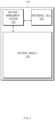
- FIG. 1 is a block diagram illustrating a battery pack according to the present invention.
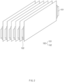
- FIG. 2 is a perspective view illustrating a battery cell included in a battery module illustrated in FIG. 1 .
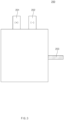
- FIG. 3 is a plan view illustrating a reference cell included in the battery pack illustrated in FIG. 1 .
- a battery pack 110 may include a reference cell 200, a battery module 130, and a battery management system 120.
- the battery module 130 may be provided in plurality, and each of the plurality of battery modules 130 may be provided in the form of a stack in which a plurality of battery cells 100 are stacked. As illustrated in FIG. 2 , each of the plurality of battery cells 100 may have a two-electrode structure including a first positive electrode 101 (or working electrode) and a first negative electrode 102 (or counter electrode).
- the reference cell 200 may be provided in at least one.
- the reference cell 200 may include more electrodes than the battery cell 100.
- the reference cell 200 may have a three-electrode structure including a second positive electrode 201, a second negative electrode 202, and a reference electrode 203.
- the reference electrode 203 may be used as a potential standard when measuring a relative value of an electrode potential. As current flows between the second positive electrode 201 and the second negative electrode 202, and the current hardly flows through the reference electrode 203, potential of the reference electrode 203 itself may not change. When measuring a second negative electrode voltage corresponding to a difference in potential between the reference electrode 203 and the second negative electrode 202 of the reference cell 200, the second negative electrode voltage may be precisely measured because the potential of the reference electrode 203 does not change. When measuring a second positive electrode voltage corresponding to a difference in potential between the reference electrode 203 and the second positive electrode 201 of the reference cell 200, the second positive electrode voltage may be precisely measured because the potential of the reference electrode 203 itself does not change.
- the battery management system 120 may include a plurality of terminals as interfaces that receive values obtained by measuring various parameters, a circuit connected to these terminals to perform processing of the received values, and the like.
- the battery management system 120 may monitor voltages, current, temperatures, or the like of each of the battery cell 100 included in the battery module 130 and the reference cell 200, to manage and control the battery cells so as to prevent overcharge, overdischarge, and the like, of the battery cell 100.
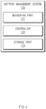
- FIG. 4 is a detailed block diagram illustrating the battery management system illustrated in FIG. 1 .
- the battery management system 120 may include a measuring part 121, a controller 122, and a storage part 123.
- the measuring part 121 may measure a first voltage of a battery cell (e.g., the battery cell 100 in FIG. 2 ), and measure a second voltage of a reference cell (e.g., the reference cell 200 in FIG. 3 ).
- the measuring part 121 may measure a first negative electrode voltage (or first voltage) of the battery cell while charging the battery cell.
- the measuring part 121 may measure the first negative electrode voltage corresponding to a difference between potential of a first negative electrode of the battery cell and reference potential (e.g., 0 V).
- the measuring part 121 may measure a second negative electrode voltage (or second voltage) corresponding to a difference in potential between a reference electrode and a second negative electrode of the reference cell while charging the reference cell.
- the measuring part 121 may measure the first negative electrode voltage in an opened state of the battery cell, and measure the second negative electrode voltage in an opened state of the reference cell.
- the controller 122 may be configured to calculate a deviation between the first negative electrode voltage of the battery cell and the second negative electrode voltage of the reference cell.
- the controller 122 may be communicatively connected to the measuring part 121 in a wired and/or wireless manner.
- the controller 122 may receive the first negative electrode voltage and the second negative electrode voltage from the measuring part 121, and calculate a voltage deviation between the received first negative electrode voltage and second negative electrode voltage.
- the controller 122 may accurately correct the first negative electrode voltage based on the voltage deviation between the first negative electrode voltage and the second negative electrode voltage.
- first positive electrode potential is changed in a state in which current flows between the first positive electrode and the first negative electrode of the battery cell, first negative electrode potential may be also changed, and thus the first negative electrode voltage is difficult to accurately measure.
- the second negative electrode voltage may be accurately measured compared to the battery cell. Accordingly, the controller 122 may accurately calculate the first negative electrode voltage by correcting the first negative electrode voltage based on the deviation between the first negative electrode voltage and the second negative electrode voltage, which are measured through the measuring part.
- the controller 122 may estimate a state of health (SOH) of each of the battery module and the battery pack, which include the battery cell, based on the corrected first negative electrode voltage.
- the controller 122 may estimate the SOH of each of the battery module and the battery pack based on data of a correlation between a pre-measured first negative electrode voltage and SOH.
- Data of a correlation between a corrected first negative electrode voltage and SOH may be pre-stored in the storage part 123.
- the data of the correlation between the corrected first negative electrode voltage and the SOH may be values obtained in advance through at least one pre-estimation.
- the data of the correlation between the corrected first negative electrode voltage and the SOH may be re-estimated at fixed intervals and periodically updated.
- the controller 122 may estimate a state of health (SOH) of each of the battery module and the battery pack, which include the battery cell, based on the voltage deviation between the first negative electrode voltage and the second negative electrode voltage.
- the controller 122 may estimate the SOH of each of the battery module and the battery pack based on data of a correlation between a voltage deviation between pre-measured negative electrode voltages and SOH.
- the data of a correlation between a voltage deviation between negative electrode voltages of the battery cell and the reference cell and SOH may be pre-stored in the storage part 123.
- the data of the correlation between the deviation between the negative electrode voltages of the battery cell and the reference cell and the SOH may be values obtained in advance through at least one pre-estimation.
- the data of the correlation between the deviation between negative electrode voltages of the battery cell and the reference cell and the SOH may be re-estimated at fixed intervals and periodically updated.
- the controller 122 may determine a state of each of the battery module and the battery pack, which include the battery cell, based on the estimated SOH.
- the controller 122 may predict a degree of degradation, replacement time, lifetime, and the like of the battery cell based on the estimated SOH.
- the controller 122 may select a battery cell, which is subject to balancing, based on the SOH of each of the plurality of battery cells. For example, the controller 122 may compare the respective SOHs of the plurality of battery cells, and select, as an object to be balanced, a battery cell of which the SOH goes beyond a threshold.
- the controller 122 may perform balancing on the battery cell selected as an object to be balanced. Accordingly, the battery module and the battery pack, which include the battery cell, may be safely managed.
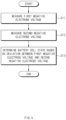
- FIG. 5 is a flowchart illustrating a battery management method according to a first embodiment of the present invention.
- the first negative electrode voltage of the battery cell may be decreased due to an electrochemical phenomenon in the battery cell.
- the battery cell is continuously charged in a state in which negative electrode potential of the battery cell is low (e.g., 0 V or less)
- a phenomenon in which the negative electrode is plated with a metal may occur to cause a reduction in lifetime of the battery cell.
- the present invention may measure the first negative electrode voltage of the battery cell so that the negative electrode potential of the battery cell is greater than the reference potential during charging of the battery cell.
- the measuring part may measure a second negative electrode voltage (or the second voltage) of a reference cell (e.g., the reference cell 200 in FIG. 3 ) while charging the reference cell.
- the second negative electrode voltage may correspond to a difference in potential between a reference electrode (e.g., the reference electrode 203 in FIG. 3 ) and a second negative electrode (e.g., the second negative electrode 202 in FIG. 3 ) of the reference cell.
- a controller may calculate a voltage deviation between the first negative electrode voltage of the battery cell and the second negative electrode voltage of the reference cell, correct the first negative electrode voltage based on the calculated voltage deviation, and estimate a state of health (SOH) of each of the battery module and the battery pack, which include the battery cell, based on the corrected first negative electrode voltage.
- SOH state of health
- the controller may calculate a voltage deviation between the first negative electrode voltage of the battery cell and the second negative electrode voltage of the reference cell, and estimate a state of health (SOH) of each of the battery module and the battery pack, which include the battery cell, based on the calculated voltage deviation.
- SOH state of health
- the controller may predict a degree of degradation, replacement time, lifetime, and the like of the battery cell based on the estimated SOH.
- the controller may control charging for the battery pack so that the first negative electrode voltage of the battery cell, which has been measured (or corrected) through the measuring part, is maintained at a fixed level or higher (or greater than the reference potential). Accordingly, the lifetime characteristics of the battery pack may be improved.
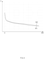
- FIG. 6 is a graph illustrating a negative electrode voltage according to a change in state of charge (SOC) of each of the battery cell and the reference cell according to the first embodiment of the present invention.
- a horizontal axis may indicate a SOC (or remaining capacity) of the battery
- a vertical axis may indicate a negative electrode voltage of each of the battery cell and the reference cell.
- the SOC being 0 may mean that the negative electrode voltage reaches a predetermined upper limit voltage, and the battery cell is in a fully discharged state
- the SOC gradually increasing from 0 may mean that as the negative electrode voltage gradually reaches a predetermined lower limit voltage, the battery cell approaches a fully charged state.
- a controller may generate a first negative electrode voltage profile 501 in which as a charged state of the battery cell increases (or an amount of lithium ions stored in the battery cell increases), the first negative electrode voltage gradually decreases.
- the controller may generate a second negative electrode voltage profile 502 in which as a charged state of the reference cell increases (or an amount of lithium ions stored in the reference cell increases), the second negative electrode voltage gradually decreases.
- the first negative electrode voltage profile 501 and the second negative electrode voltage profile 501 may be generated through charging experiments on the battery cell and the reference cell.
- the controller may calculate a voltage deviation between the first negative electrode voltage and the second negative electrode voltage, based on the first negative electrode voltage profile 501 and the second negative electrode voltage profile 502.
- the controller may estimate a state of health (SOH) of the battery cell based on the calculated voltage deviation.
- FIG. 7 is a flowchart illustrating a battery management method according to a second embodiment of the present invention.
- a measuring part may measure a first cell voltage (e.g., the first voltage) of a battery cell (e.g., the battery cell 100 in FIG. 2 ) while charging the battery cell.
- the first cell voltage may be a voltage corresponding to a difference in potential between a first positive electrode (e.g., the first positive electrode 101 in FIG. 2 ) and a first negative electrode (e.g., the first negative electrode 102 in FIG. 2 ) of the battery cell.
- a measuring part may measure a second cell voltage (or the second voltage) of a reference cell (e.g., the reference cell 200 in FIG. 3 ) while charging the reference cell.
- the second cell voltage may be a voltage corresponding to a difference between a second positive electrode voltage and a second negative electrode voltage of the reference cell.
- the second positive electrode voltage may be a voltage corresponding to a difference in potential between a reference electrode (e.g., the reference electrode 203 in FIG. 3 ) and a second positive electrode (e.g., the second positive electrode 201 in FIG. 3 ) of the reference cell.
- the second negative electrode voltage may be a voltage corresponding to a difference in potential between the reference electrode of the reference cell and a second negative electrode (e.g., the second negative electrode 202 in FIG. 3 ).
- a controller may calculate a voltage deviation between the first cell voltage of the battery cell and the second cell voltage of the reference cell, correct the first cell voltage based on the calculated voltage deviation, and estimate a state of health (SOH) of each of the battery module and the battery pack, which include the battery cell, based on the corrected first cell voltage.
- SOH state of health
- the controller may calculate a voltage deviation between the first cell voltage of the battery cell and the second cell voltage of the reference cell, and estimate a state of health (SOH) of each of the battery module and the battery pack, which include the battery cell, based on the calculated voltage deviation.
- SOH state of health
- the controller 122 may predict a degree of degradation, replacement time, lifetime, and the like of the battery cell based on the estimated SOH.
- FIG. 8 is a graph illustrating a negative electrode voltage according to a change in state of charge (SOC) of each of a battery cell and a reference cell according to the second embodiment of the present invention.
- a horizontal axis may indicate a SOC (or remaining capacity) of the battery
- a vertical axis may indicate a cell voltage of each of the battery cell and the reference cell.
- a controller may generate a first cell voltage profile 711 in which as a charged state of the battery cell increases (or an amount of lithium ions stored in the battery cell increases), the first cell voltage gradually increases.
- the controller may generate a second cell voltage profile 712 in which as a charged state of the reference cell increases (or an amount of lithium ions stored in the reference cell increases), the second cell voltage gradually increases.
- the first cell voltage profile 711 and the second cell voltage profile 712 may be generated through charging experiments on the battery cell and the reference cell.
- the controller may calculate a voltage deviation between the first cell voltage and the second cell voltage, based on the first cell voltage profile 711 and the second cell voltage profile 712.
- the controller may accurately measure a state of health (SOH) of the battery cell based on the calculated voltage deviation.
- SOH state of health
- the foregoing battery management system and battery management method are not limited to the embodiments described with reference to the drawings, respectively, and the respective structures described in the drawings may be applied in combination with each other.
- the battery management system according to the present invention may be employed in combination with the management method described with reference to FIG. 5 , or with the management method described with reference to FIG. 7 .
- the battery cell and the reference cell according to the present invention are described with examples of pouch type structures, but are not limited thereto.
- the battery cell and the reference cell may be applied to cylindrical type or prismatic type structures.
- the foregoing battery pack may be applied to various devices.
- the battery pack may be applied to transport means such as electric bikes, electric vehicles, or hybrid vehicles.
- the battery pack is not limited thereto, and may be applicable to various devices that may use a battery pack.
Landscapes
- Physics & Mathematics (AREA)
- General Physics & Mathematics (AREA)
- Secondary Cells (AREA)
- Charge And Discharge Circuits For Batteries Or The Like (AREA)
- Tests Of Electric Status Of Batteries (AREA)
Applications Claiming Priority (2)
| Application Number | Priority Date | Filing Date | Title |
|---|---|---|---|
| KR1020220125848A KR20240045909A (ko) | 2022-09-30 | 2022-09-30 | 배터리 관리 시스템 및 방법과 그를 포함하는 배터리 팩 |
| PCT/KR2023/013372 WO2024071721A1 (ko) | 2022-09-30 | 2023-09-06 | 배터리 관리 시스템 및 방법과 그를 포함하는 배터리 팩 |
Publications (2)
| Publication Number | Publication Date |
|---|---|
| EP4567448A1 true EP4567448A1 (de) | 2025-06-11 |
| EP4567448A4 EP4567448A4 (de) | 2025-12-03 |
Family
ID=90478401
Family Applications (1)
| Application Number | Title | Priority Date | Filing Date |
|---|---|---|---|
| EP23872841.4A Pending EP4567448A4 (de) | 2022-09-30 | 2023-09-06 | Batterieverwaltungssystem und -verfahren sowie batteriepack damit |
Country Status (5)
| Country | Link |
|---|---|
| EP (1) | EP4567448A4 (de) |
| JP (1) | JP2025532098A (de) |
| KR (1) | KR20240045909A (de) |
| CN (1) | CN119948347A (de) |
| WO (1) | WO2024071721A1 (de) |
Families Citing this family (1)
| Publication number | Priority date | Publication date | Assignee | Title |
|---|---|---|---|---|
| CN119420021A (zh) * | 2024-10-08 | 2025-02-11 | 中国科学技术大学 | 一种水系钠离子电池储能电站智慧管控系统和方法 |
Family Cites Families (7)
| Publication number | Priority date | Publication date | Assignee | Title |
|---|---|---|---|---|
| KR20100075913A (ko) * | 2007-09-14 | 2010-07-05 | 에이일이삼 시스템즈 인코포레이티드 | 건강 상태의 모니터링을 위한 기준 전극을 갖는 리튬 재충전 가능한 셀 |
| KR101681968B1 (ko) * | 2013-11-26 | 2016-12-02 | 주식회사 엘지화학 | 이차 전지 평가 장치 |
| KR101610908B1 (ko) * | 2014-11-17 | 2016-04-20 | 현대오트론 주식회사 | 배터리 전압 측정회로의 진단 장치 및 그 방법 |
| CN113272667B (zh) * | 2018-08-06 | 2025-01-21 | 密执安州立大学董事会 | 锂离子电池的电极诊断 |
| KR20210106164A (ko) * | 2020-02-20 | 2021-08-30 | 한국전기연구원 | 기준전지 및 이를 이용한 셀 전위 측정장치 |
| EP3965198B1 (de) * | 2020-07-07 | 2026-01-28 | Samsung SDI Co., Ltd. | Online-messung des anodenpotenzials zur maximierung der ladeleistung bei niedrigen temperaturen |
| US11996727B2 (en) * | 2020-07-07 | 2024-05-28 | Samsung Sdi Co., Ltd. | Online measurement of anode potential for the maximization of charging power at low temperatures |
-
2022
- 2022-09-30 KR KR1020220125848A patent/KR20240045909A/ko active Pending
-
2023
- 2023-09-06 WO PCT/KR2023/013372 patent/WO2024071721A1/ko not_active Ceased
- 2023-09-06 JP JP2025517215A patent/JP2025532098A/ja active Pending
- 2023-09-06 CN CN202380062766.XA patent/CN119948347A/zh active Pending
- 2023-09-06 EP EP23872841.4A patent/EP4567448A4/de active Pending
Also Published As
| Publication number | Publication date |
|---|---|
| EP4567448A4 (de) | 2025-12-03 |
| KR20240045909A (ko) | 2024-04-08 |
| WO2024071721A1 (ko) | 2024-04-04 |
| CN119948347A (zh) | 2025-05-06 |
| JP2025532098A (ja) | 2025-09-29 |
Similar Documents
| Publication | Publication Date | Title |
|---|---|---|
| KR101985812B1 (ko) | 전지 충전 한계 예측 방법과 이를 이용한 전지 급속 충전 방법 및 장치 | |
| EP3690462B1 (de) | Vorrichtung und verfahren zur batterieverwaltung | |
| KR102259967B1 (ko) | 배터리 충전관리 장치 및 방법 | |
| US11011920B2 (en) | Energy storage apparatus for engine start-up, method for controlling the same, and vehicle | |
| US10873201B2 (en) | Battery management apparatus and method for protecting a lithium iron phosphate cell from over-voltage using the same | |
| EP4016698A1 (de) | Vorrichtung und verfahren zur steuerung des betriebs einer sekundärbatterie durch verwendung des relativen alterungsgrades der elektrode | |
| KR101776546B1 (ko) | 전지 시스템 | |
| KR101783918B1 (ko) | 이차 전지의 저항 추정 장치 및 방법 | |
| JPH07255134A (ja) | 2次電池の直列接続回路 | |
| JP2016091613A (ja) | 電池システム及び容量回復方法 | |
| US12449485B2 (en) | Battery management apparatus and method | |
| KR20230017598A (ko) | 복수의 배터리 셀들을 충전하는 방법 및 그 방법을 수행하는 제어 장치 | |
| EP3839532B1 (de) | Vorrichtung und verfahren zur bestimmung des ladezustandes | |
| EP4446760A1 (de) | Vorrichtung zur berechnung der ladetiefe einer batterie und betriebsverfahren dafür | |
| KR100964316B1 (ko) | 배터리 셀 밸런싱 시스템, 그 방법 및 이를 기록한기록매체 | |
| EP4567448A1 (de) | Batterieverwaltungssystem und -verfahren sowie batteriepack damit | |
| US10444291B2 (en) | Method for determining a potential of an anode and/or a potential of a cathode in a battery cell | |
| US10605871B2 (en) | Method and device for determining state of rechargeable battery | |
| KR20210045706A (ko) | 충전 프로파일을 이용한 인텔리전트 배터리 충방전 장치 및 방법 | |
| US12345769B2 (en) | Method for determining the capacity of an electrical energy storage unit | |
| KR101749383B1 (ko) | 배터리의 soc 보정 시스템 및 방법 | |
| US20250283946A1 (en) | Reference electrode management for a battery cell | |
| EP4693807A1 (de) | Vorrichtung und verfahren zur erzeugung eines leerlaufspannungsprofils | |
| WO2021014506A1 (ja) | 充放電制御装置および充放電制御方法 | |
| US20250264539A1 (en) | Apparatus and method for estimating capacity of battery |
Legal Events
| Date | Code | Title | Description |
|---|---|---|---|
| STAA | Information on the status of an ep patent application or granted ep patent |
Free format text: STATUS: THE INTERNATIONAL PUBLICATION HAS BEEN MADE |
|
| PUAI | Public reference made under article 153(3) epc to a published international application that has entered the european phase |
Free format text: ORIGINAL CODE: 0009012 |
|
| STAA | Information on the status of an ep patent application or granted ep patent |
Free format text: STATUS: REQUEST FOR EXAMINATION WAS MADE |
|
| 17P | Request for examination filed |
Effective date: 20250304 |
|
| AK | Designated contracting states |
Kind code of ref document: A1 Designated state(s): AL AT BE BG CH CY CZ DE DK EE ES FI FR GB GR HR HU IE IS IT LI LT LU LV MC ME MK MT NL NO PL PT RO RS SE SI SK SM TR |
|
| A4 | Supplementary search report drawn up and despatched |
Effective date: 20251105 |
|
| RIC1 | Information provided on ipc code assigned before grant |
Ipc: G01R 31/396 20190101AFI20251030BHEP Ipc: G01R 31/3835 20190101ALI20251030BHEP Ipc: G01R 19/10 20060101ALI20251030BHEP Ipc: G01R 31/374 20190101ALI20251030BHEP Ipc: G01R 31/392 20190101ALI20251030BHEP |
|
| DAV | Request for validation of the european patent (deleted) | ||
| DAX | Request for extension of the european patent (deleted) |