EP3051655A1 - Schutzschaltungsverfahren und -vorrichtung, ladevorrichtung und computerspeichermedium - Google Patents
Schutzschaltungsverfahren und -vorrichtung, ladevorrichtung und computerspeichermedium Download PDFInfo
- Publication number
- EP3051655A1 EP3051655A1 EP14847316.8A EP14847316A EP3051655A1 EP 3051655 A1 EP3051655 A1 EP 3051655A1 EP 14847316 A EP14847316 A EP 14847316A EP 3051655 A1 EP3051655 A1 EP 3051655A1
- Authority
- EP
- European Patent Office
- Prior art keywords
- current
- voltage
- value
- processed
- circuit protection
- Prior art date
- Legal status (The legal status is an assumption and is not a legal conclusion. Google has not performed a legal analysis and makes no representation as to the accuracy of the status listed.)
- Withdrawn
Links
Images


Classifications
-
- H02J7/60—
-
- H—ELECTRICITY
- H02—GENERATION; CONVERSION OR DISTRIBUTION OF ELECTRIC POWER
- H02J—CIRCUIT ARRANGEMENTS OR SYSTEMS FOR SUPPLYING OR DISTRIBUTING ELECTRIC POWER; SYSTEMS FOR STORING ELECTRIC ENERGY
- H02J50/00—Circuit arrangements or systems for wireless supply or distribution of electric power
- H02J50/10—Circuit arrangements or systems for wireless supply or distribution of electric power using inductive coupling
-
- H—ELECTRICITY
- H02—GENERATION; CONVERSION OR DISTRIBUTION OF ELECTRIC POWER
- H02J—CIRCUIT ARRANGEMENTS OR SYSTEMS FOR SUPPLYING OR DISTRIBUTING ELECTRIC POWER; SYSTEMS FOR STORING ELECTRIC ENERGY
- H02J7/00—Circuit arrangements for charging or depolarising batteries or for supplying loads from batteries
-
- H—ELECTRICITY
- H02—GENERATION; CONVERSION OR DISTRIBUTION OF ELECTRIC POWER
- H02J—CIRCUIT ARRANGEMENTS OR SYSTEMS FOR SUPPLYING OR DISTRIBUTING ELECTRIC POWER; SYSTEMS FOR STORING ELECTRIC ENERGY
- H02J2207/00—Indexing scheme relating to details of circuit arrangements for charging or depolarising batteries or for supplying loads from batteries
- H02J2207/20—Charging or discharging characterised by the power electronics converter
-
- H02J7/61—
Definitions
- the present disclosure relates to a wireless charging technology, and in particular to a circuit protection method and apparatus, a charging device and a computer storage medium in a wireless charging process.
- the wireless charging technology refers to that by using an electromagnetic wave induction principle, an electromagnetic wave signal sending end (electric energy sending end) and an electromagnetic wave signal receiving end (electric energy receiving end) are each internally provided with an electromagnetic wave transmitting and receiving apparatus such as a coil, the sending end connected to a wired power supply generates an electromagnetic signal by using the corresponding coil, the coil at the receiving end induces the electromagnetic signal generated by the sending end so as to generate a current and a voltage, and a battery is charged.
- the electric energy sending end for wirelessly charging the electric vehicles and the electric bicycles is an electric power system such as a mains supply; and a charging device for the electric vehicles and the electric bicycles, serving as the electric energy receiving end, receives electric energy from the sending end, performs a series of processing such as rectification, voltage dividing/current dividing, and alternating current-direct current conversion, and inputs the processed voltage or current into the battery so as to charge the battery. If the voltage or the current received by the battery is over-large, the battery is likely to be damaged, and some hidden troubles may be brought to charging safety.
- the embodiments of the present disclosure are intended to provide a circuit protection method and apparatus, a charging device and a computer storage medium, which can automatically detect faults occurring in a wireless charging process, reduce the damage probability of a battery and improve the safety of wireless charging.
- An embodiment of the present disclosure provides a circuit protection method, which may include:
- the method may further include that:
- the method may further include that:
- the method may further include that:
- the present disclosure also provides a circuit protection apparatus, which may include: a sampling unit, a first detection unit, a control unit, a conversion unit and a second detection unit, wherein the sampling unit is configured to sample a voltage value or a current value sent by a sending end; the first detection unit is configured to trigger the control unit when it is detected that the voltage value or the current value is in a first pre-set threshold range; the control unit is configured to control a pre-set input control switch to be turned on to enable a voltage or a current of the sending end to be inputted; the conversion unit is configured to convert the received voltage or current; the sampling unit is configured to sample a voltage value of the processed voltage or a current value of the processed current; the second detection unit is configured to trigger the control unit when it is detected that the processed voltage value or current value is in a second pre-set threshold range; and the control unit is configured to control a pre-set output control switch to be turned on, and allow the processed voltage or current to be outputted.
- the first detection unit may be further configured to trigger the control unit when it is detected that the voltage value or the current value is out of the first threshold range; and the control unit may be configured to control the input control switch to be turned off, stop the input of the voltage or the current of the sending end, and send a notification message to the sending end.
- the apparatus may further include: a conversion unit, configured to perform rectification, voltage dividing/current dividing, and alternating current-direct current conversion on the received voltage or current.
- a conversion unit configured to perform rectification, voltage dividing/current dividing, and alternating current-direct current conversion on the received voltage or current.
- the second detection unit may be further configured to trigger the control unit when it is detected that the processed voltage value or current value is out of the second threshold range; and the control unit may be further configured to control the output control switch to be turned off, and prohibit the output of the processed voltage or current.
- An embodiment of the present disclosure also provides a charging device, which may include the circuit protection apparatus.
- An embodiment of the present disclosure also provides a computer storage medium, and computer executable instructions may be stored in the computer storage medium and may be configured to execute the circuit protection apparatus.
- the embodiments of the present disclosure provide the circuit protection method and apparatus, the charging device and the computer storage medium.
- the method includes: the voltage or the current sent by the sending end is received, and the received voltage value or current value is sampled; when it is detected that the sampled voltage value or current value is in the first pre-set threshold range, the pre-set input control switch is controlled to be turned on, and the input of the voltage or the current of the sending end is received; the received voltage or current is converted, and the voltage value of the processed voltage or the current value of the processed current is sampled; and when it is detected that the processed voltage value or current value is in the second pre-set threshold range, the pre-set output control switch is controlled to be turned on, and the processed voltage or current is allowed to be outputted.
- the detection of an illegal voltage value or current value can be realized, so that the illegal voltage value or current value cannot be inputted to a battery side.
- the damage probability of the battery is reduced, and the safety of wireless charging is improved.
- the detection of the illegal voltage value or current value can be realized, so that the illegal voltage value or current value cannot be inputted to the battery side. Meanwhile, the electric energy sending end can be informed of the problems of over-large charging voltage/current and the like occurring at the electric energy receiving end in time, and an effective way is provided for removing hidden charging troubles.
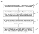
- an embodiment of the present disclosure provides a circuit protection method, which includes:
- the sending end and the receiving end involved in the embodiment of the present disclosure are each internally provided with a wireless transmitting and receiving apparatus, not only are applied to the electric vehicles and the electric bicycles, but also can be applied to the wireless charging process of a terminal.
- the input control switch When it is detected that the sampled voltage value or current value is out of the first threshold range, the input control switch is controlled to be turned off, the input of the voltage or the current of the sending end is stopped, and a notification message is sent to the sending end to inform the sending end to re-send the voltage or the current.
- the receiving end detects the collected voltage value or current value sent by the sending end firstly, and only when it is detected that the voltage value or the current value is in a tolerable range of the receiving end, the receiving end is allowed to receive the voltage value or the current value sent by the sending end by controlling the input control switch to be turned on. Thus, the safety of the voltage or the current received by the receiving end is ensured.
- step that the received voltage or current is converted can specifically include that:
- the method further includes that:
- the first threshold range and the second threshold range can be flexibly set according to practical situations.
- the output control switch before the processed voltage or current is outputted to the battery, it is necessary to detect whether the voltage value or the current value is legal; if YES, the output control switch is controlled to be turned on, and the voltage or the current is outputted to the battery in order to charge the battery; and if NO, the output control switch is controlled to be turned off, and the output is prohibited.
- the safety of the battery is ensured, and the damage probability of the battery is reduced.
- Fig. 2 is a specific implementation flowchart of a circuit protection method according to an embodiment of the present disclosure. The technical solutions of the embodiments of the present disclosure are further described below with reference to Fig. 2 .
- An embodiment of the present disclosure also provides a computer storage medium, and a computer executable instruction is stored in the computer storage medium and is configured for the circuit protection method.
- an embodiment of the present disclosure also provides a circuit protection apparatus, which includes: a sampling unit 41, a first detection unit 42, a control unit 43, a conversion unit 44 and a second detection unit 45, wherein the sampling unit 41 is configured to sample a voltage value or a current value sent by a sending end; the first detection unit 42 is configured to trigger the control unit 43 when it is detected that the voltage value or the current value is in a first pre-set threshold range; the control unit 43 is configured to control a pre-set input control switch to be turned on to enable a voltage or a current of the sending end to be inputted; the conversion unit 44 is configured to convert the received voltage or current; the sampling unit 41 is further configured to sample a voltage value of the processed voltage or a current value of the processed current; the second detection unit 45 is configured to trigger the control unit 43 when it is detected that the processed voltage value or current value is in a second pre-set threshold range; and the control unit 43 is further configured to control
- the control unit 43 when the first detection unit 42 detects that the voltage value or the current value collected by the sampling unit 41 and sent by the sending end is out of the first threshold range, the control unit 43 is triggered; the control unit 43 controls the input control switch to be turned off, and the input of the voltage or the current of the sending end is stopped; and meanwhile, the control unit 43 is further configured to trigger the conversion unit 44 to send a notification message to the sending end so as to inform the sending end to re-send the voltage or the current.
- the conversion unit 44 is configured to perform rectification, voltage dividing/current dividing, and alternating current-direct current conversion on the received voltage or current, and output the processed voltage or current; and here, the conversion unit 44 can output the processed voltage or current to a battery in order to charge the battery.
- the sampling unit 41 is configured to sample the voltage or the current processed by the conversion unit 44 to obtain a processed voltage value or current value, and transmit the processed voltage value or current value to the second detection unit 45;
- the second detection unit 45 is configured to trigger the control unit 43 when it is detected that the processed voltage value or current value is in a second pre-set threshold range;
- the control unit 43 is further configured to control a pre-set output control switch to be turned on, and allow the conversion unit 44 to output the processed voltage or current.
- the second detection unit 45 is further configured to trigger the control unit 43 when it is detected that the processed voltage value or current value is out of the second pre-set threshold range; and the control unit 43 is further configured to control the pre-set output control switch to be turned off, and prohibit the conversion unit 44 from outputting the processed voltage or current.
- the conversion unit 44 re-performs rectification, voltage dividing/current dividing, alternating current-direct current conversion, and other processing on the voltage or the current received by the receiving end, and after the processing is completed, the sampling unit 41 is triggered; and the sampling unit 41 collects the processed voltage value of the voltage or the processed current value of the current, and transmits the collected voltage value or current value to the first detection unit 42, and the first detection unit 42 detects whether the voltage value or the current value is in the first threshold range.
- the first detection unit 42 detects the voltage value or the current value sent by the sending end, only when it is detected that the voltage value or the current value is in a tolerable range of the receiving end, the control unit 43 controls the input control switch to be turned on, so that the voltage or the current sent by the sending end can be allowed to be received. Thus, the safety of the voltage or the current received by the receiving end is ensured.
- the control unit 43 controls the output control switch to be turned on, and triggers the conversion unit 44 to output the legal voltage or current to the battery; and when the second detection unit 42 detects that the processed voltage value or current value is illegal, the control unit 43 controls the output control switch to be turned off, so that the conversion unit 44 cannot output the illegal voltage or current to the battery.
- An embodiment of the present disclosure also provides a charging device, which includes the circuit protection apparatus.
- the sampling unit 41, the first detection unit 42, the control unit 43, the conversion unit 44 and the second detection unit 45 can be each realized by a Central Processing Unit (CPU) or a Digital Signal Processor (DSP) or a Micro Processor Unit (MPU) or a Field Programmable Gate Array (FPGA) and the like; and the CPU, the DSP, the MPU and the FPGA can be built in the charging device, specifically a charging device for an electric vehicle, an electric bicycle or a terminal.
- CPU Central Processing Unit
- DSP Digital Signal Processor
- MPU Micro Processor Unit
- FPGA Field Programmable Gate Array
- the embodiments of the present disclosure can provide a method, a system or a computer program product.
- forms of hardware embodiments, software embodiments or embodiments integrating software and hardware can be adopted in the present disclosure.
- a form of the computer program product implemented on one or more computer available storage media including, but not limited to, a disk memory, an optical memory and the like
- computer available program codes can be adopted in the present disclosure.
- each flow and/or block in the flowcharts and/or the block diagrams and a combination of the flows and/or the blocks in the flowcharts and/or the block diagrams can be realized by computer program instructions.
- These computer program instructions can be provided for a general computer, a dedicated computer, an embedded processor or processors of other programmable data processing devices to generate a machine, so that an apparatus for realizing functions assigned in one or more flows of the flowcharts and/or one or more blocks of the block diagrams is generated via instructions executed by the computers or the processors of the other programmable data processing devices.
- These computer program instructions can also be stored in a computer readable memory capable of guiding the computers or the other programmable data processing devices to work in a specific mode, so that a manufactured product including an instruction apparatus is generated via the instructions stored in the computer readable memory, and the instruction apparatus realizes the functions assigned in one or more flows of the flowcharts and/or one or more blocks of the block diagrams.
- These computer program instructions can also be loaded to the computers or the other programmable data processing devices, so that processing realized by the computers is generated by executing a series of operation steps on the computers or the other programmable devices, and therefore the instructions executed on the computers or the other programmable devices provide a step of realizing the functions assigned in one or more flows of the flowcharts and/or one or more blocks of the block diagrams.
- the embodiments of the present disclosure provide the circuit protection method and apparatus, the charging device and the computer storage medium.
- the method includes that: the voltage or the current sent by the sending end is received, and the received voltage value or current value is sampled; when it is detected that the sampled voltage value or current value is in the first pre-set threshold range, the pre-set input control switch is controlled to be turned on, and the input of the voltage or the current of the sending end is received; the received voltage or current is converted, and the voltage value of the processed voltage or the current value of the processed current is sampled; and when it is detected that the processed voltage value or current value is in the second pre-set threshold range, the pre-set output control switch is controlled to be turned on, and the processed voltage or current is allowed to be outputted.
- the detection of the illegal voltage value or current value can be realized, so that the illegal voltage value or current value cannot be inputted to the battery side.
- the damage probability of the battery is reduced, and the safety of wireless charging is improved.
Landscapes
- Engineering & Computer Science (AREA)
- Power Engineering (AREA)
- Computer Networks & Wireless Communication (AREA)
- Charge And Discharge Circuits For Batteries Or The Like (AREA)
- Protection Of Static Devices (AREA)
Applications Claiming Priority (2)
| Application Number | Priority Date | Filing Date | Title |
|---|---|---|---|
| CN201310452456.7A CN104518534A (zh) | 2013-09-27 | 2013-09-27 | 一种电路保护方法及装置、充电设备 |
| PCT/CN2014/080115 WO2015043241A1 (zh) | 2013-09-27 | 2014-06-17 | 电路保护方法、装置、充电设备及计算机存储介质 |
Publications (2)
| Publication Number | Publication Date |
|---|---|
| EP3051655A1 true EP3051655A1 (de) | 2016-08-03 |
| EP3051655A4 EP3051655A4 (de) | 2016-09-28 |
Family
ID=52741968
Family Applications (1)
| Application Number | Title | Priority Date | Filing Date |
|---|---|---|---|
| EP14847316.8A Withdrawn EP3051655A4 (de) | 2013-09-27 | 2014-06-17 | Schutzschaltungsverfahren und -vorrichtung, ladevorrichtung und computerspeichermedium |
Country Status (5)
| Country | Link |
|---|---|
| US (1) | US10020663B2 (de) |
| EP (1) | EP3051655A4 (de) |
| JP (1) | JP2016536954A (de) |
| CN (1) | CN104518534A (de) |
| WO (1) | WO2015043241A1 (de) |
Cited By (2)
| Publication number | Priority date | Publication date | Assignee | Title |
|---|---|---|---|---|
| CN106505682A (zh) * | 2016-11-30 | 2017-03-15 | 北京新能源汽车股份有限公司 | 一种充电保护电路及电动汽车 |
| WO2018200148A1 (en) * | 2017-04-24 | 2018-11-01 | Qualcomm Incorporated | Wireless power transfer protection |
Families Citing this family (5)
| Publication number | Priority date | Publication date | Assignee | Title |
|---|---|---|---|---|
| CN106100025B (zh) * | 2016-06-24 | 2019-04-19 | 青岛海信移动通信技术股份有限公司 | 一种充电保护电路、充电保护方法及移动终端 |
| US9948401B1 (en) * | 2016-10-04 | 2018-04-17 | Finisar Corporation | Individual DC and AC current shunting in optical receivers |
| CN107300911A (zh) * | 2017-08-15 | 2017-10-27 | 中车唐山机车车辆有限公司 | 故障检测方法、装置及系统 |
| US10333335B2 (en) | 2017-10-27 | 2019-06-25 | Lear Corporation | System and method of electric vehicle wireless charger output protection using zero voltage switching |
| EP3958428B1 (de) * | 2020-06-15 | 2023-01-11 | Contemporary Amperex Technology Co., Limited | Steuervorrichtung, energieumwandlungssystem, energieumwandlungsverfahren und speichermedium |
Family Cites Families (18)
| Publication number | Priority date | Publication date | Assignee | Title |
|---|---|---|---|---|
| US4255789A (en) * | 1978-02-27 | 1981-03-10 | The Bendix Corporation | Microprocessor-based electronic engine control system |
| FR2560721B1 (fr) | 1984-03-01 | 1988-01-15 | Ducellier & Cie | Dispositif temoin de charge d'une batterie de vehicule automobile |
| JP2007520180A (ja) | 2003-10-14 | 2007-07-19 | ブラック アンド デッカー インク | 電池パックの障害状態からの保護を提供するべく適合された二次電池、電動工具、充電器、及び電池パック用の保護方法、保護回路、及び保護装置 |
| US6879133B1 (en) * | 2004-03-26 | 2005-04-12 | Motorola, Inc. | Battery protection circuit |
| US20050242778A1 (en) * | 2004-04-30 | 2005-11-03 | Yen-Hsi Lin | Controlling circuit for long-time battery retention |
| CN1979992A (zh) * | 2005-12-07 | 2007-06-13 | 比亚迪股份有限公司 | 一种二次电池组的充放电保护电路 |
| CN100589305C (zh) * | 2006-09-29 | 2010-02-10 | 美国凹凸微系有限公司 | 用于电池组保护的涓流放电方法 |
| CN101222146A (zh) | 2007-01-12 | 2008-07-16 | 曹先国 | 电池充电器集成电路 |
| JP4849171B2 (ja) | 2007-09-10 | 2012-01-11 | トヨタ自動車株式会社 | 充電システムの異常判定装置および異常判定方法 |
| CN201113411Y (zh) * | 2007-09-21 | 2008-09-10 | 深圳市比克电池有限公司 | 电池保护装置 |
| CN102255342B (zh) * | 2010-05-18 | 2013-07-10 | 中国兵器工业第二〇五研究所 | 装甲车辆用电源管理器 |
| US8943335B2 (en) * | 2010-12-22 | 2015-01-27 | Atmel Corporation | Battery management and protection system using a module in a sleepwalking mode to monitor operational characteristics of a battery |
| JP5315369B2 (ja) | 2011-03-01 | 2013-10-16 | 株式会社日立製作所 | リチウム二次電池の異常充電状態検出装置及び検査方法 |
| US9444247B2 (en) * | 2011-05-17 | 2016-09-13 | Samsung Electronics Co., Ltd. | Apparatus and method of protecting power receiver of wireless power transmission system |
| WO2013015207A1 (ja) | 2011-07-28 | 2013-01-31 | 三洋電機株式会社 | 電池パック及び電池パックの充電方法 |
| CN202737569U (zh) * | 2012-08-16 | 2013-02-13 | 佛山市柏克新能科技股份有限公司 | 一种单相互动式eps电源 |
| CN202737561U (zh) | 2012-08-16 | 2013-02-13 | 佛山市柏克新能科技股份有限公司 | 小型三相互动式ups电源 |
| CN203218872U (zh) | 2013-04-03 | 2013-09-25 | 天津市尚洲科技有限公司 | 基于单片机的低功耗镍氢电池保护电路 |
-
2013
- 2013-09-27 CN CN201310452456.7A patent/CN104518534A/zh active Pending
-
2014
- 2014-06-17 JP JP2016516954A patent/JP2016536954A/ja active Pending
- 2014-06-17 US US15/024,913 patent/US10020663B2/en active Active
- 2014-06-17 WO PCT/CN2014/080115 patent/WO2015043241A1/zh not_active Ceased
- 2014-06-17 EP EP14847316.8A patent/EP3051655A4/de not_active Withdrawn
Cited By (3)
| Publication number | Priority date | Publication date | Assignee | Title |
|---|---|---|---|---|
| CN106505682A (zh) * | 2016-11-30 | 2017-03-15 | 北京新能源汽车股份有限公司 | 一种充电保护电路及电动汽车 |
| CN106505682B (zh) * | 2016-11-30 | 2019-08-27 | 北京新能源汽车股份有限公司 | 一种充电保护电路及电动汽车 |
| WO2018200148A1 (en) * | 2017-04-24 | 2018-11-01 | Qualcomm Incorporated | Wireless power transfer protection |
Also Published As
| Publication number | Publication date |
|---|---|
| US10020663B2 (en) | 2018-07-10 |
| EP3051655A4 (de) | 2016-09-28 |
| WO2015043241A1 (zh) | 2015-04-02 |
| CN104518534A (zh) | 2015-04-15 |
| JP2016536954A (ja) | 2016-11-24 |
| US20160218532A1 (en) | 2016-07-28 |
Similar Documents
| Publication | Publication Date | Title |
|---|---|---|
| US10020663B2 (en) | Circuit protection method and apparatus, charging device and computer storage medium | |
| CN104993611B (zh) | 一种无线充电的鉴权方法和装置 | |
| CN109314396A (zh) | 无线充电系统、装置、方法及待充电设备 | |
| CN104037920B (zh) | 一种铅酸电池智能充电控制系统 | |
| MY173120A (en) | Power adapter, terminal, and method for handling impedance anomaly in charging loop | |
| WO2014022874A3 (de) | Ladeanschlussvorrichtung für elektrofahrzeuge | |
| EP2728706A2 (de) | Verfahren und Vorrichtung zur drahtlosen Stromübertragung | |
| JP6607669B2 (ja) | ワイヤレス充電装置及びその充電方法 | |
| EP4306976A3 (de) | Detektionsschaltung, verfahren und vorrichtung | |
| CN105830304B (zh) | 充电器 | |
| CN104201747A (zh) | 一种电动汽车慢充断路故障处理方法及装置 | |
| CN104518250A (zh) | 一种汽车无线充电方法和装置 | |
| KR102351067B1 (ko) | 전기 자동차용 배터리 전원 공급 장치 및 방법 | |
| CN104426186A (zh) | 一种充电控制方法及电子设备 | |
| JP2018511160A5 (de) | ||
| CN204941702U (zh) | 燃气轮机保护装置 | |
| US9151623B2 (en) | Method and apparatus for controlling an electrical device and a wireless charging device | |
| CN107046309A (zh) | 一种自动调节充电电流的充电方法和装置 | |
| CN105182812A (zh) | 一种电动汽车充电站的网络监控系统 | |
| CN115042671A (zh) | 车辆电池加热方法、装置、介质和车辆 | |
| US9678238B2 (en) | Intelligent train wheel sensor | |
| US9647482B2 (en) | Smart wireless charger | |
| CN107825979A (zh) | 车辆充电方法、装置和系统 | |
| WO2017088280A1 (zh) | 一种智能数据线安全充电的方法 | |
| CN102929378B (zh) | 过电流保护系统及其方法 |
Legal Events
| Date | Code | Title | Description |
|---|---|---|---|
| PUAI | Public reference made under article 153(3) epc to a published international application that has entered the european phase |
Free format text: ORIGINAL CODE: 0009012 |
|
| 17P | Request for examination filed |
Effective date: 20160405 |
|
| AK | Designated contracting states |
Kind code of ref document: A1 Designated state(s): AL AT BE BG CH CY CZ DE DK EE ES FI FR GB GR HR HU IE IS IT LI LT LU LV MC MK MT NL NO PL PT RO RS SE SI SK SM TR |
|
| AX | Request for extension of the european patent |
Extension state: BA ME |
|
| A4 | Supplementary search report drawn up and despatched |
Effective date: 20160830 |
|
| RIC1 | Information provided on ipc code assigned before grant |
Ipc: H02J 7/00 20060101AFI20160824BHEP Ipc: H02J 50/10 20160101ALI20160824BHEP |
|
| DAX | Request for extension of the european patent (deleted) | ||
| STAA | Information on the status of an ep patent application or granted ep patent |
Free format text: STATUS: EXAMINATION IS IN PROGRESS |
|
| 17Q | First examination report despatched |
Effective date: 20180806 |
|
| STAA | Information on the status of an ep patent application or granted ep patent |
Free format text: STATUS: THE APPLICATION HAS BEEN WITHDRAWN |
|
| 18W | Application withdrawn |
Effective date: 20180917 |