EP3050442A1 - Verfahren und vorrichtung zum herstellen von filtern der tabak verarbeitenden industrie - Google Patents
Verfahren und vorrichtung zum herstellen von filtern der tabak verarbeitenden industrie Download PDFInfo
- Publication number
- EP3050442A1 EP3050442A1 EP16150918.7A EP16150918A EP3050442A1 EP 3050442 A1 EP3050442 A1 EP 3050442A1 EP 16150918 A EP16150918 A EP 16150918A EP 3050442 A1 EP3050442 A1 EP 3050442A1
- Authority
- EP
- European Patent Office
- Prior art keywords
- additive
- introduction
- conveying
- introduction material
- filter
- Prior art date
- Legal status (The legal status is an assumption and is not a legal conclusion. Google has not performed a legal analysis and makes no representation as to the accuracy of the status listed.)
- Granted
Links
Images

Classifications
-
- A—HUMAN NECESSITIES
- A24—TOBACCO; CIGARS; CIGARETTES; SIMULATED SMOKING DEVICES; SMOKERS' REQUISITES
- A24D—CIGARS; CIGARETTES; TOBACCO SMOKE FILTERS; MOUTHPIECES OF CIGARS OR CIGARETTES; MANUFACTURE OF TOBACCO SMOKE FILTERS OR MOUTHPIECES
- A24D3/00—Tobacco smoke filters, e.g. filter tips or filtering inserts; Filters specially adapted for simulated smoking devices; Mouthpieces of cigars or cigarettes
- A24D3/02—Manufacture of tobacco smoke filters
- A24D3/0204—Preliminary operations before the filter rod forming process, e.g. crimping, blooming
- A24D3/0212—Applying additives to filter materials
-
- A—HUMAN NECESSITIES
- A24—TOBACCO; CIGARS; CIGARETTES; SIMULATED SMOKING DEVICES; SMOKERS' REQUISITES
- A24D—CIGARS; CIGARETTES; TOBACCO SMOKE FILTERS; MOUTHPIECES OF CIGARS OR CIGARETTES; MANUFACTURE OF TOBACCO SMOKE FILTERS OR MOUTHPIECES
- A24D3/00—Tobacco smoke filters, e.g. filter tips or filtering inserts; Filters specially adapted for simulated smoking devices; Mouthpieces of cigars or cigarettes
- A24D3/02—Manufacture of tobacco smoke filters
- A24D3/0204—Preliminary operations before the filter rod forming process, e.g. crimping, blooming
- A24D3/0212—Applying additives to filter materials
- A24D3/022—Applying additives to filter materials with liquid additives, e.g. application of plasticisers
Definitions
- the invention further relates to an apparatus for producing filters of the tobacco processing industry with a filter material delivery device, wherein the filter material delivery device a Having guide portion through which a filter material is feasible or guided.
- an introduction material which absorbs the additive and is elongate and continuous, is usually introduced into the filter material and previously impregnated or wetted with an additive, such as a flavor.
- EP 2 178 403 B1 provides for this a channel through which an additive is introduced and through which a solid support is drawn, with continuous immersion in the additive, to allow the additive to be absorbed by the wearer.
- EP 2 046 154 B1 provides to introduce into a filter material in the production of the filter strand, a non-Flavourstoff filament material and to supply a flavor agent.
- EP 2 123 180 A1 discloses a device for introducing additives into a provided for producing a smoking article and already round-shaped strand with a guide portion through which the strand is feasible in the transport direction, and an acting in the guide portion feed device for downstream feed of additives in the strand located in the guide section wherein the feeding device is designed such that it delivers the additive or the additives in at least two beams directed at an angle to one another.
- the additive By conveying the additive and the introduction material in a common conveying member, it is possible to selectively apply the additive to the introduction material.
- the application of the additive at an application speed which is essentially the conveying speed of the introduction material corresponds, the additive can penetrate better in the introduction material, whereby a better saturation of the introduction material is made possible with the additive.
- the application speed is preferably the speed or the speed component which is present in the conveying direction of the introduction material. Preferably, this is between 90% to 130% of the conveying speed of the introduction material, in particular between 95% and 120% of the conveying speed of the introduction material, in particular preferably between 100% and 110% of the conveying speed of the introduction material.
- the conveying speed of the introduction material preferably corresponds to the conveying speed of the filter material.
- the application speed is preferably controlled or regulated as a function of the conveying speed of the introduction material.
- a section-wise parallel conveying is provided in the separate conveying of the additive and the introduction material.
- a common conveyor organ can be realized, which is very compact, i. building with a small cross-section is.
- the application of the additive takes place on the introduction material outside of the common conveying member.
- the entire additive reaches the introduction material and any additive which does not penetrate into or attaches to the introduction material passes into the filter material which is arranged around the introduction material. This allows a precise amount of a Additive are specified in the filter strand to be manufactured.
- the application of the additive thus takes place preferably when introducing the introduction material into the filter material.
- the additive prior to application to the introduction material is conveyed completely separated from the introduction material in the common conveying member.
- the separate promotion is provided at least until the output of the common conveying member.
- the filter strand is formed downstream of the application or when the additive is applied to the introduction material in the format device.
- the filter strand is in this case usually formed so that the filter material is introduced into an inlet nozzle of a format device.
- the introduction material is preferably introduced centrally into the filter material, and where the introduction material is introduced into the filter material, the additive is applied to the introduction material.
- a wrapping material strip is usually wrapped around the filter material, especially in the format device, and a seam of the wrapping material strip is sealed with an adhesive.
- a round in cross-section filter strand is formed.
- it can also be formed an oval shaped filter strand.
- the applied amount of the additive is controlled.
- additive delivery lines in the common delivery member provided, wherein a predetermined number of additive delivery lines depending on the amount of additive to be applied promote additive.
- 10 additive delivery lines can be provided and, depending on the amount of additive to be applied, more or fewer delivery lines for the additive to be delivered can be opened or closed.
- the additive delivery lines are arranged so that always opposing additive delivery lines are opened.
- additive is always applied from opposite sides to the introduction material.
- some additive delivery lines have a different cross section than other additive delivery lines, with the opposed additive delivery lines preferably having the same cross section.
- the additive is conveyed through at least one nozzle for application to the introduction material, wherein in particular an additive jet is produced, which is conveyed at an angle of 10 ° to 60 °, in particular 20 ° to 50 °, to the introduction material onto the introduction material.
- an additive jet is produced, which is conveyed at an angle of 10 ° to 60 °, in particular 20 ° to 50 °, to the introduction material onto the introduction material.
- a device for the production of filters of the tobacco processing industry with a filter material conveying device, wherein the filter material conveying device has a guide portion through which a filter material is feasible or guided, wherein a introduced into the guide portion common conveyor member for introducing an elongated and continuous Einbringmaterials and an additive is provided, wherein the additive downstream of the output of the conveying member can be applied to the introduction material or applied.
- the additive downstream of the output of the conveying member is applied to the Einbringmaterial or is applied, a very accurate metering of the additive is possible.
- an additive conveyor is provided, by means of which the additive can be applied or applied to the introduction material at an application speed which substantially corresponds to or is greater than the conveying speed of the introduction material.
- the additive conveyor preferably includes a controller or controller to control or control the rate of application.
- the control device or the control device a Einbringmaterial stir effetica, which results from the conveying speed of the filter material, and substantially, for example, the conveying speed of a format strip in the format device, supplied to adjust a corresponding additive conveying speed via the control device or control device.
- a sensor for measuring the speed of the additive is provided.
- the viscosity of the additive which is known via a temperature measurement and knowledge of the additive itself or the behavior of the viscosity of the additive over the temperature, the diameter of the delivery line and the pressure that the pump provides, the speed of the additive.
- the additive conveyor may have a pump which introduces additive from an additive supply into one or more delivery lines of the common delivery member and supplies it with a corresponding pressure, so that the additive is ejected at the exit of the common delivery member at a corresponding speed becomes.
- the common conveying member is designed to promote both the introduction material and the additive.
- the common conveying member is formed as a tube having continuous conveying lines for the introduction material and the additive.
- the common conveying member for the introduction material and the additive completely separate conveying channels, so that the introduction material and the additive in the common conveying member are conveyed, so that only at the output of the common conveying member, the additive is applied to the Einbringmaterial or applied.
- the tube has, in particular, a central delivery line for the introduction material and, outside this delivery line, corresponding additive delivery lines or delivery lines for the additive.
- At least two delivery lines for the additive are preferably provided around a central delivery line.
- a plurality, preferably more than three, delivery lines are provided, wherein in particular an even number of delivery lines is provided.
- the delivery lines for the additive may also be provided for various additives.
- different sizes of the delivery line can be provided in order to better adjust the dosage of the additive can.
- the delivery lines for the additive or the additives are arranged symmetrically about the central delivery line.
- on the output side of the delivery lines for the additive are provided at a predeterminable angle to the Einbringmaterial aligned nozzles. This serves to selectively apply additive to the introduction material.
- the nozzles are aligned in such a way that the additive jet, which is directed onto the introduction material, hits the introduction material at the predeterminable angle.
- the predeterminable angle is preferably an angle between 20 ° and 50 °.
- the number of conveying lines leading the additive is preferably designed to be switchable or switchable.
- an additive or various additives may be used.
- the additive conveyor may be designed such that, in the case of various additives, the pump or pumping device is simultaneously assigned the additives to the respective delivery lines for additives from different additive supplies.
- the filter material is preferably a filter tow.
- the additive is a flavor.
- the introduction material is a yarn or a thread.
- the invention is characterized in that the introduction material and the additive is transported separately in a multi-nozzle tube or tube.
- This redesigned tube which may also be referred to as a common conveyor, is used in place of a commonly used burster tube.
- the introduction material is guided in a central bore of the tube.
- the additive is passed through several small, circumferentially distributed channels or additive delivery lines.
- the additive is applied in at least two opposing additive delivery lines.
- the feeding of the additive into the channels takes place outside a format device of a filter rod machine.
- the application of the additive to the introduction material takes place at the exit or after the exit from the tube.
- the invention has the advantage that the additive is applied to the introduction material under high pressure, resulting in improved uptake of the additive by the introduction material.
- the greatest possible accuracy of the additive application quantity is achieved, since the supply and the application of the additive are specifically intended for strand forming at the last possible time.
- Fig. 1 schematically shows a part of a formatting device 7 a strand machine of the tobacco processing industry.
- a filter material 5 for example a filter tow material, is introduced into the format device 7 after appropriate preparation in the direction of movement B by a funnel device 6.
- the format device 7 has a first format upper part 7a, which comprises the funnel device 6, and a second format upper part 7b, which comprises, for example, an inlet finger 8.
- the inlet finger 8 presses the introduced filter material 5 on a not shown format tape, which is guided in the direction of movement B by the format device 7.
- a wrapping material strip is arranged, which is wound around a usually round shaped filter material 5 in the formatting device 7, wherein at the end of the wrapping material strip is provided at an adhesive seam with adhesive and the wrapping material strip is so closed. It then joins a Nahtplätte to a Setting the adhesive, such as glue, by heating or cooling to accelerate. Finally, the filter material strip produced in this way is cut to length in accordance with specifiable long filter rods.
- a tube 1 for example a tube, which is guided through the filter material 5 and whose outlet 10 is arranged centrally in the filter material 5, guides a thread 1 via a common conveying member 2, which is provided with an additive 19.
- the additive 19, for example a flavor is supplied from an additive reservoir 12 via a line 14 to a pump 11 and introduced via a line 14 from the pump 11 into the common conveying member 2.
- the thread 1 and the additive 19 is guided separately, parallel to the output 10 of the common conveyor member 2.
- the common conveyor member 2 is explained in more detail in the following figures.
- control device 13 which controls the pump 11, for example via an electrical line 15.
- the control device 13 can preferably also control valves which control the inflow of additives 19 in additive lines in the common conveying member 2.
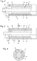
- Fig. 2 shows in a schematic representation, in a partial sectional view, the common conveyor member 2. It is shown a central bore or a Einbringmaterialkanal 16, in which the introduction material 1, for example a thread, is conveyed in the direction of movement B. In addition, additive delivery lines 17 are provided, in which an additive 19 is conveyed, and also in the direction of movement B. At the output of the additive channels or
- Delivery lines 17 each have a nozzle 18 is shown, which is aligned so that it applies the additive 19 in an additive beam 20 at an angle ⁇ on the thread 1.
- the angle ⁇ is 27 °.
- the application angle ⁇ is greater, ie the nozzles 18 are aligned so that a different application angle ⁇ is formed.
- the angle here is 47 °, for example. It can be seen that the place of application, which is represented by the dotted line, in the direction of movement B or in the conveying direction of the thread 1 downstream of the output 10 of the common conveying member 2 is provided. In addition, it can be seen that the additive 19 and the thread 1 are conveyed separately in the common conveying member.
- Fig. 4 schematically shows a sectional view along the section AA Fig. 3 ,
- the additive channels 17 are arranged.
- more or fewer additive channels 17 are to be used.
- These can be switched on or off, for example, by valves.
- opposing additive channels 17 are always used to apply additive 19 to the yarn 1.
- the cross-section of the additive channels 17 may be the same size or even be partially different. It may, for example, be provided to provide two additive channels 17 with a diameter of 0.11 mm and the other additive channels 17 with a cross section of 0.2 to 0.4 mm, in particular 0.35 mm.
- the distance of the additive channels 17 to the outer circumference of the common conveying member 2 is preferably one millimeter.
- the distance to the Einbringmaterialkanal 16 is preferably also at one millimeter.
- the Einbringmaterialkanal 16 preferably has a diameter of three times the thread diameter, for example, the thread diameter is between 0.5 and 2 mm or preferably 0.8 to 1.2 mm. With a thread diameter of 1.2 mm, this would result in a diameter of the introduction material channel 16 of 3.6 mm.
- the larger Einbringmaterialkanal canmesser compared to the diameter of the thread results from the fact that possibly the thread can knot and this should not lead to a standstill of the machines.
Landscapes
- Cigarettes, Filters, And Manufacturing Of Filters (AREA)
Abstract
Description
- Die Erfindung betrifft ein Verfahren zum Herstellen von Filtern der Tabak verarbeitenden Industrie mit den folgenden Verfahrensschritten:
- Kontinuierliches Fördern eines Filtermaterials von einem Filtermaterialvorrat in eine Formatvorrichtung zum Ausbilden eines kontinuierlichen Filterstrangs,
- Einbringen eines ein flüssiges Additiv aufnehmenden, länglichen und kontinuierlichen Einbringmaterials, insbesondere eines Fadens, in das Filtermaterial beim Fördern des Filtermaterials.
- Die Erfindung betrifft ferner eine Vorrichtung zur Herstellung von Filtern der Tabak verarbeitenden Industrie mit einer Filtermaterialfördervorrichtung, wobei die Filtermaterialfördervorrichtung einen Führungsabschnitt aufweist, durch den ein Filtermaterial führbar oder geführt ist.
- Bei der Herstellung von Filtern der Tabak verarbeitenden Industrie ist es für einige Produkte gewünscht, Additive in das Filtermaterial einzubringen. Hierzu wird üblicherweise ein Einbringmaterial, das das Additiv aufnimmt und länglich und kontinuierlich ausgebildet ist, in das Filtermaterial eingebracht und vorher mit einem Additiv, wie beispielsweise einem Flavour, durchtränkt bzw. benetzt.
-
EP 2 178 403 B1 sieht hierzu einen Kanal vor, durch den ein Zusatzstoff eingeleitet wird und durch den ein fester Träger hindurchgezogen wird, und zwar unter kontinuierlichem Eintauchen in den Zusatzstoff, um den Zusatzstoff durch den Träger aufnehmen zu lassen. -
EP 2 046 154 B1 sieht vor, in ein Filtermaterial bei der Herstellung des Filterstrangs ein Nicht-Flavourstoff-Filamentmaterial einzuführen und diesem ein Flavour-Agens zuzuführen. -
EP 2 123 180 A1 offenbart eine Vorrichtung zum Einbringen von Additiven in einen zur Herstellung eines Rauchartikels vorgesehenen und bereits rundgeformten Strang mit einem Führungsabschnitt, durch den der Strang in Transportrichtung führbar ist, und einer in den Führungsabschnitt wirkenden Einspeiseeinrichtung zur stromabwärts gerichteten Einspeisung von Additiven in den im Führungsabschnitt befindlichen Strang, wobei die Einspeiseeinrichtung derart ausgebildet ist, dass sie das Additiv oder die Additive in mindestens zwei winklig zueinander gerichteten Strahlen abgibt. - Es ist Aufgabe der vorliegenden Erfindung, eine bessere und genauere Befüllung eines Filterstrangs mit einem Additiv zu ermöglichen.
- Gelöst wird diese Aufgabe durch ein Verfahren zum Herstellen von Filtern der Tabak verarbeitenden Industrie mit den folgenden Verfahrensschritten:
- Kontinuierliches Fördern eines Filtermaterials von einem Filtermaterialvorrat in eine Formatvorrichtung zum Ausbilden eines kontinuierlichen Filterstrangs,
- Einbringen eines ein flüssiges Additiv aufnehmenden, länglichen und kontinuierlichen Einbringmaterials, insbesondere eines Fadens, in das Filtermaterial beim Fördern des Filtermaterials,
- Auftragen des Additivs auf das Einbringmaterial beim Einbringen des Einbringmaterials in das Filtermaterial, wobei
- das Additiv vor dem Auftragen auf das Einbringmaterial wenigstens abschnittsweise getrennt zu dem Einbringmaterial in einem gemeinsamen Förderorgan gefördert wird und/oder wobei das Additiv mit einer Auftragsgeschwindigkeit auf das Einbringmaterial aufgetragen wird, die im Wesentlichen der Fördergeschwindigkeit des Einbringmaterials entspricht oder größer ist.
- Durch Fördern des Additivs und des Einbringmaterials in einem gemeinsamen Förderorgan ist es möglich, gezielt das Additiv auf das Einbringmaterial aufzutragen. Zudem ist es erfindungsgemäß so, dass das Auftragen des Additivs mit einer Auftragsgeschwindigkeit, die im Wesentlichen der Fördergeschwindigkeit des Einbringmaterials entspricht, das Additiv besser in das Einbringmaterial eindringen kann, wodurch eine bessere Durchsättigung des Einbringmaterials mit dem Additiv ermöglicht ist. Bei der Auftragsgeschwindigkeit handelt es sich vorzugsweise um die Geschwindigkeit bzw. die Geschwindigkeitskomponente, die in Förderrichtung des Einbringmaterials vorliegt. Vorzugsweise ist diese zwischen 90% bis 130% der Fördergeschwindigkeit des Einbringmaterials, insbesondere zwischen 95% und 120% der Fördergeschwindigkeit des Einbringmaterials, insbesondere vorzugsweise zwischen 100% und 110% der Fördergeschwindigkeit des Einbringmaterials.
- Vorzugsweise entspricht die Fördergeschwindigkeit des Einbringmaterials der Fördergeschwindigkeit des Filtermaterials.
- Vorzugsweise wird die Auftragsgeschwindigkeit abhängig von der Fördergeschwindigkeit des Einbringmaterials gesteuert oder geregelt. Hierdurch wird bei jedweder Fördergeschwindigkeit des Fördermaterials eine effiziente Beladung des Einbringmaterials mit einem Additiv ermöglicht.
- Vorzugsweise ist beim getrennten Fördern des Additivs und des Einbringmaterials ein abschnittsweises paralleles Fördern vorgesehen. Hierdurch kann ein gemeinsames Förderorgan realisiert sein, das sehr kleinbauend, d.h. mit einem geringen Querschnitt bauend, ist.
- Vorzugsweise geschieht das Auftragen des Additivs auf das Einbringmaterial außerhalb des gemeinsamen Förderorgans. Hierdurch gelangt das gesamte Additiv auf das Einbringmaterial und etwaiges nicht in das Einbringmaterial eindringende bzw. an diesem anhaftende Additiv gelangt in das Filtermaterial, das um das Einbringmaterial herum angeordnet ist. Hierdurch kann eine genaue Menge eines Additivs in dem zu fertigenden Filterstrang vorgegeben werden. Das Auftragen des Additivs geschieht somit vorzugsweise beim Einbringen des Einbringmaterials in das Filtermaterial.
- Vorzugsweise wird das Additiv vor dem Auftragen auf das Einbringmaterial vollständig getrennt zu dem Einbringmaterial in dem gemeinsamen Förderorgan gefördert. Vorzugsweise ist die getrennte Förderung zumindest bis zum Ausgang des gemeinsamen Förderorgans vorgesehen.
- Vorzugsweise wird stromabwärts des Auftragens oder beim Auftragen des Additivs auf das Einbringmaterial in der Formatvorrichtung der Filterstrang gebildet. Der Filterstrang wird hierbei üblicherweise so gebildet, dass das Filtermaterial in eine Einlaufdüse einer Formatvorrichtung eingebracht wird. In diesem Einlaufbereich bzw. in einem Bereich, in dem ein Einlauffinger einer Formatvorrichtung vorliegt, wird das Einbringmaterial vorzugsweise mittig in das Filtermaterial eingebracht, und dort, wo das Einbringmaterial in das Filtermaterial eingebracht wird, wird das Additiv auf das Einbringmaterial aufgetragen.
- Danach wird insbesondere in der Formatvorrichtung üblicherweise ein Umhüllungsmaterialstreifen um das Filtermaterial gewickelt und eine Naht des Umhüllungsmaterialstreifens mit einem Klebstoff verschlossen. Hierdurch wird ein im Querschnitt runder Filterstrang gebildet. Es kann allerdings auch ein oval geformter Filterstrang gebildet werden.
- Vorzugsweise wird die aufgetragene Menge des Additivs gesteuert.
- Vorzugsweise sind zum Steuern der aufgetragenen Menge des Additivs mehrere Additivförderleitungen in dem gemeinsamen Förderorgan vorgesehen, wobei eine vorgebbare Anzahl der Additivförderleitungen in Abhängigkeit der aufzutragenden Menge des Additivs Additiv fördern. Hierbei können beispielsweise 10 Additivförderleitungen vorgesehen sein und je nach Menge des aufzutragenden Additivs können mehr oder weniger Förderleitungen für zu förderndes Additiv geöffnet oder verschlossen sein.
- Vorzugsweise sind die Additivförderleitungen so angeordnet, dass immer gegenüberliegende Additivförderleitungen geöffnet sind. Damit wird Additiv immer von entgegengesetzten Seiten auf das Einbringmaterial aufgetragen. Vorzugsweise haben einige Additivförderleitungen einen anderen Querschnitt als andere Additivförderleitungen, wobei die gegenüberliegenden Additivförderleitungen vorzugsweise den gleichen Querschnitt aufweisen.
- Vorzugsweise wird das Additiv durch wenigstens eine Düse zum Auftragen auf das Einbringmaterial gefördert, wobei insbesondere ein Additivstrahl erzeugt wird, der in einem Winkel von 10° bis 60°, insbesondere 20° bis 50°, zu dem Einbringmaterial auf das Einbringmaterial gefördert wird. Hierdurch kann der Treffpunkt des Additivs auf das Einbringmaterial in Förderrichtung stromabwärts des Ausgangs des gemeinsamen Förderorgans genau eingestellt werden.
- Die Aufgabe wir ferner gelöst durch eine Vorrichtung zur Herstellung von Filtern der Tabak verarbeitenden Industrie mit einer Filtermaterialfördervorrichtung, wobei die Filtermaterialfördervorrichtung einen Führungsabschnitt aufweist, durch den ein Filtermaterial führbar oder geführt ist, wobei ein in den Führungsabschnitt eingebrachtes gemeinsames Förderorgan zum Einbringen eines länglichen und kontinuierlichen Einbringmaterials und eines Additivs vorgesehen ist, wobei das Additiv stromabwärts des Ausgangs des Förderorgans auf das Einbringmaterial auftragbar ist oder aufgetragen wird. Dadurch, dass das Additiv stromabwärts des Ausgangs des Förderorgans auf das Einbringmaterial auftragbar ist oder aufgetragen wird, ist eine sehr genaue Dosierung des Additivs möglich.
- Vorzugsweise ist ein Additivförderer vorgesehen, mittels dessen das Additiv mit einer Auftragsgeschwindigkeit auf das Einbringmaterial auftragbar ist oder aufgetragen wird, die im Wesentlichen der Fördergeschwindigkeit des Einbringmaterials entspricht oder größer ist. Der Additivförderer weist vorzugsweise eine Steuervorrichtung oder eine Regelvorrichtung auf, um die Auftragsgeschwindigkeit zu steuern oder zu regeln. Hierzu wird der Steuervorrichtung oder der Regelvorrichtung eine Einbringmaterialfördergeschwindigkeit, die sich aus der Fördergeschwindigkeit des Filtermaterials ergibt, und im Wesentlichen beispielsweise der Fördergeschwindigkeit eines Formatbandes in der Formatvorrichtung entspricht, zugeführt, um eine entsprechende Additivfördergeschwindigkeit über die Steuervorrichtung oder Regelvorrichtung einzustellen.
- Vorzugsweise ist ein Sensor zur Messung der Geschwindigkeit des Additivs vorgesehen. Alternativ kann über die Viskosität des Additivs, die über eine Temperaturmessung und in Kenntnis des Additivs an sich bzw. des Verhaltens der Viskosität des Additivs über die Temperatur bekannt ist, den Durchmesser der Förderleitung und den Druck, den die Pumpe zur Verfügung stellt, die Geschwindigkeit des Additivs bestimmt werden.
- Der Additivförderer kann eine Pumpe aufweisen, die aus einem Additivvorrat Additiv in eine oder mehrere Förderleitungen des gemeinsamen Förderorgans einbringt und mit einem entsprechenden Druck versorgt, so dass das Additiv am Ausgang des gemeinsamen Förderorgans mit einer entsprechenden Geschwindigkeit ausgespritzt wird.
- Vorzugsweise ist das gemeinsame Förderorgan ausgebildet, sowohl das Einbringmaterial als auch das Additiv zu fördern. Vorzugsweise ist das gemeinsame Förderorgan als Rohr ausgebildet, das durchgängige Förderleitungen für das Einbringmaterial und das Additiv aufweist.
- Vorzugsweise weist das gemeinsame Förderorgan für das Einbringmaterial und das Additiv vollständig getrennte Förderkanäle auf, so dass das Einbringmaterial und das Additiv in dem gemeinsamen Förderorgan förderbar sind, so dass erst am Ausgang des gemeinsamen Förderorgans das Additiv auf das Einbringmaterial auftragbar ist oder aufgetragen wird.
- Das Rohr weist insbesondere eine mittige Förderleitung für das Einbringmaterial auf und außen um diese Förderleitung herum entsprechende Additivförderleitungen bzw. Förderleitungen für das Additiv.
- Vorzugsweise sind um eine zentrale Förderleitung herum wenigstens zwei Förderleitungen für das Additiv vorgesehen.
- Für das Additiv sind, insbesondere mehrere, vorzugsweise mehr als drei, Förderleitungen vorgesehen, wobei insbesondere eine gerade Anzahl von Förderleitungen vorgesehen ist. Die Förderleitungen für das Additiv können auch für verschiedene Additive vorgesehen sein. Zudem können verschiedene Größen der Förderleitung vorgesehen sein, um die Dosierung des Additivs besser einstellen zu können.
- Vorzugsweise sind die Förderleitungen für das Additiv oder die Additive symmetrisch um die zentrale Förderleitung angeordnet. Vorzugsweise sind ausgangsseitig der Förderleitungen für das Additiv in einem vorgebbaren Winkel zu dem Einbringmaterial ausgerichtete Düsen vorgesehen. Dies dient dazu, ganz gezielt Additiv auf das Einbringmaterial aufzutragen. Die Düsen sind hierbei so ausgerichtet, dass der Additivstrahl, der auf das Einbringmaterial gerichtet ist, mit dem vorgebbaren Winkel auf das Einbringmaterial trifft. Bei dem vorgebbaren Winkel handelt es sich vorzugsweise um einen Winkel zwischen 20° und 50°.
- Vorzugsweise ist die Anzahl der das Additiv führenden Förderleitungen zuschaltbar oder abschaltbar ausgestaltet.
- Vorzugsweise können ein Additiv oder verschiedene Additive verwendet werden. Der Additivförderer kann so ausgestaltet sein, dass bei verschiedenen Additiven die Pumpe bzw. Pumpvorrichtung gleichzeitig aus verschiedenen Additivvorräten die Additive den jeweiligen Förderleitungen für Additive zugeordnet werden.
- Das Filtermaterial ist vorzugsweise ein Filtertow. Vorzugsweise ist das Additiv ein Flavour. Ferner vorzugsweise ist das Einbringmaterial ein Garn oder ein Faden.
- Die Erfindung zeichnet sich dadurch aus, dass das Einbringmaterial und das Additiv getrennt in einem mehrdüsigen Rohr bzw. Röhrchen transportiert wird. Dieses neu gestaltete Rohr, das auch als gemeinsames Förderorgan bezeichnet werden kann, wird anstelle eines üblicherweise verwendeten Einlegeröhrchens verwendet. Hierbei wird das Einbringmaterial in einer mittleren Bohrung des Rohres geführt. Das Additiv wird durch mehrere kleine, über den Umfang verteilte Kanäle bzw. Additivförderleitungen geleitet. Hierbei wird das Additiv in wenigstens zwei sich gegenüberliegenden Additivförderleitungen appliziert. Je mehr Additiv auf das Einbringmaterial aufgetragen werden soll, umso mehr Kanäle werden hinzugeschaltet. Es können beispielsweise zwei, vier, sechs, acht, zehn oder zwölf Kanäle zugeschaltet werden. Die Zuführung des Additivs in die Kanäle erfolgt außerhalb einer Formatvorrichtung einer Filterstrangmaschine.
- Das Auftragen des Additivs auf das Einbringmaterial findet am Austritt oder nach dem Austritt aus dem Rohr statt.
- Die Erfindung hat den Vorteil, dass das Additiv mit hohem Druck auf das Einbringmaterial aufgetragen wird, was zu einer verbesserten Aufnahme des Additivs durch das Einbringmaterial führt. Es wird eine größtmögliche Genauigkeit der Additivauftragsmenge erreicht, da gezielt die Zuführung sowie die Applikation des Additivs zum letztmöglichen Zeitpunkt bei der Strangformung vorgesehen ist.
- Weitere Merkmale der Erfindung werden aus der Beschreibung erfindungsgemäßer Ausführungsformen zusammen mit den Ansprüchen und den beigefügten Zeichnungen ersichtlich. Erfindungsgemäße Ausführungsformen können einzelne Merkmale oder eine Kombination mehrerer Merkmale erfüllen.
- Die Erfindung wird nachstehend ohne Beschränkung des allgemeinen Erfindungsgedankens anhand von Ausführungsbeispielen unter Bezugnahme auf die Zeichnungen beschrieben, wobei bezüglich aller im Text nicht näher erläuterten erfindungsgemäßen Einzelheiten ausdrücklich auf die Zeichnungen verwiesen wird. Es zeigen:
- Fig. 1
- eine schematische Ansicht eines Teils einer Formatvorrichtung einer Strangmaschine der Tabak verarbeitenden Industrie,
- Fig. 2
- eine schematische Schnittdarstellung eines erfindungsgemäßen Förderorgans,
- Fig. 3
- eine schematische Schnittdarstellung durch ein erfindungsgemäßes Förderorgan in einer anderen Ausführungsform und
- Fig. 4
- eine Schnittdarstellung entlang der Schnittlinie A-A der
Fig. 3 . - In den Zeichnungen sind jeweils gleiche oder gleichartige Elemente und/oder Teile mit denselben Bezugsziffern versehen, so dass von einer erneuten Vorstellung jeweils abgesehen wird.
-
Fig. 1 zeigt schematisch einen Teil einer Formatvorrichtung 7 einer Strangmaschine der Tabak verarbeitenden Industrie. Ein Filtermaterial 5, beispielsweise ein Filtertowmaterial, wird nach entsprechender Aufbereitung in Bewegungsrichtung B durch eine Trichtereinrichtung 6 in die Formatvorrichtung 7 eingeführt. Die Formatvorrichtung 7 weist ein erstes Formatoberteil 7a auf, das die Trichtereinrichtung 6 umfasst, und ein zweites Formatoberteil 7b, das beispielsweise einen Einlauffinger 8 umfasst. Der Einlauffinger 8 drückt das eingebrachte Filtermaterial 5 auf ein nicht dargestelltes Formatband, das in Bewegungsrichtung B durch die Formatvorrichtung 7 geführt wird. - Auf dem Formatband ist üblicherweise ein Umhüllungsmaterialstreifen angeordnet, der um ein üblicherweise rund geformtes Filtermaterial 5 in der Formatvorrichtung 7 herumgewickelt wird, wobei am Ende der Umhüllungsmaterialstreifen an einer Klebenaht mit Klebstoff versehen wird und der Umhüllungsmaterialstreifen so geschlossen wird. Es schließt sich dann eine Nahtplätte an, um ein Abbinden des Klebstoffs, beispielsweise Leim, durch Erhitzen oder Abkühlen zu beschleunigen. Abschließend wird der so hergestellte Filtermaterialstreifen in entsprechend vorgebbar lange Filterstäbe abgelängt.
- Um ein Additiv 19, wie beispielsweise ein Flavour, in das Filtermaterial 5 einzubringen, wird über ein gemeinsames Förderorgan 2 beispielsweise ein Röhrchen, das durch das Filtermaterial 5 geführt wird und dessen Ausgang 10 mittig in dem Filtermaterial 5 angeordnet wird, ein Faden 1 geführt, der mit einem Additiv 19 versehen wird. Das Additiv 19, beispielsweise ein Flavour, wird aus einem Additivvorrat 12 über eine Leitung 14 einer Pumpe 11 zugeführt und über eine Leitung 14 von der Pumpe 11 in das gemeinsame Förderorgan 2 eingebracht. In dem gemeinsamen Förderorgan 2 wird der Faden 1 und das Additiv 19 getrennt geführt, und zwar parallel bis zum Ausgang 10 des gemeinsamen Förderorgans 2. Das gemeinsame Förderorgan 2 wird in den folgenden Figuren noch genauer erläutert.
- Es ist zudem eine Steuervorrichtung 13 vorgesehen, die beispielsweise über eine elektrische Leitung 15 die Pumpe 11 steuert. Die Steuervorrichtung 13 kann vorzugsweise auch Ventile steuern, die den Zufluss von Additiven 19 in Additivleitungen in dem gemeinsamen Förderorgan 2 steuern.
-
Fig. 2 zeigt in einer schematischen Darstellung, und zwar in einer teilweisen Schnittdarstellung, das gemeinsame Förderorgan 2. Es ist eine mittlere Bohrung bzw. ein Einbringmaterialkanal 16 gezeigt, in der das Einbringmaterial 1, beispielsweise ein Faden, in Bewegungsrichtung B gefördert wird. Zudem sind Additivförderleitungen 17 vorgesehen, in denen ein Additiv 19 gefördert wird, und zwar auch in Bewegungsrichtung B. Am Ausgang der Additivkanäle bzw. - Förderleitungen 17 ist jeweils eine Düse 18 gezeigt, die so ausgerichtet ist, dass diese dass Additiv 19 in einem Additivstrahl 20 mit einem Winkel α auf den Faden 1 aufträgt. In diesem Ausführungsbeispiel beträgt der Winkel α 27°.
- In einer anderen Ausgestaltung, die in
Fig. 3 dargestellt ist, ist der Auftragswinkel α größer, d.h. die Düsen 18 sind so ausgerichtet, dass ein anderer Auftragswinkel α entsteht. Der Winkel ist hier beispielsweise 47°. Es ist zu erkennen, dass der Ort des Auftragens, der durch die gepunktete Linie dargestellt ist, in Bewegungsrichtung B bzw. in Förderrichtung des Fadens 1 stromabwärts des Ausgangs 10 des gemeinsamen Förderorgans 2 vorgesehen ist. Zudem ist zu erkennen, dass das Additiv 19 und der Faden 1 in dem gemeinsamen Förderorgan getrennt gefördert werden. -
Fig. 4 zeigt schematisch eine Schnittdarstellung entlang des Schnittes A-A ausFig. 3 . Hier ist zu erkennen, dass in dem gemeinsamen Förderorgan 2 der Einbringmaterialkanal 16 mittig angeordnet ist und symmetrisch um diesen herum die Additivkanäle 17 angeordnet sind. Es sind acht Additivkanäle 17 dargestellt. Es können auch weniger oder mehr Additivkanäle 17 vorgesehen sein. Je nach geforderter Menge sind mehr oder weniger Additivkanäle 17 zu verwenden. Diese können beispielsweise durch Ventile zugeschaltet oder abgeschaltet werden. Vorzugsweise werden immer gegenüberliegende Additivkanäle 17 benutzt, um Additiv 19 auf den Faden 1 aufzutragen. - Der Querschnitt der Additivkanäle 17 kann gleich groß sein oder aber auch zum Teil unterschiedlich sein. Es kann beispielsweise vorgesehen sein, zwei Additivkanäle 17 mit einem Durchmesser von 0,11 mm und die weiteren Additivkanäle 17 mit einem Querschnitt von 0,2 bis 0,4 mm, insbesondere 0,35 mm, zu versehen.
- Der Abstand der Additivkanäle 17 zu dem Außenumfang des gemeinsamen Förderorgans 2 liegt vorzugsweise bei einem Millimeter. Der Abstand zu dem Einbringmaterialkanal 16 liegt vorzugsweise auch bei einem Millimeter. Der Einbringmaterialkanal 16 hat vorzugsweise einen Durchmesser von einem dreifachen Fadendurchmesser, beispielsweise liegt der Fadendurchmesser zwischen 0,5 und 2 mm oder vorzugsweise bei 0,8 bis 1,2 mm. Bei einem Fadendurchmesser von 1,2 mm ergäbe sich damit ein Durchmesser des Einbringmaterialkanals 16 von 3,6 mm. Der größere Einbringmaterialkanaldurchmesser im Vergleich zu dem Durchmesser des Fadens ergibt sich dadurch, dass sich möglicherweise der Faden verknoten kann und dieses dann nicht zu einem Stillstand der Maschinen führen soll.
- Alle genannten Merkmale, auch die den Zeichnungen allein zu entnehmenden sowie auch einzelne Merkmale, die in Kombination mit anderen Merkmalen offenbart sind, werden allein und in Kombination als erfindungswesentlich angesehen. Erfindungsgemäße Ausführungsformen können durch einzelne Merkmale oder eine Kombination mehrerer Merkmale erfüllt sein. Im Rahmen der Erfindung sind Merkmale, die mit "insbesondere" oder "vorzugsweise" gekennzeichnet sind, als fakultative Merkmale zu verstehen.
-
- 1
- Faden
- 2
- gemeinsames Förderorgan
- 3
- Umlenkabschnitt
- 5
- Filtermaterial
- 6
- Trichtereinrichtung
- 7
- Formatvorrichtung
- 7a
- Formatoberteil
- 7b
- Formatoberteil
- 8
- Einlauffinger
- 10
- Ausgang
- 11
- Pumpe
- 12
- Vorrat
- 13
- Steuervorrichtung
- 14
- Leitung
- 15
- elektrische Leitung
- 16
- Einbringmaterialkanal
- 17
- Additivkanal
- 18
- Düse
- 19
- Additiv
- 20
- Additivstrahl
- B
- Bewegungsrichtung
- α
- Auftragswinkel
Claims (15)
- Verfahren zum Herstellen von Filtern der Tabak verarbeitenden Industrie mit den folgenden Verfahrensschritten:- Kontinuierliches Fördern eines Filtermaterials (5) von einem Filtermaterialvorrat in eine Formatvorrichtung (7) zum Ausbilden eines kontinuierlichen Filterstrangs,- Einbringen eines ein flüssiges Additiv (19) aufnehmenden, länglichen und kontinuierlichen Einbringmaterials (1), insbesondere eines Fadens, in das Filtermaterial (5) beim Fördern des Filtermaterials (5),- Auftragen des Additivs (19) auf das Einbringmaterial (1) beim Einbringen des Einbringmaterials (1) in das Filtermaterial (5), wobei- das Additiv (19) vor dem Auftragen auf das Einbringmaterial (1) wenigstens abschnittsweise getrennt zu dem Einbringmaterial (1) in einem gemeinsamen Förderorgan (2) gefördert wird und/oder wobei das Additiv (19) mit einer Auftragsgeschwindigkeit auf das Einbringmaterial (1) aufgetragen wird, die im Wesentlichen der Fördergeschwindigkeit des Einbringmaterials (1) entspricht oder größer ist.
- Verfahren nach Anspruch 1, dadurch gekennzeichnet, dass die Auftragsgeschwindigkeit abhängig von der Fördergeschwindigkeit des Einbringmaterials (1) gesteuert oder geregelt wird.
- Verfahren nach Anspruch 1 oder 2, dadurch gekennzeichnet, dass beim getrennten Fördern des Additivs (19) und des Einbringmaterials (1) ein abschnittsweises paralleles Fördern vorgesehen ist.
- Verfahren nach einem der Ansprüche 1 bis 3, dadurch gekennzeichnet, dass das Auftragen des Additivs (19) auf das Einbringmaterial (1) außerhalb des gemeinsamen Förderorgans (2) geschieht.
- Verfahren nach einem der Ansprüche 1 bis 4, dadurch gekennzeichnet, dass stromabwärts des Auftragens oder beim Auftragen des Additivs (19) auf das Einbringmaterial (1) in der Formatvorrichtung (7) der Filterstrang gebildet wird.
- Verfahren nach einem der Ansprüche 1 bis 5, dadurch gekennzeichnet, dass die aufgetragene Menge des Additivs (19) gesteuert wird.
- Verfahren nach Anspruch 6, dadurch gekennzeichnet, dass zum Steuern der aufgetragenen Menge des Additivs (19) mehrere Additivförderleitungen (17) in dem gemeinsamen Förderorgan (2) vorgesehen sind, wobei eine vorgebbare Anzahl der Additivförderleitungen (17) in Abhängigkeit der aufzutragenden Menge des Additivs (19) Additiv (19) fördern.
- Verfahren nach einem der Ansprüche 1 bis 7, dadurch gekennzeichnet, dass das Additiv (19) durch wenigstens eine Düse (18) zum Auftragen auf das Einbringmaterial (1) gefördert wird, wobei insbesondere ein Additivstrahl (20) erzeugt wird, der in einem Winkel von 10° bis 60°, insbesondere 20° bis 50°, zu dem Einbringmaterial (1) auf das Einbringmaterial (1) gefördert wird.
- Vorrichtung zur Herstellung von Filtern der Tabak verarbeitenden Industrie mit einer Filtermaterialfördervorrichtung (7), wobei die Filtermaterialfördervorrichtung (7) einen Führungsabschnitt aufweist, durch den ein Filtermaterial (5) führbar oder geführt ist, wobei ein in den Führungsabschnitt eingebrachtes gemeinsames Förderorgan (2) zum Einbringen eines länglichen und kontinuierlichen Einbringmaterials (1) und eines Additivs (19) vorgesehen ist, wobei das Additiv (19) stromabwärts des Ausgangs (10) des Förderorgans (2) auf das Einbringmaterial (1) auftragbar ist oder aufgetragen wird.
- Vorrichtung nach Anspruch 9, dadurch gekennzeichnet, dass ein Additivförderer (11) vorgesehen ist, mittels dessen das Additiv (19) mit einer Auftragsgeschwindigkeit auf das Einbringmaterial (1) auftragbar ist oder aufgetragen wird, die im Wesentlichen der Fördergeschwindigkeit des Einbringmaterials (1) entspricht oder größer ist.
- Vorrichtung nach Anspruch 9 oder 10, dadurch gekennzeichnet, dass das gemeinsame Förderorgan (2) ausgebildet ist, sowohl das Einbringmaterial (1) als auch das Additiv (19) zu fördern, wobei insbesondere das gemeinsame Förderorgan (2) als Rohr ausgebildet ist, das durchgängige Förderleitungen (16, 17) für das Einbringmaterial (1) und das Additiv (19) aufweist.
- Vorrichtung nach Anspruch 11, dadurch gekennzeichnet, dass um eine zentrale Förderleitung (16) herum wenigstens zwei Förderleitungen (17) für das Additiv (19) vorgesehen sind.
- Vorrichtung nach Anspruch 12, dadurch gekennzeichnet, dass für das Additiv (19) mehrere Förderleitungen (17) vorgesehen sind, wobei insbesondere eine gerade Anzahl von Förderleitungen (17) vorgesehen ist.
- Vorrichtung nach einem der Ansprüche 11 bis 13, dadurch gekennzeichnet, dass ausgangsseitig der Förderleitungen (17) für das Additiv (19) in einem vorgebbaren Winkel (α) zu dem Einbringmaterial (1) ausgerichtete Düsen (18) vorgesehen sind.
- Vorrichtung nach Anspruch 13 oder 14, dadurch gekennzeichnet, dass die Anzahl der das Additiv (19) führenden Förderleitungen (17) zuschaltbar oder abschaltbar ausgestaltet ist.
Priority Applications (1)
| Application Number | Priority Date | Filing Date | Title |
|---|---|---|---|
| PL16150918T PL3050442T3 (pl) | 2015-02-02 | 2016-01-12 | Sposób i urządzenie do wytwarzania filtrów dla przemysłu przetwórstwa tytoniu |
Applications Claiming Priority (1)
| Application Number | Priority Date | Filing Date | Title |
|---|---|---|---|
| DE102015201781.8A DE102015201781A1 (de) | 2015-02-02 | 2015-02-02 | Verfahren und Vorrichtung zum Herstellen von Filtern der Tabak verarbeitenden Industrie |
Publications (2)
| Publication Number | Publication Date |
|---|---|
| EP3050442A1 true EP3050442A1 (de) | 2016-08-03 |
| EP3050442B1 EP3050442B1 (de) | 2021-04-28 |
Family
ID=55080069
Family Applications (1)
| Application Number | Title | Priority Date | Filing Date |
|---|---|---|---|
| EP16150918.7A Active EP3050442B1 (de) | 2015-02-02 | 2016-01-12 | Verfahren und vorrichtung zum herstellen von filtern der tabak verarbeitenden industrie |
Country Status (5)
| Country | Link |
|---|---|
| EP (1) | EP3050442B1 (de) |
| JP (1) | JP2016140358A (de) |
| CN (1) | CN105831805B (de) |
| DE (1) | DE102015201781A1 (de) |
| PL (1) | PL3050442T3 (de) |
Families Citing this family (1)
| Publication number | Priority date | Publication date | Assignee | Title |
|---|---|---|---|---|
| DE102024123324A1 (de) | 2024-08-15 | 2026-02-19 | Körber Technologies Gmbh | Aufbringen eines Zusatzstoffes auf einen Filterstrang der Tabak verarbeitenden Industrie |
Citations (4)
| Publication number | Priority date | Publication date | Assignee | Title |
|---|---|---|---|---|
| EP0128031A2 (de) * | 1983-06-02 | 1984-12-12 | R.J. Reynolds Tobacco Company | Herstellung von Tabakrauchfiltern |
| WO2009013082A1 (en) * | 2007-07-25 | 2009-01-29 | British American Tobacco (Investments) Limited | Apparatus and method for forming a rod for a smoking article |
| EP2123180A1 (de) | 2008-05-21 | 2009-11-25 | Hauni Maschinenbau Aktiengesellschaft | Vorrichtung zum Einbringen von Additiven in einen zur Herstellung eines Rauchartikels vorgesehenen und bereits rundgeformten Strang |
| EP2046154B1 (de) | 2006-08-02 | 2011-11-23 | R.J. Reynolds Tobacco Company | Ausrüstung und entsprechendes verfahren zum einsatz von materialien in zigarettenfilter |
Family Cites Families (8)
| Publication number | Priority date | Publication date | Assignee | Title |
|---|---|---|---|---|
| RU2410993C2 (ru) * | 2006-01-27 | 2011-02-10 | Бритиш Америкэн Тобэкко (Инвестментс) Лимитед | Способ и устройство для изготовления стержней курительного изделия |
| EP2110031A1 (de) * | 2008-04-18 | 2009-10-21 | Philip Morris Products S.A. | Filterherstellungsvorrichtung |
| GB0905210D0 (en) * | 2009-03-26 | 2009-05-13 | British American Tobacco Co | Rod for a smoking article and method and apparatus for manufacture |
| CN202857823U (zh) * | 2012-10-10 | 2013-04-10 | 上海烟草集团有限责任公司 | 卷烟滤棒干湿分离加香装置 |
| EP2721939B1 (de) * | 2012-10-19 | 2016-11-30 | Hauni Maschinenbau GmbH | Vorrichtung zum Herstellen von Filtern mit einem Geschmacksstoff für Produkte der Tabak verarbeitenden Industrie |
| EP2721938A1 (de) * | 2012-10-19 | 2014-04-23 | HAUNI Maschinenbau AG | Vorrichtung zum Herstellen von Filtern mit einem Geschmacksstoff für Produkte der Tabak verarbeitenden Industrie |
| JP5888800B2 (ja) * | 2012-12-26 | 2016-03-22 | 日本たばこ産業株式会社 | フィルタロッドの製造機及びフィルタロッドの製造方法 |
| DE102013202182A1 (de) * | 2013-02-11 | 2014-08-14 | Hauni Maschinenbau Ag | Vorrichtung zum Herstellen von Filtern mit einem Additiv für Produkte der Tabak verarbeitenden Industrie |
-
2015
- 2015-02-02 DE DE102015201781.8A patent/DE102015201781A1/de not_active Ceased
-
2016
- 2016-01-12 PL PL16150918T patent/PL3050442T3/pl unknown
- 2016-01-12 EP EP16150918.7A patent/EP3050442B1/de active Active
- 2016-01-28 JP JP2016014129A patent/JP2016140358A/ja active Pending
- 2016-02-02 CN CN201610071849.7A patent/CN105831805B/zh active Active
Patent Citations (5)
| Publication number | Priority date | Publication date | Assignee | Title |
|---|---|---|---|---|
| EP0128031A2 (de) * | 1983-06-02 | 1984-12-12 | R.J. Reynolds Tobacco Company | Herstellung von Tabakrauchfiltern |
| EP2046154B1 (de) | 2006-08-02 | 2011-11-23 | R.J. Reynolds Tobacco Company | Ausrüstung und entsprechendes verfahren zum einsatz von materialien in zigarettenfilter |
| WO2009013082A1 (en) * | 2007-07-25 | 2009-01-29 | British American Tobacco (Investments) Limited | Apparatus and method for forming a rod for a smoking article |
| EP2178403B1 (de) | 2007-07-25 | 2013-05-08 | British American Tobacco (Investments) Limited | Maschine und verfahren zum formen eines stäbchens für einen rauchartikel |
| EP2123180A1 (de) | 2008-05-21 | 2009-11-25 | Hauni Maschinenbau Aktiengesellschaft | Vorrichtung zum Einbringen von Additiven in einen zur Herstellung eines Rauchartikels vorgesehenen und bereits rundgeformten Strang |
Also Published As
| Publication number | Publication date |
|---|---|
| DE102015201781A1 (de) | 2016-08-04 |
| PL3050442T3 (pl) | 2021-11-08 |
| CN105831805B (zh) | 2020-09-15 |
| EP3050442B1 (de) | 2021-04-28 |
| CN105831805A (zh) | 2016-08-10 |
| JP2016140358A (ja) | 2016-08-08 |
Similar Documents
| Publication | Publication Date | Title |
|---|---|---|
| EP3231298B1 (de) | Kapselpositionsregelung in filtern der tabak verarbeitenden industrie | |
| DE102013222055A1 (de) | Einrichtung und Verfahren zur Herstellung eines umhüllungsmaterialfreien Filterstrangs sowie Formateinheit und Führungsdorn zur Verwendung in dieser Einrichtung | |
| EP2659792A2 (de) | Verfahren und Einrichtung zum Zusammenstellen von Filtersegmentgruppen | |
| WO2001064060A1 (de) | Vorrichtung und verfahren zur herstellung eines mit additiv behandelten filterkabels | |
| DE2421848A1 (de) | Verfahren und vorrichtung zur herstellung von tabakrauch-filtern | |
| DE102015110516A1 (de) | Zusammenstellen von Segmenten der Tabak verarbeitenden Industrie | |
| DE2802576A1 (de) | Verfahren zur herstellung von stabfoermigen elementen, einrichtung zur durchfuehrung des verfahrens, nach dem verfahren hergestellte zigarettenfiltereinheit, und anwendung des verfahrens | |
| DE102007030275A1 (de) | Vorrichtung und Verfahren zur Herstellung von jeweils mindestens einen Tabakstockabschnitt und mindestens einen Filterstababschnitt aufweisenden Rauchartikeln | |
| EP1625799B1 (de) | Anordnung zur Herstellung wenigstens eines Filterstrangs | |
| EP3050442B1 (de) | Verfahren und vorrichtung zum herstellen von filtern der tabak verarbeitenden industrie | |
| DE102012213337B4 (de) | Verfahren und Vorrichtung zum Herstellen eines Multisegmentfilterstrangs der Tabak verarbeitenden Industrie | |
| EP2868214A1 (de) | Einrichtung zur Herstellung eines Filterstrangs und Maschine der Tabak verarbeitenden Industrie | |
| WO2004032656A1 (de) | Injektion eines mediums in filtersegmente | |
| DE665405C (de) | Strangformvorrichtung | |
| DE102012109903A1 (de) | Verteilervorrichtung und Verfahren zum Beschicken einer Strangmaschine der Tabak verarbeitenden Industrie mit einem aus Fasermaterial bestehenden Produktstrom | |
| DE102017109897A1 (de) | Einlauffinger einer Formatvorrichtung und Verfahren zum Betreiben einer Strangmaschine | |
| DE102009040092A1 (de) | Verfahren und Vorrichtung zur Herstellung eines Filterstrangs | |
| DE1942101A1 (de) | Verfahren und Vorrichtung zur kontinuierlichen Herstellung von Kapillarbloecken | |
| EP2912959B1 (de) | Verfahren und Vorrichtung zum Herstellen eines Strangs der Tabak verarbeitenden Industrie | |
| DE3617252A1 (de) | Verfahren und vorrichtung zum herstellen eines faserstranges der tabakverarbeitenden industrie | |
| DE102012213338B4 (de) | Verfahren und Vorrichtung zum Herstellen von Multisegmentfilterstäben der Tabak verarbeitenden Industrie | |
| EP2448436A1 (de) | Kanalwange einer strangfördereinrichtung einer maschine der tabak verarbeitenden industrie | |
| EP3262959B1 (de) | Positionierung von stabförmigen artikeln der tabakverarbeitenden industrie in eine einlegevorrichtung | |
| DE2813217C2 (de) | Extrusionskopf zum Aufbringen einer Kautschukmasse auf einen Faden | |
| DE102011100504A1 (de) | Vorrichtung zur Herstellung von Filtern der Tabak verarbeitenden Industrie |
Legal Events
| Date | Code | Title | Description |
|---|---|---|---|
| PUAI | Public reference made under article 153(3) epc to a published international application that has entered the european phase |
Free format text: ORIGINAL CODE: 0009012 |
|
| AK | Designated contracting states |
Kind code of ref document: A1 Designated state(s): AL AT BE BG CH CY CZ DE DK EE ES FI FR GB GR HR HU IE IS IT LI LT LU LV MC MK MT NL NO PL PT RO RS SE SI SK SM TR |
|
| AX | Request for extension of the european patent |
Extension state: BA ME |
|
| STAA | Information on the status of an ep patent application or granted ep patent |
Free format text: STATUS: REQUEST FOR EXAMINATION WAS MADE |
|
| 17P | Request for examination filed |
Effective date: 20170126 |
|
| RBV | Designated contracting states (corrected) |
Designated state(s): AL AT BE BG CH CY CZ DE DK EE ES FI FR GB GR HR HU IE IS IT LI LT LU LV MC MK MT NL NO PL PT RO RS SE SI SK SM TR |
|
| STAA | Information on the status of an ep patent application or granted ep patent |
Free format text: STATUS: EXAMINATION IS IN PROGRESS |
|
| 17Q | First examination report despatched |
Effective date: 20181105 |
|
| GRAP | Despatch of communication of intention to grant a patent |
Free format text: ORIGINAL CODE: EPIDOSNIGR1 |
|
| STAA | Information on the status of an ep patent application or granted ep patent |
Free format text: STATUS: GRANT OF PATENT IS INTENDED |
|
| INTG | Intention to grant announced |
Effective date: 20201216 |
|
| GRAS | Grant fee paid |
Free format text: ORIGINAL CODE: EPIDOSNIGR3 |
|
| GRAA | (expected) grant |
Free format text: ORIGINAL CODE: 0009210 |
|
| STAA | Information on the status of an ep patent application or granted ep patent |
Free format text: STATUS: THE PATENT HAS BEEN GRANTED |
|
| AK | Designated contracting states |
Kind code of ref document: B1 Designated state(s): AL AT BE BG CH CY CZ DE DK EE ES FI FR GB GR HR HU IE IS IT LI LT LU LV MC MK MT NL NO PL PT RO RS SE SI SK SM TR |
|
| REG | Reference to a national code |
Ref country code: GB Ref legal event code: FG4D Free format text: NOT ENGLISH |
|
| REG | Reference to a national code |
Ref country code: CH Ref legal event code: EP |
|
| REG | Reference to a national code |
Ref country code: DE Ref legal event code: R096 Ref document number: 502016012886 Country of ref document: DE |
|
| REG | Reference to a national code |
Ref country code: AT Ref legal event code: REF Ref document number: 1386095 Country of ref document: AT Kind code of ref document: T Effective date: 20210515 |
|
| REG | Reference to a national code |
Ref country code: IE Ref legal event code: FG4D Free format text: LANGUAGE OF EP DOCUMENT: GERMAN |
|
| REG | Reference to a national code |
Ref country code: NL Ref legal event code: FP |
|
| REG | Reference to a national code |
Ref country code: LT Ref legal event code: MG9D |
|
| PG25 | Lapsed in a contracting state [announced via postgrant information from national office to epo] |
Ref country code: LT Free format text: LAPSE BECAUSE OF FAILURE TO SUBMIT A TRANSLATION OF THE DESCRIPTION OR TO PAY THE FEE WITHIN THE PRESCRIBED TIME-LIMIT Effective date: 20210428 Ref country code: FI Free format text: LAPSE BECAUSE OF FAILURE TO SUBMIT A TRANSLATION OF THE DESCRIPTION OR TO PAY THE FEE WITHIN THE PRESCRIBED TIME-LIMIT Effective date: 20210428 Ref country code: HR Free format text: LAPSE BECAUSE OF FAILURE TO SUBMIT A TRANSLATION OF THE DESCRIPTION OR TO PAY THE FEE WITHIN THE PRESCRIBED TIME-LIMIT Effective date: 20210428 |
|
| PG25 | Lapsed in a contracting state [announced via postgrant information from national office to epo] |
Ref country code: LV Free format text: LAPSE BECAUSE OF FAILURE TO SUBMIT A TRANSLATION OF THE DESCRIPTION OR TO PAY THE FEE WITHIN THE PRESCRIBED TIME-LIMIT Effective date: 20210428 Ref country code: GR Free format text: LAPSE BECAUSE OF FAILURE TO SUBMIT A TRANSLATION OF THE DESCRIPTION OR TO PAY THE FEE WITHIN THE PRESCRIBED TIME-LIMIT Effective date: 20210729 Ref country code: IS Free format text: LAPSE BECAUSE OF FAILURE TO SUBMIT A TRANSLATION OF THE DESCRIPTION OR TO PAY THE FEE WITHIN THE PRESCRIBED TIME-LIMIT Effective date: 20210828 Ref country code: RS Free format text: LAPSE BECAUSE OF FAILURE TO SUBMIT A TRANSLATION OF THE DESCRIPTION OR TO PAY THE FEE WITHIN THE PRESCRIBED TIME-LIMIT Effective date: 20210428 Ref country code: SE Free format text: LAPSE BECAUSE OF FAILURE TO SUBMIT A TRANSLATION OF THE DESCRIPTION OR TO PAY THE FEE WITHIN THE PRESCRIBED TIME-LIMIT Effective date: 20210428 Ref country code: PT Free format text: LAPSE BECAUSE OF FAILURE TO SUBMIT A TRANSLATION OF THE DESCRIPTION OR TO PAY THE FEE WITHIN THE PRESCRIBED TIME-LIMIT Effective date: 20210830 Ref country code: NO Free format text: LAPSE BECAUSE OF FAILURE TO SUBMIT A TRANSLATION OF THE DESCRIPTION OR TO PAY THE FEE WITHIN THE PRESCRIBED TIME-LIMIT Effective date: 20210728 Ref country code: ES Free format text: LAPSE BECAUSE OF FAILURE TO SUBMIT A TRANSLATION OF THE DESCRIPTION OR TO PAY THE FEE WITHIN THE PRESCRIBED TIME-LIMIT Effective date: 20210428 |
|
| PG25 | Lapsed in a contracting state [announced via postgrant information from national office to epo] |
Ref country code: RO Free format text: LAPSE BECAUSE OF FAILURE TO SUBMIT A TRANSLATION OF THE DESCRIPTION OR TO PAY THE FEE WITHIN THE PRESCRIBED TIME-LIMIT Effective date: 20210428 Ref country code: SM Free format text: LAPSE BECAUSE OF FAILURE TO SUBMIT A TRANSLATION OF THE DESCRIPTION OR TO PAY THE FEE WITHIN THE PRESCRIBED TIME-LIMIT Effective date: 20210428 Ref country code: SK Free format text: LAPSE BECAUSE OF FAILURE TO SUBMIT A TRANSLATION OF THE DESCRIPTION OR TO PAY THE FEE WITHIN THE PRESCRIBED TIME-LIMIT Effective date: 20210428 Ref country code: EE Free format text: LAPSE BECAUSE OF FAILURE TO SUBMIT A TRANSLATION OF THE DESCRIPTION OR TO PAY THE FEE WITHIN THE PRESCRIBED TIME-LIMIT Effective date: 20210428 Ref country code: DK Free format text: LAPSE BECAUSE OF FAILURE TO SUBMIT A TRANSLATION OF THE DESCRIPTION OR TO PAY THE FEE WITHIN THE PRESCRIBED TIME-LIMIT Effective date: 20210428 Ref country code: CZ Free format text: LAPSE BECAUSE OF FAILURE TO SUBMIT A TRANSLATION OF THE DESCRIPTION OR TO PAY THE FEE WITHIN THE PRESCRIBED TIME-LIMIT Effective date: 20210428 |
|
| REG | Reference to a national code |
Ref country code: DE Ref legal event code: R097 Ref document number: 502016012886 Country of ref document: DE |
|
| PLBE | No opposition filed within time limit |
Free format text: ORIGINAL CODE: 0009261 |
|
| STAA | Information on the status of an ep patent application or granted ep patent |
Free format text: STATUS: NO OPPOSITION FILED WITHIN TIME LIMIT |
|
| 26N | No opposition filed |
Effective date: 20220131 |
|
| PG25 | Lapsed in a contracting state [announced via postgrant information from national office to epo] |
Ref country code: IS Free format text: LAPSE BECAUSE OF FAILURE TO SUBMIT A TRANSLATION OF THE DESCRIPTION OR TO PAY THE FEE WITHIN THE PRESCRIBED TIME-LIMIT Effective date: 20210828 Ref country code: AL Free format text: LAPSE BECAUSE OF FAILURE TO SUBMIT A TRANSLATION OF THE DESCRIPTION OR TO PAY THE FEE WITHIN THE PRESCRIBED TIME-LIMIT Effective date: 20210428 |
|
| PG25 | Lapsed in a contracting state [announced via postgrant information from national office to epo] |
Ref country code: MC Free format text: LAPSE BECAUSE OF FAILURE TO SUBMIT A TRANSLATION OF THE DESCRIPTION OR TO PAY THE FEE WITHIN THE PRESCRIBED TIME-LIMIT Effective date: 20210428 |
|
| REG | Reference to a national code |
Ref country code: CH Ref legal event code: PL |
|
| GBPC | Gb: european patent ceased through non-payment of renewal fee |
Effective date: 20220112 |
|
| REG | Reference to a national code |
Ref country code: BE Ref legal event code: MM Effective date: 20220131 |
|
| REG | Reference to a national code |
Ref country code: DE Ref legal event code: R081 Ref document number: 502016012886 Country of ref document: DE Owner name: KOERBER TECHNOLOGIES GMBH, DE Free format text: FORMER OWNER: HAUNI MASCHINENBAU GMBH, 21033 HAMBURG, DE |
|
| PG25 | Lapsed in a contracting state [announced via postgrant information from national office to epo] |
Ref country code: LU Free format text: LAPSE BECAUSE OF NON-PAYMENT OF DUE FEES Effective date: 20220112 Ref country code: GB Free format text: LAPSE BECAUSE OF NON-PAYMENT OF DUE FEES Effective date: 20220112 |
|
| REG | Reference to a national code |
Ref country code: NL Ref legal event code: HC Owner name: KOERBER TECHNOLOGIES GMBH; DE Free format text: DETAILS ASSIGNMENT: CHANGE OF OWNER(S), CHANGE OF OWNER(S) NAME; FORMER OWNER NAME: HAUNI MASCHINENBAU GMBH Effective date: 20221025 |
|
| PG25 | Lapsed in a contracting state [announced via postgrant information from national office to epo] |
Ref country code: FR Free format text: LAPSE BECAUSE OF NON-PAYMENT OF DUE FEES Effective date: 20220131 Ref country code: BE Free format text: LAPSE BECAUSE OF NON-PAYMENT OF DUE FEES Effective date: 20220131 |
|
| PG25 | Lapsed in a contracting state [announced via postgrant information from national office to epo] |
Ref country code: LI Free format text: LAPSE BECAUSE OF NON-PAYMENT OF DUE FEES Effective date: 20220131 Ref country code: CH Free format text: LAPSE BECAUSE OF NON-PAYMENT OF DUE FEES Effective date: 20220131 |
|
| PG25 | Lapsed in a contracting state [announced via postgrant information from national office to epo] |
Ref country code: IE Free format text: LAPSE BECAUSE OF NON-PAYMENT OF DUE FEES Effective date: 20220112 |
|
| REG | Reference to a national code |
Ref country code: AT Ref legal event code: MM01 Ref document number: 1386095 Country of ref document: AT Kind code of ref document: T Effective date: 20220112 |
|
| PG25 | Lapsed in a contracting state [announced via postgrant information from national office to epo] |
Ref country code: AT Free format text: LAPSE BECAUSE OF NON-PAYMENT OF DUE FEES Effective date: 20220112 |
|
| P01 | Opt-out of the competence of the unified patent court (upc) registered |
Effective date: 20230621 |
|
| PG25 | Lapsed in a contracting state [announced via postgrant information from national office to epo] |
Ref country code: HU Free format text: LAPSE BECAUSE OF FAILURE TO SUBMIT A TRANSLATION OF THE DESCRIPTION OR TO PAY THE FEE WITHIN THE PRESCRIBED TIME-LIMIT; INVALID AB INITIO Effective date: 20160112 |
|
| PG25 | Lapsed in a contracting state [announced via postgrant information from national office to epo] |
Ref country code: MK Free format text: LAPSE BECAUSE OF FAILURE TO SUBMIT A TRANSLATION OF THE DESCRIPTION OR TO PAY THE FEE WITHIN THE PRESCRIBED TIME-LIMIT Effective date: 20210428 Ref country code: CY Free format text: LAPSE BECAUSE OF FAILURE TO SUBMIT A TRANSLATION OF THE DESCRIPTION OR TO PAY THE FEE WITHIN THE PRESCRIBED TIME-LIMIT Effective date: 20210428 |
|
| PG25 | Lapsed in a contracting state [announced via postgrant information from national office to epo] |
Ref country code: MT Free format text: LAPSE BECAUSE OF FAILURE TO SUBMIT A TRANSLATION OF THE DESCRIPTION OR TO PAY THE FEE WITHIN THE PRESCRIBED TIME-LIMIT Effective date: 20210428 |
|
| PG25 | Lapsed in a contracting state [announced via postgrant information from national office to epo] |
Ref country code: TR Free format text: LAPSE BECAUSE OF FAILURE TO SUBMIT A TRANSLATION OF THE DESCRIPTION OR TO PAY THE FEE WITHIN THE PRESCRIBED TIME-LIMIT Effective date: 20210428 |
|
| PGFP | Annual fee paid to national office [announced via postgrant information from national office to epo] |
Ref country code: PL Payment date: 20251219 Year of fee payment: 11 |
|
| PGFP | Annual fee paid to national office [announced via postgrant information from national office to epo] |
Ref country code: NL Payment date: 20260123 Year of fee payment: 11 |
|
| PGFP | Annual fee paid to national office [announced via postgrant information from national office to epo] |
Ref country code: DE Payment date: 20260203 Year of fee payment: 11 |
|
| PGFP | Annual fee paid to national office [announced via postgrant information from national office to epo] |
Ref country code: IT Payment date: 20260128 Year of fee payment: 11 |
|
| PGFP | Annual fee paid to national office [announced via postgrant information from national office to epo] |
Ref country code: BG Payment date: 20260130 Year of fee payment: 11 |