EP3049744B1 - Furnace with a convection and radiation heating - Google Patents
Furnace with a convection and radiation heating Download PDFInfo
- Publication number
- EP3049744B1 EP3049744B1 EP14783783.5A EP14783783A EP3049744B1 EP 3049744 B1 EP3049744 B1 EP 3049744B1 EP 14783783 A EP14783783 A EP 14783783A EP 3049744 B1 EP3049744 B1 EP 3049744B1
- Authority
- EP
- European Patent Office
- Prior art keywords
- temperature
- carrier element
- section
- controlled section
- substrate
- Prior art date
- Legal status (The legal status is an assumption and is not a legal conclusion. Google has not performed a legal analysis and makes no representation as to the accuracy of the status listed.)
- Not-in-force
Links
Images
Classifications
-
- F—MECHANICAL ENGINEERING; LIGHTING; HEATING; WEAPONS; BLASTING
- F27—FURNACES; KILNS; OVENS; RETORTS
- F27B—FURNACES, KILNS, OVENS, OR RETORTS IN GENERAL; OPEN SINTERING OR LIKE APPARATUS
- F27B9/00—Furnaces through which the charge is moved mechanically, e.g. of tunnel type; Similar furnaces in which the charge moves by gravity
- F27B9/30—Details, accessories, or equipment peculiar to furnaces of these types
- F27B9/40—Arrangements of controlling or monitoring devices
-
- F—MECHANICAL ENGINEERING; LIGHTING; HEATING; WEAPONS; BLASTING
- F27—FURNACES; KILNS; OVENS; RETORTS
- F27B—FURNACES, KILNS, OVENS, OR RETORTS IN GENERAL; OPEN SINTERING OR LIKE APPARATUS
- F27B9/00—Furnaces through which the charge is moved mechanically, e.g. of tunnel type; Similar furnaces in which the charge moves by gravity
- F27B9/06—Furnaces through which the charge is moved mechanically, e.g. of tunnel type; Similar furnaces in which the charge moves by gravity heated without contact between combustion gases and charge; electrically heated
- F27B9/062—Furnaces through which the charge is moved mechanically, e.g. of tunnel type; Similar furnaces in which the charge moves by gravity heated without contact between combustion gases and charge; electrically heated electrically heated
-
- F—MECHANICAL ENGINEERING; LIGHTING; HEATING; WEAPONS; BLASTING
- F27—FURNACES; KILNS; OVENS; RETORTS
- F27B—FURNACES, KILNS, OVENS, OR RETORTS IN GENERAL; OPEN SINTERING OR LIKE APPARATUS
- F27B17/00—Furnaces of a kind not covered by any preceding group
- F27B17/0016—Chamber type furnaces
- F27B17/0025—Especially adapted for treating semiconductor wafers
-
- F—MECHANICAL ENGINEERING; LIGHTING; HEATING; WEAPONS; BLASTING
- F27—FURNACES; KILNS; OVENS; RETORTS
- F27B—FURNACES, KILNS, OVENS, OR RETORTS IN GENERAL; OPEN SINTERING OR LIKE APPARATUS
- F27B9/00—Furnaces through which the charge is moved mechanically, e.g. of tunnel type; Similar furnaces in which the charge moves by gravity
- F27B9/14—Furnaces through which the charge is moved mechanically, e.g. of tunnel type; Similar furnaces in which the charge moves by gravity characterised by the path of the charge during treatment; characterised by the means by which the charge is moved during treatment
- F27B9/20—Furnaces through which the charge is moved mechanically, e.g. of tunnel type; Similar furnaces in which the charge moves by gravity characterised by the path of the charge during treatment; characterised by the means by which the charge is moved during treatment the charge moving in a substantially straight path tunnel furnace
- F27B9/24—Furnaces through which the charge is moved mechanically, e.g. of tunnel type; Similar furnaces in which the charge moves by gravity characterised by the path of the charge during treatment; characterised by the means by which the charge is moved during treatment the charge moving in a substantially straight path tunnel furnace being carried by a conveyor
-
- F—MECHANICAL ENGINEERING; LIGHTING; HEATING; WEAPONS; BLASTING
- F27—FURNACES; KILNS; OVENS; RETORTS
- F27B—FURNACES, KILNS, OVENS, OR RETORTS IN GENERAL; OPEN SINTERING OR LIKE APPARATUS
- F27B9/00—Furnaces through which the charge is moved mechanically, e.g. of tunnel type; Similar furnaces in which the charge moves by gravity
- F27B9/28—Furnaces through which the charge is moved mechanically, e.g. of tunnel type; Similar furnaces in which the charge moves by gravity for treating continuous lengths of work
-
- H—ELECTRICITY
- H01—ELECTRIC ELEMENTS
- H01L—SEMICONDUCTOR DEVICES NOT COVERED BY CLASS H10
- H01L21/00—Processes or apparatus adapted for the manufacture or treatment of semiconductor or solid state devices or of parts thereof
- H01L21/67—Apparatus specially adapted for handling semiconductor or electric solid state devices during manufacture or treatment thereof; Apparatus specially adapted for handling wafers during manufacture or treatment of semiconductor or electric solid state devices or components ; Apparatus not specifically provided for elsewhere
- H01L21/67005—Apparatus not specifically provided for elsewhere
- H01L21/67011—Apparatus for manufacture or treatment
- H01L21/67098—Apparatus for thermal treatment
- H01L21/67109—Apparatus for thermal treatment mainly by convection
-
- H—ELECTRICITY
- H01—ELECTRIC ELEMENTS
- H01L—SEMICONDUCTOR DEVICES NOT COVERED BY CLASS H10
- H01L21/00—Processes or apparatus adapted for the manufacture or treatment of semiconductor or solid state devices or of parts thereof
- H01L21/67—Apparatus specially adapted for handling semiconductor or electric solid state devices during manufacture or treatment thereof; Apparatus specially adapted for handling wafers during manufacture or treatment of semiconductor or electric solid state devices or components ; Apparatus not specifically provided for elsewhere
- H01L21/67005—Apparatus not specifically provided for elsewhere
- H01L21/67242—Apparatus for monitoring, sorting or marking
- H01L21/67248—Temperature monitoring
-
- H—ELECTRICITY
- H01—ELECTRIC ELEMENTS
- H01L—SEMICONDUCTOR DEVICES NOT COVERED BY CLASS H10
- H01L21/00—Processes or apparatus adapted for the manufacture or treatment of semiconductor or solid state devices or of parts thereof
- H01L21/67—Apparatus specially adapted for handling semiconductor or electric solid state devices during manufacture or treatment thereof; Apparatus specially adapted for handling wafers during manufacture or treatment of semiconductor or electric solid state devices or components ; Apparatus not specifically provided for elsewhere
- H01L21/67005—Apparatus not specifically provided for elsewhere
- H01L21/67242—Apparatus for monitoring, sorting or marking
- H01L21/67259—Position monitoring, e.g. misposition detection or presence detection
-
- H—ELECTRICITY
- H01—ELECTRIC ELEMENTS
- H01L—SEMICONDUCTOR DEVICES NOT COVERED BY CLASS H10
- H01L21/00—Processes or apparatus adapted for the manufacture or treatment of semiconductor or solid state devices or of parts thereof
- H01L21/67—Apparatus specially adapted for handling semiconductor or electric solid state devices during manufacture or treatment thereof; Apparatus specially adapted for handling wafers during manufacture or treatment of semiconductor or electric solid state devices or components ; Apparatus not specifically provided for elsewhere
- H01L21/677—Apparatus specially adapted for handling semiconductor or electric solid state devices during manufacture or treatment thereof; Apparatus specially adapted for handling wafers during manufacture or treatment of semiconductor or electric solid state devices or components ; Apparatus not specifically provided for elsewhere for conveying, e.g. between different workstations
- H01L21/67739—Apparatus specially adapted for handling semiconductor or electric solid state devices during manufacture or treatment thereof; Apparatus specially adapted for handling wafers during manufacture or treatment of semiconductor or electric solid state devices or components ; Apparatus not specifically provided for elsewhere for conveying, e.g. between different workstations into and out of processing chamber
- H01L21/6776—Continuous loading and unloading into and out of a processing chamber, e.g. transporting belts within processing chambers
-
- H—ELECTRICITY
- H01—ELECTRIC ELEMENTS
- H01L—SEMICONDUCTOR DEVICES NOT COVERED BY CLASS H10
- H01L21/00—Processes or apparatus adapted for the manufacture or treatment of semiconductor or solid state devices or of parts thereof
- H01L21/67—Apparatus specially adapted for handling semiconductor or electric solid state devices during manufacture or treatment thereof; Apparatus specially adapted for handling wafers during manufacture or treatment of semiconductor or electric solid state devices or components ; Apparatus not specifically provided for elsewhere
- H01L21/677—Apparatus specially adapted for handling semiconductor or electric solid state devices during manufacture or treatment thereof; Apparatus specially adapted for handling wafers during manufacture or treatment of semiconductor or electric solid state devices or components ; Apparatus not specifically provided for elsewhere for conveying, e.g. between different workstations
- H01L21/67784—Apparatus specially adapted for handling semiconductor or electric solid state devices during manufacture or treatment thereof; Apparatus specially adapted for handling wafers during manufacture or treatment of semiconductor or electric solid state devices or components ; Apparatus not specifically provided for elsewhere for conveying, e.g. between different workstations using air tracks
-
- F—MECHANICAL ENGINEERING; LIGHTING; HEATING; WEAPONS; BLASTING
- F27—FURNACES; KILNS; OVENS; RETORTS
- F27D—DETAILS OR ACCESSORIES OF FURNACES, KILNS, OVENS, OR RETORTS, IN SO FAR AS THEY ARE OF KINDS OCCURRING IN MORE THAN ONE KIND OF FURNACE
- F27D19/00—Arrangements of controlling devices
- F27D2019/0028—Regulation
- F27D2019/0071—Regulation using position sensors
Definitions
- the invention relates to a furnace, in particular a continuous furnace, comprising several temperature controlling elements which are arranged inside a temperature-controlled section for controlling a temperature of the temperature-controlled section to control a temperature of a (coated) substrate. Furthermore, the present invention relates to a method for tempering a substrate by a furnace.
- a continuous furnace is a continuously operating furnaces in which the material, e.g. a metal material, to be heated is fed into the furnace at an inlet, then passes through the furnace heating section and is finally removed through an outlet.
- the material e.g. a metal material
- a continuous furnace comprises several heating sections which are arranged one after another along a transportation direction of the material to be heated.
- a continuous furnace comprises a pre-heating zone, a firing zone and a cooling zone which are arranged one after another along the transport direction of the material.
- the material In order to transport the material through the continuous furnace, the material is supported onto furnace rollers, or other means along which the material rolls along the transport direction. Specifically, the rollers are driven, e.g. by a driving belt, in order to transport the material along the transport direction through the furnace.
- a heating gas or process gas is injected into the respective heating zone. Due to the design of the continuous furnace, i.e. the inlet and outlet openings, it is complex to isolate the heating gas from an environment of the furnace. Hence, an accurate temperature control of a continuous furnace, as well as an energy efficient continuous furnace, is desired.
- JP H01 167582 A describes a levitating and transporting device for substance to be heated.
- FR 2 579 501 A1 describes a device for brazing parts of aluminum.
- This object is solved by a furnace, in particular a continuous furnace, and by a method of controlling a temperature of a substrate by a furnace according to the independent claims.
- a furnace for controlling a temperature of at least one substrate.
- the furnace comprises a housing and a temperature controlling element.
- the housing comprises an intake opening and an outtake opening, wherein between the intake opening and the outtake opening a temperature-controlled section is formed.
- a carrier element for carrying the at least one substrate is movable along a transport direction through the intake opening into the temperature-controlled section and from the temperature-controlled section through the outtake opening.
- a temperature controlling element is thermally coupled to the temperature-controlled section for controlling a temperature of the temperature-controlled section, i.e. by radiation or absorption.
- the temperature-controlled section comprises a gas inlet through which a gas is blowable for controlling the temperature of the temperature-controlled section, i.e. by convection.
- At least one of the intake opening and the outtake opening comprised within the housing comprises a further gas inlet through which a barrier gas is injectable such that a gas barrier is generated for isolating the temperature-controlled section from a surrounding environment of the temperature-controlled section and in particular from an adjoining temperature-controlled section which is arranged upstream or downstream to the temperature controlled section.
- the barrier gas may be for example air or an inert gas, such as nitrogen.
- the barrier gas streams through the respective intake opening or the respective outtake opening such that the gas barrier is generated.
- gas from the temperature-controlled section is prevented from passing the gas barrier and hence may be prevented from streaming out of the temperature-controlled section.
- an opening i.e. an intake opening and an outtake opening in the housing, is provided, gas is prevented from flowing out of the temperature-controlled section.
- a method for controlling a temperature of at least one substrate by a furnace is presented.
- a carrier element for carrying the at least one substrate is moved along a transport direction through an intake opening into a temperature-controlled section and from the temperature-controlled section through the outtake opening.
- the furnace comprises a housing which comprises the intake opening and the outtake opening, wherein between the intake opening and the outtake opening the temperature-controlled section is formed.
- the temperature of the temperature-controlled section is controlled by (radiation or absorption of thermal energy of) a temperature controlling element which is thermally coupled to the temperature-controlled section.
- a gas for (i.e. convectively) controlling a temperature of the temperature-controlled section is blown through a gas inlet into the temperature-controlled section.
- At least one of the intake opening and the outtake opening comprised within the housing of the furnace comprises a further gas inlet through which a barrier gas is injected such that a gas barrier is generated for isolating the temperature-controlled section from an outside environment of the temperature-controlled section or from an adjoining section of the temperature-controlled section.
- the furnace comprises the housing which comprises the intake opening and the outtake opening. Between the intake opening and the outtake opening, the temperature-controlled section is formed.
- the temperature-controlled section may be temperature controlled (heated or cooled) in order to provide a desired temperature inside the temperature-controlled section for controlling a temperature of the substrate, respectively.
- the housing may form a tunnel, through which the at least one substrate is transported during the heating and/or cooling process.
- the housing may be made of a thermal isolating material in order to isolate the volume inside the temperature-controlled section from an environment surrounding the housing.
- the housing may comprise one or a plurality of temperature-controlled sections. Each temperature-controlled section may be arranged one after another along the transport direction, with which the substrate is transported through the housing. Each temperature-controlled section may comprise a respective intake opening and a respective outtake opening. Furthermore, each temperature-controlled section may comprise a desired temperature, such that the at least one substrate may be temperature controlled (i.e. heated or cooled) within each temperature-controlled section with a desired temperature.
- a first temperature-controlled section may be a pre-heating zone
- a following further temperature-controlled section may be a heating section, where for example the maximum temperature of the substrate is reached
- a subsequent temperature-controlled section may be a cooling section, where the heated substrate may be cooled with a desired temperature gradient (temperature per time, e.g. T/s).
- the substrate to be heated may be for example a ceramic element or a metal element.
- the metal element may be in particular a metal plate.
- the metal plate may be pre-coated with desired alloy materials, such as Aluminium, Silicone or other desired alloy materials.
- the temperature-controlled section may be for example heated between 200° to 1000° Celsius, in particular to 2100° Celsius.
- the carrier element is movable through the housing.
- the carrier element comprises a carrier section onto which the substrate is located.
- the carrier element may for example comprise a rectangular, round and/or a cup-like shape.
- the carrier element may be made of a high temperature resistant material, such as ceramic material.
- the carrier element is made of a robust and non-flexible and non-elastic deformable material.
- the carrier element may comprise a flat bottom, by which the carrier element contacts the bottom of the housing.
- the bottom comprises a low roughness for providing a low friction between the bottom of the carrier element and the bottom of the housing such that the carrier element slides along the bottom.
- the carrier element may comprise rollers onto its bottom in order to provide a low friction between the carrier element and the bottom of the housing.
- the approach of the present invention is to provide both, a radiation heating and convection heating.
- the radiation heating is provided by the temperature controlling element which is thermally coupled to the temperature controlled section.
- a thermal coupling i.e. a thermal interaction and a thermal energy exchange between the temperature controlling element and the inner volume of the temperature controlled section
- the temperature controlling element may be an integral part or a section of the housing itself, which is heated by external heating devices.
- a section of the housing may form the temperature controlling element which is heated from an outside of the housing located heater or cooler.
- the convection heating is provided by the gas inlet, which is formed into the housing, through which the gas is flowable for controlling the temperature of the temperature-controlled section.
- a temperature controlling element provides radiation heating, so that the mass flow and hence the amount of gas may be reduced, wherein the temperature in the temperature-controlled section is still adjustable correctly.
- the temperature controlling element may be for example a plate-like element which comprises a large thermal radiation surface and/or thermal absorption surface, respectively.
- the material of the temperature controlling element may comprise a heat transfer coefficient of more than 50 W/(m*K), in particular more than 90 W/(m*K).
- the temperature controlling element may be formed for example of a metal material in order to provide proper heat transfer characteristics.
- the temperature controlling element may be for example arranged at a bottom, a top wall or a sidewall of the housing. Furthermore, the temperature controlling element may be coupled to an electric power source such that the temperature controlling element forms part of an electric heating. Alternatively or additionally, the temperature controlling element may comprise a plurality of radiation tubes through which a heating fluid, such as heating gas or a heating liquid, may flow. Alternatively, through the radiation tubes, also a cooling fluid, such as a cooling liquid or a cooling gas, if the temperature-controlled section is arranged for cooling the substrate.
- the temperature controlling element may also be arranged at the bottom of the housing and a below described carrier element for carrying the substrate may be slid or guided over the temperature controlling element along the transport direction. Hence, the carrier element heats up by the radiation heat from the temperature controlling element. Hence, the carrier element acts itself as a temperature controlling element and heats the substrate by radiation.
- the gas inlet may be formed within the housing, in particular within the bottom, the top or a sidewall of the housing such that the gas is injectable into the temperature-controlled section.
- the gas may be for example heated or cooled air from the environment or process gas.
- the gas i.e. the process gas
- the gas may be for example an inert gas, such as nitrogen.
- a compressor such as an air blower, specifically a radial blower may provide the gas with a desired pressure such that the gas is injectable through the gas inlet inside the temperature-controlled section.
- the temperature controlling element is arranged within the temperature-controlled section such that the gas is flowable against or through the temperature controlling element for controlling a temperature of the temperature controlling element.
- the temperature controlling element may comprise a plate-like shape, which may act as an air deflector. If the gas is guided against or through the temperature controlling element, the temperature controlling element heats up or cools down, respectively, and the temperature controlling element controls the temperature of the temperature-controlled section with the desired temperature, in particular by radiation or absorption. Hence, turbulences in the atmosphere of the temperature-controlled section may be reduced, because the temperature controlling element guides the gas along a predetermined direction.
- the gas inlet is formed in such a way that the gas is flowable against the substrate in such a way that the substrate is liftable in particular from the carrier element.
- the housing comprises a bottom which comprises the gas inlet, wherein the gas is flowable from the bottom against the substrate in such a way that the substrate is liftable from the bottom.
- the gas inlet is arranged within the housing, in particular the bottom, in such a way that the lifting force caused by the injected gas acts at the substrate against the gravity force of the substrate, such that the substrate is lifted and floats.
- the substrate may be free of any contact with part of the housing or carrier.
- mechanical defects or non-uniform heating up or cooling down due to a contact of the substrate caused by hits against a holding structure of the substrate, such as a housing wall or a below described carrier element, may be reduced.
- the lifting force generated by the injected gas may be controlled by controlling the mass flow of the gas.
- the mass flow of the gas is controlled by a compressor and by the opening characteristics of the gas inlet of the housing.
- the gas inlet may form a nozzle or a pattern of nozzles in order to generate an adequate lifting force of the substrate.
- the location of the substrate within the temperature-controlled section may be identified by position sensors, such as cameras.
- the lifting force of the mass flow may be controlled by pressure sensors within the temperature-controlled section.
- a control unit, to which the respective sensors and the compressor are coupled, may control the lifting and floating position of the substrate.
- the gas inlet is arranged within the temperature-controlled section in such a way, that the gas is blowable against the substrate with a streaming direction which comprises a component parallel or perpendicular with respect to the transport direction.
- the gas inlet maybe arranged at a sidewall of the housing and the temperature-controlled section, respectively, such that the gas inlet comprise a streaming direction which is non-parallel with respect to the direction of the force of gravity.
- the gas streams along a surface of the substrate.
- the gas inlet may be arranged in the bottom of the housing and the temperature controlling element deflects the gas to a desired direction of the gas flow.
- the temperature-controlled section comprises a gas outlet for draining off the gas from the temperature-controlled section.
- the furnace further comprises a further temperature controlling element which is arranged inside the temperature-controlled section for controlling the temperature of the temperature-controlled section.
- the further temperature controlling element is arranged with respect to the temperature controlling element in such a way that the substrate passes an area between the temperature controlling element (e.g. an upper heating or cooling element) and the further temperature controlling element (e.g. a lower heating or cooling element) when being moved along the transport direction between the intake opening and the outtake opening.
- the further temperature controlling element may be formed and designed in the same manner as the above described temperature controlling element.
- the further temperature controlling element is arranged within the temperature-controlled section in such a way that the substrate is arranged between both, the temperature controlling element and the further temperature controlling element. Hence, a homogeneous tempering of the substrate is provided.
- the carrier element comprises a carrier bottom onto which the substrate is arrangable, wherein the carrier bottom comprises a passage through which the gas is flowable against the substrate.
- the bottom of the carrier element may comprise for example a passage, such as a pattern of holes or for example a mesh or a lattice, such that the gas may flow through the bottom of the carrier element and hence heat the substrate by convection. Moreover, the gas flows through the bottom of the carrier element such that the substrate may float above the bottom.
- the furnace comprises a force transmitting element which is coupled to the carrier element such that the force transmitting element transfers a driving force to the carrier element for driving the carrier element along the transport direction.
- the force transmitting element is movable along the transport direction.
- the force transmitting element may be for example a push rod or a pull rod which pulls or pushes, respectively, the carrier element along the transport direction.
- the force transmitting element may be in an exemplary embodiment a further carrier element which is coupled by a frictional contact or by a form fit contact to the carrier element.
- a plurality of further carrier elements maybe arranged along the transport direction one after another in a force transmitting manner.
- the plurality of carrier elements may form a chain, for example.
- the first or the last carrier element of the chain may be coupled to a driving unit which transfers a driving force to the other carrier elements of the chain.
- the plurality of carrier elements of the chain are coupled to each other in an exchangeable and removable manner, such that the last carrier element with respect to the transport direction may be removed from the chain and attached to the first carrier element of the chain.
- the force transmitting element may be coupled to a driving unit which is located in an exemplary embodiment outside of the housing, e.g. within the environment and hence out of the temperature-controlled section and e.g. out of the housing.
- the force transmitting element is coupled in particular to sections of the respective carrier element arrangements, which are located out of the respective temperature controlled sections.
- the force transmitting element comprises for example a pull rod or a push rod.
- the force transmitting element may extend in an exemplary embodiment from the environment through the intake opening of the housing inside the temperature-controlled section.
- the force transmitting element extends from the inside of the temperature-controlled section through the outtake opening outside of the housing, e.g. if the force transmitting element is a pull rod.
- the driving unit is for example an electrical or hydraulic motor, which generates the driving force which is transmitted by the force transmitting element to the carrier element.
- the driving unit may generate a constant driving force such that the carrier element is driven through the housing along the transport direction continuously.
- the driving unit may generate a sequential driving force, such that the carrier element is moved along the transport direction sequential.
- the carrier element rests for a predetermined time in a desired position and is moved in a next step to another desired location was in the housing.
- the driving unit generates a driving force with a component along a translatory direction, i.e. along the transport direction.
- the force transmitting element is a further carrier element for carrying a further substrate.
- the force transmitting element is coupled to the carrier element such that the driving force is a (translatory) pushing force which is transferrable from the force transmitting element to the carrier element.
- the force transmitting element is coupled to the carrier element such that the driving force is a (translatory) pulling force which is transferrable from the force transmitting element to the carrier element.
- a plurality of force transmitting elements may be applied. For example, one force transmitting element transfers a pulling force to the carrier element and another further force transmitting element transfers a pushing force to the carrier element.
- the force transmitting element is coupled to the carrier element by a form fit connection, in particular a dove tail connection.
- the force transmitting element comprises a contact surface and the carrier element comprises a further contact surface, such that both contact surfaces may provide a frictional contact, wherein the driving force may be transferred along the direction of the respective normals of the respective contact surfaces between the force transmitting element and the carrier element.
- a driving unit which is arranged outside of the housing is provided.
- the force transmitting element is coupled to the driving unit such that the driving force is transferred from the driving unit via the force transmitting element to the carrier element.
- the housing comprises a guiding system for guiding the carrier element through the housing, wherein the carrier element is coupled to the guiding system such that the carrier element is guidable along the transport direction.
- the guiding system comprises for example at least one guiding rail, wherein the respective carrier element may be coupled to the guiding rail.
- the carrier element may be formed for sliding along the guiding rail.
- the guiding rail or the respective carrier elements may comprise rollers, such that the carrier element may roll along the guiding rail.
- the guiding system may comprise a plurality of supporting sheets which are arranged along the bottom of the housing.
- the supporting sheets may comprise a smooth and even surface in order to provide a low friction between the carrier element and the respective supporting sheets.
- the carrier element may slide along the respective supporting sheets due to the low friction between the carrier element and the supporting sheets.
- the carrier element is arranged onto the bottom such that the carrier element is slideable onto the bottom along the transport direction.
- driven rollers or other driving means may be obsolete to be arranged inside the housing.
- the force transmitting element is a push rod or a pull rod
- the driving force acts along a translatory direction from outside of the housing to the inside of the housing and pulls or pushes, respectively, the carrier element along the transport direction.
- the bottom of the housing and/or the bottom of the respective carrier elements may be formed smooth and comprise a low roughness for providing a proper slidable contact between each other.
- the supporting sheets may be arranged onto the bottom surface.
- the furnace comprises a carrier element arrangement comprising at least the carrier element for carrying the substrate, wherein the carrier element arrangement comprises a first end and a second end.
- the carrier element arrangement is formed and arrangable within the housing such that the first end is located within the intake opening and the second end is located within the outtake opening.
- the at least one carrier element comprises a first edge section, a second edge section and a recess within the at least one substrate is carriable.
- the recess is formed along the transport direction between the first edge section and the second edge section, wherein the first edge section forms the first end of the carrier element arrangement.
- the second edge forms the second end of the carrier element arrangement.
- the carrier element may be formed and may be arrangable within the housing such that the first edge section is located within the intake opening, the second edge section is located within the outtake opening and the recess is located within the temperature-controlled section.
- the at least one carrier element of the carrier element arrangement is designed and formed in such a way, that, if the recess of the carrier element, into which the substrate or the plurality of substrates is carried, is located within the temperature-controlled section of the furnace, a first edge section, e.g. the first end, is located within the intake opening and a second edge section, e.g. the second end, is located within the outtake opening.
- the first edge and the second edge may comprise a larger width of the carrier element than the recess.
- the first edge and the second edge may be protrusions, i.e. thicker sections, of the carrier element with respect to the recess (thickness) of the carrier element.
- the first edge and the second edge may comprise a similar width of the carrier element with respect to the recess.
- the carrier element arrangement comprises a plurality of carrier elements for carrying a plurality of substrates, wherein each of the carrier elements comprises a respective first edge section, a respective second edge section and a respective recess into which at least one substrate is carriable.
- the respective second edge section forms the second end of the carrier element arrangement.
- the first end and the second end are formed at opposite ends of the carrier element arrangement with respect to the transport direction.
- the respective first edge and the respective second edge are formed at opposite ends of a respective carrier element with respect to the transport direction.
- the carrier element arrangement provides a proper isolation of the housing, in particular of the temperature-controlled section, because if the recess of the at least one carrier element of the carrier element arrangement is located within the temperature-controlled section, the first end and the second end of the carrier element arrangement are located at the respective intake opening and the respective outtake opening. If the first end is located within the intake opening and the second end is located at the outtake opening, the size and respectively the gaps between the respective first and second ends of the carrier element arrangement and the respective intake or outtake openings are reduced, so that the flow volume, through which a gas may flow from the temperature-controlled section to the environment, is reduced.
- the first end is dimensioned in such a way that the first end may form a loose fit connection with the intake opening of the housing, so that no or only a small gap between the first end and the intake opening exists.
- the second end is dimensioned in such a way that the second end may form a loose fit connection with the outtake opening of the housing, so that no or only a small gap between the second end and the intake opening exists.
- the carrier element is moveable along a transport direction through the intake opening into the temperature-controlled section and from the temperature-controlled section through the outtake opening.
- the housing comprises a further outtake opening and a further temperature-controlled section, wherein the further temperature-controlled section is formed between the outtake opening and the further outtake opening along the transport direction.
- the housing may comprise a plurality of temperature-controlled sections which are separated by respective outtake openings. Each temperature-controlled section may be isolated from each other by respectively arranged ends of the carrier element arrangement within the respective temperature-controlled sections.
- the furnace comprises a further carrier element arrangement comprising at least one further carrier element for carrying a further substrate, wherein the further carrier element arrangement comprises a further first end and a further second end.
- the further carrier element arrangement is formed and arrangable within the housing such that the further first end is located within the outtake opening and the further second end is located within the further outtake opening.
- the further carrier element arrangement may comprise one or a plurality of further carrier elements which are coupled one after another along the transport direction and which recesses are arranged within the further temperature-controlled section.
- the second end of the carrier element arrangement may contact or may be coupled to the further first end of the further carrier element arrangement.
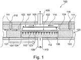
- Fig. 1 shows a furnace, in particular a continuous furnace, for controlling a temperature of at least one substrate 102.
- a housing 100 comprises an intake opening 103 and an outtake opening 104, wherein between the intake opening 103 and the outtake opening 104 a temperature-controlled section 105 is formed.
- a carrier element 120 for carrying the at least one substrate 102 is movable along a transport direction 101 through the intake opening 103 into the temperature-controlled section 105 and from the temperature-controlled section 105 through the outtake opening 104.
- a temperature controlling element 106 is arranged inside the temperature-controlled section 105 for controlling a temperature of the temperature-controlled section 105.
- the temperature-controlled section 105 comprises a gas inlet 108 through which a gas 110 is blowable for controlling a temperature of the temperature-controlled section 105.
- the temperature-controlled section 105 may be temperature controlled (e.g. heated or cooled) in order to provide a desired temperature inside the temperature-controlled section 105 for controlling a temperature of the substrate 102 with a desired temperature, respectively.
- the housing 100 forms a tunnel, through which the substrate 102 is transported during the tempering process.
- the temperature-controlled section 105 may be for example tempered between 200° to 2000° Celsius.
- the temperature controlling element 106 may be for example a plate-like element which comprises a large thermal radiation surface.
- the temperature controlling element 106 is arranged at a bottom 112 or a sidewall of the housing 100.
- the temperature controlling element 106 may be coupled to an electric power source such that the temperature controlling element 106 forms part of an electric heating.
- the temperature controlling element 106 may comprise a plurality of radiation tubes through which a heating fluid, such as heating gas or a heating liquid, may flow.
- a cooling fluid such as a cooling liquid a cooling gas, if the temperature-controlled section 105 is arranged for cooling the substrate 102.
- the temperature controlling element 106 may be arranged at the bottom 112 of the housing 100 and a below described carrier element 120 for carrying the substrate 102 may be slid or guided over the temperature controlling element 106 along the transport direction 101.
- the carrier element 120 heats up by the radiation heat from the temperature controlling element 106.
- the carrier element 120 acts itself as a temperature controlling element and heats the substrate 102 by radiation.
- the temperature controlling element 106 may act as an absorption element for absorbing thermal energy in order to cool the substrate 102.
- the gas inlet 108 is formed within the bottom 112.
- the gas 110 is for example air having a predetermined temperature from the environment.
- the gas 110 may be for example an inert gas having a predetermined temperature, such as nitrogen.
- a compressor such as an air blower may provide the gas 110 with a desired pressure such that the gas 110 is injectable through the gas inlet 108 inside the temperature-controlled section 105.
- the temperature controlling element 106 is arranged within the temperature-controlled section 105 such that the gas 110 is flowable against the temperature controlling element 106 for controlling the temperature of the temperature controlling element 106.
- the temperature controlling element 106 may comprise a plate-like shape, which may act as an air deflector. If the gas 110 is guided against the temperature controlling element 106, the temperature controlling element 106 heats up or cools down, respectively, and the temperature controlling element 106 controls the temperature of the temperature-controlled section 105 with the desired temperature.
- the gas 110 is flowable against the carrier element 120 for controlling a temperature of the carrier element 120.
- the gas 110 is flowable from the bottom 112 against the substrate 102 in such a way that the substrate 102 is liftable from the bottom 112.
- the gas inlet 108 is arranged within the housing 100, in particular the bottom 112, in such a way that the lifting force caused by the injected gas 110 acts at the substrate 102 against the gravity force of the substrate 102, such that the substrate 102 is lifted and floats.
- the substrate 102 may be free of any contact with part of the housing 100.
- mechanical defects (and e.g. non-uniform heating/cooling) of the substrate 102 caused by hits against a holding structure of the substrate 102, such as a housing 100 wall or a below described carrier element 120 may be reduced.
- the lifting force generated by the injected gas 110 may be controlled by controlling the mass flow of the gas 110.
- the mass flow of the gas 110 is controlled by a compressor and by the opening characteristics of the gas inlet 108 of the housing 100.
- the gas inlet 108 may form a nozzle or a pattern of nozzles in order to generate an adequate lifting force of the substrate 102.
- the location of the substrate 102 within the temperature-controlled section 105 may be identified by position sensors, such as cameras. Furthermore, the lifting force of the mass flow may be controlled by pressure sensors within the temperature-controlled section 105. A control unit, to which the respective sensors and the compressor are coupled, may control the lifting and floating position of the substrate 102.
- the gas 110 may be directed, e.g. by the temperature controlling element 106 acting as a deflector, along a surface of the substrate 102.
- the temperature-controlled section 105 comprises a gas outlet 109 for draining off the gas 110 from the temperature-controlled section 105.
- the intake opening 103 and the outtake opening 104 comprise a further gas inlet 111, respectively, through which a barrier gas 118 is injectable such that a gas barrier is generated for insulating the temperature-controlled section 105 from an environment of the temperature-controlled section 105.
- the barrier gas 118 may be for example air or an inert gas, such as nitrogen.
- the barrier gas 118 streams through the respective intake opening 103 or the respective outtake opening 104 such that the gas barrier is generated.
- gas 110 from the temperature-controlled section 105 is prevented from passing the gas barrier and hence may be prevented from streaming out of the temperature-controlled section 105.
- an opening i.e. an intake opening 103 and an outtake opening 104 in the housing 100, is provided, gas 110 is prevented from flowing out of the temperature-controlled section 105.
- the furnace further comprises a further temperature controlling element 107 which is arranged inside the temperature-controlled section 105 for controlling a temperature of the temperature-controlled section 105.
- the further temperature controlling element 107 is arranged with respect to the temperature controlling element 106 in such a way that the substrate 102 passes an area between the temperature controlling element 106 and the further temperature controlling element 107 when being moved along the transport direction 101 between the intake opening 103 and the outtake opening 104.
- the further temperature controlling element 107 may be formed and designed in the same manner as the above described temperature controlling element 106.
- the further temperature controlling element 107 is arranged within the temperature-controlled section 105 in such a way that the substrate 102 is arranged between both, the temperature controlling element 106 and the further temperature controlling element 107. Hence, a homogeneous tempering of the substrate 102 is provided.
- the substrate 102 is supported by the carrier element 120 for carrying the substrate 102, wherein the carrier element 120 is moveable along the transport direction 101 through the intake opening 103into the temperature-controlled section 105 and from the temperature-controlled section 105 through the outtake opening 104.
- the carrier element 120 is movable through the housing 100.
- the carrier element 120 comprises a carrier section onto which the substrate 102 is located.
- the carrier element 120 may for example comprise a rectangular, round and/or a cup-like shape.
- the carrier element 120 may be made of a high temperature resistant material, such as ceramic, CFC, graphite or metal material.
- the carrier element 120 may comprise a flat bottom 112, by which the carrier element 120 stands onto the bottom 112 of the housing 100.
- the bottom 112 comprises a low roughness for providing a low friction between the bottom 124 of the carrier element 120 and the bottom 112 of the housing 100.
- the carrier element 120 may comprise rollers onto its carrier bottom 124 in order to provide a low friction between the carrier element 120 and the bottom 112 of the housing 100.
- the carrier element 120 comprises a carrier bottom 124 onto which the substrate 102 is arrangable, wherein the carrier bottom 124 comprises a passage through which the gas 110 is flowable against the substrate 102.
- the bottom 124 of the carrier element 120 may comprise for example a passage, such as a pattern of holes or for example a mesh or a lattice, such that the gas 110 may flow through the bottom 124 of the carrier element 120 and hence heat the substrate 102 by convection. Moreover, the gas 110 flows through the bottom 124 of the carrier element 120 such that the substrate 102 may float above the carrier bottom 124.
- the carrier element 120 comprises a first edge section 121, a second edge section 122 and a recess 123 into which the substrate 102 is carriable.
- the recess 123 is formed along the transport direction 101 between the first edge section 121 and the second edge section 122, wherein the carrier element 120 is formed and arrangable within the housing 100 such that the first edge section 121 is located within the intake opening, the second edge section 122 is located within the outtake opening 104 and the recess 123 is located within the temperature-controlled section 105.
- the carrier element 120 is designed and formed in such a way, that, if a recess 123 of the carrier element 120 into which the substrate 102 is carried is located within the temperature-controlled section 105 of the furnace, a first edge section 121, e.g. an end section, is located within the intake opening 103and a second edge section 122, e.g. a further end section, is located within the outtake opening 104.
- the first edge section 121 and the second edge section 122 may comprise a larger width of the carrier element 120 than the recess 123.
- the first edge section 121 and the second edge section 122 may be protrusions of the carrier element 120 with respect to the recess 123 of the carrier element 120.
- the first edge section 121 and the second edge section 122 may comprise a similar width of the carrier element 120 with respect to the recess 123.
- the first edge section 121 and the second edge section 122 are formed at opposite ends of the carrier element 120 with respect to the transport direction 101.
- the carrier element 120 provides a proper isolation of the housing 100, in particular of the temperature-controlled section 105, because if the recess 123 of the carrier element 120 is located within the temperature-controlled section 105, the first edge section 121 and the second edge section 122 are located at the respective intake opening 103 and the respective outtake opening 104. If the first edge section 121 is located within the intake opening 103 and the second edge section 122 is located at the outtake opening 104, the size and respectively the gaps between the respective first and second edges 121, 122 and the respective intake or outtake openings 103, 104 are reduced, so that the flow volume, through which a gas 110 may flow from the temperature-controlled section 105 to the environment, is reduced.
- the carrier element 120 is moveable along the transport direction 101 through the intake opening 103 into the temperature-controlled section 105 and from the temperature-controlled section 105 through the outtake opening 104.
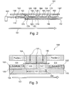
- Fig. 2 shows the housing 100 with a plurality of temperature-controlled sections 105, 114.
- Each temperature-controlled section 105, 114 may be arranged one after another along the transport direction 101, through which the substrate 102 is transportable through the housing 100.
- Each temperature-controlled section 105, 114 comprises a respective intake opening 103 and a respective outtake opening 104, 113.
- each temperature-controlled section 105, 114 may comprise a desired temperature, such that the substrate 102 or a plurality of further substrates 102 may be heated or cooled within each temperature-controlled section 105, 114 with a desired temperature.
- a first temperature-controlled section 105 may be a pre-heating zone
- a following further temperature-controlled section 114 may be a heating section, where for example the maximum temperature of the substrate 102 is reached
- a subsequent temperature-controlled section (not shown in Fig. 2 ) may be a cooling section, where the heated substrate 102 may be cooled with a desired temperature gradient (temperature per time, e.g. T/s).
- a carrier element arrangement is arranged within the tempering section 105 and a further carrier element arrangement may be arranged inside the further tempering section 114.
- the carrier element arrangement comprises at least one carrier element 120 and the further carrier element arrangement comprises at least one further carrier element 140.
- Each carrier element arrangement comprises a first end and a second end.
- the carrier element arrangement is formed and arranged within the housing 100 such that the first end is located within the intake opening 103 and the second end is located within the outtake opening 104.
- the housing 100 comprises the further outtake opening 113 and the further temperature-controlled section 114, wherein the further temperature-controlled section 114 is formed between the outtake opening 104 and the further outtake opening 113.
- the further carrier element arrangement is formed and arrangable within the housing 100 such that the further first end of the further carrier element arrangement is located within the outtake opening 104 and the further second end of the further carrier element arrangement is located within the further outtake opening 113.
- the at least one carrier element 120 of the carrier element arrangement comprises a first edge section 121, a second edge section 122 and a recess 123 within the substrate 102 is carriable, wherein the recess 123 is formed along the transport direction 101 between the first edge section 121 and the second edge section 122.
- the first edge section 121 forms the first end of the carrier element arrangement.
- the second edge section 122 of the carrier element 120 forms the second end of the carrier element arrangement.
- the carrier element arrangement may comprise a plurality of carrier elements 120 located within a common temperature controlled section 105, wherein the second edge section 122 of the carrier element 120 which is located at the downstream end of the carrier element arrangement with respect to the transport direction 101 forms the second end of the carrier element arrangement.
- the respective further carrier element 140 of the further carrier element arrangement comprises a further first edge section 121', a further second edge section 122 and a further recess 123 into which the further substrate 102 is carriable.
- the further recess 123 is formed along the transport direction 101 between the further first edge section 121' and the further second edge section 122, wherein the further carrier element 140 is formed and arrangable within the housing 100 such that the further first edge section 121' is located within the outtake opening 104, the further second edge section 122 is located within the further outtake opening 113 and the further recess 123 is located within the further temperature-controlled section 114.
- the furnace further comprises a force transmitting element 130 which is coupled to the carrier element arrangements such that the force transmitting element 130 transfers a driving force to the carrier element arrangements and the carrier elements 120, 140, respectively, for driving the carrier elements 120, 140 along the transport direction 101.
- the force transmitting element 130 is movable along the transport direction 101 the temperature-controlled section 105.
- the force transmitting element 130 may be for example a push rod or a pull rod which pulls or pushes, respectively, the carrier element arrangements along the transport direction 101.
- the force transmitting element 130 may be the further carrier element 140 of the further carrier element arrangement which is coupled by a frictional contact or by a form fit contact to the carrier element 120 of the carrier element arrangement.
- a plurality of further carrier element arrangements may be arranged along the transport direction 101 one after another in a force transmitting manner.
- the plurality of carrier elements 120, 140 of the carrier element arrangements may form a chain, for example.
- the first or the last carrier element 120, 140 of the chain may be coupled to a driving unit 150 which transfers a driving force to the other carrier elements 120, 140 of the chain.
- the plurality of carrier elements 120, 140 of the respective carrier element arrangements of the chain are coupled to each other in an exchangeable and removable manner, such that the last carrier element 120, 140 with respect to the transport direction 101 may be removed from the chain and attached to the first carrier element 120, 140 of the chain with respect to the transport direction 101.
- the force transmitting element 130 may be coupled to a driving unit 150 which is located outside of the housing 100, e.g. within the environment of the housing 100.
- the force transmitting element 130 extends from the environment, e.g. from a feeding section 115 outside of the housing 100, through the intake opening 103 of the housing 100 inside the temperature-controlled section 105.
- the force transmitting element 130 extends from the inside of the temperature-controlled section 105 through the outtake opening 104 outside of the housing 100, e.g. if the force transmitting element 130 is a pull rod.
- the driving unit 150 is for example an electrical or hydraulic motor, which generates the driving force which is transmitted by the force transmitting element 130 to the carrier elements 120, 140.
- the driving unit 150 may generate a constant driving force such that the carrier elements 120, 140 are driven through the housing 100 along the transport direction 101 continuously.
- the driving unit 150 may generate a sequential driving force, such that the carrier elements 120, 140 are moved along the transport direction 101 sequential.
- the carrier elements 120, 140 rest for a predetermined time in a desired position and are moved in a next step to another desired location was in the housing 100.
- the driving unit 150 generates a driving force with a component along a translatory direction, i.e. along the transport direction 101.
- the force transmitting element 130 may be coupled to the carrier element 120, 140 of a respective carrier element arrangement by a form fit connection, in particular a dove tail connection. Furthermore, the force transmitting element 130 comprises a contact surface and the carrier element 120 comprises a further contact surface, such that both contact surfaces may provide a frictional contact, wherein the driving force may be transferred along the direction of the respective normals of the respective contact surfaces between the force transmitting element 130 and the carrier elements 120, 140.
- the driving unit 150 is arranged outside of the housing 100.
- the force transmitting element 130 is coupled to the driving unit 150 such that the driving force is transferred from the driving unit 150 via the force transmitting element 130 to the carrier element 120.
- the housing 100 comprises a bottom 112, wherein the carrier element 120, 140 is arranged onto the bottom 112 such that the carrier element 120, 140 is slideable onto the bottom 112 along the transport direction 101.
- driven rollers or other driving means may be obsolete to be arranged inside the housing 100.
- the force transmitting element 130 is a push rod or a pull rod
- the driving force acts along a translatory direction from outside of the housing 100 to the inside of the housing 100 and pulls or pushes, respectively, the carrier elements 120, 140 along the transport direction 101.
- the bottom 112 of the housing 100 and/or the bottom 124 of the respective carrier elements 120, 140 may be formed smooth and comprise a low roughness for providing a proper slidable contact between each other.
- the housing 100 comprises a further outtake opening 113 and a further temperature-controlled section 114, wherein the further temperature-controlled section 114 is formed between the outtake opening 104 and the further outtake opening 113.
- the housing 100 may comprise a plurality of temperature-controlled sections 105, 114 which are separated by respective outtake openings 104, 113.
- Each temperature-controlled section 105, 114 may be isolated from each other by respectively arranged ends of the carrier element arrangement, i.e. the respective edges 121, 122 of carrier elements 120, 140 of the carrier element arrangements within the respective temperature-controlled sections 105, 114.
- Fig. 3 shows in more detail two carrier element arrangements, wherein one carrier element arrangement comprises the carrier element 120 and the other carrier element arrangement comprises the carrier element 140. Furthermore, an insulation section 116 (gate section 117) of the housing 100 is shown.
- the housing 100 comprises the gate section 117 between two adjacent temperature-controlled sections 105, 114.
- the housing 100 comprises the insulating section 116.
- the insulating section 116 is for example a section of the housing 100 with a protrusion for providing a small passage (intake or outtake openings 103, 104, 113) through which the respective carrier elements 120, 140 of the respective carrier element arrangements may be guided between adjacent temperature-controlled sections 105, 114.
- the insulating section 116 may be made of a thermally isolating material.
Landscapes
- Engineering & Computer Science (AREA)
- Microelectronics & Electronic Packaging (AREA)
- Power Engineering (AREA)
- Physics & Mathematics (AREA)
- Condensed Matter Physics & Semiconductors (AREA)
- General Physics & Mathematics (AREA)
- Manufacturing & Machinery (AREA)
- Computer Hardware Design (AREA)
- Mechanical Engineering (AREA)
- General Engineering & Computer Science (AREA)
- Combustion & Propulsion (AREA)
- Chemical & Material Sciences (AREA)
- Tunnel Furnaces (AREA)
- Furnace Details (AREA)
- Container, Conveyance, Adherence, Positioning, Of Wafer (AREA)
- Manufacture And Refinement Of Metals (AREA)
- Waste-Gas Treatment And Other Accessory Devices For Furnaces (AREA)
- Furnace Charging Or Discharging (AREA)
Description
- The invention relates to a furnace, in particular a continuous furnace, comprising several temperature controlling elements which are arranged inside a temperature-controlled section for controlling a temperature of the temperature-controlled section to control a temperature of a (coated) substrate. Furthermore, the present invention relates to a method for tempering a substrate by a furnace.
- In order to provide furnaces with a high capacity, tunnel furnaces or continuous furnaces are used. A continuous furnace is a continuously operating furnaces in which the material, e.g. a metal material, to be heated is fed into the furnace at an inlet, then passes through the furnace heating section and is finally removed through an outlet.
- Typically, a continuous furnace comprises several heating sections which are arranged one after another along a transportation direction of the material to be heated. For example, a continuous furnace comprises a pre-heating zone, a firing zone and a cooling zone which are arranged one after another along the transport direction of the material.
- In order to transport the material through the continuous furnace, the material is supported onto furnace rollers, or other means along which the material rolls along the transport direction. Specifically, the rollers are driven, e.g. by a driving belt, in order to transport the material along the transport direction through the furnace.
- For heating the material within a heating zone, a heating gas or process gas is injected into the respective heating zone. Due to the design of the continuous furnace, i.e. the inlet and outlet openings, it is complex to isolate the heating gas from an environment of the furnace. Hence, an accurate temperature control of a continuous furnace, as well as an energy efficient continuous furnace, is desired.
- A gas floating apparatus, gas floating-transporting apparatus, and thermal treatment apparatus is disclosed in
US 6,336,775 B1 .JP H01 167582 A FR 2 579 501 A1 - It is an object of the present invention to provide a more efficient and accurate furnace for controlling a temperature of a material.
- This object is solved by a furnace, in particular a continuous furnace, and by a method of controlling a temperature of a substrate by a furnace according to the independent claims.
- According to a first aspect of the present invention, a furnace, in particular a continuous furnace, for controlling a temperature of at least one substrate is presented. The furnace comprises a housing and a temperature controlling element. The housing comprises an intake opening and an outtake opening, wherein between the intake opening and the outtake opening a temperature-controlled section is formed. A carrier element for carrying the at least one substrate is movable along a transport direction through the intake opening into the temperature-controlled section and from the temperature-controlled section through the outtake opening. A temperature controlling element is thermally coupled to the temperature-controlled section for controlling a temperature of the temperature-controlled section, i.e. by radiation or absorption. The temperature-controlled section comprises a gas inlet through which a gas is blowable for controlling the temperature of the temperature-controlled section, i.e. by convection.
- At least one of the intake opening and the outtake opening comprised within the housing comprises a further gas inlet through which a barrier gas is injectable such that a gas barrier is generated for isolating the temperature-controlled section from a surrounding environment of the temperature-controlled section and in particular from an adjoining temperature-controlled section which is arranged upstream or downstream to the temperature controlled section.
- The barrier gas may be for example air or an inert gas, such as nitrogen. The barrier gas streams through the respective intake opening or the respective outtake opening such that the gas barrier is generated. Hence, gas from the temperature-controlled section is prevented from passing the gas barrier and hence may be prevented from streaming out of the temperature-controlled section. Hence, although an opening, i.e. an intake opening and an outtake opening in the housing, is provided, gas is prevented from flowing out of the temperature-controlled section.
- According to a further aspect of the present invention, a method for controlling a temperature of at least one substrate by a furnace is presented. According to the method, a carrier element for carrying the at least one substrate is moved along a transport direction through an intake opening into a temperature-controlled section and from the temperature-controlled section through the outtake opening. The furnace comprises a housing which comprises the intake opening and the outtake opening, wherein between the intake opening and the outtake opening the temperature-controlled section is formed. Furthermore, according to the method, the temperature of the temperature-controlled section is controlled by (radiation or absorption of thermal energy of) a temperature controlling element which is thermally coupled to the temperature-controlled section. Furthermore, a gas for (i.e. convectively) controlling a temperature of the temperature-controlled section is blown through a gas inlet into the temperature-controlled section.
- At least one of the intake opening and the outtake opening comprised within the housing of the furnace comprises a further gas inlet through which a barrier gas is injected such that a gas barrier is generated for isolating the temperature-controlled section from an outside environment of the temperature-controlled section or from an adjoining section of the temperature-controlled section.
- The furnace comprises the housing which comprises the intake opening and the outtake opening. Between the intake opening and the outtake opening, the temperature-controlled section is formed. The temperature-controlled section may be temperature controlled (heated or cooled) in order to provide a desired temperature inside the temperature-controlled section for controlling a temperature of the substrate, respectively. The housing may form a tunnel, through which the at least one substrate is transported during the heating and/or cooling process. The housing may be made of a thermal isolating material in order to isolate the volume inside the temperature-controlled section from an environment surrounding the housing.
- The housing may comprise one or a plurality of temperature-controlled sections. Each temperature-controlled section may be arranged one after another along the transport direction, with which the substrate is transported through the housing. Each temperature-controlled section may comprise a respective intake opening and a respective outtake opening. Furthermore, each temperature-controlled section may comprise a desired temperature, such that the at least one substrate may be temperature controlled (i.e. heated or cooled) within each temperature-controlled section with a desired temperature. For example, along a transport direction, a first temperature-controlled section may be a pre-heating zone, a following further temperature-controlled section may be a heating section, where for example the maximum temperature of the substrate is reached, and a subsequent temperature-controlled section may be a cooling section, where the heated substrate may be cooled with a desired temperature gradient (temperature per time, e.g. T/s).
- The substrate to be heated may be for example a ceramic element or a metal element. The metal element may be in particular a metal plate. For example, the metal plate may be pre-coated with desired alloy materials, such as Aluminium, Silicone or other desired alloy materials.
- The temperature-controlled section may be for example heated between 200° to 1000° Celsius, in particular to 2100° Celsius.
- The carrier element is movable through the housing. The carrier element comprises a carrier section onto which the substrate is located. The carrier element may for example comprise a rectangular, round and/or a cup-like shape. The carrier element may be made of a high temperature resistant material, such as ceramic material. The carrier element is made of a robust and non-flexible and non-elastic deformable material. Furthermore, the carrier element may comprise a flat bottom, by which the carrier element contacts the bottom of the housing. For example, the bottom comprises a low roughness for providing a low friction between the bottom of the carrier element and the bottom of the housing such that the carrier element slides along the bottom. In a further exemplary embodiment, the carrier element may comprise rollers onto its bottom in order to provide a low friction between the carrier element and the bottom of the housing.
- In order to achieve an accurate and efficient temperature control of the temperature-controlled section, the approach of the present invention is to provide both, a radiation heating and convection heating. The radiation heating is provided by the temperature controlling element which is thermally coupled to the temperature controlled section. A thermal coupling (i.e. a thermal interaction and a thermal energy exchange between the temperature controlling element and the inner volume of the temperature controlled section) may be achieved e.g. by arranging the temperature controlling element inside the temperature-controlled section. Furthermore, the temperature controlling element may be an integral part or a section of the housing itself, which is heated by external heating devices. For example, a section of the housing may form the temperature controlling element which is heated from an outside of the housing located heater or cooler.
- The convection heating is provided by the gas inlet, which is formed into the housing, through which the gas is flowable for controlling the temperature of the temperature-controlled section.
- In conventional approaches, continuous furnaces use convection heating, where a high mass flow of gas has to be provided inside the temperature-controlled section for adjusting accurately a temperature. Hence, the high amount of gas has to be heated, so that the efficiency is reduced.
- By the approach of the present invention, besides the convection heating, additionally a temperature controlling element provides radiation heating, so that the mass flow and hence the amount of gas may be reduced, wherein the temperature in the temperature-controlled section is still adjustable correctly.
- The temperature controlling element may be for example a plate-like element which comprises a large thermal radiation surface and/or thermal absorption surface, respectively. The material of the temperature controlling element may comprise a heat transfer coefficient of more than 50 W/(m*K), in particular more than 90 W/(m*K). The temperature controlling element may be formed for example of a metal material in order to provide proper heat transfer characteristics.
- The temperature controlling element may be for example arranged at a bottom, a top wall or a sidewall of the housing. Furthermore, the temperature controlling element may be coupled to an electric power source such that the temperature controlling element forms part of an electric heating. Alternatively or additionally, the temperature controlling element may comprise a plurality of radiation tubes through which a heating fluid, such as heating gas or a heating liquid, may flow. Alternatively, through the radiation tubes, also a cooling fluid, such as a cooling liquid or a cooling gas, if the temperature-controlled section is arranged for cooling the substrate. The temperature controlling element may also be arranged at the bottom of the housing and a below described carrier element for carrying the substrate may be slid or guided over the temperature controlling element along the transport direction. Hence, the carrier element heats up by the radiation heat from the temperature controlling element. Hence, the carrier element acts itself as a temperature controlling element and heats the substrate by radiation.
- The gas inlet may be formed within the housing, in particular within the bottom, the top or a sidewall of the housing such that the gas is injectable into the temperature-controlled section. The gas may be for example heated or cooled air from the environment or process gas. Furthermore, the gas (i.e. the process gas) may be for example an inert gas, such as nitrogen. For example, a compressor, such as an air blower, specifically a radial blower may provide the gas with a desired pressure such that the gas is injectable through the gas inlet inside the temperature-controlled section.
- According to a further exemplary embodiment, the temperature controlling element is arranged within the temperature-controlled section such that the gas is flowable against or through the temperature controlling element for controlling a temperature of the temperature controlling element. The temperature controlling element may comprise a plate-like shape, which may act as an air deflector. If the gas is guided against or through the temperature controlling element, the temperature controlling element heats up or cools down, respectively, and the temperature controlling element controls the temperature of the temperature-controlled section with the desired temperature, in particular by radiation or absorption. Hence, turbulences in the atmosphere of the temperature-controlled section may be reduced, because the temperature controlling element guides the gas along a predetermined direction.
- According to a further exemplary embodiment the gas inlet is formed in such a way that the gas is flowable against the substrate in such a way that the substrate is liftable in particular from the carrier element. Specifically, the housing comprises a bottom which comprises the gas inlet, wherein the gas is flowable from the bottom against the substrate in such a way that the substrate is liftable from the bottom.
- Specifically, the gas inlet is arranged within the housing, in particular the bottom, in such a way that the lifting force caused by the injected gas acts at the substrate against the gravity force of the substrate, such that the substrate is lifted and floats. Hence, the substrate may be free of any contact with part of the housing or carrier. Hence, mechanical defects or non-uniform heating up or cooling down due to a contact of the substrate caused by hits against a holding structure of the substrate, such as a housing wall or a below described carrier element, may be reduced.
- The lifting force generated by the injected gas may be controlled by controlling the mass flow of the gas. The mass flow of the gas is controlled by a compressor and by the opening characteristics of the gas inlet of the housing. For example, the gas inlet may form a nozzle or a pattern of nozzles in order to generate an adequate lifting force of the substrate.
- Furthermore, the location of the substrate within the temperature-controlled section may be identified by position sensors, such as cameras. Furthermore, the lifting force of the mass flow may be controlled by pressure sensors within the temperature-controlled section. A control unit, to which the respective sensors and the compressor are coupled, may control the lifting and floating position of the substrate. According to a further exemplary embodiment, the gas inlet is arranged within the temperature-controlled section in such a way, that the gas is blowable against the substrate with a streaming direction which comprises a component parallel or perpendicular with respect to the transport direction. Hence, the gas inlet maybe arranged at a sidewall of the housing and the temperature-controlled section, respectively, such that the gas inlet comprise a streaming direction which is non-parallel with respect to the direction of the force of gravity. Hence, the gas streams along a surface of the substrate. Alternatively, the gas inlet may be arranged in the bottom of the housing and the temperature controlling element deflects the gas to a desired direction of the gas flow. According to a further exemplary embodiment, the temperature-controlled section comprises a gas outlet for draining off the gas from the temperature-controlled section.
- According to a further exemplary embodiment the furnace further comprises a further temperature controlling element which is arranged inside the temperature-controlled section for controlling the temperature of the temperature-controlled section. The further temperature controlling element is arranged with respect to the temperature controlling element in such a way that the substrate passes an area between the temperature controlling element (e.g. an upper heating or cooling element) and the further temperature controlling element (e.g. a lower heating or cooling element) when being moved along the transport direction between the intake opening and the outtake opening.
- The further temperature controlling element may be formed and designed in the same manner as the above described temperature controlling element. The further temperature controlling element is arranged within the temperature-controlled section in such a way that the substrate is arranged between both, the temperature controlling element and the further temperature controlling element. Hence, a homogeneous tempering of the substrate is provided.
- According to a further exemplary embodiment, the carrier element comprises a carrier bottom onto which the substrate is arrangable, wherein the carrier bottom comprises a passage through which the gas is flowable against the substrate.
- The bottom of the carrier element may comprise for example a passage, such as a pattern of holes or for example a mesh or a lattice, such that the gas may flow through the bottom of the carrier element and hence heat the substrate by convection. Moreover, the gas flows through the bottom of the carrier element such that the substrate may float above the bottom.
- According to a further exemplary embodiment, the furnace comprises a force transmitting element which is coupled to the carrier element such that the force transmitting element transfers a driving force to the carrier element for driving the carrier element along the transport direction. The force transmitting element is movable along the transport direction.
- The force transmitting element may be for example a push rod or a pull rod which pulls or pushes, respectively, the carrier element along the transport direction. The force transmitting element may be in an exemplary embodiment a further carrier element which is coupled by a frictional contact or by a form fit contact to the carrier element. In a further exemplary embodiment, a plurality of further carrier elements maybe arranged along the transport direction one after another in a force transmitting manner. Hence, the plurality of carrier elements may form a chain, for example. The first or the last carrier element of the chain may be coupled to a driving unit which transfers a driving force to the other carrier elements of the chain. In a further exemplary embodiment, the plurality of carrier elements of the chain are coupled to each other in an exchangeable and removable manner, such that the last carrier element with respect to the transport direction may be removed from the chain and attached to the first carrier element of the chain.
- The force transmitting element may be coupled to a driving unit which is located in an exemplary embodiment outside of the housing, e.g. within the environment and hence out of the temperature-controlled section and e.g. out of the housing. The force transmitting element is coupled in particular to sections of the respective carrier element arrangements, which are located out of the respective temperature controlled sections. The force transmitting element comprises for example a pull rod or a push rod. Alternatively, the force transmitting element may extend in an exemplary embodiment from the environment through the intake opening of the housing inside the temperature-controlled section. Alternatively, the force transmitting element extends from the inside of the temperature-controlled section through the outtake opening outside of the housing, e.g. if the force transmitting element is a pull rod.
- The driving unit is for example an electrical or hydraulic motor, which generates the driving force which is transmitted by the force transmitting element to the carrier element. The driving unit may generate a constant driving force such that the carrier element is driven through the housing along the transport direction continuously. Alternatively, the driving unit may generate a sequential driving force, such that the carrier element is moved along the transport direction sequential. Hence, the carrier element rests for a predetermined time in a desired position and is moved in a next step to another desired location was in the housing. Specifically, the driving unit generates a driving force with a component along a translatory direction, i.e. along the transport direction.
- As described above, according to an exemplary embodiment, the force transmitting element is a further carrier element for carrying a further substrate.
- As described above, according to an exemplary embodiment, the force transmitting element is coupled to the carrier element such that the driving force is a (translatory) pushing force which is transferrable from the force transmitting element to the carrier element.
- As described above, according to an exemplary embodiment, the force transmitting element is coupled to the carrier element such that the driving force is a (translatory) pulling force which is transferrable from the force transmitting element to the carrier element.
- According to a further exemplary embodiment, a plurality of force transmitting elements may be applied. For example, one force transmitting element transfers a pulling force to the carrier element and another further force transmitting element transfers a pushing force to the carrier element.
- According to a further exemplary embodiment, the force transmitting element is coupled to the carrier element by a form fit connection, in particular a dove tail connection. Furthermore, the force transmitting element comprises a contact surface and the carrier element comprises a further contact surface, such that both contact surfaces may provide a frictional contact, wherein the driving force may be transferred along the direction of the respective normals of the respective contact surfaces between the force transmitting element and the carrier element.
- As described above, according to a further exemplary embodiment, a driving unit which is arranged outside of the housing is provided. The force transmitting element is coupled to the driving unit such that the driving force is transferred from the driving unit via the force transmitting element to the carrier element.
- According to a further exemplary embodiment, wherein the housing comprises a guiding system for guiding the carrier element through the housing, wherein the carrier element is coupled to the guiding system such that the carrier element is guidable along the transport direction.
- The guiding system comprises for example at least one guiding rail, wherein the respective carrier element may be coupled to the guiding rail. The carrier element may be formed for sliding along the guiding rail. Furthermore, the guiding rail or the respective carrier elements may comprise rollers, such that the carrier element may roll along the guiding rail.
- Alternatively, the guiding system may comprise a plurality of supporting sheets which are arranged along the bottom of the housing. The supporting sheets may comprise a smooth and even surface in order to provide a low friction between the carrier element and the respective supporting sheets. The carrier element may slide along the respective supporting sheets due to the low friction between the carrier element and the supporting sheets.
- Hence, the carrier element is arranged onto the bottom such that the carrier element is slideable onto the bottom along the transport direction. Hence, driven rollers or other driving means may be obsolete to be arranged inside the housing. Specifically, if the force transmitting element is a push rod or a pull rod, the driving force acts along a translatory direction from outside of the housing to the inside of the housing and pulls or pushes, respectively, the carrier element along the transport direction.
- The bottom of the housing and/or the bottom of the respective carrier elements may be formed smooth and comprise a low roughness for providing a proper slidable contact between each other. As described above, the supporting sheets may be arranged onto the bottom surface.
- According to a further exemplary embodiment, the furnace comprises a carrier element arrangement comprising at least the carrier element for carrying the substrate, wherein the carrier element arrangement comprises a first end and a second end. The carrier element arrangement is formed and arrangable within the housing such that the first end is located within the intake opening and the second end is located within the outtake opening.
- According to a further exemplary embodiment, the at least one carrier element comprises a first edge section, a second edge section and a recess within the at least one substrate is carriable. The recess is formed along the transport direction between the first edge section and the second edge section, wherein the first edge section forms the first end of the carrier element arrangement.
- According to a further exemplary embodiment, the second edge forms the second end of the carrier element arrangement. Hence, the carrier element may be formed and may be arrangable within the housing such that the first edge section is located within the intake opening, the second edge section is located within the outtake opening and the recess is located within the temperature-controlled section.
- The at least one carrier element of the carrier element arrangement is designed and formed in such a way, that, if the recess of the carrier element, into which the substrate or the plurality of substrates is carried, is located within the temperature-controlled section of the furnace, a first edge section, e.g. the first end, is located within the intake opening and a second edge section, e.g. the second end, is located within the outtake opening. The first edge and the second edge may comprise a larger width of the carrier element than the recess. In other words, the first edge and the second edge may be protrusions, i.e. thicker sections, of the carrier element with respect to the recess (thickness) of the carrier element. However, in an alternative embodiment, the first edge and the second edge may comprise a similar width of the carrier element with respect to the recess.
- According to a further exemplary embodiment, the carrier element arrangement comprises a plurality of carrier elements for carrying a plurality of substrates, wherein each of the carrier elements comprises a respective first edge section, a respective second edge section and a respective recess into which at least one substrate is carriable. The respective second edge section forms the second end of the carrier element arrangement.
- The first end and the second end are formed at opposite ends of the carrier element arrangement with respect to the transport direction. The respective first edge and the respective second edge are formed at opposite ends of a respective carrier element with respect to the transport direction.
- Hence, the carrier element arrangement provides a proper isolation of the housing, in particular of the temperature-controlled section, because if the recess of the at least one carrier element of the carrier element arrangement is located within the temperature-controlled section, the first end and the second end of the carrier element arrangement are located at the respective intake opening and the respective outtake opening. If the first end is located within the intake opening and the second end is located at the outtake opening, the size and respectively the gaps between the respective first and second ends of the carrier element arrangement and the respective intake or outtake openings are reduced, so that the flow volume, through which a gas may flow from the temperature-controlled section to the environment, is reduced.
- According to a further exemplary embodiment, the first end is dimensioned in such a way that the first end may form a loose fit connection with the intake opening of the housing, so that no or only a small gap between the first end and the intake opening exists. Accordingly, according to a further exemplary embodiment, the second end is dimensioned in such a way that the second end may form a loose fit connection with the outtake opening of the housing, so that no or only a small gap between the second end and the intake opening exists.
- According to a further exemplary embodiment, the carrier element is moveable along a transport direction through the intake opening into the temperature-controlled section and from the temperature-controlled section through the outtake opening.
- According to a further exemplary embodiment, the housing comprises a further outtake opening and a further temperature-controlled section, wherein the further temperature-controlled section is formed between the outtake opening and the further outtake opening along the transport direction. g. Hence, as described above, the housing may comprise a plurality of temperature-controlled sections which are separated by respective outtake openings. Each temperature-controlled section may be isolated from each other by respectively arranged ends of the carrier element arrangement within the respective temperature-controlled sections.
- According to a further exemplary embodiment, the furnace comprises a further carrier element arrangement comprising at least one further carrier element for carrying a further substrate, wherein the further carrier element arrangement comprises a further first end and a further second end. The further carrier element arrangement is formed and arrangable within the housing such that the further first end is located within the outtake opening and the further second end is located within the further outtake opening.
- The further carrier element arrangement may comprise one or a plurality of further carrier elements which are coupled one after another along the transport direction and which recesses are arranged within the further temperature-controlled section. The second end of the carrier element arrangement may contact or may be coupled to the further first end of the further carrier element arrangement.
- It has to be noted that embodiments of the invention have been described with reference to different subject matters. In particular, some embodiments have been described with reference to apparatus type claims whereas other embodiments have been described with reference to method type claims. However, a person skilled in the art will gather from the above and the following description that, unless other notified, in addition to any combination of features belonging to one type of subject matter also any combination between features relating to different subject matters, in particular between features of the apparatus type claims and features of the method type claims is considered as to be disclosed with this application.
- The invention will be described in more detail hereinafter with reference to examples of embodiments but to which the invention is not limited.
-
Fig. 1 shows a schematic view of a furnace comprising a temperature controlling element and a gas inlet according to an exemplary embodiment of the present invention, -
Fig. 2 shows a schematic view of a furnace comprising a carrier element and a forced transmitting element according to an exemplary embodiment of the present invention, and -
Fig. 3 shows a schematic view of a furnace comprising two carrier elements and an insulation section according to an exemplary embodiment of the present invention. - The illustrations in the drawings are schematically. In different drawings similar or identical elements are provided with the same reference signs.
-
Fig. 1 shows a furnace, in particular a continuous furnace, for controlling a temperature of at least onesubstrate 102. Ahousing 100 comprises anintake opening 103 and anouttake opening 104, wherein between theintake opening 103 and the outtake opening 104 a temperature-controlledsection 105 is formed. - A
carrier element 120 for carrying the at least onesubstrate 102 is movable along atransport direction 101 through theintake opening 103 into the temperature-controlledsection 105 and from the temperature-controlledsection 105 through theouttake opening 104. Atemperature controlling element 106 is arranged inside the temperature-controlledsection 105 for controlling a temperature of the temperature-controlledsection 105. The temperature-controlledsection 105 comprises agas inlet 108 through which agas 110 is blowable for controlling a temperature of the temperature-controlledsection 105. - The temperature-controlled
section 105 may be temperature controlled (e.g. heated or cooled) in order to provide a desired temperature inside the temperature-controlledsection 105 for controlling a temperature of thesubstrate 102 with a desired temperature, respectively. Thehousing 100 forms a tunnel, through which thesubstrate 102 is transported during the tempering process. The temperature-controlledsection 105 may be for example tempered between 200° to 2000° Celsius. - The
temperature controlling element 106 may be for example a plate-like element which comprises a large thermal radiation surface. Thetemperature controlling element 106 is arranged at a bottom 112 or a sidewall of thehousing 100. Furthermore, thetemperature controlling element 106 may be coupled to an electric power source such that thetemperature controlling element 106 forms part of an electric heating. Alternatively or additionally, thetemperature controlling element 106 may comprise a plurality of radiation tubes through which a heating fluid, such as heating gas or a heating liquid, may flow. Alternatively, through the radiation tubes, also a cooling fluid, such as a cooling liquid a cooling gas, if the temperature-controlledsection 105 is arranged for cooling thesubstrate 102. Thetemperature controlling element 106 may be arranged at the bottom 112 of thehousing 100 and a below describedcarrier element 120 for carrying thesubstrate 102 may be slid or guided over thetemperature controlling element 106 along thetransport direction 101. Hence, thecarrier element 120 heats up by the radiation heat from thetemperature controlling element 106. Hence, thecarrier element 120 acts itself as a temperature controlling element and heats thesubstrate 102 by radiation. - Furthermore, the
temperature controlling element 106 may act as an absorption element for absorbing thermal energy in order to cool thesubstrate 102. - The
gas inlet 108 is formed within thebottom 112. Thegas 110 is for example air having a predetermined temperature from the environment. Furthermore, thegas 110 may be for example an inert gas having a predetermined temperature, such as nitrogen. For example, a compressor, such as an air blower may provide thegas 110 with a desired pressure such that thegas 110 is injectable through thegas inlet 108 inside the temperature-controlledsection 105. - The
temperature controlling element 106 is arranged within the temperature-controlledsection 105 such that thegas 110 is flowable against thetemperature controlling element 106 for controlling the temperature of thetemperature controlling element 106. Thetemperature controlling element 106 may comprise a plate-like shape, which may act as an air deflector. If thegas 110 is guided against thetemperature controlling element 106, thetemperature controlling element 106 heats up or cools down, respectively, and thetemperature controlling element 106 controls the temperature of the temperature-controlledsection 105 with the desired temperature. - Furthermore, the
gas 110 is flowable against thecarrier element 120 for controlling a temperature of thecarrier element 120. - Furthermore, as shown in
Fig. 1 , thegas 110 is flowable from the bottom 112 against thesubstrate 102 in such a way that thesubstrate 102 is liftable from the bottom 112. Specifically, thegas inlet 108 is arranged within thehousing 100, in particular the bottom 112, in such a way that the lifting force caused by the injectedgas 110 acts at thesubstrate 102 against the gravity force of thesubstrate 102, such that thesubstrate 102 is lifted and floats. Hence, thesubstrate 102 may be free of any contact with part of thehousing 100. Hence, mechanical defects (and e.g. non-uniform heating/cooling) of thesubstrate 102 caused by hits against a holding structure of thesubstrate 102, such as ahousing 100 wall or a below describedcarrier element 120, may be reduced. - The lifting force generated by the injected
gas 110 may be controlled by controlling the mass flow of thegas 110. The mass flow of thegas 110 is controlled by a compressor and by the opening characteristics of thegas inlet 108 of thehousing 100. For example, thegas inlet 108 may form a nozzle or a pattern of nozzles in order to generate an adequate lifting force of thesubstrate 102. - Furthermore, the location of the
substrate 102 within the temperature-controlledsection 105 may be identified by position sensors, such as cameras. Furthermore, the lifting force of the mass flow may be controlled by pressure sensors within the temperature-controlledsection 105. A control unit, to which the respective sensors and the compressor are coupled, may control the lifting and floating position of thesubstrate 102. - Furthermore, the
gas 110 may be directed, e.g. by thetemperature controlling element 106 acting as a deflector, along a surface of thesubstrate 102. - The temperature-controlled
section 105 comprises agas outlet 109 for draining off thegas 110 from the temperature-controlledsection 105. - Furthermore, the
intake opening 103 and the outtake opening 104 comprise afurther gas inlet 111, respectively, through which abarrier gas 118 is injectable such that a gas barrier is generated for insulating the temperature-controlledsection 105 from an environment of the temperature-controlledsection 105. - The
barrier gas 118 may be for example air or an inert gas, such as nitrogen. Thebarrier gas 118 streams through therespective intake opening 103 or the respective outtake opening 104 such that the gas barrier is generated. Hence,gas 110 from the temperature-controlledsection 105 is prevented from passing the gas barrier and hence may be prevented from streaming out of the temperature-controlledsection 105. Hence, although an opening, i.e. anintake opening 103 and anouttake opening 104 in thehousing 100, is provided,gas 110 is prevented from flowing out of the temperature-controlledsection 105. - Furthermore, as shown in
Fig. 1 , the furnace further comprises a furthertemperature controlling element 107 which is arranged inside the temperature-controlledsection 105 for controlling a temperature of the temperature-controlledsection 105. The furthertemperature controlling element 107 is arranged with respect to thetemperature controlling element 106 in such a way that thesubstrate 102 passes an area between thetemperature controlling element 106 and the furthertemperature controlling element 107 when being moved along thetransport direction 101 between theintake opening 103 and theouttake opening 104. - The further
temperature controlling element 107 may be formed and designed in the same manner as the above described temperaturecontrolling element 106. The furthertemperature controlling element 107 is arranged within the temperature-controlledsection 105 in such a way that thesubstrate 102 is arranged between both, thetemperature controlling element 106 and the furthertemperature controlling element 107. Hence, a homogeneous tempering of thesubstrate 102 is provided. - As shown in
Fig. 1 , thesubstrate 102 is supported by thecarrier element 120 for carrying thesubstrate 102, wherein thecarrier element 120 is moveable along thetransport direction 101 through the intake opening 103into the temperature-controlledsection 105 and from the temperature-controlledsection 105 through theouttake opening 104. - The
carrier element 120 is movable through thehousing 100. Thecarrier element 120 comprises a carrier section onto which thesubstrate 102 is located. Thecarrier element 120 may for example comprise a rectangular, round and/or a cup-like shape. Thecarrier element 120 may be made of a high temperature resistant material, such as ceramic, CFC, graphite or metal material. Furthermore, thecarrier element 120 may comprise aflat bottom 112, by which thecarrier element 120 stands onto thebottom 112 of thehousing 100. For example, the bottom 112 comprises a low roughness for providing a low friction between the bottom 124 of thecarrier element 120 and thebottom 112 of thehousing 100. For example, thecarrier element 120 may comprise rollers onto itscarrier bottom 124 in order to provide a low friction between thecarrier element 120 and thebottom 112 of thehousing 100. - Furthermore, the
carrier element 120 comprises acarrier bottom 124 onto which thesubstrate 102 is arrangable, wherein thecarrier bottom 124 comprises a passage through which thegas 110 is flowable against thesubstrate 102. - The
bottom 124 of thecarrier element 120 may comprise for example a passage, such as a pattern of holes or for example a mesh or a lattice, such that thegas 110 may flow through thebottom 124 of thecarrier element 120 and hence heat thesubstrate 102 by convection. Moreover, thegas 110 flows through thebottom 124 of thecarrier element 120 such that thesubstrate 102 may float above thecarrier bottom 124. - The
carrier element 120 comprises afirst edge section 121, asecond edge section 122 and arecess 123 into which thesubstrate 102 is carriable. Therecess 123 is formed along thetransport direction 101 between thefirst edge section 121 and thesecond edge section 122, wherein thecarrier element 120 is formed and arrangable within thehousing 100 such that thefirst edge section 121 is located within the intake opening, thesecond edge section 122 is located within theouttake opening 104 and therecess 123 is located within the temperature-controlledsection 105. - The
carrier element 120 is designed and formed in such a way, that, if arecess 123 of thecarrier element 120 into which thesubstrate 102 is carried is located within the temperature-controlledsection 105 of the furnace, afirst edge section 121, e.g. an end section, is located within the intake opening 103and asecond edge section 122, e.g. a further end section, is located within theouttake opening 104. Thefirst edge section 121 and thesecond edge section 122 may comprise a larger width of thecarrier element 120 than therecess 123. In other words, thefirst edge section 121 and thesecond edge section 122 may be protrusions of thecarrier element 120 with respect to therecess 123 of thecarrier element 120. However, in an alternative embodiment, thefirst edge section 121 and thesecond edge section 122 may comprise a similar width of thecarrier element 120 with respect to therecess 123. - The
first edge section 121 and thesecond edge section 122 are formed at opposite ends of thecarrier element 120 with respect to thetransport direction 101. - Hence, the
carrier element 120 provides a proper isolation of thehousing 100, in particular of the temperature-controlledsection 105, because if therecess 123 of thecarrier element 120 is located within the temperature-controlledsection 105, thefirst edge section 121 and thesecond edge section 122 are located at therespective intake opening 103 and therespective outtake opening 104. If thefirst edge section 121 is located within theintake opening 103 and thesecond edge section 122 is located at the outtake opening 104, the size and respectively the gaps between the respective first andsecond edges outtake openings gas 110 may flow from the temperature-controlledsection 105 to the environment, is reduced. - The
carrier element 120 is moveable along thetransport direction 101 through theintake opening 103 into the temperature-controlledsection 105 and from the temperature-controlledsection 105 through theouttake opening 104. -
Fig. 2 shows thehousing 100 with a plurality of temperature-controlledsections section transport direction 101, through which thesubstrate 102 is transportable through thehousing 100. Each temperature-controlledsection respective intake opening 103 and a respective outtake opening 104, 113. Furthermore, each temperature-controlledsection substrate 102 or a plurality offurther substrates 102 may be heated or cooled within each temperature-controlledsection transport direction 101, a first temperature-controlledsection 105 may be a pre-heating zone, a following further temperature-controlledsection 114 may be a heating section, where for example the maximum temperature of thesubstrate 102 is reached, and a subsequent temperature-controlled section (not shown inFig. 2 ) may be a cooling section, where theheated substrate 102 may be cooled with a desired temperature gradient (temperature per time, e.g. T/s). - A carrier element arrangement is arranged within the
tempering section 105 and a further carrier element arrangement may be arranged inside thefurther tempering section 114. The carrier element arrangement comprises at least onecarrier element 120 and the further carrier element arrangement comprises at least onefurther carrier element 140. Each carrier element arrangement comprises a first end and a second end. - The carrier element arrangement is formed and arranged within the
housing 100 such that the first end is located within theintake opening 103 and the second end is located within theouttake opening 104. - The
housing 100 comprises the further outtake opening 113 and the further temperature-controlledsection 114, wherein the further temperature-controlledsection 114 is formed between theouttake opening 104 and thefurther outtake opening 113. The further carrier element arrangement is formed and arrangable within thehousing 100 such that the further first end of the further carrier element arrangement is located within theouttake opening 104 and the further second end of the further carrier element arrangement is located within thefurther outtake opening 113. - The at least one
carrier element 120 of the carrier element arrangement comprises afirst edge section 121, asecond edge section 122 and arecess 123 within thesubstrate 102 is carriable, wherein therecess 123 is formed along thetransport direction 101 between thefirst edge section 121 and thesecond edge section 122. Thefirst edge section 121 forms the first end of the carrier element arrangement. - In the exemplary embodiment shown in
Fig. 2 , thesecond edge section 122 of thecarrier element 120 forms the second end of the carrier element arrangement. Alternatively, the carrier element arrangement may comprise a plurality ofcarrier elements 120 located within a common temperature controlledsection 105, wherein thesecond edge section 122 of thecarrier element 120 which is located at the downstream end of the carrier element arrangement with respect to thetransport direction 101 forms the second end of the carrier element arrangement. - The respective
further carrier element 140 of the further carrier element arrangement comprises a further first edge section 121', a furthersecond edge section 122 and afurther recess 123 into which thefurther substrate 102 is carriable. Thefurther recess 123 is formed along thetransport direction 101 between the further first edge section 121' and the furthersecond edge section 122, wherein thefurther carrier element 140 is formed and arrangable within thehousing 100 such that the further first edge section 121' is located within the outtake opening 104, the furthersecond edge section 122 is located within the further outtake opening 113 and thefurther recess 123 is located within the further temperature-controlledsection 114. - The furnace further comprises a
force transmitting element 130 which is coupled to the carrier element arrangements such that theforce transmitting element 130 transfers a driving force to the carrier element arrangements and thecarrier elements carrier elements transport direction 101. Theforce transmitting element 130 is movable along thetransport direction 101 the temperature-controlledsection 105. - The
force transmitting element 130 may be for example a push rod or a pull rod which pulls or pushes, respectively, the carrier element arrangements along thetransport direction 101. Theforce transmitting element 130 may be thefurther carrier element 140 of the further carrier element arrangement which is coupled by a frictional contact or by a form fit contact to thecarrier element 120 of the carrier element arrangement. A plurality of further carrier element arrangements may be arranged along thetransport direction 101 one after another in a force transmitting manner. Hence, the plurality ofcarrier elements last carrier element driving unit 150 which transfers a driving force to theother carrier elements carrier elements last carrier element transport direction 101 may be removed from the chain and attached to thefirst carrier element transport direction 101. - The
force transmitting element 130 may be coupled to adriving unit 150 which is located outside of thehousing 100, e.g. within the environment of thehousing 100. Hence, theforce transmitting element 130 extends from the environment, e.g. from afeeding section 115 outside of thehousing 100, through theintake opening 103 of thehousing 100 inside the temperature-controlledsection 105. Alternatively, theforce transmitting element 130 extends from the inside of the temperature-controlledsection 105 through the outtake opening 104 outside of thehousing 100, e.g. if theforce transmitting element 130 is a pull rod. - The driving
unit 150 is for example an electrical or hydraulic motor, which generates the driving force which is transmitted by theforce transmitting element 130 to thecarrier elements unit 150 may generate a constant driving force such that thecarrier elements housing 100 along thetransport direction 101 continuously. Alternatively, the drivingunit 150 may generate a sequential driving force, such that thecarrier elements transport direction 101 sequential. Hence, thecarrier elements housing 100. Specifically, the drivingunit 150 generates a driving force with a component along a translatory direction, i.e. along thetransport direction 101. - The
force transmitting element 130 may be coupled to thecarrier element force transmitting element 130 comprises a contact surface and thecarrier element 120 comprises a further contact surface, such that both contact surfaces may provide a frictional contact, wherein the driving force may be transferred along the direction of the respective normals of the respective contact surfaces between theforce transmitting element 130 and thecarrier elements - The driving
unit 150 is arranged outside of thehousing 100. Theforce transmitting element 130 is coupled to thedriving unit 150 such that the driving force is transferred from the drivingunit 150 via theforce transmitting element 130 to thecarrier element 120. - The
housing 100 comprises a bottom 112, wherein thecarrier element carrier element transport direction 101. Hence, driven rollers or other driving means may be obsolete to be arranged inside thehousing 100. Specifically, if theforce transmitting element 130 is a push rod or a pull rod, the driving force acts along a translatory direction from outside of thehousing 100 to the inside of thehousing 100 and pulls or pushes, respectively, thecarrier elements transport direction 101. - The
bottom 112 of thehousing 100 and/or thebottom 124 of therespective carrier elements - Furthermore, the
housing 100 comprises a further outtake opening 113 and a further temperature-controlledsection 114, wherein the further temperature-controlledsection 114 is formed between theouttake opening 104 and thefurther outtake opening 113. Hence, as described above, thehousing 100 may comprise a plurality of temperature-controlledsections respective outtake openings section respective edges carrier elements sections -
Fig. 3 shows in more detail two carrier element arrangements, wherein one carrier element arrangement comprises thecarrier element 120 and the other carrier element arrangement comprises thecarrier element 140. Furthermore, an insulation section 116 (gate section 117) of thehousing 100 is shown. - The
housing 100 comprises thegate section 117 between two adjacent temperature-controlledsections gate section 117, thehousing 100 comprises the insulatingsection 116. The insulatingsection 116 is for example a section of thehousing 100 with a protrusion for providing a small passage (intake orouttake openings respective carrier elements sections section 116 may be made of a thermally isolating material. - It should be noted that the term "comprising" does not exclude other elements or steps and "a" or "an" does not exclude a plurality. Also elements described in association with different embodiments may be combined. It should also be noted that reference signs in the claims should not be construed as limiting the scope of the claims.
-
- 100
- housing
- 101
- transport direction
- 102
- substrate
- 103
- intake opening
- 104
- outtake opening
- 105
- temperature-controlled section
- 106
- temperature controlling element
- 107
- further temperature controlling element
- 108
- gas inlet
- 109
- gas outlet
- 110
- gas
- 111
- further gas inlet
- 112
- bottom
- 113
- further outtake opening
- 114
- further temperature-controlled section
- 115
- feeding section
- 116
- insulation section
- 117
- gate section
- 118
- barrier gas
- 120
- carrier element
- 121
- first edge section
- 122
- second edge section
- 123
- recess
- 124
- carrier bottom
- 130
- force transmitting element
- 140
- further carrier element
- 150
- driving unit
Claims (21)
- Furnace, in particular a continuous furnace, for controlling a temperature of at least one substrate (102), the furnace comprising
a housing (100) which comprises an intake opening (103) and an outtake opening (104),
wherein between the intake opening (103) and the outtake opening (104) a temperature-controlled section (105) is formed,
a carrier element (120) for carrying the at least one substrate (102),
wherein the carrier element (120) is movable along a transport direction (101) through the intake opening (103) into the temperature-controlled section (105) and from the temperature-controlled section (105) through the outtake opening (104),
wherein a temperature controlling element (106) is thermally coupled to the temperature-controlled section (105) for controlling the temperature of the temperature-controlled section (105),
wherein the temperature-controlled section (105) comprises a gas inlet (108) through which a gas (110) is blowable for controlling the temperature of the temperature-controlled section (105),
characterized in that,
at least one of the intake opening (103) and the outtake opening (104) comprised within the housing (100) comprises a further gas inlet (111) through which a barrier gas (118) is injectable such that a gas barrier is generated for isolating the temperature-controlled section (105) from an outside environment of the temperature-controlled section (105) or from an adjoining section of the temperature-controlled section (105). - Furnace according to claim 1,
wherein the temperature controlling element (106) is arranged inside the temperature-controlled section (105) such that the gas (110) is flowable against or through the temperature controlling element (106) for controlling the temperature of the temperature controlling element (106) to carry heat convectively to or away from the substrate (102). - Furnace according to claim 1 or 2,
wherein the gas inlet (108) is formed in such a way that the gas (110) is flowable against the substrate (102) in such a way that the substrate (102) is liftable. - Furnace according to one of the claims 1 to 3,
wherein the gas inlet (108) is arranged in the temperature-controlled section (105) in such a way, that the gas (110) is blowable against the substrate (102) with a streaming direction which comprises a component parallel or perpendicular with respect to the transport direction (101). - Furnace according to one of the claims 1 to 4,
wherein the temperature-controlled section (105) comprises a gas outlet (109) for draining off the gas (110) from the temperature-controlled section (105). - Furnace according to one of the claims 1 to 5, further comprising
a further temperature controlling element (107) which is arranged inside the temperature-controlled section (105) for controlling the temperature of the temperature-controlled section (105),
wherein the further temperature controlling element (107) is arranged with respect to the temperature controlling element (106) in such a way that the substrate (102) passes an area between the temperature controlling element (106) and the further temperature controlling element (107) when being moved along the transport direction (101) between the intake opening (103) and the outtake opening (104). - Furnace according to one of the claims 1 to 6,
wherein the carrier element (120) comprises a carrier bottom (124) onto which the substrate (102) is arrangable,
wherein the carrier bottom (124) comprises a passage through which the gas (110) is flowable against the substrate (102). - Furnace according to one of the claims 1 to 7, further comprising
a force transmitting element (130) which is coupled to the carrier element (120) such that the force transmitting element (130) transfers a driving force to the carrier element (120) for driving the carrier element (120) along the transport direction (101),
wherein the force transmitting element (130) is movable along the transport direction (101). - Furnace according to claim 8,
wherein the force transmitting element (130) is a further carrier element (140) for carrying a further substrate (102). - Furnace according to claims 8 or 9,
wherein the force transmitting element (130) is coupled to the carrier element (120) such that the driving force is a pushing force which is transferrable from the force transmitting element (130) to the carrier element (120). - Furnace according to one of the claims 8 to 10,
wherein the force transmitting element (130) is coupled to the carrier element (120) such that the driving force is a pulling force which is transferrable from the force transmitting element (130) to the carrier element (120). - Furnace according to one of the claims 8 to 11,
wherein the force transmitting element (130) is coupled to the carrier element (120) by a form fit connection, in particular a dove tail connection. - Furnace according to one of the claims 8 to 12, further comprising
a driving unit (150) which is arranged outside of the housing (100),
wherein the force transmitting element (130) is coupled to the driving unit (150) such that the driving force is transferred from the driving unit (150) via the force transmitting element (130) to the carrier element (120). - Furnace according to one of the claims 1 to 13,
wherein the housing (100) comprises a guiding system for guiding the carrier element (120) through the housing,
wherein the carrier element (120) is coupled to the guiding system such that the carrier element (120) is guidable along the transport direction (101). - Furnace according to one of the claims 1 to 14, further comprising
a carrier element arrangement comprising at least the carrier element (120) for carrying the substrate (102),
wherein the carrier element arrangement comprises a first end and a second end,
wherein the carrier element arrangement is formed and arrangable within the housing (100) such that the first end is located within the intake opening (103) and the second end is located within the outtake opening (104). - Furnace according to claim 15,
wherein the at least one carrier element (120) comprises a first edge section (121), a second edge section (122) and a recess (123) within the substrate (102) is carriable,
wherein the recess (123) is formed along the transport direction (101) between the first edge section (121) and the second edge section (122), wherein the first edge section forms the first end of the carrier element arrangement. - Furnace according to claim 16,
wherein the second edge section (122) forms the second end of the carrier element arrangement. - Furnace according to claim 16,
wherein the carrier element arrangement comprises a further carrier element (140) for carrying a further substrate (102),
wherein the further carrier element (140) comprises a further first edge section, a further second edge section and a further recess into which the further substrate (102) is carriable,
wherein the further second edge section forms the second end of the carrier element arrangement. - Furnace according to one of the claims 1 to 18,
wherein the housing (100) comprises a further outtake opening (113) and a further temperature-controlled section (114),
wherein the further temperature-controlled section (114) is formed between the outtake opening (104) and the further outtake opening (113). - Furnace according to claim 19, further comprising
a further carrier element arrangement comprising at least one further carrier element (140) for carrying a further substrate (102),
wherein the further carrier element arrangement comprises a further first end and a further second end,
wherein the further carrier element arrangement is formed and arrangable within the housing (100) such that the further first end is located within the outtake opening (104) and the further second end is located within the further outtake opening (113). - Method for controlling a temperature of at least one substrate (102) by a furnace, the method comprising
moving a carrier element (120) for carrying the at least one substrate (102) along a transport direction (101) through an intake opening (103) into a temperature-controlled section (105) and from the temperature-controlled section (105) through the outtake opening (104),
wherein the furnace comprises a housing (100) which comprises the intake opening (103) and the outtake opening (104),
wherein between the intake opening (103) and the outtake opening (104) the temperature-controlled section (105) is formed,
controlling the temperature of the temperature-controlled section (105) by a temperature controlling element (106) which is thermally coupled to the temperature-controlled section (105), and
blowing a gas (110) for controlling the temperature of the temperature-controlled section (105) through a gas inlet (108) into the temperature-controlled section (105),
characterized in that,
at least one of the intake opening (103) and the outtake opening (104) comprised within the housing of the furnace comprises a further gas inlet (111) through which a barrier gas (118) is injected such that a gas barrier is generated for isolating the temperature-controlled section (105) from an outside environment of the temperature-controlled section (105) or from an adjoining section of the temperature-controlled section (105).
Applications Claiming Priority (2)
| Application Number | Priority Date | Filing Date | Title |
|---|---|---|---|
| GBGB1317170.7A GB201317170D0 (en) | 2013-09-27 | 2013-09-27 | Furnace with a convection and radiation heating |
| PCT/EP2014/070580 WO2015044320A1 (en) | 2013-09-27 | 2014-09-25 | Furnace with a convection and radiation heating |
Publications (2)
| Publication Number | Publication Date |
|---|---|
| EP3049744A1 EP3049744A1 (en) | 2016-08-03 |
| EP3049744B1 true EP3049744B1 (en) | 2018-10-24 |
Family
ID=49553514
Family Applications (1)
| Application Number | Title | Priority Date | Filing Date |
|---|---|---|---|
| EP14783783.5A Not-in-force EP3049744B1 (en) | 2013-09-27 | 2014-09-25 | Furnace with a convection and radiation heating |
Country Status (7)
| Country | Link |
|---|---|
| US (1) | US9970709B2 (en) |
| EP (1) | EP3049744B1 (en) |
| JP (1) | JP6491216B2 (en) |
| KR (1) | KR20160068820A (en) |
| CN (1) | CN107110602B (en) |
| GB (1) | GB201317170D0 (en) |
| WO (1) | WO2015044320A1 (en) |
Families Citing this family (2)
| Publication number | Priority date | Publication date | Assignee | Title |
|---|---|---|---|---|
| GB201317194D0 (en) * | 2013-09-27 | 2013-11-13 | Ebner Ind Ofenbau | |
| JP7477754B2 (en) * | 2020-03-30 | 2024-05-02 | 日本製鉄株式会社 | Heating furnace and heating method |
Citations (1)
| Publication number | Priority date | Publication date | Assignee | Title |
|---|---|---|---|---|
| FR2579501A1 (en) * | 1985-03-30 | 1986-10-03 | Neitz Heinrich Verwaltung | METHOD AND DEVICE FOR BRAZING ALUMINUM PARTS |
Family Cites Families (20)
| Publication number | Priority date | Publication date | Assignee | Title |
|---|---|---|---|---|
| JPS61149781A (en) * | 1984-12-24 | 1986-07-08 | 日立金属株式会社 | Continuous furnace for sintering atmosphere |
| US4767324A (en) * | 1987-05-26 | 1988-08-30 | General Electric Company | Transition section for muffle furnace |
| JPH01167582A (en) * | 1987-12-23 | 1989-07-03 | Shinagawa Refract Co Ltd | Levitating and transporting burning furnace for substance to be heated and burning method therefor |
| JP2910061B2 (en) * | 1989-06-30 | 1999-06-23 | 松下電器産業株式会社 | Firing furnace |
| JP4090585B2 (en) * | 1997-08-04 | 2008-05-28 | 松下電器産業株式会社 | Heat treatment method for target object and apparatus therefor |
| MY117325A (en) * | 1997-08-04 | 2004-06-30 | Matsushita Electric Ind Co Ltd | Method of heat treating object and apparatus for the same. |
| JPH11281259A (en) * | 1998-03-27 | 1999-10-15 | Tokai Konetsu Kogyo Co Ltd | Continuous atmospheric furnace |
| US5915958A (en) * | 1998-06-18 | 1999-06-29 | Ross Air Systems, Inc. | Convertible apparatus for heat treating materials |
| JP2000128346A (en) * | 1998-08-20 | 2000-05-09 | Matsushita Electric Ind Co Ltd | Floating device, floating carrier and heat treatment device |
| US6336775B1 (en) * | 1998-08-20 | 2002-01-08 | Matsushita Electric Industrial Co., Ltd. | Gas floating apparatus, gas floating-transporting apparatus, and thermal treatment apparatus |
| JP2001066751A (en) * | 1999-02-16 | 2001-03-16 | Fuji Photo Film Co Ltd | Image-forming apparatus |
| JP3547724B2 (en) * | 2001-09-25 | 2004-07-28 | 沖電気工業株式会社 | Resist pattern baking apparatus and resist pattern forming method |
| JP2003329372A (en) * | 2002-05-14 | 2003-11-19 | Nittetsu Elex Co Ltd | Continuous treatment equipment |
| JP4741307B2 (en) * | 2005-05-20 | 2011-08-03 | 富士フイルム株式会社 | Heating apparatus and heating method |
| JP2008020112A (en) * | 2006-07-12 | 2008-01-31 | Fujitsu Hitachi Plasma Display Ltd | Heating treatment method and device |
| CN101257060B (en) * | 2008-03-05 | 2012-05-23 | 常州亿晶光电科技有限公司 | Solar cell sintered furnace temperature zone partition apparatus |
| US20100127418A1 (en) * | 2008-11-25 | 2010-05-27 | Ronald Alan Davidson | Methods For Continuous Firing Of Shaped Bodies And Roller Hearth Furnaces Therefor |
| CN201331256Y (en) * | 2008-12-15 | 2009-10-21 | 合肥恒力电子技术开发公司 | Air blocking device for high temperature furnace tube |
| DE102009037299A1 (en) * | 2009-08-14 | 2011-08-04 | Leybold Optics GmbH, 63755 | Device and treatment chamber for the thermal treatment of substrates |
| US9163877B2 (en) * | 2011-06-07 | 2015-10-20 | Berndorf Band Gmbh | Conveyor oven |
-
2013
- 2013-09-27 GB GBGB1317170.7A patent/GB201317170D0/en not_active Ceased
-
2014
- 2014-09-25 WO PCT/EP2014/070580 patent/WO2015044320A1/en active Application Filing
- 2014-09-25 KR KR1020167011235A patent/KR20160068820A/en not_active Application Discontinuation
- 2014-09-25 EP EP14783783.5A patent/EP3049744B1/en not_active Not-in-force
- 2014-09-25 JP JP2016544761A patent/JP6491216B2/en not_active Expired - Fee Related
- 2014-09-25 CN CN201480065142.4A patent/CN107110602B/en not_active Expired - Fee Related
-
2016
- 2016-03-17 US US15/072,821 patent/US9970709B2/en not_active Expired - Fee Related
Patent Citations (1)
| Publication number | Priority date | Publication date | Assignee | Title |
|---|---|---|---|---|
| FR2579501A1 (en) * | 1985-03-30 | 1986-10-03 | Neitz Heinrich Verwaltung | METHOD AND DEVICE FOR BRAZING ALUMINUM PARTS |
Also Published As
| Publication number | Publication date |
|---|---|
| WO2015044320A1 (en) | 2015-04-02 |
| US9970709B2 (en) | 2018-05-15 |
| JP6491216B2 (en) | 2019-03-27 |
| EP3049744A1 (en) | 2016-08-03 |
| US20160290719A1 (en) | 2016-10-06 |
| CN107110602A (en) | 2017-08-29 |
| GB201317170D0 (en) | 2013-11-06 |
| KR20160068820A (en) | 2016-06-15 |
| JP2016536557A (en) | 2016-11-24 |
| CN107110602B (en) | 2019-11-15 |
Similar Documents
| Publication | Publication Date | Title |
|---|---|---|
| CN103100776B (en) | Reflow soldering system | |
| KR100619463B1 (en) | Continuous sintering furnace and use thereof | |
| FI86055C (en) | Device for thermosetting of glass sheets | |
| CN108695194B (en) | Substrate heating apparatus, substrate processing system, and substrate heating method | |
| US9970709B2 (en) | Furnace with a convection and radiation heating | |
| JP2006245110A5 (en) | ||
| US8865058B2 (en) | Heat treatment furnace | |
| JP5335724B2 (en) | Drying processing equipment | |
| US20030118966A1 (en) | Thermal treatment apparatus | |
| US8692161B2 (en) | Furnace system with case integrated cooling system | |
| KR101358285B1 (en) | Continuous firing furnace | |
| JP2009014227A (en) | Heat treatment furnace | |
| TW469338B (en) | Substrate heating method and the continuous heat treatment furnace thereof | |
| EP3049743B1 (en) | Furnace comprising a sealed temperature-controlled section | |
| JP4661766B2 (en) | Method and apparatus for firing honeycomb structure | |
| JP5446653B2 (en) | Heat treatment equipment | |
| KR100776370B1 (en) | Burning apparatus | |
| US20240213396A1 (en) | Thermal decomposition apparatus and thermal decomposition method applying the same | |
| CN107256841B (en) | Quick thermal annealing machine | |
| JP2023080567A (en) | heat treatment furnace | |
| CN116278066A (en) | Full-automatic multi-temperature-zone continuous annealing furnace | |
| BE1020589A5 (en) | CONTROLLED COOLING OF A FLAT GLASS PRODUCT. | |
| JP2022117896A (en) | Vertical heating furnace | |
| JP2007017028A (en) | Heat treatment furnace, and method for manufacturing flat display panel | |
| JP2008180433A (en) | Heat-treating furnace for tabular member |
Legal Events
| Date | Code | Title | Description |
|---|---|---|---|
| PUAI | Public reference made under article 153(3) epc to a published international application that has entered the european phase |
Free format text: ORIGINAL CODE: 0009012 |
|
| 17P | Request for examination filed |
Effective date: 20160324 |
|
| AK | Designated contracting states |
Kind code of ref document: A1 Designated state(s): AL AT BE BG CH CY CZ DE DK EE ES FI FR GB GR HR HU IE IS IT LI LT LU LV MC MK MT NL NO PL PT RO RS SE SI SK SM TR |
|
| AX | Request for extension of the european patent |
Extension state: BA ME |
|
| DAX | Request for extension of the european patent (deleted) | ||
| STAA | Information on the status of an ep patent application or granted ep patent |
Free format text: STATUS: EXAMINATION IS IN PROGRESS |
|
| 17Q | First examination report despatched |
Effective date: 20170411 |
|
| REG | Reference to a national code |
Ref country code: DE Ref legal event code: R079 Ref document number: 602014034732 Country of ref document: DE Free format text: PREVIOUS MAIN CLASS: F27B0009100000 Ipc: F27B0009200000 |
|
| GRAP | Despatch of communication of intention to grant a patent |
Free format text: ORIGINAL CODE: EPIDOSNIGR1 |
|
| STAA | Information on the status of an ep patent application or granted ep patent |
Free format text: STATUS: GRANT OF PATENT IS INTENDED |
|
| RIC1 | Information provided on ipc code assigned before grant |
Ipc: H01L 21/677 20060101ALI20180508BHEP Ipc: F27B 9/28 20060101ALI20180508BHEP Ipc: F27B 9/24 20060101ALI20180508BHEP Ipc: F27B 9/06 20060101ALI20180508BHEP Ipc: F27D 19/00 20060101ALI20180508BHEP Ipc: F27B 9/20 20060101AFI20180508BHEP Ipc: H01L 21/67 20060101ALI20180508BHEP Ipc: F27B 17/00 20060101ALI20180508BHEP |
|
| INTG | Intention to grant announced |
Effective date: 20180606 |
|
| GRAS | Grant fee paid |
Free format text: ORIGINAL CODE: EPIDOSNIGR3 |
|
| GRAA | (expected) grant |
Free format text: ORIGINAL CODE: 0009210 |
|
| STAA | Information on the status of an ep patent application or granted ep patent |
Free format text: STATUS: THE PATENT HAS BEEN GRANTED |
|
| AK | Designated contracting states |
Kind code of ref document: B1 Designated state(s): AL AT BE BG CH CY CZ DE DK EE ES FI FR GB GR HR HU IE IS IT LI LT LU LV MC MK MT NL NO PL PT RO RS SE SI SK SM TR |
|
| REG | Reference to a national code |
Ref country code: CH Ref legal event code: EP |
|
| REG | Reference to a national code |
Ref country code: IE Ref legal event code: FG4D |
|
| REG | Reference to a national code |
Ref country code: AT Ref legal event code: REF Ref document number: 1057188 Country of ref document: AT Kind code of ref document: T Effective date: 20181115 |
|
| REG | Reference to a national code |
Ref country code: DE Ref legal event code: R096 Ref document number: 602014034732 Country of ref document: DE |
|
| REG | Reference to a national code |
Ref country code: NL Ref legal event code: FP |
|
| REG | Reference to a national code |
Ref country code: CH Ref legal event code: NV Representative=s name: KELLER AND PARTNER PATENTANWAELTE AG, CH |
|
| REG | Reference to a national code |
Ref country code: SE Ref legal event code: TRGR |
|
| REG | Reference to a national code |
Ref country code: LT Ref legal event code: MG4D |
|
| PG25 | Lapsed in a contracting state [announced via postgrant information from national office to epo] |
Ref country code: HR Free format text: LAPSE BECAUSE OF FAILURE TO SUBMIT A TRANSLATION OF THE DESCRIPTION OR TO PAY THE FEE WITHIN THE PRESCRIBED TIME-LIMIT Effective date: 20181024 Ref country code: LT Free format text: LAPSE BECAUSE OF FAILURE TO SUBMIT A TRANSLATION OF THE DESCRIPTION OR TO PAY THE FEE WITHIN THE PRESCRIBED TIME-LIMIT Effective date: 20181024 Ref country code: NO Free format text: LAPSE BECAUSE OF FAILURE TO SUBMIT A TRANSLATION OF THE DESCRIPTION OR TO PAY THE FEE WITHIN THE PRESCRIBED TIME-LIMIT Effective date: 20190124 Ref country code: BG Free format text: LAPSE BECAUSE OF FAILURE TO SUBMIT A TRANSLATION OF THE DESCRIPTION OR TO PAY THE FEE WITHIN THE PRESCRIBED TIME-LIMIT Effective date: 20190124 Ref country code: PL Free format text: LAPSE BECAUSE OF FAILURE TO SUBMIT A TRANSLATION OF THE DESCRIPTION OR TO PAY THE FEE WITHIN THE PRESCRIBED TIME-LIMIT Effective date: 20181024 Ref country code: FI Free format text: LAPSE BECAUSE OF FAILURE TO SUBMIT A TRANSLATION OF THE DESCRIPTION OR TO PAY THE FEE WITHIN THE PRESCRIBED TIME-LIMIT Effective date: 20181024 Ref country code: LV Free format text: LAPSE BECAUSE OF FAILURE TO SUBMIT A TRANSLATION OF THE DESCRIPTION OR TO PAY THE FEE WITHIN THE PRESCRIBED TIME-LIMIT Effective date: 20181024 Ref country code: ES Free format text: LAPSE BECAUSE OF FAILURE TO SUBMIT A TRANSLATION OF THE DESCRIPTION OR TO PAY THE FEE WITHIN THE PRESCRIBED TIME-LIMIT Effective date: 20181024 Ref country code: IS Free format text: LAPSE BECAUSE OF FAILURE TO SUBMIT A TRANSLATION OF THE DESCRIPTION OR TO PAY THE FEE WITHIN THE PRESCRIBED TIME-LIMIT Effective date: 20190224 |
|
| PG25 | Lapsed in a contracting state [announced via postgrant information from national office to epo] |
Ref country code: GR Free format text: LAPSE BECAUSE OF FAILURE TO SUBMIT A TRANSLATION OF THE DESCRIPTION OR TO PAY THE FEE WITHIN THE PRESCRIBED TIME-LIMIT Effective date: 20190125 Ref country code: PT Free format text: LAPSE BECAUSE OF FAILURE TO SUBMIT A TRANSLATION OF THE DESCRIPTION OR TO PAY THE FEE WITHIN THE PRESCRIBED TIME-LIMIT Effective date: 20190224 Ref country code: RS Free format text: LAPSE BECAUSE OF FAILURE TO SUBMIT A TRANSLATION OF THE DESCRIPTION OR TO PAY THE FEE WITHIN THE PRESCRIBED TIME-LIMIT Effective date: 20181024 Ref country code: AL Free format text: LAPSE BECAUSE OF FAILURE TO SUBMIT A TRANSLATION OF THE DESCRIPTION OR TO PAY THE FEE WITHIN THE PRESCRIBED TIME-LIMIT Effective date: 20181024 |
|
| REG | Reference to a national code |
Ref country code: DE Ref legal event code: R097 Ref document number: 602014034732 Country of ref document: DE |
|
| PG25 | Lapsed in a contracting state [announced via postgrant information from national office to epo] |
Ref country code: DK Free format text: LAPSE BECAUSE OF FAILURE TO SUBMIT A TRANSLATION OF THE DESCRIPTION OR TO PAY THE FEE WITHIN THE PRESCRIBED TIME-LIMIT Effective date: 20181024 Ref country code: CZ Free format text: LAPSE BECAUSE OF FAILURE TO SUBMIT A TRANSLATION OF THE DESCRIPTION OR TO PAY THE FEE WITHIN THE PRESCRIBED TIME-LIMIT Effective date: 20181024 |
|
| PG25 | Lapsed in a contracting state [announced via postgrant information from national office to epo] |
Ref country code: SK Free format text: LAPSE BECAUSE OF FAILURE TO SUBMIT A TRANSLATION OF THE DESCRIPTION OR TO PAY THE FEE WITHIN THE PRESCRIBED TIME-LIMIT Effective date: 20181024 Ref country code: SM Free format text: LAPSE BECAUSE OF FAILURE TO SUBMIT A TRANSLATION OF THE DESCRIPTION OR TO PAY THE FEE WITHIN THE PRESCRIBED TIME-LIMIT Effective date: 20181024 Ref country code: EE Free format text: LAPSE BECAUSE OF FAILURE TO SUBMIT A TRANSLATION OF THE DESCRIPTION OR TO PAY THE FEE WITHIN THE PRESCRIBED TIME-LIMIT Effective date: 20181024 Ref country code: RO Free format text: LAPSE BECAUSE OF FAILURE TO SUBMIT A TRANSLATION OF THE DESCRIPTION OR TO PAY THE FEE WITHIN THE PRESCRIBED TIME-LIMIT Effective date: 20181024 |
|
| PLBE | No opposition filed within time limit |
Free format text: ORIGINAL CODE: 0009261 |
|
| STAA | Information on the status of an ep patent application or granted ep patent |
Free format text: STATUS: NO OPPOSITION FILED WITHIN TIME LIMIT |
|
| 26N | No opposition filed |
Effective date: 20190725 |
|
| PG25 | Lapsed in a contracting state [announced via postgrant information from national office to epo] |
Ref country code: SI Free format text: LAPSE BECAUSE OF FAILURE TO SUBMIT A TRANSLATION OF THE DESCRIPTION OR TO PAY THE FEE WITHIN THE PRESCRIBED TIME-LIMIT Effective date: 20181024 |
|
| PGFP | Annual fee paid to national office [announced via postgrant information from national office to epo] |
Ref country code: SE Payment date: 20190918 Year of fee payment: 6 Ref country code: FR Payment date: 20190927 Year of fee payment: 6 Ref country code: IT Payment date: 20190925 Year of fee payment: 6 Ref country code: NL Payment date: 20190918 Year of fee payment: 6 |
|
| PGFP | Annual fee paid to national office [announced via postgrant information from national office to epo] |
Ref country code: AT Payment date: 20190916 Year of fee payment: 6 Ref country code: GB Payment date: 20190920 Year of fee payment: 6 |
|
| PGFP | Annual fee paid to national office [announced via postgrant information from national office to epo] |
Ref country code: DE Payment date: 20191023 Year of fee payment: 6 Ref country code: CH Payment date: 20190919 Year of fee payment: 6 |
|
| PG25 | Lapsed in a contracting state [announced via postgrant information from national office to epo] |
Ref country code: TR Free format text: LAPSE BECAUSE OF FAILURE TO SUBMIT A TRANSLATION OF THE DESCRIPTION OR TO PAY THE FEE WITHIN THE PRESCRIBED TIME-LIMIT Effective date: 20181024 |
|
| PG25 | Lapsed in a contracting state [announced via postgrant information from national office to epo] |
Ref country code: MC Free format text: LAPSE BECAUSE OF FAILURE TO SUBMIT A TRANSLATION OF THE DESCRIPTION OR TO PAY THE FEE WITHIN THE PRESCRIBED TIME-LIMIT Effective date: 20181024 |
|
| PG25 | Lapsed in a contracting state [announced via postgrant information from national office to epo] |
Ref country code: LU Free format text: LAPSE BECAUSE OF NON-PAYMENT OF DUE FEES Effective date: 20190925 Ref country code: IE Free format text: LAPSE BECAUSE OF NON-PAYMENT OF DUE FEES Effective date: 20190925 |
|
| REG | Reference to a national code |
Ref country code: BE Ref legal event code: MM Effective date: 20190930 |
|
| PG25 | Lapsed in a contracting state [announced via postgrant information from national office to epo] |
Ref country code: BE Free format text: LAPSE BECAUSE OF NON-PAYMENT OF DUE FEES Effective date: 20190930 |
|
| REG | Reference to a national code |
Ref country code: CH Ref legal event code: PFA Owner name: ADPV CIGS LTD., WS Free format text: FORMER OWNER: ADPV CIGS LTD., WS |
|
| REG | Reference to a national code |
Ref country code: DE Ref legal event code: R119 Ref document number: 602014034732 Country of ref document: DE |
|
| REG | Reference to a national code |
Ref country code: CH Ref legal event code: PL |
|
| REG | Reference to a national code |
Ref country code: NL Ref legal event code: MM Effective date: 20201001 |
|
| REG | Reference to a national code |
Ref country code: AT Ref legal event code: MM01 Ref document number: 1057188 Country of ref document: AT Kind code of ref document: T Effective date: 20200925 Ref country code: AT Ref legal event code: UEP Ref document number: 1057188 Country of ref document: AT Kind code of ref document: T Effective date: 20181024 |
|
| GBPC | Gb: european patent ceased through non-payment of renewal fee |
Effective date: 20200925 |
|
| PG25 | Lapsed in a contracting state [announced via postgrant information from national office to epo] |
Ref country code: CY Free format text: LAPSE BECAUSE OF FAILURE TO SUBMIT A TRANSLATION OF THE DESCRIPTION OR TO PAY THE FEE WITHIN THE PRESCRIBED TIME-LIMIT Effective date: 20181024 |
|
| PG25 | Lapsed in a contracting state [announced via postgrant information from national office to epo] |
Ref country code: NL Free format text: LAPSE BECAUSE OF NON-PAYMENT OF DUE FEES Effective date: 20201001 |
|
| PG25 | Lapsed in a contracting state [announced via postgrant information from national office to epo] |
Ref country code: MT Free format text: LAPSE BECAUSE OF FAILURE TO SUBMIT A TRANSLATION OF THE DESCRIPTION OR TO PAY THE FEE WITHIN THE PRESCRIBED TIME-LIMIT Effective date: 20181024 Ref country code: HU Free format text: LAPSE BECAUSE OF FAILURE TO SUBMIT A TRANSLATION OF THE DESCRIPTION OR TO PAY THE FEE WITHIN THE PRESCRIBED TIME-LIMIT; INVALID AB INITIO Effective date: 20140925 Ref country code: DE Free format text: LAPSE BECAUSE OF NON-PAYMENT OF DUE FEES Effective date: 20210401 Ref country code: FR Free format text: LAPSE BECAUSE OF NON-PAYMENT OF DUE FEES Effective date: 20200930 |
|
| PG25 | Lapsed in a contracting state [announced via postgrant information from national office to epo] |
Ref country code: GB Free format text: LAPSE BECAUSE OF NON-PAYMENT OF DUE FEES Effective date: 20200925 Ref country code: LI Free format text: LAPSE BECAUSE OF NON-PAYMENT OF DUE FEES Effective date: 20200930 Ref country code: SE Free format text: LAPSE BECAUSE OF NON-PAYMENT OF DUE FEES Effective date: 20200926 Ref country code: AT Free format text: LAPSE BECAUSE OF NON-PAYMENT OF DUE FEES Effective date: 20200925 Ref country code: CH Free format text: LAPSE BECAUSE OF NON-PAYMENT OF DUE FEES Effective date: 20200930 |
|
| REG | Reference to a national code |
Ref country code: SE Ref legal event code: EUG |
|
| PG25 | Lapsed in a contracting state [announced via postgrant information from national office to epo] |
Ref country code: IT Free format text: LAPSE BECAUSE OF NON-PAYMENT OF DUE FEES Effective date: 20200925 |
|
| PG25 | Lapsed in a contracting state [announced via postgrant information from national office to epo] |
Ref country code: MK Free format text: LAPSE BECAUSE OF FAILURE TO SUBMIT A TRANSLATION OF THE DESCRIPTION OR TO PAY THE FEE WITHIN THE PRESCRIBED TIME-LIMIT Effective date: 20181024 |