EP3049695B1 - Intermediate plate and control unit - Google Patents
Intermediate plate and control unit Download PDFInfo
- Publication number
- EP3049695B1 EP3049695B1 EP14766442.9A EP14766442A EP3049695B1 EP 3049695 B1 EP3049695 B1 EP 3049695B1 EP 14766442 A EP14766442 A EP 14766442A EP 3049695 B1 EP3049695 B1 EP 3049695B1
- Authority
- EP
- European Patent Office
- Prior art keywords
- plate
- sealing
- cover plates
- accordance
- fluid routing
- Prior art date
- Legal status (The legal status is an assumption and is not a legal conclusion. Google has not performed a legal analysis and makes no representation as to the accuracy of the status listed.)
- Active
Links
- 238000007789 sealing Methods 0.000 claims description 124
- 239000012530 fluid Substances 0.000 claims description 98
- 239000000463 material Substances 0.000 claims description 38
- 239000013536 elastomeric material Substances 0.000 claims description 35
- 229920001971 elastomer Polymers 0.000 claims description 26
- 230000001070 adhesive effect Effects 0.000 claims description 23
- 239000000806 elastomer Substances 0.000 claims description 20
- 239000011324 bead Substances 0.000 claims description 17
- 230000035508 accumulation Effects 0.000 claims description 12
- 238000009825 accumulation Methods 0.000 claims description 12
- 229910052782 aluminium Inorganic materials 0.000 claims description 7
- XAGFODPZIPBFFR-UHFFFAOYSA-N aluminium Chemical compound [Al] XAGFODPZIPBFFR-UHFFFAOYSA-N 0.000 claims description 7
- 230000005540 biological transmission Effects 0.000 claims description 5
- 238000007650 screen-printing Methods 0.000 claims description 5
- 229910000831 Steel Inorganic materials 0.000 claims description 4
- 230000000694 effects Effects 0.000 claims description 4
- 239000010959 steel Substances 0.000 claims description 4
- 230000007935 neutral effect Effects 0.000 claims description 3
- 238000005096 rolling process Methods 0.000 claims description 3
- 229910000838 Al alloy Inorganic materials 0.000 claims description 2
- 239000004411 aluminium Substances 0.000 claims 2
- 239000010410 layer Substances 0.000 description 15
- 239000000853 adhesive Substances 0.000 description 13
- 230000002349 favourable effect Effects 0.000 description 5
- 230000015572 biosynthetic process Effects 0.000 description 3
- 239000002346 layers by function Substances 0.000 description 3
- 238000006116 polymerization reaction Methods 0.000 description 3
- 238000010276 construction Methods 0.000 description 2
- 238000004049 embossing Methods 0.000 description 2
- 229920002313 fluoropolymer Polymers 0.000 description 2
- 239000004811 fluoropolymer Substances 0.000 description 2
- 229910052751 metal Inorganic materials 0.000 description 2
- 239000002184 metal Substances 0.000 description 2
- 238000010008 shearing Methods 0.000 description 2
- 229910000639 Spring steel Inorganic materials 0.000 description 1
- 230000006835 compression Effects 0.000 description 1
- 238000007906 compression Methods 0.000 description 1
- 238000000034 method Methods 0.000 description 1
- 230000000149 penetrating effect Effects 0.000 description 1
- 229920001296 polysiloxane Polymers 0.000 description 1
- 230000002123 temporal effect Effects 0.000 description 1
- 230000009466 transformation Effects 0.000 description 1
- 238000000844 transformation Methods 0.000 description 1
Images


Classifications
-
- F—MECHANICAL ENGINEERING; LIGHTING; HEATING; WEAPONS; BLASTING
- F16—ENGINEERING ELEMENTS AND UNITS; GENERAL MEASURES FOR PRODUCING AND MAINTAINING EFFECTIVE FUNCTIONING OF MACHINES OR INSTALLATIONS; THERMAL INSULATION IN GENERAL
- F16H—GEARING
- F16H61/00—Control functions within control units of change-speed- or reversing-gearings for conveying rotary motion ; Control of exclusively fluid gearing, friction gearing, gearings with endless flexible members or other particular types of gearing
- F16H61/0003—Arrangement or mounting of elements of the control apparatus, e.g. valve assemblies or snapfittings of valves; Arrangements of the control unit on or in the transmission gearbox
- F16H61/0009—Hydraulic control units for transmission control, e.g. assembly of valve plates or valve units
-
- F—MECHANICAL ENGINEERING; LIGHTING; HEATING; WEAPONS; BLASTING
- F16—ENGINEERING ELEMENTS AND UNITS; GENERAL MEASURES FOR PRODUCING AND MAINTAINING EFFECTIVE FUNCTIONING OF MACHINES OR INSTALLATIONS; THERMAL INSULATION IN GENERAL
- F16H—GEARING
- F16H61/00—Control functions within control units of change-speed- or reversing-gearings for conveying rotary motion ; Control of exclusively fluid gearing, friction gearing, gearings with endless flexible members or other particular types of gearing
- F16H61/02—Control functions within control units of change-speed- or reversing-gearings for conveying rotary motion ; Control of exclusively fluid gearing, friction gearing, gearings with endless flexible members or other particular types of gearing characterised by the signals used
- F16H61/0262—Control functions within control units of change-speed- or reversing-gearings for conveying rotary motion ; Control of exclusively fluid gearing, friction gearing, gearings with endless flexible members or other particular types of gearing characterised by the signals used the signals being hydraulic
- F16H61/0265—Control functions within control units of change-speed- or reversing-gearings for conveying rotary motion ; Control of exclusively fluid gearing, friction gearing, gearings with endless flexible members or other particular types of gearing characterised by the signals used the signals being hydraulic for gearshift control, e.g. control functions for performing shifting or generation of shift signals
Definitions
- the invention relates to an intermediate plate for mounting between housing parts of a fluid-operated control unit, in particular a transmission unit comprising a plate-shaped central unit and on both sides of the central unit each have a sealing system for sealing between the central unit and the opposite housing part, which arranged on the respective side of the central unit to order Breakthroughs around extending sealing elements comprises.
- Such intermediate plates are known from the prior art, in which only a guide of the fluid transversely, that is perpendicular, to the intermediate plate is possible.
- An example of an intermediate plate having the features of the preamble of claim 1 is known from DE 10 2009 008019 known.
- the invention is therefore an object of the invention to improve an intermediate plate of the generic type such that it allows a complex fluid guide.
- the central unit comprises a extending in a plate plane and at least one extending in the plane of fluid guide channel fluid guide plate and both sides of the fluid guide plate arranged and openings as access to the at least one fluid guide channel having cover plates in that between the respective cover plate and the fluid guide plate a the at least one fluid guide channel sealing intermediate seal system is provided and that the respective cover plate carries the respective sealing system for sealing between the central unit and the respective housing part.
- the fluid guide plate makes it possible to realize complex paths for the fluid in the plane of the plate, whereby these paths can be covered by the two cover plates arranged on both sides of the fluid guide plate and thus sealed, and in particular the Cover plates provide a stable base for the sealing towards the housing parts out.
- the intermediate sealing system preferably behaves in a height-elastic manner in order to seal distance tolerances between the fluid guiding plate and the cover plates.
- the intermediate sealing element in addition to the sealing effect, connects the fluid guiding plate to the respective cover plate by an adhesive effect.
- the intermediate sealing element behaves in a height-elastic manner in addition to the adhesive effect.
- sealing elements of the intermediate sealing system cooperate adhesively both with the fluid guide plate and with the respective cover plate and thus the seal and the adhesive connection between the fluid guide plate and the cover plates can be realized by an element.
- the at least one fluid guide channel is in particular formed as a groove open on one side or open on both sides breakthrough which is closed by the cover plates and extends from an access in at least one of the cover plates to a further access in at least one of the cover plates.
- sealing elements of the intermediate sealing system extend at a distance of 2 mm or less from edges of the at least one fluid guiding channel, in order to be able to realize the most compact possible construction of the central unit.
- the intermediate seal system comprises sealing elements extending around the at least one fluid guide channel in the fluid guide plate.
- an expedient solution provides that the sealing elements run around the at least one fluid guide channel in the fluid guide plate and around the openings in the cover plates and / or the fluid guide plate.
- the sealing elements may be formed as areal seals or as line seals.
- the seal by the intermediate sealing system can be realized for example by an adhesive.
- the intermediate sealing system comprises between the fluid guide plate and the respective cover plate arranged sealing elements made of elastomeric material.
- the elastomer material also has an adhesive effect and thus also connects the fluid guide plate to the respective cover plate in an adhesive manner in addition to sealing.
- an adhesive or adhesive elastomeric material also has the advantage that the elastomer material enters both with the elastomeric material-carrying part of the intermediate plate and with the other part of the intermediate plate in the assembled state of a firm connection and thus relative movements between the parts, in particular in directions parallel to an extension plane of the intermediate plate, do not lead to friction of the elastomer on the part on the elastomer and thus to damage the elastomer layer over time, but to far less damaging shearing movements in the elastomer layer, so that an improved fatigue strength of the sealing elements Elastomer material is achievable.
- the elastomeric material could be, for example, a silicone material.
- the elastomer material comprises a partially polymerized rubber material which also has an adhesive effect as a result of the partial polymerization.
- the rubber material has a degree of polymerization ranging from 15% or more to 90% or less.
- the elastomeric material is a fluoropolymer rubber.
- the layer of elastomeric material has a thickness of 5 microns or more, more preferably 10 microns or more, more preferably 15 microns or more.
- the thickness is suitably limited to 100 ⁇ m or less, more preferably 50 ⁇ m or less, more preferably 30 ⁇ m or less.
- the elastomeric material can be applied over the entire surface.
- the elastomer material can also be applied as a partially local layer.
- the elastomer material has an adhesive effect, which leads to a withdrawal tension of 0.1 kPa or more when the cover plate is removed from the fluid guide plate, the relevant area being the total area over which the cover plate and the fluid guide plate are attached extend their overlap area.
- Such an order of the elastomeric material can be done in a variety of ways.
- a favorable solution provides that the elastomeric material is applied to the respective plate by rolling or by screen printing.
- the intermediate sealing system as a sealing element on the respective plate that is, the fluid guide plate and / or the cover plates, arranged line-shaped elastomeric strip comprises.
- an advantageous solution provides that between the cover plates and the fluid guide plate, the intermediate sealing systems forming sealing layers are arranged with molded sealing beads as sealing elements.
- the sealing beads of the sealing elements may be coated with elastomeric material for micro-sealing.
- the cover plates have a rigidity whose deflection over a distance of 10 mm at a surface pressure of 50 bar of fluid pressure of 100 microns or less, preferably 50 microns or less, more preferably 30 microns or is less and in the optimal case 20 microns or less.
- cover plates can be realized in a simple manner by the fact that the cover plates are made of steel.
- the cover plates have a thickness in the range between 0.5 mm or more and 2 mm or less in order to have sufficient stability.
- the cover plates are made of aluminum or aluminum alloys.
- the cover plates have a thickness in the range between 1 mm or more and 2 mm or less.
- a modulus of elasticity of the cover plates is preferably predetermined.
- the modulus of elasticity of the cover plates is in the range of 70 GPa or more and 210 GPa or less.
- the cover plates for forming the sealing system on its side facing the respective housing part have material accumulations.
- Such material accumulations are preferably formed so that they represent a height profiling, wherein the height profiling, for example, according to a distance between Verschraubungsyaken, may vary and thus need not be constant.
- the material accumulations are formed back neutral.
- an advantageous solution provides that the sealing system has a sealing element arranged on the respective cover plate elastomeric material.
- this elastomeric material can be arranged on a plane running surface of the respective cover plate.
- Such an elastomeric material can be applied in a wide variety of ways, for example planar or structured.
- a particularly cost-effective solution provides that the elastomeric material is applied to the respective cover plate by rolling or screen printing.
- the elastomer material can thereby be applied in a simple manner as a sealing element, if the sealing system comprises surfaces arranged on the cover plate as a sealing element and / or linear strips of elastomer material.
- the elastomeric material may be formed in the same way and have the same adhesive effect and the same thickness, as described in connection with the elastomeric material for the intermediate sealing system.
- sealing layers forming the sealing system with molded-on sealing beads are arranged as sealing elements on the cover plates.
- a sealing system with sealing beads creates the possibility of elastically compensating for changes in deflections of the housing parts and / or the central unit in an advantageous manner.
- sealing beads can also be combined with elastomeric material for micro-sealing.
- the invention provides that the cover plates and the fluid guide plate are each made of materials whose coefficients of thermal expansion differ by a maximum of 20%, even better by a maximum of 10%.
- the cover plates and the fluid guide plate are made of aluminum.
- FIG. 1 schematically shown and designated as a whole by 10 fluid-operated control unit, for example, for a fluid-operated transmission unit, in particular a transmission unit for motor vehicles, comprises a control housing 11, formed from a first housing part 12, in particular made of metal, and a second housing part 14, in particular made of metal which, for example, the first housing part valves 16, 18 and the second housing part 14, for example, a slider 22, wherein these each control a flow of fluid in the respective housing part 12, 14 or regulate.
- the two housing parts 12, 14 have mutually facing channel sides 24 and 26, which are formed so that the fluid from one housing part 12, 14 can pass into the respective other housing part 14, 12.
- intermediate plate is inserted, which rests on the channel side 24 of the first housing part 12 with a first side 32 and on the channel side 26 of the second housing part 14 with a second side 34 and in each case with the channel sides 24, 26 closes tight, wherein in the intermediate plate 30 passages, for example, the passages 42, 44, and possibly further passages are provided, through which a passing of the fluid from a housing part 12, 14 in the other housing part 14, 12 takes place.
- some of the passages for example, the passage 42 allow unhindered passage of the fluid from one housing part 12, 14 in the other housing part 14, 12, in addition serve some of the passages, for example, the passage 44, as a throttle for the one Housing part 12, 14 in the other housing part 14, 12 overflowing fluid, which can be achieved by such a passage a specific customizable throttle effect for controlling processes, in particular temporal sequences during switching operations.
- the intermediate plate 30 also serves to receive the fluid via an inlet 46 facing the channel side 24 and to guide it in a plane of the intermediate plate 30 over a distance and to let it out at an outlet 48 facing the channel side 26.
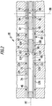
- the intermediate plate 30 comprises, as in Fig. 2 represented, as a whole by 60 designated central unit, which in turn is formed from a in a plane plane PE extending fluid guide plate 62, and arranged on both sides of the fluid guide plate cover plates 64, 66.
- the fluid guide plate 62 is provided with at least one fluid guide channel 72, which as open on both sides of the fluid guide plate 62 penetrating breakthrough in the plate plane PE runs that this formed by an opening 74 in the cover plate 64 inlet 46 connects to an opening formed by an opening 76 in the cover plate 66 outlet 48, so that the inlet 46 opposite the outlet 48 may be arranged offset in the direction of the plate plane PE.
- the fluid guide channel 72 is closed by the cover plates 64 and 66 and thus provide only the opening 74 and the opening 76 access to this fluid guide channel 72.
- the central unit 60 is preferably also designed so that it also forms the passage 42, which in turn is formed by an opening 82 in the fluid guide plate, an opening 82 aligned with the opening 84 in the cover plate 64 and one with the opening 82nd aligned breakthrough 86 in the cover plate 66, so that ultimately all openings 82, 84, 86 are arranged coaxially to a central axis 88, which is preferably perpendicular to the plate plane PE.
- an intermediate seal system 94 and 96 is provided, wherein the intermediate seal systems 94, 96 in the first embodiment have linearly extending sealing elements 102 which are arranged for example on one of the respective cover plate 64 and 66 facing surface 104 and 106 of the fluid guide plate 62 and with a corresponding surface 114 and 116 of the respective cover plate 64 and 66 cooperate to both the at least one fluid channel 72 around as well as to leave around the respective openings 82 and 84 and 86 around a fluid-tight seal.
- the intermediate sealing systems 94 and 96 are formed so that the sealing elements 102 are made of elastomeric material and are applied to the surfaces 104 and 106 and / or the surfaces 114 and 116.
- the elastomeric material of the sealing elements 102 is formed so that they cause an adhesive connection between the fluid guide plate 62 and the cover plates 64, 66 in addition to their height-elastic behavior.
- cover plates 64 and 66 in turn carry sealing systems 124, 126, which also have sealing elements 132 made of elastomeric material, on the channel sides 24 and 26 facing surfaces 134, 136 of the cover plates 64, 66 are arranged and a tight seal between the respective cover plates 64th and 66 and the respective channel side 24 and 26 of the corresponding housing part 12 and 14 effect.
- sealing elements 132 are preferably made of elastomeric material, which is applied, for example by screen printing on the surfaces 134 and 136 and fixed on this.
- the elastomeric material may expediently also be designed so that this can be brought in addition to its elastic elastic behavior with the channel sides 24, 26 in an adhesive or adhering to this connection, so that the elastomeric material in the assembled state of the control unit an adhesive connection between the respective cover plate 64 and 66 and the corresponding channel side 24 and 26 of the housing parts 12 and 14 creates.
- the intermediate plate 30 on the one hand creates a tight seal with the respective channel sides 24 and 26 and on the other hand, the intermediate plate 30 opens up the possibility to guide the pressure medium in the plane of the PE of the fluid guide plate 62 through the at least one fluid channel 72 and thus the constructive possibilities in Extend area of the housing parts 12, 14.
- an adhesive material having an adhesive or adhesive effect has the advantage that the elastomer material forms a firm connection both with the part of the intermediate plate carrying the elastomer material and with the part against which the elastomer material rests, and thus relative movements between the parts. especially in directions parallel to an extension plane of the intermediate plate, do not lead to friction of the elastomeric part on the elastomer and thus damaging the elastomeric layer over time, but to much less damaging shearing movements in the elastomeric layer, resulting in improved creep resistance the sealing elements made of elastomeric material can be reached.
- the elastomeric material for both the sealing members 103 and the sealing members 133 is formed to include a partially rubberized rubber material, the rubber material having a degree of polymerization ranging from 15% or more to 90% or less.
- the elastomeric material is a fluoropolymer rubber.
- the elastomeric material has an adhesive effect, which leads to a withdrawal tension of 0.1 kPa or more when the cover plate 64, 66 is removed from the fluid guide plate 62, the relevant area being the Total area extent is set over which extend the cover plate and the fluid guide plate in the overlapping region, that is, including also the surface area of the openings.
- the thickness of the layer of the elastomeric material is preferably in the range between 5 ⁇ m or more and 100 ⁇ m or less.
- the elastomer material can be applied over the entire surface, but it is also possible to apply elastomer material as a partially local layer.
- the fluid guide plate 62 is made of aluminum.
- cover plates 64 In addition to the cover plates 64, 66 may be made of aluminum or steel.
- the cover plates 64 and 66 have a rigidity whose deflection over a distance of 10 mm at a fluid pressure on these areally of 50 bar is 100 ⁇ m or less, preferably at this fluid pressure is 50 ⁇ m or less, more preferably 30 ⁇ m or less, and optimally 20 ⁇ m or less, even if the respective top plate 64, 66 is supported in a sealing member 132 Area is not supported directly by the fluid guide plate 62 to achieve a secure seal with the respective channel side 24, 26.
- cover plates 64, 66 opens up a sufficiently large number of degrees of freedom with regard to the formation of the fluid guide plate 62, in particular with fluid guide channels 72, without it being necessary, the cover plates 64, 66 respectively at the points provided with sealing elements 132 directly through the fluid guide plate or support at a small distance by the fluid guide plate 62.
- the cover plates 64 and 66 may have a thickness between 0.5 mm or more and 0.8 mm or less.
- the cover plates 64, 66 have a thickness ranging between 1 mm or more and 2 mm or less.
- the cover plates 64, 66 have a modulus of elasticity ranging between 70 GPa and 210 GPa.
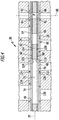
- FIG Fig. 3 In a second embodiment, shown in FIG Fig. 3 , those elements which are identical to those of the first embodiment are provided with the same reference numerals, so that with regard to the description of the same can be made in full content to the comments on the first embodiment.
- the cover plates 64 and 66 for example, in the area around the aperture 74 on material accumulations 138 which project beyond the surfaces 134 and 136 of the cover plates 64, 66, in these areas, a higher compression for the To achieve sealing elements 132 made of elastomeric material or to compensate for deflections of the cover plates 64, 66 in the direction of the channel sides 24 and 26 away.
- Such accumulations of material 138 are preferably formed backside neutral in the cover plates 64, 66, that is, that they do not affect the formation of the fluid guide plate 62 facing sides of the cover plates 64, 66.
- these accumulations of material 138 can be generated by forming the respective cover plates 64, 66, for example around the one opening, due to a flow of material, for example by upsetting or embossing.
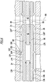
- FIG Fig. 4 In a third embodiment, shown in FIG Fig. 4 , those elements which are identical to those of the first embodiment are provided with the same reference numerals, so that with regard to the description of the same can be made in full to the comments on the first embodiment or the second embodiment.
- the intermediate seal systems 94 'and 96' are formed to include full-surface sealing elements 103 applied to the fluid guide plate 62 which provide a seal and an adhesive bond between the fluid guide plate 62 and the cover plates 64 and 66 produce.
- the sealing elements 103 each also extend around the fluid channel 72 as well as around the respective openings 82 and 84 and 86 and form a fluid-tight seal.
- FIG Fig. 5 In a fourth embodiment, shown in FIG Fig. 5 , those elements which are identical to those of the preceding embodiments, provided with the same reference numerals, so that with respect to the description of the same can be fully incorporated by reference to the statements to the preceding embodiments.
- the sealing systems 124 'and 126' also have no line-shaped sealing elements 132 but also planar sealing elements 133, which are arranged, for example, that they in the region of an overlap between the cover plates 64 and 66 and the channel sides 24 and 26 of the housing parts the cover plates 64 and 64 are applied and thus during assembly of the housing parts 12, 14 in an adhesive or adhesive connection with the channel sides 24, 26 can be brought, so that thereby a permanent connection between the channel sides 24 and 26 and the sealing elements 133 can be reached ,
- FIG Fig. 6 In a fifth embodiment, shown in FIG Fig. 6 , those elements which are identical to those of the preceding embodiments are provided with the same reference numerals, so that with regard to the description of the same can be made in full content to the comments on the above embodiments.
- the sealing systems 124 "and 126" are not formed from the sealing elements 132 of elastomeric material, but the sealing systems 124 "and 126" are formed by functional layers 144 and 146 which have sealing beads 152 at the locations to be sealed, which are in sealing positions 154, 156 are formed, wherein the sealing layers 154 and 156 are made for example of thin spring steel sheet.
- the sealing beads 152 are formed in the sealing layers 154, 156 such that they project beyond the sealing layers 154 and 156 in the direction of the channel sides 24 and 26 and thus with a beading crest 162 on the channel sides 24 and 26 of the housing parts 12 and 14 can be applied, while the beads 152 abut with their bead feet 164, 166 respectively on the surfaces 134 and 136 of the cover plates 64 and 66 respectively.
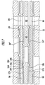
- FIG Fig. 7 a sixth embodiment of an intermediate plate according to the invention, shown in FIG Fig. 7 , Those parts that are identical to the above embodiments are provided with the same reference numerals, so that reference may be made to the full extent with regard to the description of the description.
- the intermediate seal systems 94 "and 96" are formed by functional layers 174 and 176, which have beads 182, the are formed in sealing layers 184 and 186, wherein the beads 182 are preferably formed so that a beading crest 192 facing the respective cover plates 64 and 66 and abuts against these, while the beads 182 with bead feet 194 and 196 on the fluid guide plate 62nd issue.
- both the intermediate sealing systems 94 "and 96" and the sealing systems 124 “and 126" are formed by metallic functional layers 144 and 146 and 174 and 176, respectively.
Description
Die Erfindung betrifft eine Zwischenplatte zur Montage zwischen Gehäuseteilen einer fluidbetriebenen Steuereinheit, insbesondere einer Getriebeeinheit, umfassend eine plattenförmig ausgebildete Zentraleinheit und beiderseits der Zentraleinheit jeweils ein Dichtungssystem zur Abdichtung zwischen der Zentraleinheit und dem dieser gegenüberliegenden Gehäuseteil, welches auf der jeweiligen Seite der Zentraleinheit angeordnete, um Durchbrüche herum verlaufende Dichtelemente umfasst.The invention relates to an intermediate plate for mounting between housing parts of a fluid-operated control unit, in particular a transmission unit comprising a plate-shaped central unit and on both sides of the central unit each have a sealing system for sealing between the central unit and the opposite housing part, which arranged on the respective side of the central unit to order Breakthroughs around extending sealing elements comprises.
Derartige Zwischenplatten sind aus dem Stand der Technik bekannt, wobei bei diesen lediglich eine Führung des Fluid quer, das heißt senkrecht, zur Zwischenplatte möglich ist. Ein Beispiel einer Zwischenplatte mit den Merkmalen des Oberbegriffs des Anspruchs 1 ist aus der
Bei diesen Zwischenplatten besteht jedoch die Notwendigkeit, das Fluid nicht lediglich quer durch die Zwischenplatte hindurch zu führen, sondern gegebenenfalls auch komplexere Wege für das Fluid zu realisieren.In these intermediate plates, however, there is a need not only to guide the fluid across the intermediate plate, but possibly also to realize more complex ways for the fluid.
Der Erfindung liegt daher die Aufgabe zugrunde, eine Zwischenplatte der gattungsgemäßen Art derart zu verbessern, dass diese eine komplexe Fluidführung erlaubt.The invention is therefore an object of the invention to improve an intermediate plate of the generic type such that it allows a complex fluid guide.
Diese Aufgabe wird bei einer Zwischenplatte der eingangs beschriebenen Art erfindungsgemäß dadurch gelöst, dass die Zentraleinheit eine sich in einer Plattenebene erstreckende und mindestens einen in der Plattenebene verlaufenden Fluidführungskanal aufweisende Fluidführungsplatte sowie beiderseits der Fluidführungsplatte angeordnete und Durchbrüche als Zugänge zu dem mindestens einen Fluidführungskanal aufweisende Deckplatten umfasst, dass zwischen der jeweiligen Deckplatte und der Fluidführungsplatte ein den mindestens einen Fluidführungskanal abdichtendes Zwischendichtungssystem vorgesehen ist und dass die jeweilige Deckplatte das jeweilige Dichtungssystem zur Abdichtung zwischen der Zentraleinheit und dem jeweiligen Gehäuseteil trägt.This object is achieved in an intermediate plate of the type described above according to the invention that the central unit comprises a extending in a plate plane and at least one extending in the plane of fluid guide channel fluid guide plate and both sides of the fluid guide plate arranged and openings as access to the at least one fluid guide channel having cover plates in that between the respective cover plate and the fluid guide plate a the at least one fluid guide channel sealing intermediate seal system is provided and that the respective cover plate carries the respective sealing system for sealing between the central unit and the respective housing part.
Der Vorteil der erfindungsgemäßen Lösung ist darin zu sehen, dass durch die Fluidführungsplatte die Möglichkeit besteht in der Plattenebene komplexe Wege für das Fluid zu realisieren, wobei diese Wege sich durch die beiden beiderseits der Fluidführungsplatte angeordneten Deckplatten abdecken und somit abdichten lassen, und wobei insbesondere die Deckplatten eine stabile Basis für die Abdichtung zu den Gehäuseteilen hin ermöglichen.The advantage of the solution according to the invention is to be seen in the fact that the fluid guide plate makes it possible to realize complex paths for the fluid in the plane of the plate, whereby these paths can be covered by the two cover plates arranged on both sides of the fluid guide plate and thus sealed, and in particular the Cover plates provide a stable base for the sealing towards the housing parts out.
Vorzugsweise verhält sich dabei das Zwischendichtungssystem höhenelastisch, um Abstandstoleranzen zwischen der Fluidführungsplatte und den Deckplatten abzudichten.The intermediate sealing system preferably behaves in a height-elastic manner in order to seal distance tolerances between the fluid guiding plate and the cover plates.
Um eine derartige Zentraleinheit möglichst kostengünstig und auch hinsichtlich ihrer Druckfestigkeit dauerhaft herstellen zu können, ist vorzugsweise vorgesehen, dass das Zwischendichtungselement zusätzlich zur Abdichtungswirkung die Fluidführungsplatte mit der jeweiligen Deckplatte durch eine Klebewirkung verbindet.In order to be able to produce such a central unit as cost-effectively as possible and also with regard to its compressive strength, it is preferably provided that the intermediate sealing element, in addition to the sealing effect, connects the fluid guiding plate to the respective cover plate by an adhesive effect.
Eine derartige Klebewirkung hat den großen Vorteil, dass damit eine dauerhafte Verbindung zwischen der Fluidführungsplatte und den Deckplatten realisierbar ist, die einerseits die notwendige Stabilität verleiht und andererseits die erforderliche Dichtigkeit.Such an adhesive effect has the great advantage that thus a permanent connection between the fluid guide plate and the cover plates can be realized, on the one hand gives the necessary stability and on the other hand, the required tightness.
Dabei ist insbesondere vorgesehen, dass das Zwischendichtungselement zusätzlich zu der Klebewirkung sich höhenelastisch verhält.In this case, it is provided in particular that the intermediate sealing element behaves in a height-elastic manner in addition to the adhesive effect.
Ferner ist zweckmäßigerweise vorgesehen, dass Dichtelemente des Zwischendichtungssystems sowohl mit der Fluidführungsplatte als auch mit der jeweiligen Deckplatte klebend zusammenwirken und somit die Dichtung und die klebende Verbindung zwischen der Fluidführungsplatte und den Deckplatten durch ein Element realisierbar ist.Further, it is expediently provided that sealing elements of the intermediate sealing system cooperate adhesively both with the fluid guide plate and with the respective cover plate and thus the seal and the adhesive connection between the fluid guide plate and the cover plates can be realized by an element.
Der mindestens eine Fluidführungskanal ist insbesondere als einseitig offene Nut oder beidseitig offener die Fluidführungsplatte durchsetzender Durchbruch ausgebildet, der durch die Deckplatten verschlossen ist und von einem Zugang in mindestens einer der Deckplatten zu einem weiteren Zugang in mindestens einer der Deckplatten verläuft.The at least one fluid guide channel is in particular formed as a groove open on one side or open on both sides breakthrough which is closed by the cover plates and extends from an access in at least one of the cover plates to a further access in at least one of the cover plates.
Vorzugsweise ist vorgesehen, dass Dichtelemente des Zwischendichtungssystems in einem Abstand von 2 mm oder weniger von Rändern des mindestens einen Fluidführungskanals verlaufen, um einen möglichst kompakten Aufbau der Zentraleinheit realisieren zu können.It is preferably provided that sealing elements of the intermediate sealing system extend at a distance of 2 mm or less from edges of the at least one fluid guiding channel, in order to be able to realize the most compact possible construction of the central unit.
Ferner ist vorgesehen, dass das Zwischendichtungssystem um den mindestens einen Fluidführungskanal in der Fluidführungsplatte herum verlaufende Dichtelemente umfasst.It is further provided that the intermediate seal system comprises sealing elements extending around the at least one fluid guide channel in the fluid guide plate.
Ferner sieht eine zweckmäßige Lösung vor, dass die Dichtelemente um den mindestens einen Fluidführungskanal in der Fluidführungsplatte und um die Durchbrüche in den Deckplatten und/oder der Fluidführungsplatte herum verlaufen.Furthermore, an expedient solution provides that the sealing elements run around the at least one fluid guide channel in the fluid guide plate and around the openings in the cover plates and / or the fluid guide plate.
Die Dichtelemente können dabei als flächenhafte Dichtungen ausgebildet sein oder als Liniendichtungen.The sealing elements may be formed as areal seals or as line seals.
Mit Liniendichtungen ist eine besonders wirksame Realisierung einer Abdichtung möglich.With line seals a particularly effective realization of a seal is possible.
Die Abdichtung durch das Zwischendichtungssystem kann beispielsweise durch eine Klebemasse realisiert werden.The seal by the intermediate sealing system can be realized for example by an adhesive.
Eine besonders günstige Lösung sieht vor, dass das Zwischendichtungssystem zwischen der Fluidführungsplatte und der jeweiligen Deckplatte angeordnete Dichtelemente aus Elastomermaterial umfasst.A particularly favorable solution provides that the intermediate sealing system comprises between the fluid guide plate and the respective cover plate arranged sealing elements made of elastomeric material.
Besonders günstig ist es, wenn das Elastomermaterial auch eine Klebewirkung hat und somit die Fluidführungsplatte mit der jeweiligen Deckplatte zusätzlich zum Abdichten auch noch klebend verbindet.It is particularly favorable if the elastomer material also has an adhesive effect and thus also connects the fluid guide plate to the respective cover plate in an adhesive manner in addition to sealing.
Das Vorsehen eines haftend oder klebend wirkenden Elastomermaterials hat außerdem den Vorteil, dass das Elastomermaterial sowohl mit dem das Elastomermaterial tragenden Teil der Zwischenplatte als auch mit dem anderen Teil der Zwischenplatte im zusammengebauten Zustand eines feste Verbindung eingeht und somit Relativbewegungen zwischen den Teilen, insbesondere in Richtungen parallel zu einer Erstreckungsebene der Zwischenplatte, nicht zu Reibung des an dem Elastomer anliegenden Teils auf dem Elastomer und somit zu einer Beschädigung der Elastomerschicht im Laufe der Zeit führen, sondern zu weit weniger schädlichen Scherbewegungen in der Elastomerschicht, so dass eine verbesserte Dauerstandfestigkeit der Dichtelemente aus Elastomermaterial erreichbar ist.The provision of an adhesive or adhesive elastomeric material also has the advantage that the elastomer material enters both with the elastomeric material-carrying part of the intermediate plate and with the other part of the intermediate plate in the assembled state of a firm connection and thus relative movements between the parts, in particular in directions parallel to an extension plane of the intermediate plate, do not lead to friction of the elastomer on the part on the elastomer and thus to damage the elastomer layer over time, but to far less damaging shearing movements in the elastomer layer, so that an improved fatigue strength of the sealing elements Elastomer material is achievable.
Das Elastomermaterial könnte zum Beispiel ein Silikonmaterial sein.The elastomeric material could be, for example, a silicone material.
Besonders günstig ist es jedoch, wenn das Elastomermaterial ein teilpolmerisiertes Kautschukmaterial umfasst, das durch die Teilpolymerisation auch noch eine klebende Wirkung hat.However, it is particularly favorable if the elastomer material comprises a partially polymerized rubber material which also has an adhesive effect as a result of the partial polymerization.
Zweckmäßigerweise weist dabei das Kautschukmaterial einen Polymerisationsgrad auf, der im Bereich zwischen 15 % oder mehr und 90 % oder weniger liegt.Conveniently, the rubber material has a degree of polymerization ranging from 15% or more to 90% or less.
Insbesondere ist das Elastomermaterial ein Fluorpolymerkautschuk.In particular, the elastomeric material is a fluoropolymer rubber.
Hinsichtlich der Schichtdicken wurden dabei ebenfalls noch keine weiteren Angaben gemacht.With regard to the layer thicknesses, no further details were given.
Vorzugsweise weist die Schicht aus Elastomermaterial eine Dicke von 5 µm oder mehr, besser 10 µm oder mehr, noch besser 15 µm oder mehr, auf.Preferably, the layer of elastomeric material has a thickness of 5 microns or more, more preferably 10 microns or more, more preferably 15 microns or more.
Die Dicke ist zweckmäßigerweise auf 100 µm oder weniger, besser 50 µm oder weniger, noch besser 30 µm oder weniger, begrenzt.The thickness is suitably limited to 100 μm or less, more preferably 50 μm or less, more preferably 30 μm or less.
Das Elastomermaterial kann vollflächig aufgetragen werden.The elastomeric material can be applied over the entire surface.
Das Elastomermaterial kann aber auch als partiell lokale Schicht aufgetragen werden.The elastomer material can also be applied as a partially local layer.
Besonders günstig ist es, wenn das Elastomermaterial eine Klebewirkung aufweist, die bei Entfernung der Deckplatte von der Fluidführungsplatte zu einer Abzugsspannung von 0,1 kPa oder mehr führt, wobei als relevante Fläche die Gesamtfläche angesetzt ist, über die sich die Deckplatte und die Fluidführungsplatte in ihrem Überlappungsbereich erstrecken.It is particularly advantageous if the elastomer material has an adhesive effect, which leads to a withdrawal tension of 0.1 kPa or more when the cover plate is removed from the fluid guide plate, the relevant area being the total area over which the cover plate and the fluid guide plate are attached extend their overlap area.
Ein derartiger Auftrag des Elastomermaterials kann in unterschiedlichster Weise erfolgen.Such an order of the elastomeric material can be done in a variety of ways.
Eine günstige Lösung sieht vor, dass das Elastomermaterial auf der jeweiligen Platte durch Walzen oder durch Siebdruck aufgetragen ist.A favorable solution provides that the elastomeric material is applied to the respective plate by rolling or by screen printing.
Ein derartiges Auftragen des Elastomermaterials ermöglicht es in besonders einfacher Weise das Dichtelement herzustellen.Such application of the elastomeric material makes it possible to produce the sealing element in a particularly simple manner.
Ferner ist vorzugsweise vorgesehen, dass das Zwischendichtungssystem als Dichtelement auf der jeweiligen Platte, das heißt der Fluidführungsplatte und/oder den Deckplatten, angeordnete linienförmige Elastomerstreifen umfasst.Furthermore, it is preferably provided that the intermediate sealing system as a sealing element on the respective plate, that is, the fluid guide plate and / or the cover plates, arranged line-shaped elastomeric strip comprises.
Alternativ dazu sieht eine vorteilhafte Lösung vor, dass zwischen den Deckplatten und der Fluidführungsplatte die Zwischendichtungssysteme bildende Dichtlagen mit eingeformten Dichtsicken als Dichtelemente angeordnet sind.Alternatively, an advantageous solution provides that between the cover plates and the fluid guide plate, the intermediate sealing systems forming sealing layers are arranged with molded sealing beads as sealing elements.
Diese Lösung erlaubt es, insbesondere aufgrund der vorteilhaften Höhenelastizität der Dichtsicken, einen dichten Abschluss zwischen der Fluidführungsplatte und den Deckplatten zu erreichen, wobei gegebenenfalls auch die Dichtsicken der Dichtelemente mit Elastomermaterial zur Mikroabdichtung beschichtet sein können.This solution makes it possible, in particular due to the advantageous height elasticity of the sealing beads, to achieve a tight seal between the fluid guide plate and the cover plates, where appropriate, the sealing beads of the sealing elements may be coated with elastomeric material for micro-sealing.
Im Zusammenhang mit der Erläuterung der erfindungsgemäßen Lösung wurde bislang nicht näher auf die Eigenschaften der Deckplatten und der Fluidführungsplatten eingegangen.In connection with the explanation of the solution according to the invention has not been discussed in detail on the properties of the cover plates and the fluid guide plates.
Insbesondere dann, wenn komplexen Fluidführungskanäle durch einseitig offene Nuten oder beidseitig offene Durchbrüche in der Fluidführungsplatte realisiert werden sollen, besteht die Notwendigkeit, dass die Deckplatten eine ausreichende Steifigkeit aufweisen, um wiederum für das Dichtungssystem eine ausreichende Dichtpressung zur Verfügung stellen zu können.In particular, when complex fluid guide channels are to be realized by unilaterally open grooves or openings open in the fluid guide plate on both sides, there is a need that the cover plates have sufficient rigidity, in turn, to be able to provide sufficient sealing pressure for the sealing system.
Aus diesem Grund ist vorzugsweise vorgesehen, dass die Deckplatten eine Steifigkeit aufweisen, deren Durchbiegung über eine Distanz von 10 mm bei einem auf diesen flächenhaft lastenden Fluiddruck von 50 bar 100 µm oder weniger beträgt, vorzugsweise 50 µm oder weniger beträgt, noch besser 30 µm oder weniger beträgt und im Optimalfall 20 µm oder weniger beträgt.For this reason, it is preferably provided that the cover plates have a rigidity whose deflection over a distance of 10 mm at a surface pressure of 50 bar of fluid pressure of 100 microns or less, preferably 50 microns or less, more preferably 30 microns or is less and in the optimal case 20 microns or less.
Somit kann für die Auslegung des Dichtungssystems zwischen der Zentraleinheit und dem jeweiligen Gehäuseteil von definierten Verhältnissen zur Abstützung des Dichtungssystems durch die Zentraleinheit ausgegangen werden.Thus, for the design of the sealing system between the central unit and the respective housing part of defined ratios for supporting the sealing system can be assumed by the central unit.
Eine derartige Steifigkeit der Deckplatten lässt sich in einfacher Weise dadurch realisieren, dass die Deckplatten aus Stahl hergestellt sind.Such rigidity of the cover plates can be realized in a simple manner by the fact that the cover plates are made of steel.
Vorzugsweise haben dabei die Deckplatten eine Dicke im Bereich zwischen 0,5 mm oder mehr und 2 mm oder weniger, um eine ausreichende Stabilität zu haben.Preferably, the cover plates have a thickness in the range between 0.5 mm or more and 2 mm or less in order to have sufficient stability.
Alternativ dazu ist vorgesehen, dass die Deckplatten aus Aluminium oder Aluminiumlegierungen hergestellt sind.Alternatively, it is envisaged that the cover plates are made of aluminum or aluminum alloys.
In diesem Fall ist zweckmäßigerweise vorgesehen, dass die Deckplatten eine Dicke im Bereich zwischen 1 mm oder mehr und 2 mm oder weniger aufweisen.In this case, it is expediently provided that the cover plates have a thickness in the range between 1 mm or more and 2 mm or less.
Ferner ist vorzugsweise ein Elastizitätsmodul der Deckplatten vorgegeben.Furthermore, a modulus of elasticity of the cover plates is preferably predetermined.
Zweckmäßigerweise liegt der Elastizitätsmodul der Deckplatten im Bereich von 70 GPa oder mehr und 210 GPa oder weniger.Conveniently, the modulus of elasticity of the cover plates is in the range of 70 GPa or more and 210 GPa or less.
Um Deformationen sowohl der Gehäuseteile als auch Zentraleinheit ausgleichen zu können, ist vorzugsweise vorgesehen, dass die Deckplatten zur Ausbildung des Dichtungssystems auf ihrer dem jeweiligen Gehäuseteil zugewandten Seite Materialanhäufungen aufweisen.In order to compensate for deformations of both the housing parts and the central unit, it is preferably provided that the cover plates for forming the sealing system on its side facing the respective housing part have material accumulations.
Derartige Materialanhäufungen sind vorzugsweise so ausgebildet, dass sie eine Höhenprofilierung darstellen, wobei die Höhenprofilierung, beispielsweise entsprechend einem Abstand zwischen Verschraubungspunkten, variieren kann und somit nicht konstant sein muss.Such material accumulations are preferably formed so that they represent a height profiling, wherein the height profiling, for example, according to a distance between Verschraubungspunkten, may vary and thus need not be constant.
Damit lassen sich Deformationen sowohl der Gehäuseteile als auch der Zentraleinheit, insbesondere der Deckplatten vorab kompensieren.This allows deformations of both the housing parts and the central unit, in particular the cover plates compensate in advance.
Vorzugsweise sind dabei die Materialanhäufungen rückseitenneutral ausgebildet.Preferably, the material accumulations are formed back neutral.
Besonders günstig ist es, wenn die Materialanhäufungen durch Umformungen in den Deckplatten entstanden sind, das heißt, dass derartige Umformungen Stauchungen oder Prägungen der Deckplatten sein können.It is particularly favorable if the material accumulations have been formed by deformations in the cover plates, that is to say that such transformations can be upsetting or embossing of the cover plates.
Hinsichtlich des Dichtungssystems zwischen der Zentraleinheit und den Gehäuseteilen wurden bislang keine näheren Angaben gemacht.With regard to the sealing system between the central unit and the housing parts so far no details have been made.
So sieht eine vorteilhafte Lösung vor, dass das Dichtungssystem als Dichtelement auf der jeweiligen Deckplatte angeordnetes Elastomermaterial aufweist.Thus, an advantageous solution provides that the sealing system has a sealing element arranged on the respective cover plate elastomeric material.
Das heißt, dass dieses Elastomermaterial auf einer plan verlaufenden Oberfläche der jeweiligen Deckplatte angeordnet sein kann.This means that this elastomeric material can be arranged on a plane running surface of the respective cover plate.
Es besteht aber auch die Möglichkeit, das Dichtelement auf einer der vorstehend beschriebenen Materialanhäufungen anzuordnen, so dass die Möglichkeit besteht, Durchbiegungen der Gehäuseteile und der Zentraleinheit zu kompensieren.But it is also possible to arrange the sealing element on one of the material accumulations described above, so that there is the possibility to compensate for deflections of the housing parts and the central unit.
Ein derartiges Elastomermaterial lässt sich in unterschiedlichster Weise auftragen, beispielsweise flächenhaft oder strukturiert.Such an elastomeric material can be applied in a wide variety of ways, for example planar or structured.
Eine besonders kostengünstige Lösung sieht vor, dass das Elastomermaterial auf die jeweilige Deckplatte durch Walzen oder Siebdruck aufgetragen ist.A particularly cost-effective solution provides that the elastomeric material is applied to the respective cover plate by rolling or screen printing.
Insbesondere lässt sich das Elastomermaterial dadurch in einfacher Weise als Dichtelement auftragen, wenn das Dichtungssystem als Dichtelement auf der Deckplatte angeordnete Flächen und/oder linienförmige Streifen aus Elastomermaterial umfasst.In particular, the elastomer material can thereby be applied in a simple manner as a sealing element, if the sealing system comprises surfaces arranged on the cover plate as a sealing element and / or linear strips of elastomer material.
Das Elastomermaterial kann dabei in gleicher Weise ausgebildet sein und dieselbe Klebewirkung sowie dieselbe Dicke aufweisen, wie im Zusammenhang mit dem Elastomermaterial für das Zwischendichtungssystem beschrieben.The elastomeric material may be formed in the same way and have the same adhesive effect and the same thickness, as described in connection with the elastomeric material for the intermediate sealing system.
Alternativ oder ergänzend zum Vorsehen von Elastomermaterial sieht eine andere Lösung vor, dass auf den Deckplatten das Dichtungssystem bildende Dichtlagen mit eingeformten Dichtsicken als Dichtelemente angeordnet sind.As an alternative or in addition to the provision of elastomer material, another solution provides that sealing layers forming the sealing system with molded-on sealing beads are arranged as sealing elements on the cover plates.
Ein Dichtungssystem mit Dichtsicken schafft die Möglichkeit, in vorteilhafter Weise Veränderungen von Durchbiegungen der Gehäuseteile und/oder der Zentraleinheit elastisch zu kompensieren.A sealing system with sealing beads creates the possibility of elastically compensating for changes in deflections of the housing parts and / or the central unit in an advantageous manner.
Dabei können derartige Dichtsicken auch mit Elastomermaterial zur Mikroabdichtung kombiniert werden.Such sealing beads can also be combined with elastomeric material for micro-sealing.
Derartige Dichtsicken können aber auch mit Materialanhäufungen zum Ausgleich von beispielsweise signifikanten Durchbiegungen der Gehäuseteile oder der Zentraleinheit kombiniert werden.But such dense beads can also be combined with accumulations of material to compensate for example significant deflections of the housing parts or the central unit.
Ferner ist erfindungsgemäß vorgesehen, dass die Deckplatten und die Fluidführungsplatte jeweils aus Materialien hergestellt sind, deren Wärmeausdehnungskoeffizienten sich um maximal 20%, noch besser um maximal 10%, unterscheiden.Further, the invention provides that the cover plates and the fluid guide plate are each made of materials whose coefficients of thermal expansion differ by a maximum of 20%, even better by a maximum of 10%.
Eine derartige Materialauswahl von Deckplatten und Fluidführungsplatten hat den Vorteil, dass sich damit in einfacher Weise die Abdichtung zwischen diesen beiden realisieren lässt, ohne dass signifikante Probleme durch die unterschiedliche Wärmeausdehnung auftreten.Such a material selection of cover plates and fluid guide plates has the advantage that it can be realized in a simple manner, the seal between these two without significant problems occur due to the different thermal expansion.
Besonders einfach ist es, wenn die Deckplatten und die Fluidführungsplatte aus identischen Materialien hergestellt sind.It is particularly simple when the cover plates and the fluid guide plate are made of identical materials.
Im Hinblick auf eine Leichtbauweise vorzugsweise vorgesehen, dass die Deckplatten und die Fluidführungsplatte aus Aluminium hergestellt sind.With regard to a lightweight construction, it is preferably provided that the cover plates and the fluid guide plate are made of aluminum.
Weitere Merkmale und Vorteile der Erfindung sind Gegenstand der nachfolgenden Beschreibung sowie der zeichnerischen Darstellung einiger Ausführungsbeispiele.Further features and advantages of the invention are the subject of the following description and the drawings of some embodiments.
In der Zeichnung zeigen:
- Fig. 1
- eine schematische Explosionsdarstellung zweier bereichsweise aufgebrochen dargestellte Gehäuseteile einer Steuereinheit und eine schematische Darstellung einer Zwischenplatte zwischen diesen Gehäuseteilen;
- Fig. 2
- eine ausschnittsweise vergrößerte Darstellung der Gehäuseteile, wie sie in dem montierten Zustand der Steuereinheit an einem ersten Ausführungsbeispiel der Zwischenplatte anliegen;
- Fig. 3
- eine ausschnittsweise vergrößerte Darstellung der Gehäuseteile, wie sie in dem montierten Zustand der Steuereinheit an einem zweiten Ausführungsbeispiel der Zwischenplatte anliegen;
- Fig. 4
- eine ausschnittsweise vergrößerte Darstellung der Gehäuseteile, wie sie in dem montierten Zustand der Steuereinheit an einem dritten Ausführungsbeispiel der Zwischenplatte anliegen;
- Fig. 5
- eine ausschnittsweise vergrößerte Darstellung der Gehäuseteile, wie sie in dem montierten Zustand der Steuereinheit an einem vierten Ausführungsbeispiel der Zwischenplatte anliegen;
- Fig. 6
- eine ausschnittsweise vergrößerte Darstellung der Gehäuseteile, wie sie in dem montierten Zustand der Steuereinheit an einem fünften Ausführungsbeispiel der Zwischenplatte anliegen und
- Fig. 7
- eine ausschnittsweise vergrößerte Darstellung der Gehäuseteile, wie sie in dem montierten Zustand der Steuereinheit an einem sechsten Ausführungsbeispiel der Zwischenplatte anliegen.
- Fig. 1
- a schematic exploded view of two partially broken housing parts of a control unit and a schematic representation of an intermediate plate between these housing parts;
- Fig. 2
- a fragmentary enlarged view of the housing parts, as they rest in the mounted state of the control unit to a first embodiment of the intermediate plate;
- Fig. 3
- a fragmentary enlarged view of the housing parts, as they rest in the assembled state of the control unit to a second embodiment of the intermediate plate;
- Fig. 4
- a fragmentary enlarged view of the housing parts, as in the mounted state of the control unit abut a third embodiment of the intermediate plate;
- Fig. 5
- a fragmentary enlarged view of the housing parts, as they rest in the mounted state of the control unit to a fourth embodiment of the intermediate plate;
- Fig. 6
- a fragmentary enlarged view of the housing parts, as in the mounted state of the control unit to a fifth embodiment of the intermediate plate and abut
- Fig. 7
- a fragmentary enlarged view of the housing parts, as they rest in the mounted state of the control unit to a sixth embodiment of the intermediate plate.
Eine in
Die beiden Gehäuseteile 12, 14 weisen einander zugewandte Kanalseiten 24 und 26 auf, welche so ausgebildet sind, dass das Fluid von dem einen Gehäuseteil 12, 14 in das jeweils andere Gehäuseteil 14, 12 übertreten kann.The two
Zwischen diesen Kanalseiten 24 und 26 der Gehäuseteile 12, 14 ist eine als Ganzes mit 30 bezeichnete Zwischenplatte eingesetzt, die an der Kanalseite 24 des ersten Gehäuseteils 12 mit einer ersten Seite 32 und an der Kanalseite 26 des zweiten Gehäuseteils 14 mit einer zweiten Seite 34 anliegt und jeweils mit den Kanalseiten 24, 26 dicht abschließt, wobei in der Zwischenplatte 30 Durchlässe, beispielsweise die Durchlässe 42, 44, und eventuell noch weitere Durchlässe, vorgesehen sind, durch welche ein Übertreten des Fluids von einem Gehäuseteil 12, 14 in das andere Gehäuseteil 14, 12 erfolgt.Between these
Dabei ermöglichen einige der Durchlässe, beispielsweise der Durchlass 42, ein ungehindertes Übertreten des Fluids von dem einen Gehäuseteil 12, 14 in das jeweils andere Gehäuseteil 14, 12, ergänzend dazu dienen einige der Durchlässe, beispielsweise der Durchlass 44, als Drossel für das vom einen Gehäuseteil 12, 14 in das andere Gehäuseteil 14, 12 übertretende Fluid, wobei durch einen derartigen Durchlass eine gezielte anpassbare Drosselwirkung zur Steuerung von Abläufen, insbesondere zeitlichen Abläufen bei Schaltvorgängen, erreicht werden kann.In this case, some of the passages, for example, the
Ferner dient die Zwischenplatte 30 auch dazu, das Fluid über einen der Kanalseite 24 zugewandte Einlass 46 aufzunehmen und in einer Ebene der Zwischenplatte 30 über eine Distanz zu führen und an einem der Kanalseite 26 zugewandten Auslass 48 austreten zu lassen.Furthermore, the
Die Zwischenplatte 30 umfasst, wie in
Die Fluidführungsplatte 62 ist mit mindestens einem Fluidführungskanal 72 versehen, welcher als beiderseits offener die Fluidführungsplatte 62 durchsetzender Durchbruch derart in der Plattenebene PE verläuft, dass dieser den durch einen Durchbruch 74 in der Deckplatte 64 gebildeten Einlass 46 mit einem durch einen Durchbruch 76 in der Deckplatte 66 gebildeten Auslass 48 verbindet, so dass der Einlass 46 gegenüber dem Auslass 48 in Richtung der Plattenebene PE versetzt angeordnet sein kann.The
Dabei ist der Fluidführungskanal 72 durch die Deckplatten 64 und 66 verschlossen und somit stellen lediglich der Durchbruch 74 und der Durchbruch 76 Zugänge zu diesem Fluidführungskanal 72 dar.In this case, the
Ferner ist vorzugsweise die Zentraleinheit 60 aber auch so ausgebildet, dass sie ebenfalls auch den Durchlass 42 bildet, der seinerseits gebildet ist durch einen Durchbruch 82 in der Fluidführungsplatte, einen mit dem Durchbruch 82 fluchtenden Durchbruch 84 in der Deckplatte 64 sowie einen mit dem Durchbruch 82 fluchtenden Durchbruch 86 in der Deckplatte 66, so dass letztlich alle Durchbrüche 82, 84, 86 koaxial zu einer Mittelachse 88 angeordnet sind, die vorzugsweise senkrecht zur Plattenebene PE verläuft.Furthermore, the
Zur Abdichtung zwischen der Fluidführungsplatte 62 sowie den beiden Deckplatten 64 und 66 ist jeweils zwischen der Fluidführungsplatte 62 und der jeweiligen Deckplatte 64 bzw. 66 ein Zwischendichtungssystem 94 bzw. 96 vorgesehen, wobei die Zwischendichtungssysteme 94, 96 bei dem ersten Ausführungsbeispiel linienförmig verlaufende Dichtelemente 102 aufweisen, die beispielsweise auf einer der jeweiligen Deckplatte 64 bzw. 66 zugewandten Oberfläche 104 bzw. 106 der Fluidführungsplatte 62 angeordnet sind und mit einer korrespondierenden Oberfläche 114 bzw. 116 der jeweiligen Deckplatte 64 bzw. 66 zusammenwirken, um sowohl um den mindestens einen Fluidkanal 72 herum als auch um die jeweiligen Durchbrüche 82 bzw. 84 und 86 herum einen fluiddichten Abschluss zu lassen.For sealing between the
Bei dem ersten, in
Dabei ist vorzugsweise das Elastomermaterial der Dichtungselemente 102 so ausgebildet, dass diese zusätzlich zu ihrem höhenelastischen Verhalten eine klebende Verbindung zwischen der Fluidführungsplatte 62 und den Deckplatten 64, 66 bewirken.In this case, preferably, the elastomeric material of the sealing
Ferner tragen die Deckplatten 64 und 66 ihrerseits Dichtungssysteme 124, 126, welche ebenfalls Dichtelemente 132 aus Elastomermaterial aufweisen, die auf den Kanalseiten 24 bzw. 26 zugewandten Oberflächen 134, 136 der Deckplatten 64, 66 angeordnet sind und einen dichten Abschluss zwischen den jeweiligen Deckplatten 64 und 66 sowie der jeweiligen Kanalseite 24 bzw. 26 des entsprechenden Gehäuseteils 12 bzw. 14 bewirken.Furthermore, the
Auch diese Dichtelemente 132 sind vorzugsweise aus Elastomermaterial hergestellt, welches beispielsweise im Siebdruckverfahren auf die Oberflächen 134 bzw. 136 aufgetragen und auf diesen fixiert ist.These sealing
Das Elastomermaterial kann dabei zweckmäßigerweise ebenfalls so ausgebildet sein, dass dieses zusätzlich zu seinem höhenelastischen Verhalten mit den Kanalseiten 24, 26 in eine an diesen haftende oder an diesen klebende Verbindung bringbar ist, so dass das Elastomermaterial im montierten Zustand der Steuereinheit eine klebende Verbindung zwischen der jeweiligen Deckplatte 64 bzw. 66 und der entsprechenden Kanalseite 24 bzw. 26 der Gehäuseteile 12 bzw. 14 schafft.The elastomeric material may expediently also be designed so that this can be brought in addition to its elastic elastic behavior with the channel sides 24, 26 in an adhesive or adhering to this connection, so that the elastomeric material in the assembled state of the control unit an adhesive connection between the
Damit schafft die erfindungsgemäße Zwischenplatte 30 einerseits einen dichten Abschluss mit den jeweiligen Kanalseiten 24 bzw. 26 und andererseits eröffnet die Zwischenplatte 30 die Möglichkeit, das Druckmittel in der Plattenebene PE der Fluidführungsplatte 62 durch den mindestens einen Fluidkanal 72 zu führen und somit die konstruktiven Möglichkeiten im Bereich der Gehäuseteile 12, 14 zu erweitern.Thus, the
Das Vorsehen eines haftend oder klebend wirkenden Elastomermaterials hat den Vorteil, dass das Elastomermaterial sowohl mit dem das Elastomermaterial tragenden Teil der Zwischenplatte als auch mit dem Teil, an dem das Elastomermaterial anliegt, im montierten Zustand eine feste Verbindung eingeht und somit Relativbewegungen zwischen den Teilen, insbesondere in Richtungen parallel zu einer Erstreckungsebene der Zwischenplatte, nicht zu Reibung des an dem Elastomer anliegenden Teils auf dem Elastomer und somit zu einer Beschädigung der Elastomerschicht im Laufe der Zeit führen, sondern zu weit weniger schädlichen Scherbewegungen in der Elastomerschicht, so dass eine verbesserte Dauerstandfestigkeit der Dichtelemente aus Elastomermaterial erreichbar ist.The provision of an adhesive material having an adhesive or adhesive effect has the advantage that the elastomer material forms a firm connection both with the part of the intermediate plate carrying the elastomer material and with the part against which the elastomer material rests, and thus relative movements between the parts. especially in directions parallel to an extension plane of the intermediate plate, do not lead to friction of the elastomeric part on the elastomer and thus damaging the elastomeric layer over time, but to much less damaging shearing movements in the elastomeric layer, resulting in improved creep resistance the sealing elements made of elastomeric material can be reached.
Insbesondere ist das Elastomermaterial sowohl für die Dichtungselemente 103 als auch für die Dichtungselemente 133 so ausgebildet, dass es ein teilpolmerisiertes Kautschukmaterial umfasst, wobei das Kautschukmaterial einen Polymerisationsgrad aufweist, der im Bereich zwischen 15% oder mehr und 90 % oder weniger liegt.Specifically, the elastomeric material for both the sealing
Vorzugsweise ist das Elastomermaterial ein Fluorpolymerkautschuk.Preferably, the elastomeric material is a fluoropolymer rubber.
Beispielsweise weist das Elastomermaterial eine Klebewirkung auf, die bei Entfernung der Deckplatte 64, 66 von der Fluidführungsplatte 62 zu einer Abzugsspannung von 0,1 kPa oder mehr führt, wobei als relevante Fläche die Gesamtflächenausdehnung angesetzt ist, über die die Deckplatte und die Fluidführungsplatte im Überlappungsbereich erstrecken, das heißt, mit Einbeziehung auch der Flächenausdehnung der Durchbrüche.For example, the elastomeric material has an adhesive effect, which leads to a withdrawal tension of 0.1 kPa or more when the
Die Dicke der Schicht des Elastomermaterials liegt vorzugsweise im Bereich zwischen 5 µm oder mehr und 100 µm oder weniger.The thickness of the layer of the elastomeric material is preferably in the range between 5 μm or more and 100 μm or less.
Das Elastomermaterial kann vollflächig aufgetragen werden, es ist aber auch möglich, Elastomermaterial als partiell lokale Schicht aufzutragen.The elastomer material can be applied over the entire surface, but it is also possible to apply elastomer material as a partially local layer.
Hinsichtlich der Ausbildung der Fluidführungsplatte 62 und der Deckplatten 64, 66 wurden bislang keine näheren Angaben gemacht.With regard to the design of the
So ist vorzugsweise vorgesehen, dass die Fluidführungsplatte 62 aus Aluminium hergestellt ist.Thus, it is preferably provided that the
Ergänzend dazu können auch die Deckplatten 64, 66 aus Aluminium oder Stahl hergestellt sein.In addition to the
Wesentlich ist es jedoch für eine zuverlässige Abdichtung zwischen den jeweiligen Deckplatten 64 und 66 und den jeweiligen Kanalseiten 24 und 26 der Gehäuseteile 12, 14, dass die Deckplatten eine Steifigkeit aufweisen, deren Durchbiegung über eine Distanz von 10 mm bei einem auf diesen flächenhaft lastenden Fluiddruck von 50 bar 100 µm oder weniger beträgt, vorzugsweise bei diesem Fluiddruck 50 µm oder weniger beträgt, noch besser 30µm oder weniger beträgt und im Optimalfall 20µm oder weniger beträgt, um auch dann, wenn die jeweilige Deckplatte 64, 66 in einem ein Dichtelement 132 tragenden Bereich nicht durch die Fluidführungsplatte 62 unmittelbar abgestützt ist, eine sichere Abdichtung mit der jeweiligen Kanalseite 24, 26 zu erreichen.However, it is essential for a reliable seal between the
Eine derartige Steifigkeit der Deckplatten 64, 66 eröffnet eine ausreichend große Zahl von Freiheitsgraden hinsichtlich der Ausbildung der Fluidführungsplatte 62, insbesondere mit Fluidführungskanälen 72, ohne dass es notwendig ist, die Deckplatten 64, 66 jeweils an den mit Dichtelementen 132 versehenen Stellen unmittelbar durch die Fluidführungsplatte oder in geringem Abstand durch die Fluidführungsplatte 62 abzustützen.Such rigidity of the
Sind die Deckplatten 64 bzw. 66 beispielsweise aus Stahl ausgebildet, so können die Deckplatten 64, 66 eine Dicke zwischen 0,5 mm oder mehr und 0,8 mm oder weniger aufweisen.For example, if the
Es besteht aber auch die Möglichkeit, die Deckplatten 64, 66 aus Aluminium herzustellen.But it is also possible to produce the
In diesem Fall haben die Deckplatten 64, 66 eine Dicke im Bereich zwischen 1 mm oder mehr und 2 mm oder weniger.In this case, the
Vorzugsweise weisen die Deckplatten 64, 66 ein Elastizitätsmodul auf, der im Bereich zwischen 70 GPa und 210 GPa liegt.Preferably, the
Bei einem zweiten Ausführungsbeispiel, dargestellt in
Im Gegensatz zum ersten Ausführungsbeispiel weisen die Deckplatten 64 und 66 beispielsweise im Bereich um den Durchbruch 74 herum Materialanhäufungen 138 auf, die über die Oberflächen 134 und 136 der Deckplatten 64, 66 überstehen, um in diesen Bereichen eine höhere Kompression für die Dichtelemente 132 aus Elastomermaterial zu erreichen oder Durchbiegungen der Deckplatten 64, 66 in Richtung von den Kanalseiten 24 bzw. 26 weg zu kompensieren.In contrast to the first embodiment, the
Derartige Materialanhäufungen 138 sind vorzugsweise rückseitenneutral in die Deckplatten 64, 66 eingeformt, das heißt, dass diese sich nicht auf die Ausbildung der der Fluidführungsplatte 62 zugewandten Seiten der Deckplatten 64, 66 auswirken.Such accumulations of
Vorzugsweise sind diese Materialanhäufungen 138 durch Umformung der jeweiligen Deckplatten 64, 66, beispielsweise jeweils um den einen Durchbruch herum, aufgrund eines Materialflusses, beispielsweise durch Stauchen oder Prägen erzeugbar.Preferably, these accumulations of
Bei einem dritten Ausführungsbeispiel, dargestellt in
Im Gegensatz zum ersten und zweiten Ausführungsbeispiel sind bei dem dritten Ausführungsbeispiel die Zwischendichtungssysteme 94' und 96' so ausgebildet, dass sie vollflächig auf die Fluidführungsplatte 62 aufgetragene Dichtelemente 103 umfassen, die eine Abdichtung und eine klebende Verbindung zwischen der Fluidführungsplatte 62 sowie den Deckplatten 64 und 66 herstellen.In contrast to the first and second embodiments, in the third embodiment, the intermediate seal systems 94 'and 96' are formed to include full-
Dabei verlaufen die Dichtelemente 103 jeweils ebenfalls um den Fluidkanal 72 sowie auch um die jeweiligen Durchbrüche 82 bzw. 84 und 86 herum und bilden einen fluiddichten Abschluss.In this case, the sealing
Der Vorteil der flächigen Dichtelemente 103 ist dabei darin zu sehen, dass mit diesen einerseits eine stabilere Verbindung zwischen der Fluidführungsplatte 62 und die Deckplatten 64 und 66 herstellbar ist und dass andererseits ebenfalls aufgrund der großflächigen Ausführung eine zuverlässige Abdichtung erreichbar ist.The advantage of the
Bei einem vierten Ausführungsbeispiel, dargestellt in
Ergänzend zu der Ausbildung der Zwischendichtungssysteme 94' und 96' als flächenhafte Dichtelemente 103, wie im Zusammenhang mit dem dritten Ausführungsbeispiel beschrieben, ist bei dem vierten Ausführungsbeispiel gemäß
Bei einem fünften Ausführungsbeispiel, dargestellt in
Im Gegensatz zu diesen Ausführungsbeispielen sind die Dichtungssysteme 124" und 126" nicht aus den Dichtelementen 132 aus Elastomermaterial gebildet, sondern die Dichtungssysteme 124" und 126" werden gebildet durch Funktionslagen 144 und 146, die an den abzudichtenden Stellen Dichtsicken 152 aufweisen, die in Dichtlagen 154, 156 eingeformt sind, wobei die Dichtlagen 154 und 156 beispielsweise aus dünnem Federstahlblech hergestellt sind.In contrast to these embodiments, the sealing
Vorzugsweise sind dabei die Dichtsicken 152 in die Dichtlagen 154, 156 derart eingeformt, dass diese über die Dichtlagen 154 bzw. 156 in Richtung der Kanalseiten 24 bzw. 26 überstehen und somit mit einem Sickenkamm 162 an den Kanalseiten 24 bzw. 26 der Gehäuseteile 12 bzw. 14 anlegbar sind, während die Sicken 152 mit ihren Sickenfüßen 164, 166 jeweils auf den Oberflächen 134 bzw. 136 der Deckplatten 64 bzw. 66 anliegen.Preferably, the sealing
Im Übrigen sind all diejenigen Teile, die mit denen der voranstehenden Ausführungsbeispiele identisch sind, mit denselben Bezugszeichen versehen, so dass vollinhaltlich auf die Ausführungen zu diesen Ausführungsbeispielen, insbesondere im Zusammenhang mit
Bei einem sechsten Ausführungsbeispiel einer erfindungsgemäßen Zwischenplatte, dargestellt in
Im Gegensatz zu den voranstehenden Ausführungsbeispielen sind bei dem sechsten Ausführungsbeispiel auch die Zwischendichtungssysteme 94" und 96" durch Funktionslagen 174 und 176 gebildet, welche Sicken 182 aufweisen, die in Dichtlagen 184 bzw. 186 eingeformt sind, wobei die Sicken 182 vorzugsweise so ausgebildet sind, dass ein Sickenkamm 192 den jeweiligen Deckplatten 64 bzw. 66 zugewandt ist und an diesen anliegt, während die Sicken 182 mit Sickenfüßen 194 bzw. 196 an der Fluidführungsplatte 62 anliegen.In contrast to the above embodiments, in the sixth embodiment, the
Somit sind bei dem sechsten Ausführungsbeispiel sowohl die Zwischendichtungssysteme 94" und 96" als auch die Dichtungssysteme 124" bzw. 126" durch metallische Funktionslagen 144 bzw. 146 und 174 bzw. 176 gebildet.Thus, in the sixth embodiment, both the
Claims (17)
- Intermediate plate (30) for mounting between housing parts (12, 14) of a fluid-operated control unit (10), in particular a transmission unit, comprising a central unit (60) of plate-shaped configuration and, on both sides of the central unit (60), a sealing system (124, 126) for sealing between the central unit (60) and the housing part (12, 14) opposite thereto in each case, said sealing system (124, 126) comprising sealing elements (132, 133) arranged on the respective side (32, 34) of the central unit (60) and extending around cutouts (42, 44, 46, 74, 76),
characterized in that the central unit (60) comprises a fluid routing plate (62) extending in a plate plane (PE) and having at least one fluid routing channel (72) extending in the plate plane (PE) and comprises cover plates (64, 66) arranged on both sides of the fluid routing plate (62) and having cutouts (74, 76) as accesses to the at least one fluid routing channel (72), in that an intermediate sealing system (94, 96) sealing the at least one fluid routing channel (72) is provided between the respective cover plate (64, 66) and the fluid routing plate (62) and in that the respective cover plate (64, 66) carries the respective sealing system (124, 126) for sealing between the central unit (60) and the respective housing part (12, 14). - Intermediate plate in accordance with claim 1, characterized in that the intermediate sealing element (30), in addition to the sealing effect thereof, connects the fluid routing plate (62) to the respective cover plate (64, 66) through an adhesive effect thereof.
- Intermediate plate in accordance with any one of the preceding claims, characterized in that sealing elements (102, 103) of the intermediate sealing system (94, 96) cooperate adhesively both with the fluid routing plate (62) and the respective cover plate (64, 66).
- Intermediate plate in accordance with any one of the preceding claims, characterized in that sealing elements (102, 103) of the intermediate sealing system (94, 96) extend at a distance of 2 mm or less from the edges of the at least one fluid routing channel (72).
- Intermediate plate in accordance with any one of the preceding claims, characterized in that the intermediate sealing system (94, 96) comprises sealing elements (102, 103) extending around the at least one fluid routing channel (72) in the fluid routing plate (62), in particular in that the sealing elements (102, 103) extend around the at least one fluid routing channel (72) in the fluid routing plate (62) and around the cutouts (84, 86) in the cover plates (64, 66) and/or the fluid routing plate (62).
- Intermediate plate in accordance with any one of the preceding claims, characterized in that the intermediate sealing system (94, 96) comprises sealing elements (102, 103) of elastomeric material arranged between the fluid routing plate (62) and the respective cover plate (64, 66), in particular in that the elastomeric material is applied to the respective plate (62, 64, 66) by rolling or by screen printing, in particular in that intermediate sealing system (94, 96) comprises, as the sealing element, linear elastomer strips arranged on the respective plate (62, 64, 66).
- Intermediate plate in accordance with any one of the preceding claims, characterized in that the cover plates (64, 66) and the fluid routing plate (62) have arranged therebetween sealing layers (184, 186) having sealing beads (182) integrally formed therein as the sealing elements (132) and forming the intermediate sealing systems (94, 96).
- Intermediate plate in accordance with any one of the preceding claims, characterized in that the cover plates (64, 66) exhibit a stiffness such that their deflection over a free distance of 10 mm when subjected to a surface load from a fluid pressure of 50 bar is 100 µm or less.
- Intermediate plate in accordance with any one of the preceding claims, characterized in that the cover plates (64, 66) are made of steel, in particular in that the cover plates (64, 66) have a thickness in the range between 0.5 mm or more and 2 mm or less.
- Intermediate plate in accordance with any one of claims 1 to 8, characterized in that the cover plates (64, 66) are made of aluminium or aluminium alloys, in particular in that the cover plates (64, 66) have a thickness in the range between 1 mm or more and 2 mm or less.
- Intermediate plate in accordance with any one of the preceding claims, characterized in that the cover plates (64, 66) have a modulus of elasticity in the range of 70 GPa or more to 210 GPa or less.
- Intermediate plate in accordance with any one of the preceding claims, characterized in that the cover plates (64, 66) comprise on the side (32, 34) thereof facing towards the respective housing part (12, 14) material accumulations (138) for forming the sealing system (124, 126), in particular in that the material accumulations (138) are configured in a rear side neutral manner, in particular in that the material accumulations (138) have resulted from reshaping.
- Intermediate plate in accordance with any one of the preceding claims, characterized in that the sealing system (124, 126) comprises, as the sealing element (132), an elastomeric material arranged on the respective cover plate (64, 66), in particular in that the elastomeric material is applied to the respective cover plate (64, 66) by screen printing, in particular in that that the sealing system (124, 126) comprises, as the sealing element, areas (133) and/or linear strips (132) of elastomeric material arranged on the cover plate (64, 66).
- Intermediate plate in accordance with any one of the preceding claims, characterized in that the cover plates (64, 66) have arranged thereon sealing layers (154, 156) having sealing beads (152) integrally formed therein as the sealing elements and forming the sealing system (124, 126).
- Intermediate plate in accordance with any one of the preceding claims, characterized in that the cover plates (64, 66) and the fluid routing plate (62) are each made of materials having coefficients of thermal expansion differing at most by 20 %, more preferably at most by 10 %.
- Intermediate plate in accordance with any one of the preceding claims, characterized in that the cover plates (64, 66) and the fluid routing plate (62) are made of identical materials, in particular in that the cover plates (64, 66) and the fluid routing plate (62) are made of aluminium.
- Fluid-operated transmission unit (10), comprising two housing parts (12, 14) and an intermediate plate (30) arranged between the housing parts (12, 14), characterized in that the intermediate plate (30) is configured in accordance with any one or more of the preceding claims.
Applications Claiming Priority (2)
| Application Number | Priority Date | Filing Date | Title |
|---|---|---|---|
| DE102013219300.9A DE102013219300A1 (en) | 2013-09-25 | 2013-09-25 | Intermediate plate and control unit |
| PCT/EP2014/069301 WO2015043956A1 (en) | 2013-09-25 | 2014-09-10 | Intermediate plate and control unit |
Publications (2)
| Publication Number | Publication Date |
|---|---|
| EP3049695A1 EP3049695A1 (en) | 2016-08-03 |
| EP3049695B1 true EP3049695B1 (en) | 2017-11-22 |
Family
ID=51542354
Family Applications (1)
| Application Number | Title | Priority Date | Filing Date |
|---|---|---|---|
| EP14766442.9A Active EP3049695B1 (en) | 2013-09-25 | 2014-09-10 | Intermediate plate and control unit |
Country Status (7)
| Country | Link |
|---|---|
| US (1) | US10619725B2 (en) |
| EP (1) | EP3049695B1 (en) |
| JP (1) | JP6530382B2 (en) |
| KR (1) | KR102259161B1 (en) |
| CN (1) | CN105579746B (en) |
| DE (1) | DE102013219300A1 (en) |
| WO (1) | WO2015043956A1 (en) |
Families Citing this family (5)
| Publication number | Priority date | Publication date | Assignee | Title |
|---|---|---|---|---|
| DE102013219295A1 (en) | 2013-09-25 | 2015-03-26 | Elringklinger Ag | intermediate plate |
| DE202016102270U1 (en) * | 2016-04-28 | 2017-07-31 | Reinz-Dichtungs-Gmbh | Mechatronic unit with layer structure |
| DE202016102274U1 (en) * | 2016-04-28 | 2017-07-31 | Reinz-Dichtungs-Gmbh | Hydraulic control module with cranked layers |
| DE202016102266U1 (en) * | 2016-04-28 | 2017-07-31 | Reinz-Dichtungs-Gmbh | Hydraulic system control panel |
| DE112017002219A5 (en) * | 2016-04-28 | 2019-01-10 | Reinz-Dichtungs-Gmbh | Hydraulic control module |
Family Cites Families (37)
| Publication number | Priority date | Publication date | Assignee | Title |
|---|---|---|---|---|
| US3679218A (en) * | 1969-03-03 | 1972-07-25 | Farnam Co F D | Unitized valve plate, gaskets and the like |
| US3930656A (en) * | 1974-02-22 | 1976-01-06 | Parker-Hannifin Corporation | Sealed joint and gasket therefor |
| US4449426A (en) | 1977-08-15 | 1984-05-22 | Younger Gilbert W | Laminated separator plate means for recalibrating automatic transmissions |
| JPH0430454Y2 (en) * | 1985-04-25 | 1992-07-22 | ||
| JPS6246054A (en) * | 1985-08-20 | 1987-02-27 | Uchiyama Mfg Corp | Laminated plate for separate plates |
| WO1989011607A1 (en) * | 1988-05-27 | 1989-11-30 | Toshimitsu Terai | Metal gasket |
| DE3930120C2 (en) | 1989-09-09 | 1993-10-28 | Goetze Ag | Metallic flat gasket, especially cylinder head gasket |
| US5582415A (en) * | 1993-08-31 | 1996-12-10 | Kokusan Parts Industry Co., Ltd. | Metal gasket |
| JPH08258203A (en) | 1995-03-23 | 1996-10-08 | Nichias Corp | Separate plate for control valve in automatic transmission |
| JPH09210209A (en) | 1996-01-31 | 1997-08-12 | Exedy Corp | Seal structure and separate plate |
| JP2993445B2 (en) | 1996-11-18 | 1999-12-20 | 国産部品工業株式会社 | Seal structure |
| US6073938A (en) * | 1997-11-06 | 2000-06-13 | Kokusan Parts Industry Co., Ltd. | Sealing structure |
| JP2001004030A (en) * | 1999-04-19 | 2001-01-09 | Nok Corp | Separate plate and manufacture thereof |
| JP2004270758A (en) * | 2003-03-06 | 2004-09-30 | Nok Corp | Separate plate |
| JP2004278719A (en) | 2003-03-17 | 2004-10-07 | Nippon Leakless Corp | Metal gasket for cylinder head |
| FR2873777B1 (en) | 2004-08-02 | 2008-10-03 | Fed Mogul Sealing Systems Soc | STATIC SEALING JOINT |
| US7878769B1 (en) * | 2005-01-27 | 2011-02-01 | Sonnax Industries, Inc. | Automatic transmission pump-priming device |
| DE102006007313A1 (en) | 2006-02-16 | 2007-08-30 | Federal-Mogul Sealing Systems Bretten Gmbh | Flat seal on glued or inserted functional element for internal combustion engine |
| JP2007303606A (en) | 2006-05-12 | 2007-11-22 | Toyota Motor Corp | Blind rivet |
| JP4256402B2 (en) * | 2006-05-12 | 2009-04-22 | 石川ガスケット株式会社 | gasket |
| JP4260838B2 (en) | 2006-12-28 | 2009-04-30 | 日本リークレス工業株式会社 | Metal gasket material plate and manufacturing method thereof |
| DE102007019946A1 (en) * | 2007-04-27 | 2008-10-30 | Elringklinger Ag | Flat gasket and method for producing a flat gasket |
| EP2072818A1 (en) | 2007-12-21 | 2009-06-24 | Reinz-Dichtungs-GmbH & Co. KG | Metallic flat gasket and its use |
| EP2267071B1 (en) | 2008-03-31 | 2013-05-01 | NOK Corporation | Rubber composition and use thereof |
| US8075441B2 (en) * | 2008-03-31 | 2011-12-13 | GM Global Technology Operations LLC | Automatic transmission gear and clutch arrangement |
| DE102008062829B4 (en) | 2008-12-23 | 2013-06-13 | Reinz-Dichtungs-Gmbh | Hydraulic system control panel |
| DE102009008019C5 (en) * | 2009-02-07 | 2019-02-21 | Elringklinger Ag | Transmission control panel |
| DE102009031208A1 (en) | 2009-07-01 | 2011-01-05 | Elringklinger Ag | sealing arrangement |
| US8499795B2 (en) * | 2009-11-24 | 2013-08-06 | Keihin Corporation | Solenoid valve device |
| DE102010019307B4 (en) | 2010-05-04 | 2012-09-20 | Reinz-Dichtungs-Gmbh | Hydraulic system seal |
| FR2961574A1 (en) | 2010-06-17 | 2011-12-23 | Freudenberg Carl Kg | Cylinder head gasket for assuring sealing between driving block and cylinder head of motor unit, has upper part made of material whose linear coefficient is equal to more or less close with linear coefficient of material of cylinder head |
| EP2719929B1 (en) * | 2011-06-09 | 2016-04-20 | Nok Corporation | Gasket and method for producing same |
| DE202011103429U1 (en) | 2011-07-20 | 2012-07-23 | Reinz-Dichtungs-Gmbh | Transmission control panel |
| DE202011103420U1 (en) | 2011-07-20 | 2012-07-23 | Reinz-Dichtungs-Gmbh | Hydraulic system control panel |
| DE102012202759A1 (en) * | 2012-02-23 | 2013-08-29 | Zf Friedrichshafen Ag | Intermediate plate arrangement for mounting between housing portions of hydraulic control device for transmission of vehicle, has intermediate plates, where recess is provided for realizing and receiving hydraulic component |
| DE202012011555U1 (en) * | 2012-11-30 | 2013-12-02 | Reinz-Dichtungs-Gmbh | control plate |
| DE102013219295A1 (en) | 2013-09-25 | 2015-03-26 | Elringklinger Ag | intermediate plate |
-
2013
- 2013-09-25 DE DE102013219300.9A patent/DE102013219300A1/en not_active Withdrawn
-
2014
- 2014-09-10 WO PCT/EP2014/069301 patent/WO2015043956A1/en active Application Filing
- 2014-09-10 JP JP2016517367A patent/JP6530382B2/en active Active
- 2014-09-10 KR KR1020167008746A patent/KR102259161B1/en active IP Right Grant
- 2014-09-10 CN CN201480052804.4A patent/CN105579746B/en active Active
- 2014-09-10 EP EP14766442.9A patent/EP3049695B1/en active Active
-
2016
- 2016-03-23 US US15/078,730 patent/US10619725B2/en active Active
Also Published As
| Publication number | Publication date |
|---|---|
| DE102013219300A1 (en) | 2015-03-26 |
| JP2016532827A (en) | 2016-10-20 |
| US20160273649A1 (en) | 2016-09-22 |
| CN105579746A (en) | 2016-05-11 |
| KR102259161B1 (en) | 2021-06-02 |
| US10619725B2 (en) | 2020-04-14 |
| CN105579746B (en) | 2018-06-01 |
| JP6530382B2 (en) | 2019-06-12 |
| WO2015043956A1 (en) | 2015-04-02 |
| KR20160061347A (en) | 2016-05-31 |
| EP3049695A1 (en) | 2016-08-03 |
Similar Documents
| Publication | Publication Date | Title |
|---|---|---|
| DE102008062829B4 (en) | Hydraulic system control panel | |
| EP3049695B1 (en) | Intermediate plate and control unit | |
| DE102009008019C5 (en) | Transmission control panel | |
| EP3049698B1 (en) | Intermediate plate | |
| EP3134666B1 (en) | Method for producing a functional element, and functional element | |
| DE102006047424A1 (en) | Flat gasket with deformation limiter | |
| WO2013113835A1 (en) | Metal flat seal | |
| EP2072818A1 (en) | Metallic flat gasket and its use | |
| DE10237555A1 (en) | Multi-layer seal and method of joining the layers of a multi-layer seal | |
| EP0406730B1 (en) | Cylinder head gusket | |
| EP2979007B1 (en) | Unit with control plate | |
| DE102010019307A1 (en) | Sealing for hydraulic system, has carrier layer with two sealing portions, where sealing portions are arranged on opposite sides of carrier layer | |
| EP3025078B1 (en) | Carrier frame seal having a channel region | |
| WO2014114499A1 (en) | Cylinder unit having an adhesive bond | |
| EP2989355A1 (en) | Flat seal | |
| EP3169916B1 (en) | Control unit for fluid operated consumers | |
| WO2016162146A1 (en) | Controller | |
| EP0148484A1 (en) | Gasket | |
| EP1672255A1 (en) | Gasket with boundary region | |
| DE202016101613U1 (en) | Transmission system control panel and transmission control system | |
| DE102012221608A1 (en) | Flat seal for use with metallic functional layer for cylinder head gaskets, has seal opening which is provided around combustion chamber to be sealed, and full bead extended around seal opening and provides seal function for seal opening | |
| EP1030986B1 (en) | Sealing device | |
| DE112012006207B4 (en) | Plate-shaped seal and sealing structure | |
| DE102008064797B3 (en) | hydraulic system control panel | |
| DE202016102266U1 (en) | Hydraulic system control panel |
Legal Events
| Date | Code | Title | Description |
|---|---|---|---|
| PUAI | Public reference made under article 153(3) epc to a published international application that has entered the european phase |
Free format text: ORIGINAL CODE: 0009012 |
|
| 17P | Request for examination filed |
Effective date: 20160321 |
|
| AK | Designated contracting states |
Kind code of ref document: A1 Designated state(s): AL AT BE BG CH CY CZ DE DK EE ES FI FR GB GR HR HU IE IS IT LI LT LU LV MC MK MT NL NO PL PT RO RS SE SI SK SM TR |
|
| AX | Request for extension of the european patent |
Extension state: BA ME |
|
| DAX | Request for extension of the european patent (deleted) | ||
| GRAP | Despatch of communication of intention to grant a patent |
Free format text: ORIGINAL CODE: EPIDOSNIGR1 |
|
| INTG | Intention to grant announced |
Effective date: 20170619 |
|
| GRAS | Grant fee paid |
Free format text: ORIGINAL CODE: EPIDOSNIGR3 |
|
| GRAA | (expected) grant |
Free format text: ORIGINAL CODE: 0009210 |
|
| AK | Designated contracting states |
Kind code of ref document: B1 Designated state(s): AL AT BE BG CH CY CZ DE DK EE ES FI FR GB GR HR HU IE IS IT LI LT LU LV MC MK MT NL NO PL PT RO RS SE SI SK SM TR |
|
| REG | Reference to a national code |
Ref country code: GB Ref legal event code: FG4D Free format text: NOT ENGLISH |
|
| REG | Reference to a national code |
Ref country code: CH Ref legal event code: EP |
|
| REG | Reference to a national code |
Ref country code: IE Ref legal event code: FG4D Free format text: LANGUAGE OF EP DOCUMENT: GERMAN |
|
| REG | Reference to a national code |
Ref country code: AT Ref legal event code: REF Ref document number: 948716 Country of ref document: AT Kind code of ref document: T Effective date: 20171215 |
|
| REG | Reference to a national code |
Ref country code: DE Ref legal event code: R096 Ref document number: 502014006337 Country of ref document: DE |
|
| REG | Reference to a national code |
Ref country code: NL Ref legal event code: MP Effective date: 20171122 |
|
| REG | Reference to a national code |
Ref country code: LT Ref legal event code: MG4D |
|
| PG25 | Lapsed in a contracting state [announced via postgrant information from national office to epo] |
Ref country code: NL Free format text: LAPSE BECAUSE OF FAILURE TO SUBMIT A TRANSLATION OF THE DESCRIPTION OR TO PAY THE FEE WITHIN THE PRESCRIBED TIME-LIMIT Effective date: 20171122 Ref country code: NO Free format text: LAPSE BECAUSE OF FAILURE TO SUBMIT A TRANSLATION OF THE DESCRIPTION OR TO PAY THE FEE WITHIN THE PRESCRIBED TIME-LIMIT Effective date: 20180222 Ref country code: FI Free format text: LAPSE BECAUSE OF FAILURE TO SUBMIT A TRANSLATION OF THE DESCRIPTION OR TO PAY THE FEE WITHIN THE PRESCRIBED TIME-LIMIT Effective date: 20171122 Ref country code: ES Free format text: LAPSE BECAUSE OF FAILURE TO SUBMIT A TRANSLATION OF THE DESCRIPTION OR TO PAY THE FEE WITHIN THE PRESCRIBED TIME-LIMIT Effective date: 20171122 Ref country code: LT Free format text: LAPSE BECAUSE OF FAILURE TO SUBMIT A TRANSLATION OF THE DESCRIPTION OR TO PAY THE FEE WITHIN THE PRESCRIBED TIME-LIMIT Effective date: 20171122 Ref country code: SE Free format text: LAPSE BECAUSE OF FAILURE TO SUBMIT A TRANSLATION OF THE DESCRIPTION OR TO PAY THE FEE WITHIN THE PRESCRIBED TIME-LIMIT Effective date: 20171122 |
|
| PG25 | Lapsed in a contracting state [announced via postgrant information from national office to epo] |
Ref country code: RS Free format text: LAPSE BECAUSE OF FAILURE TO SUBMIT A TRANSLATION OF THE DESCRIPTION OR TO PAY THE FEE WITHIN THE PRESCRIBED TIME-LIMIT Effective date: 20171122 Ref country code: HR Free format text: LAPSE BECAUSE OF FAILURE TO SUBMIT A TRANSLATION OF THE DESCRIPTION OR TO PAY THE FEE WITHIN THE PRESCRIBED TIME-LIMIT Effective date: 20171122 Ref country code: BG Free format text: LAPSE BECAUSE OF FAILURE TO SUBMIT A TRANSLATION OF THE DESCRIPTION OR TO PAY THE FEE WITHIN THE PRESCRIBED TIME-LIMIT Effective date: 20180222 Ref country code: GR Free format text: LAPSE BECAUSE OF FAILURE TO SUBMIT A TRANSLATION OF THE DESCRIPTION OR TO PAY THE FEE WITHIN THE PRESCRIBED TIME-LIMIT Effective date: 20180223 Ref country code: LV Free format text: LAPSE BECAUSE OF FAILURE TO SUBMIT A TRANSLATION OF THE DESCRIPTION OR TO PAY THE FEE WITHIN THE PRESCRIBED TIME-LIMIT Effective date: 20171122 |
|
| PG25 | Lapsed in a contracting state [announced via postgrant information from national office to epo] |
Ref country code: SK Free format text: LAPSE BECAUSE OF FAILURE TO SUBMIT A TRANSLATION OF THE DESCRIPTION OR TO PAY THE FEE WITHIN THE PRESCRIBED TIME-LIMIT Effective date: 20171122 Ref country code: DK Free format text: LAPSE BECAUSE OF FAILURE TO SUBMIT A TRANSLATION OF THE DESCRIPTION OR TO PAY THE FEE WITHIN THE PRESCRIBED TIME-LIMIT Effective date: 20171122 Ref country code: CZ Free format text: LAPSE BECAUSE OF FAILURE TO SUBMIT A TRANSLATION OF THE DESCRIPTION OR TO PAY THE FEE WITHIN THE PRESCRIBED TIME-LIMIT Effective date: 20171122 Ref country code: EE Free format text: LAPSE BECAUSE OF FAILURE TO SUBMIT A TRANSLATION OF THE DESCRIPTION OR TO PAY THE FEE WITHIN THE PRESCRIBED TIME-LIMIT Effective date: 20171122 Ref country code: CY Free format text: LAPSE BECAUSE OF FAILURE TO SUBMIT A TRANSLATION OF THE DESCRIPTION OR TO PAY THE FEE WITHIN THE PRESCRIBED TIME-LIMIT Effective date: 20171122 |
|
| REG | Reference to a national code |
Ref country code: DE Ref legal event code: R097 Ref document number: 502014006337 Country of ref document: DE |
|
| PG25 | Lapsed in a contracting state [announced via postgrant information from national office to epo] |
Ref country code: SM Free format text: LAPSE BECAUSE OF FAILURE TO SUBMIT A TRANSLATION OF THE DESCRIPTION OR TO PAY THE FEE WITHIN THE PRESCRIBED TIME-LIMIT Effective date: 20171122 Ref country code: PL Free format text: LAPSE BECAUSE OF FAILURE TO SUBMIT A TRANSLATION OF THE DESCRIPTION OR TO PAY THE FEE WITHIN THE PRESCRIBED TIME-LIMIT Effective date: 20171122 Ref country code: RO Free format text: LAPSE BECAUSE OF FAILURE TO SUBMIT A TRANSLATION OF THE DESCRIPTION OR TO PAY THE FEE WITHIN THE PRESCRIBED TIME-LIMIT Effective date: 20171122 Ref country code: IT Free format text: LAPSE BECAUSE OF FAILURE TO SUBMIT A TRANSLATION OF THE DESCRIPTION OR TO PAY THE FEE WITHIN THE PRESCRIBED TIME-LIMIT Effective date: 20171122 |
|
| REG | Reference to a national code |
Ref country code: FR Ref legal event code: PLFP Year of fee payment: 5 |
|
| PG25 | Lapsed in a contracting state [announced via postgrant information from national office to epo] |
Ref country code: MT Free format text: LAPSE BECAUSE OF FAILURE TO SUBMIT A TRANSLATION OF THE DESCRIPTION OR TO PAY THE FEE WITHIN THE PRESCRIBED TIME-LIMIT Effective date: 20171122 |
|
| PLBE | No opposition filed within time limit |
Free format text: ORIGINAL CODE: 0009261 |
|
| STAA | Information on the status of an ep patent application or granted ep patent |
Free format text: STATUS: NO OPPOSITION FILED WITHIN TIME LIMIT |
|
| 26N | No opposition filed |
Effective date: 20180823 |
|
| PG25 | Lapsed in a contracting state [announced via postgrant information from national office to epo] |
Ref country code: SI Free format text: LAPSE BECAUSE OF FAILURE TO SUBMIT A TRANSLATION OF THE DESCRIPTION OR TO PAY THE FEE WITHIN THE PRESCRIBED TIME-LIMIT Effective date: 20171122 |
|
| PG25 | Lapsed in a contracting state [announced via postgrant information from national office to epo] |
Ref country code: MC Free format text: LAPSE BECAUSE OF FAILURE TO SUBMIT A TRANSLATION OF THE DESCRIPTION OR TO PAY THE FEE WITHIN THE PRESCRIBED TIME-LIMIT Effective date: 20171122 |
|
| REG | Reference to a national code |
Ref country code: CH Ref legal event code: PL |
|
| GBPC | Gb: european patent ceased through non-payment of renewal fee |
Effective date: 20180910 |
|
| REG | Reference to a national code |
Ref country code: BE Ref legal event code: MM Effective date: 20180930 |
|
| REG | Reference to a national code |
Ref country code: IE Ref legal event code: MM4A |
|
| PG25 | Lapsed in a contracting state [announced via postgrant information from national office to epo] |
Ref country code: LU Free format text: LAPSE BECAUSE OF NON-PAYMENT OF DUE FEES Effective date: 20180910 |
|
| PG25 | Lapsed in a contracting state [announced via postgrant information from national office to epo] |
Ref country code: IE Free format text: LAPSE BECAUSE OF NON-PAYMENT OF DUE FEES Effective date: 20180910 |
|
| PG25 | Lapsed in a contracting state [announced via postgrant information from national office to epo] |
Ref country code: LI Free format text: LAPSE BECAUSE OF NON-PAYMENT OF DUE FEES Effective date: 20180930 Ref country code: BE Free format text: LAPSE BECAUSE OF NON-PAYMENT OF DUE FEES Effective date: 20180930 Ref country code: CH Free format text: LAPSE BECAUSE OF NON-PAYMENT OF DUE FEES Effective date: 20180930 |
|
| PG25 | Lapsed in a contracting state [announced via postgrant information from national office to epo] |
Ref country code: GB Free format text: LAPSE BECAUSE OF NON-PAYMENT OF DUE FEES Effective date: 20180910 |
|
| PG25 | Lapsed in a contracting state [announced via postgrant information from national office to epo] |
Ref country code: TR Free format text: LAPSE BECAUSE OF FAILURE TO SUBMIT A TRANSLATION OF THE DESCRIPTION OR TO PAY THE FEE WITHIN THE PRESCRIBED TIME-LIMIT Effective date: 20171122 |
|
| PG25 | Lapsed in a contracting state [announced via postgrant information from national office to epo] |
Ref country code: PT Free format text: LAPSE BECAUSE OF FAILURE TO SUBMIT A TRANSLATION OF THE DESCRIPTION OR TO PAY THE FEE WITHIN THE PRESCRIBED TIME-LIMIT Effective date: 20171122 |
|
| PG25 | Lapsed in a contracting state [announced via postgrant information from national office to epo] |
Ref country code: MK Free format text: LAPSE BECAUSE OF NON-PAYMENT OF DUE FEES Effective date: 20171122 Ref country code: HU Free format text: LAPSE BECAUSE OF FAILURE TO SUBMIT A TRANSLATION OF THE DESCRIPTION OR TO PAY THE FEE WITHIN THE PRESCRIBED TIME-LIMIT; INVALID AB INITIO Effective date: 20140910 |
|
| PG25 | Lapsed in a contracting state [announced via postgrant information from national office to epo] |
Ref country code: AL Free format text: LAPSE BECAUSE OF FAILURE TO SUBMIT A TRANSLATION OF THE DESCRIPTION OR TO PAY THE FEE WITHIN THE PRESCRIBED TIME-LIMIT Effective date: 20171122 Ref country code: IS Free format text: LAPSE BECAUSE OF FAILURE TO SUBMIT A TRANSLATION OF THE DESCRIPTION OR TO PAY THE FEE WITHIN THE PRESCRIBED TIME-LIMIT Effective date: 20180322 |
|
| REG | Reference to a national code |
Ref country code: AT Ref legal event code: MM01 Ref document number: 948716 Country of ref document: AT Kind code of ref document: T Effective date: 20190910 |
|
| PG25 | Lapsed in a contracting state [announced via postgrant information from national office to epo] |
Ref country code: AT Free format text: LAPSE BECAUSE OF NON-PAYMENT OF DUE FEES Effective date: 20190910 |
|
| P01 | Opt-out of the competence of the unified patent court (upc) registered |
Effective date: 20230512 |
|
| PGFP | Annual fee paid to national office [announced via postgrant information from national office to epo] |
Ref country code: FR Payment date: 20230918 Year of fee payment: 10 Ref country code: DE Payment date: 20230919 Year of fee payment: 10 |