EP3049688B1 - Verfahren zum betreiben eines antriebsstrangs mit einer hydrodynamischen kupplung - Google Patents
Verfahren zum betreiben eines antriebsstrangs mit einer hydrodynamischen kupplung Download PDFInfo
- Publication number
- EP3049688B1 EP3049688B1 EP14755350.7A EP14755350A EP3049688B1 EP 3049688 B1 EP3049688 B1 EP 3049688B1 EP 14755350 A EP14755350 A EP 14755350A EP 3049688 B1 EP3049688 B1 EP 3049688B1
- Authority
- EP
- European Patent Office
- Prior art keywords
- temperature
- maximum
- load
- drive train
- value
- Prior art date
- Legal status (The legal status is an assumption and is not a legal conclusion. Google has not performed a legal analysis and makes no representation as to the accuracy of the status listed.)
- Active
Links
Images



Classifications
-
- B—PERFORMING OPERATIONS; TRANSPORTING
- B60—VEHICLES IN GENERAL
- B60W—CONJOINT CONTROL OF VEHICLE SUB-UNITS OF DIFFERENT TYPE OR DIFFERENT FUNCTION; CONTROL SYSTEMS SPECIALLY ADAPTED FOR HYBRID VEHICLES; ROAD VEHICLE DRIVE CONTROL SYSTEMS FOR PURPOSES NOT RELATED TO THE CONTROL OF A PARTICULAR SUB-UNIT
- B60W30/00—Purposes of road vehicle drive control systems not related to the control of a particular sub-unit, e.g. of systems using conjoint control of vehicle sub-units
- B60W30/18—Propelling the vehicle
- B60W30/188—Controlling power parameters of the driveline, e.g. determining the required power
-
- F—MECHANICAL ENGINEERING; LIGHTING; HEATING; WEAPONS; BLASTING
- F16—ENGINEERING ELEMENTS AND UNITS; GENERAL MEASURES FOR PRODUCING AND MAINTAINING EFFECTIVE FUNCTIONING OF MACHINES OR INSTALLATIONS; THERMAL INSULATION IN GENERAL
- F16D—COUPLINGS FOR TRANSMITTING ROTATION; CLUTCHES; BRAKES
- F16D33/00—Rotary fluid couplings or clutches of the hydrokinetic type
- F16D33/06—Rotary fluid couplings or clutches of the hydrokinetic type controlled by changing the amount of liquid in the working circuit
-
- B—PERFORMING OPERATIONS; TRANSPORTING
- B60—VEHICLES IN GENERAL
- B60W—CONJOINT CONTROL OF VEHICLE SUB-UNITS OF DIFFERENT TYPE OR DIFFERENT FUNCTION; CONTROL SYSTEMS SPECIALLY ADAPTED FOR HYBRID VEHICLES; ROAD VEHICLE DRIVE CONTROL SYSTEMS FOR PURPOSES NOT RELATED TO THE CONTROL OF A PARTICULAR SUB-UNIT
- B60W10/00—Conjoint control of vehicle sub-units of different type or different function
- B60W10/02—Conjoint control of vehicle sub-units of different type or different function including control of driveline clutches
- B60W10/023—Fluid clutches
-
- B—PERFORMING OPERATIONS; TRANSPORTING
- B60—VEHICLES IN GENERAL
- B60W—CONJOINT CONTROL OF VEHICLE SUB-UNITS OF DIFFERENT TYPE OR DIFFERENT FUNCTION; CONTROL SYSTEMS SPECIALLY ADAPTED FOR HYBRID VEHICLES; ROAD VEHICLE DRIVE CONTROL SYSTEMS FOR PURPOSES NOT RELATED TO THE CONTROL OF A PARTICULAR SUB-UNIT
- B60W10/00—Conjoint control of vehicle sub-units of different type or different function
- B60W10/04—Conjoint control of vehicle sub-units of different type or different function including control of propulsion units
-
- B—PERFORMING OPERATIONS; TRANSPORTING
- B60—VEHICLES IN GENERAL
- B60W—CONJOINT CONTROL OF VEHICLE SUB-UNITS OF DIFFERENT TYPE OR DIFFERENT FUNCTION; CONTROL SYSTEMS SPECIALLY ADAPTED FOR HYBRID VEHICLES; ROAD VEHICLE DRIVE CONTROL SYSTEMS FOR PURPOSES NOT RELATED TO THE CONTROL OF A PARTICULAR SUB-UNIT
- B60W50/00—Details of control systems for road vehicle drive control not related to the control of a particular sub-unit, e.g. process diagnostic or vehicle driver interfaces
- B60W50/0097—Predicting future conditions
-
- B—PERFORMING OPERATIONS; TRANSPORTING
- B60—VEHICLES IN GENERAL
- B60W—CONJOINT CONTROL OF VEHICLE SUB-UNITS OF DIFFERENT TYPE OR DIFFERENT FUNCTION; CONTROL SYSTEMS SPECIALLY ADAPTED FOR HYBRID VEHICLES; ROAD VEHICLE DRIVE CONTROL SYSTEMS FOR PURPOSES NOT RELATED TO THE CONTROL OF A PARTICULAR SUB-UNIT
- B60W50/00—Details of control systems for road vehicle drive control not related to the control of a particular sub-unit, e.g. process diagnostic or vehicle driver interfaces
- B60W50/08—Interaction between the driver and the control system
- B60W50/14—Means for informing the driver, warning the driver or prompting a driver intervention
-
- F—MECHANICAL ENGINEERING; LIGHTING; HEATING; WEAPONS; BLASTING
- F16—ENGINEERING ELEMENTS AND UNITS; GENERAL MEASURES FOR PRODUCING AND MAINTAINING EFFECTIVE FUNCTIONING OF MACHINES OR INSTALLATIONS; THERMAL INSULATION IN GENERAL
- F16D—COUPLINGS FOR TRANSMITTING ROTATION; CLUTCHES; BRAKES
- F16D33/00—Rotary fluid couplings or clutches of the hydrokinetic type
- F16D33/06—Rotary fluid couplings or clutches of the hydrokinetic type controlled by changing the amount of liquid in the working circuit
- F16D33/16—Rotary fluid couplings or clutches of the hydrokinetic type controlled by changing the amount of liquid in the working circuit by means arranged externally of the coupling or clutch
-
- F—MECHANICAL ENGINEERING; LIGHTING; HEATING; WEAPONS; BLASTING
- F16—ENGINEERING ELEMENTS AND UNITS; GENERAL MEASURES FOR PRODUCING AND MAINTAINING EFFECTIVE FUNCTIONING OF MACHINES OR INSTALLATIONS; THERMAL INSULATION IN GENERAL
- F16D—COUPLINGS FOR TRANSMITTING ROTATION; CLUTCHES; BRAKES
- F16D33/00—Rotary fluid couplings or clutches of the hydrokinetic type
- F16D33/18—Details
-
- F—MECHANICAL ENGINEERING; LIGHTING; HEATING; WEAPONS; BLASTING
- F16—ENGINEERING ELEMENTS AND UNITS; GENERAL MEASURES FOR PRODUCING AND MAINTAINING EFFECTIVE FUNCTIONING OF MACHINES OR INSTALLATIONS; THERMAL INSULATION IN GENERAL
- F16D—COUPLINGS FOR TRANSMITTING ROTATION; CLUTCHES; BRAKES
- F16D48/00—External control of clutches
- F16D48/06—Control by electric or electronic means, e.g. of fluid pressure
-
- B—PERFORMING OPERATIONS; TRANSPORTING
- B60—VEHICLES IN GENERAL
- B60W—CONJOINT CONTROL OF VEHICLE SUB-UNITS OF DIFFERENT TYPE OR DIFFERENT FUNCTION; CONTROL SYSTEMS SPECIALLY ADAPTED FOR HYBRID VEHICLES; ROAD VEHICLE DRIVE CONTROL SYSTEMS FOR PURPOSES NOT RELATED TO THE CONTROL OF A PARTICULAR SUB-UNIT
- B60W2510/00—Input parameters relating to a particular sub-units
- B60W2510/02—Clutches
- B60W2510/0291—Clutch temperature
-
- F—MECHANICAL ENGINEERING; LIGHTING; HEATING; WEAPONS; BLASTING
- F16—ENGINEERING ELEMENTS AND UNITS; GENERAL MEASURES FOR PRODUCING AND MAINTAINING EFFECTIVE FUNCTIONING OF MACHINES OR INSTALLATIONS; THERMAL INSULATION IN GENERAL
- F16D—COUPLINGS FOR TRANSMITTING ROTATION; CLUTCHES; BRAKES
- F16D2500/00—External control of clutches by electric or electronic means
- F16D2500/10—System to be controlled
- F16D2500/104—Clutch
- F16D2500/10443—Clutch type
- F16D2500/10487—Fluid coupling
-
- F—MECHANICAL ENGINEERING; LIGHTING; HEATING; WEAPONS; BLASTING
- F16—ENGINEERING ELEMENTS AND UNITS; GENERAL MEASURES FOR PRODUCING AND MAINTAINING EFFECTIVE FUNCTIONING OF MACHINES OR INSTALLATIONS; THERMAL INSULATION IN GENERAL
- F16D—COUPLINGS FOR TRANSMITTING ROTATION; CLUTCHES; BRAKES
- F16D2500/00—External control of clutches by electric or electronic means
- F16D2500/30—Signal inputs
- F16D2500/302—Signal inputs from the actuator
- F16D2500/3027—Torque
-
- F—MECHANICAL ENGINEERING; LIGHTING; HEATING; WEAPONS; BLASTING
- F16—ENGINEERING ELEMENTS AND UNITS; GENERAL MEASURES FOR PRODUCING AND MAINTAINING EFFECTIVE FUNCTIONING OF MACHINES OR INSTALLATIONS; THERMAL INSULATION IN GENERAL
- F16D—COUPLINGS FOR TRANSMITTING ROTATION; CLUTCHES; BRAKES
- F16D2500/00—External control of clutches by electric or electronic means
- F16D2500/30—Signal inputs
- F16D2500/304—Signal inputs from the clutch
- F16D2500/30404—Clutch temperature
-
- F—MECHANICAL ENGINEERING; LIGHTING; HEATING; WEAPONS; BLASTING
- F16—ENGINEERING ELEMENTS AND UNITS; GENERAL MEASURES FOR PRODUCING AND MAINTAINING EFFECTIVE FUNCTIONING OF MACHINES OR INSTALLATIONS; THERMAL INSULATION IN GENERAL
- F16D—COUPLINGS FOR TRANSMITTING ROTATION; CLUTCHES; BRAKES
- F16D2500/00—External control of clutches by electric or electronic means
- F16D2500/30—Signal inputs
- F16D2500/304—Signal inputs from the clutch
- F16D2500/30404—Clutch temperature
- F16D2500/30405—Estimated clutch temperature
-
- F—MECHANICAL ENGINEERING; LIGHTING; HEATING; WEAPONS; BLASTING
- F16—ENGINEERING ELEMENTS AND UNITS; GENERAL MEASURES FOR PRODUCING AND MAINTAINING EFFECTIVE FUNCTIONING OF MACHINES OR INSTALLATIONS; THERMAL INSULATION IN GENERAL
- F16D—COUPLINGS FOR TRANSMITTING ROTATION; CLUTCHES; BRAKES
- F16D2500/00—External control of clutches by electric or electronic means
- F16D2500/30—Signal inputs
- F16D2500/312—External to the vehicle
- F16D2500/3121—Ambient conditions, e.g. air humidity, air temperature, ambient pressure
- F16D2500/3122—Ambient temperature
-
- F—MECHANICAL ENGINEERING; LIGHTING; HEATING; WEAPONS; BLASTING
- F16—ENGINEERING ELEMENTS AND UNITS; GENERAL MEASURES FOR PRODUCING AND MAINTAINING EFFECTIVE FUNCTIONING OF MACHINES OR INSTALLATIONS; THERMAL INSULATION IN GENERAL
- F16D—COUPLINGS FOR TRANSMITTING ROTATION; CLUTCHES; BRAKES
- F16D2500/00—External control of clutches by electric or electronic means
- F16D2500/70—Details about the implementation of the control system
- F16D2500/702—Look-up tables
- F16D2500/70252—Clutch torque
-
- F—MECHANICAL ENGINEERING; LIGHTING; HEATING; WEAPONS; BLASTING
- F16—ENGINEERING ELEMENTS AND UNITS; GENERAL MEASURES FOR PRODUCING AND MAINTAINING EFFECTIVE FUNCTIONING OF MACHINES OR INSTALLATIONS; THERMAL INSULATION IN GENERAL
- F16D—COUPLINGS FOR TRANSMITTING ROTATION; CLUTCHES; BRAKES
- F16D2500/00—External control of clutches by electric or electronic means
- F16D2500/70—Details about the implementation of the control system
- F16D2500/71—Actions
- F16D2500/7101—Driver alarm
Definitions
- the invention relates to a method for operating a drive train with a hydrodynamic clutch or a turbo clutch according to the kind defined in the preamble of claim 1.
- a drive train according to the preamble of the main claim is known from the general prior art. It typically consists of a primary drive machine that drives a work machine via a hydrodynamic coupling. It can be used, for example, in the context of industrial drive applications, in particular for driving belt conveyors, crashers or the like.
- a hydrodynamic clutch or turbo clutch which can be operated in the drive train according to the preamble of claim 1, is known, for example, from US Pat DE 10 2004 006 358 B4 known.
- the turbo coupling described there has a contactless temperature measuring device in this case, so that above a predetermined maximum temperature the primary drive machine, via which the working machine is driven by means of the clutch, is reduced in its power or in particular switched off.
- a drive train with a friction clutch with a control for realizing a creep function is known, in which when a predetermined limit value of at least one engine and / or transmission size is reached, a warning signal is output as a driver warning and / or the clutch transmission properties are adapted.
- the object of the present invention is to provide a method which improves the operation of a generic drive train and which in particular avoids the disadvantage mentioned.
- the temperature is recorded via a temperature detection device, at least in the event of a change in the load state and / or operating state of the drive train becomes.
- An expected temperature profile is then calculated on the basis of this recorded temperature and with knowledge of the new load state or operating state of the drive train.
- This calculation or simulation of an expected temperature profile can then be used to output a warning message or a stop signal for the primary drive machine if the temperature of the calculated temperature profile exceeds a predetermined maximum temperature within the expected duration of the new load state and / or the new operating state.
- the temperature control for the drive train is therefore equipped with a certain "intelligence". As before, the system is not stopped simply by exceeding a critical temperature.
- a preliminary calculation the expected temperature change in the case of a dynamic change, for example, a change from a stopped state to a start-up process, the change from a start-up process to regular operation, the change from regular operation with load 1 to regular operation with load 2, and so on, a preliminary calculation the expected temperature change.
- the new state for example a start-up state at the load specified at the time of switching off or the increased load in the event of a load change.
- the calculated temperature curve remains below a predetermined maximum temperature of the hydrodynamic coupling, no action is taken. If he approaches such a temperature, a warning message can be issued, for example, which prompts the system user to reduce the load, for example. Only when it is clear that the maximum temperature of the calculated temperature curve will surely exceed the maximum permissible temperature of the turbo coupling, is a stop signal triggered and the drive train stopped.
- a Warning message and / or a stop signal for the primary drive machine is issued when the current temperature is greater than the corresponding value of the calculated temperature profile.
- the method according to the invention it is now possible to track the extent to which the behavior of the hydrodynamic clutch that can be measured on the basis of the current temperature corresponds to the predicted temperature behavior. If this is the case and there is always a certain safety margin between the values, nothing is done.
- a starting temperature curve for heating in the event of a start-up of the drive train is calculated. From this simulation of the temperature profile when the drive train starts up again with the same load that was present at the time of the stop, a maximum start-up temperature difference can be determined by which the drive train heats up to a maximum in the event of the start-up. Now, before the drive train is started again, it can be waited until the calculated temperature profile of the cooling has reached a release temperature which is at least below the maximum temperature by the start-up temperature difference. This ensures that the hydrodynamic coupling is able to absorb all of the warming that occurs when starting, without thereby exceeding the maximum permissible operating temperature and, for example, going into an emergency shutdown. The problem described at the beginning can thus be ideally counteracted.
- the release temperature is reached by comparing the currently recorded temperature and the corresponding value of the calculated temperature profile.
- An alternative to this is also conceivable, based on monitoring the reaching of the release temperature by means of a time counter. For this purpose, a time counter is started when the drive train is switched off. It is then waited until the time counter has reached a time value which enables the vehicle to start again, in which case the hydrodynamic clutch has cooled down to such an extent that the start-up temperature difference can be resumed by the hydrodynamic clutch. On the one hand, this can be done by means of the simulation already described in such a way that the time value which the time counter must reach is predetermined from the temperature profile, namely as the time value at which the release temperature is reached.
- An alternative consists in specifying the time value independently of such a calculation on the basis of characteristic diagrams or characteristic curves depending on the temperature at the time of switching off and the load of the drive machine.
- the ambient temperature of the hydrodynamic component is taken into account when calculating the temperature profile. This is of crucial importance in particular for the cooling behavior of the hydrodynamic clutch, i.e. a dynamic change from operation to the switched-off state, since it plays a decisive role in the cooling behavior and thus in determining the release temperature or the time period up to the release temperature.
- the current temperature detected by the temperature detection device is corrected with a temperature value as a function of the temperature gradient that occurs.
- Temperature measurements are often affected by a certain time delay. So typically also the temperature measurement inside a hydrodynamic coupling, since the maximum temperature does not set at the time at which it was measured, but typically before that.
- the detected temperature value can therefore be corrected and the accuracy of the operating method can thus be improved.
- the correction value is proportional to the temperature gradient, since a faster changing temperature requires a higher correction value.
- the loading of the hydrodynamic clutch by a maximum operating temperature Reduction of drive power and / or a load is reduced, the maximum operating temperature being less than the maximum temperature.
- a maximum operating temperature can be specified, from which counteracting a further increase in temperature with a reduction in the drive power and / or the load, in order to avoid an unnecessary shutdown and thus an unnecessary downtime of the drive train as far as possible.
- the load is completely reduced at a warning temperature which is greater than the maximum operating temperature and less than the maximum temperature. With such a reduction in the load, further warming can be counteracted in a sensible manner; an emergency shutdown of the system by exceeding the maximum temperature can also be avoided in this way, which in turn ensures improved availability of the drive train.
- the hydrodynamic coupling is secured by a fuse screw, which is designed for a temperature above the maximum temperature.
- a fuse screw as is known for example from the prior art, can nevertheless be present in any case.
- the fuse screw is designed for a temperature value above the maximum temperature, so that, if the method according to the invention is useful, it typically does not respond. It will only respond if the method according to the invention fails because, for example, individual measured values cannot be recorded, the energy supply fails or the like.
- the melting screw and the associated discharge of the working fluid from the hydrodynamic melt Coupling a separation of drive machine and driven machine in the drive train is forcibly achieved.
- the measurement of the temperature in the hydrodynamic coupling can take place via a measurement in the hydrodynamic coupling and a contactless transmission of the measured value into a stationary evaluation unit.
- This structure analogous to the German patent mentioned at the outset, is particularly simple and efficient, since it can measure the temperature values in the hydrodynamic coupling or the working medium located in the hydrodynamic coupling very directly and extremely quickly.
- the hydrodynamic clutch can be any type of hydrodynamic clutch, for example a hydrodynamic converter or in particular also a hydrodynamic clutch or turbo clutch.
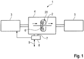
- the drive train 1 is constructed such that it has a hydrodynamic clutch 2, in particular a turbo clutch (VTK).
- a work machine 5 is driven via a primary drive machine 3 via an indicated transmission 4, the turbo clutch 2 being a part of this transmission 4 or an independent component in addition to such a transmission or instead of such a transmission 4.
- the work machine 5 can be, for example, a work machine 5 in the stationary area, in particular a belt conveyor, a shredder or the like.
- the turbo coupling 2 has a contactless thermal measuring device 6 indicated in the region of the turbo coupling 2.
- the non-contact thermal measuring device (BTM) 6 corresponds to a receiving device 7, which is in corresponding contact with an evaluation device (AWG) 8 or is part of one.
- a temperature signal sent by the contactless thermal measuring device 6 is correspondingly evaluated via the evaluation device 8, and in particular the primary drive machine 3, in particular an electric motor, can be activated. This is indicated by the arrows between the evaluation device 8 and the primary drive machine 3.
- the evaluation device 8 can receive signals from outside, for example a start signal or the like. This is indicated by the double arrow designated 9.
- the other direction in the double arrow 9 is intended to indicate that signals of the evaluation device 8 can be given outside, for example Warning signals regarding a exceeded temperature or the like.
- a fusible plug (SSS) 20 can also be seen in the area of the turbo coupling 2.
- SSS fusible plug
- the operating method according to the invention for the drive train 1 is now shown below using a selected example of a dynamic change in an operating state or load state.
- a dynamic change in an operating state or load state In this case, only the operating state changes, to the extent that there is a change from a switched-off operating state to an operating state of the start-up.
- any other dynamic change behaves analogously, so that this one example is sufficient for the person skilled in the art to understand the method according to the invention.
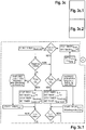
- FIG. 2 shows a simplified sequence for the drive train 1, in particular for the turbo coupling 2 of the drive train 1. Proceeding from an externally specified start signal, corresponding processing takes place, for example, in the area of the evaluation device 8, which has the logic steps implemented. After a short waiting time for initialization, the process sequence first checks whether a corresponding cooling time has been observed after a possible shutdown due to a predetermined maximum temperature being exceeded before proceeding further in the process sequence. After checking the function of the evaluation device 8, the electric motor 3 is then the primary one Drive unit 3 started. There is then a short waiting time for the start-up bypass before continuing with a check of the temperature signal of the measuring device 6 for plausibility.
- the minimum required start-up temperature difference is then checked for the first five seconds and then a case distinction is made as to whether it is a nominal operation or a start-up or a blockage.
- the temperature signal is corrected, which is not necessary in nominal operation.
- the temperature is then compared with a predetermined maximum temperature and the process sequence starts again with a check of the temperature signal for plausibility if the temperature value is below the predetermined maximum temperature. If this is not the case, the electric motor is switched off, that is to say the system is switched off in an emergency.
- the cooling time is checked again after the possible shutdown by exceeding the predetermined maximum temperature. This check of the cooling time and, if necessary, the delay in restarting ensures that an emergency shutdown occurs immediately again due to the unavoidable start-up temperature difference, since the current temperature value plus the required start-up temperature difference again exceeds the maximum temperature.
- the communication of the evaluation device 8 with the electric motor 3 as the primary drive machine is then typically very rudimentary because only a start release or an immediate shutdown of the electric motor 3 has to be communicated to the latter.
- step 3 steps 1 to 9 are shown again.
- the operation of the drive train 1 starts with a start command, whereupon the flag M hot is set to zero in step 1 after the power supply has been switched on.
- step 2 a time period of 10 seconds is waited before in step 3 it is checked whether the flag M is set hot to zero, that is to say the start process has only been initiated shortly beforehand or not. If this is not the case, step 3 is typically initiated via the area denoted by D in the manner which will be explained in more detail later, and there was previously a temperature-related shutdown of the electric motor 3.
- the switch-off timer is compared with the cooling timer, the switch-off timer being started with the temperature-related switch-off, and the cooling timer being specified as a value in the manner described in more detail later.
- Step 3 is then restarted and immediately runs through the first query due to the flag M hot being set to zero.
- step 4 the function of the evaluation device 8 is checked by querying a base current value of the non-contact thermal measuring device 6. If this is above a predefined threshold value, everything is OK, if not, a corresponding alarm is issued and an error message is generated.
- step 7 the plausibility of the temperature value is then checked by the measuring device 6 by querying whether the current supplied via the measuring device 6 is in a certain range. If this is the case, everything is OK, if this is not the case, a corresponding warning message is output and the electric motor 3 is stopped again. If the ambient temperature is too low, wait until the clutch or turbo clutch heats up.
- step 8 the minimum start-up temperature difference is then checked for the first five seconds, the electric motor 3 being stopped again in the event that the temperature reserve is too low for starting, and the flag M hot is set to 1. Then jump back to step 3. Otherwise it starts and Formula 1 calculates the temperature gradient.
- step 9 it is then evaluated whether the temperature gradient is correspondingly large or small, so that the cases differentiated with A and B in step 9 can be selected. These cases are the nominal operation (B) or the operation during start-up or a blockage (A), as shown in the illustration of the Figure 2 can be seen in the overview. In Figure 3b the sequence according to a is specified in more detail with steps 10, 11 and possibly 13.
- step 10 it is checked again whether the temperature gradient has a second limit value of 10 K / second. If this is the case, it is set to 10 K / second. If this is not the case, the timer t block is started immediately, which is otherwise started after the fixing.
- a time query as to whether the timer is below or above 5 seconds is then used to calculate the temperature of the turbo coupling according to either Formula 2 or Formula 3.
- a corresponding warning is then issued in the event of a blockage and, if necessary, measures are taken to remove the blockage.
- a remaining time is then calculated using Formula 4 and a warning is issued that, in the current conditions, the shutdown takes place in the amount calculated by the remaining time value.
- a check is then carried out to determine whether the temperature of the clutch has actually exceeded the maximum temperature limit ⁇ 3 . If this is not the case, point c is jumped back between points 6 and 7. If this is the case, the electric motor 3 is switched off in step 13 and the corresponding timers are shown in FIG Figure 3b set.
- step 3 After an alarm is output, the process jumps back to step 3, so that the electric motor 3 can be restarted after it has cooled sufficiently.
- monitoring for rated operation is described. This essentially involves temperature monitoring, which differentiates between a slightly elevated temperature with the need to reduce the load and a greatly increased temperature with the need to remove the load entirely. Only if no corresponding measure occurs, step 13 for stopping the electric motor 3 is analogous to the illustration in FIG Figure 3c otherwise the process is restarted between steps 6 and 7 and run continuously.
- the simulation described below is carried out, for example, depending on the load. This can be done for different load conditions and leads to different results.
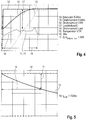
- An example is in the Figures 4 and 5 the The process is only shown as an example for the load of 100%.
- the engine speed 10 and the engine torque 11 and the secondary torque 12 of the turbo clutch 2 are shown.
- a curve 13 of the load speed and a curve 14 with the load torque can also be seen.
- the temperature curve in the turbo clutch 2, designated 15, is particularly decisive for the consideration shown here.
- the simulation shown includes other variables such as the ambient temperature of the turbo coupling and the starting temperature of the turbo coupling when switching off due to the maximum temperature ⁇ 3 being reached.
- the cooling behavior of the turbo clutch 2 can now be seen in a further simulation.
- the curve of the temperature of the turbo coupling 2 is again designated by reference number 15, the permissible operating temperature of the turbo coupling 2 at the specified load, here 100%, by reference number 18.
- the temperature curve 15 shows the simulated cooling of the turbo coupling 2 under the conditions described.
- the starting temperature difference is again via the arrow labeled 17 ⁇ start-up, min of 58K is displayed, which means that the cooling must have been at least around this 58 K compared to the permissible temperature 18 of the turbo coupling 2 in order not to provoke renewed overheating and switching off or load reduction on the turbo coupling 2 when starting.
- this value is entered in the diagram, then there is a corresponding value on the time axis for the corresponding point on the temperature profile 15, which is also shown by the arrow 19.
- This is the predetermined time value t cool which in the exemplary embodiment shown here is 7000 seconds. In the method according to the invention, the value t cool is therefore set to 7000 seconds in step 3 of the sequence.
Landscapes
- Engineering & Computer Science (AREA)
- Mechanical Engineering (AREA)
- General Engineering & Computer Science (AREA)
- Transportation (AREA)
- Automation & Control Theory (AREA)
- Chemical & Material Sciences (AREA)
- Combustion & Propulsion (AREA)
- Human Computer Interaction (AREA)
- Physics & Mathematics (AREA)
- Fluid Mechanics (AREA)
- Hydraulic Clutches, Magnetic Clutches, Fluid Clutches, And Fluid Joints (AREA)
- Supercharger (AREA)
- Control Of Turbines (AREA)
- Control Of Electric Motors In General (AREA)
Priority Applications (1)
| Application Number | Priority Date | Filing Date | Title |
|---|---|---|---|
| PL14755350T PL3049688T3 (pl) | 2013-09-24 | 2014-08-20 | Sposób obsługi cięgła napędowego ze sprzęgłem hydrodynamicznym |
Applications Claiming Priority (2)
| Application Number | Priority Date | Filing Date | Title |
|---|---|---|---|
| DE201310219180 DE102013219180A1 (de) | 2013-09-24 | 2013-09-24 | Verfahren zum Betreiben eines Antriebsstrangs mit einer hydrodynamischen Kupplung |
| PCT/EP2014/067748 WO2015043841A2 (de) | 2013-09-24 | 2014-08-20 | Verfahren zum betreiben eines antriebsstrangs mit einer hydrodynamischen kupplung |
Publications (2)
| Publication Number | Publication Date |
|---|---|
| EP3049688A2 EP3049688A2 (de) | 2016-08-03 |
| EP3049688B1 true EP3049688B1 (de) | 2020-06-03 |
Family
ID=51398608
Family Applications (1)
| Application Number | Title | Priority Date | Filing Date |
|---|---|---|---|
| EP14755350.7A Active EP3049688B1 (de) | 2013-09-24 | 2014-08-20 | Verfahren zum betreiben eines antriebsstrangs mit einer hydrodynamischen kupplung |
Country Status (6)
| Country | Link |
|---|---|
| US (1) | US10099696B2 (pl) |
| EP (1) | EP3049688B1 (pl) |
| CN (1) | CN105579729B (pl) |
| DE (1) | DE102013219180A1 (pl) |
| PL (1) | PL3049688T3 (pl) |
| WO (1) | WO2015043841A2 (pl) |
Families Citing this family (3)
| Publication number | Priority date | Publication date | Assignee | Title |
|---|---|---|---|---|
| WO2014167893A1 (ja) * | 2013-04-10 | 2014-10-16 | ジヤトコ株式会社 | 摩擦要素の温度警告装置及び温度警告方法 |
| DE102020201905B4 (de) | 2019-03-20 | 2025-01-02 | Ford Global Technologies, Llc | Zweimassenschwungrad-Baugruppe |
| CN110936938B (zh) * | 2019-12-18 | 2021-11-09 | 中车大连机车研究所有限公司 | 一种液力制动器驱动系统控制保护方法 |
Family Cites Families (12)
| Publication number | Priority date | Publication date | Assignee | Title |
|---|---|---|---|---|
| DE19614589A1 (de) * | 1996-04-12 | 1997-10-16 | Voith Turbo Kg | Hydrodynamische Kupplung |
| DE19937972A1 (de) * | 1999-08-11 | 2001-02-15 | Mannesmann Sachs Ag | Verfahren zum Ansteuern eines Antriebssystems und Antriebssystem |
| DE10316454B4 (de) * | 2002-04-10 | 2021-05-20 | Schaeffler Technologies AG & Co. KG | Vorrichtung und Verfahren zum Überwachen einer Kupplung |
| DE102004006730A1 (de) * | 2003-02-12 | 2004-08-26 | Luk Lamellen Und Kupplungsbau Beteiligungs Kg | Verfahren zum Durchführen von zumindest einer Schutzstrategie für die Kupplung eines automatisierten Schaltgetriebes eines Fahrzeuges |
| DE10361453B3 (de) * | 2003-12-23 | 2005-09-15 | Voith Turbo Gmbh & Co. Kg | Verschluss mit thermischer Sicherungsfunktion |
| DE102004006358B4 (de) * | 2004-02-09 | 2012-11-15 | Voith Turbo Gmbh & Co. Kg | Themperaturüberwachte hydrodynamische Maschine |
| DE102004023581A1 (de) * | 2004-05-13 | 2005-12-08 | Adam Opel Ag | Verfahren zur Steuerung einer Kupplung und/oder eines Kraftfahrzeuggetriebes |
| DE102005042363A1 (de) * | 2005-09-07 | 2007-03-15 | Zf Friedrichshafen Ag | Verfahren zur Schaltsteuerung eines Lastschaltgetriebes eines Kraftfahrzeugs |
| DE102006009608A1 (de) * | 2006-03-02 | 2007-09-06 | Zf Friedrichshafen Ag | Verfahren zur Steuerung bzw. Regelung einer drehmomentführenden Kupplung |
| KR100828674B1 (ko) * | 2006-08-02 | 2008-05-09 | 현대자동차주식회사 | 자동변속기 차량의 엔진 토크 제한장치 및 방법 |
| US7651441B2 (en) * | 2007-03-22 | 2010-01-26 | Gm Global Technology Operations, Inc. | Engine control for displacement on demand |
| DE102009037057A1 (de) * | 2009-08-13 | 2011-02-17 | Voith Patent Gmbh | Verfahren zum Steuern der Leistungsübertragung eines hydrodynamischen Retarders |
-
2013
- 2013-09-24 DE DE201310219180 patent/DE102013219180A1/de not_active Ceased
-
2014
- 2014-08-20 WO PCT/EP2014/067748 patent/WO2015043841A2/de not_active Ceased
- 2014-08-20 PL PL14755350T patent/PL3049688T3/pl unknown
- 2014-08-20 CN CN201480052765.8A patent/CN105579729B/zh active Active
- 2014-08-20 EP EP14755350.7A patent/EP3049688B1/de active Active
-
2016
- 2016-03-24 US US15/079,756 patent/US10099696B2/en active Active
Non-Patent Citations (1)
| Title |
|---|
| None * |
Also Published As
| Publication number | Publication date |
|---|---|
| US10099696B2 (en) | 2018-10-16 |
| DE102013219180A1 (de) | 2015-03-26 |
| WO2015043841A3 (de) | 2015-09-24 |
| CN105579729A (zh) | 2016-05-11 |
| EP3049688A2 (de) | 2016-08-03 |
| CN105579729B (zh) | 2017-09-26 |
| WO2015043841A2 (de) | 2015-04-02 |
| US20160264141A1 (en) | 2016-09-15 |
| PL3049688T3 (pl) | 2020-11-16 |
Similar Documents
| Publication | Publication Date | Title |
|---|---|---|
| EP3532356B1 (de) | Verfahren zum überwachen eines kraftfahrzeugs mit automatisierter fahrfunktion und vorrichtung zum durchführen des verfahrens | |
| EP2714483B1 (de) | Verfahren zum betrieb eines sicherheitssystems zur kollisionsvermeidung und/oder kollisionsschwereminderung in einem kraftfahrzeug und kraftfahrzeug | |
| EP3529892B1 (de) | Verfahren zum temperatur-derating von elektrischen maschinen | |
| DE19958934A1 (de) | Motorsteuereinheit | |
| WO2020127752A1 (de) | Verfahren zum überwachen einer batterie | |
| EP2337699B1 (de) | Verfahren zur verfügbarkeitserhöhung bei hybridfahrzeugen | |
| DE102022001489B3 (de) | Verfahren zum Betrieb eines elektrischen Antriebssystems für ein Kraftfahrzeug | |
| DE102009014469A1 (de) | Verfahren zur Steuerung einer Doppelkupplung | |
| DE102014216658B4 (de) | Verfahren zum Betrieb eines Kühlsystems einer Verbrennungskraftmaschine und Schutzsystem in einem Kühlsystem | |
| EP1447583B1 (de) | Verfahren zum Durchführen von zumindest einer Schutzstrategie für die Kupplung eines automatisierten Schaltgetriebes eines Fahrzeuges | |
| WO2011120496A1 (de) | Verfahren zum betreiben einer doppelkupplung | |
| DE102013219180A1 (de) | Verfahren zum Betreiben eines Antriebsstrangs mit einer hydrodynamischen Kupplung | |
| EP1645020B1 (de) | Vorrichtung und verfahren zum schutz einer elektrischen maschine | |
| EP3850748B1 (de) | Verfahren zum regeln der drehzahl oder des drehmoments eines motors, drehzahlregelungssystem und steuergerät | |
| DE102004043059A1 (de) | Verfahren und Schutzschaltung zur Temperaturüberwachung von kältemittelgekühlten Elektromotoren | |
| EP3614515B1 (de) | Sicherungseinrichtung, fahrzeug und verfahren | |
| DE102021003218A1 (de) | Vorrichtung und Verfahren zum Betrieb eines automatisiert betriebenen Fortbewegungsmittels | |
| DE102011006168B4 (de) | Verfahren zum Schutz einer Allradkupplung und Steuergerät mit einer Funktion zum Schutz einer Allradkupplung | |
| DE102014201567B4 (de) | Modellbasierte prädiktive Starterregelung eines Verbrennungsmotors | |
| EP1994620B1 (de) | Schutzeinrichtung und verfahren zum überwachen der gerätetemperatur eines gerätes | |
| EP3247599B1 (de) | Bremsvorrichtung mit retarder und verfahren zur regelung eines solchen | |
| EP1227377A2 (de) | Verfahren zum Schutz eines Stellantriebs vor Überlastung | |
| EP3418126A1 (de) | Verfahren zum betreiben eines bordnetzes | |
| DE10201598A1 (de) | Verfahren zum Schutz eines Stellantriebs vor Überlastung | |
| DE102012013104A1 (de) | Temperaturvorhersagevorrichtung und Überwachungsvorrichtung, sowie Verfahren zur Vorhersage einer Solltemperatur |
Legal Events
| Date | Code | Title | Description |
|---|---|---|---|
| PUAI | Public reference made under article 153(3) epc to a published international application that has entered the european phase |
Free format text: ORIGINAL CODE: 0009012 |
|
| 17P | Request for examination filed |
Effective date: 20160425 |
|
| AK | Designated contracting states |
Kind code of ref document: A2 Designated state(s): AL AT BE BG CH CY CZ DE DK EE ES FI FR GB GR HR HU IE IS IT LI LT LU LV MC MK MT NL NO PL PT RO RS SE SI SK SM TR |
|
| AX | Request for extension of the european patent |
Extension state: BA ME |
|
| DAX | Request for extension of the european patent (deleted) | ||
| STAA | Information on the status of an ep patent application or granted ep patent |
Free format text: STATUS: EXAMINATION IS IN PROGRESS |
|
| 17Q | First examination report despatched |
Effective date: 20190716 |
|
| RAP1 | Party data changed (applicant data changed or rights of an application transferred) |
Owner name: VOITH PATENT GMBH |
|
| GRAP | Despatch of communication of intention to grant a patent |
Free format text: ORIGINAL CODE: EPIDOSNIGR1 |
|
| STAA | Information on the status of an ep patent application or granted ep patent |
Free format text: STATUS: GRANT OF PATENT IS INTENDED |
|
| INTG | Intention to grant announced |
Effective date: 20200218 |
|
| GRAS | Grant fee paid |
Free format text: ORIGINAL CODE: EPIDOSNIGR3 |
|
| GRAA | (expected) grant |
Free format text: ORIGINAL CODE: 0009210 |
|
| STAA | Information on the status of an ep patent application or granted ep patent |
Free format text: STATUS: THE PATENT HAS BEEN GRANTED |
|
| AK | Designated contracting states |
Kind code of ref document: B1 Designated state(s): AL AT BE BG CH CY CZ DE DK EE ES FI FR GB GR HR HU IE IS IT LI LT LU LV MC MK MT NL NO PL PT RO RS SE SI SK SM TR |
|
| REG | Reference to a national code |
Ref country code: GB Ref legal event code: FG4D Free format text: NOT ENGLISH |
|
| REG | Reference to a national code |
Ref country code: CH Ref legal event code: EP Ref country code: AT Ref legal event code: REF Ref document number: 1277319 Country of ref document: AT Kind code of ref document: T Effective date: 20200615 |
|
| REG | Reference to a national code |
Ref country code: DE Ref legal event code: R096 Ref document number: 502014014260 Country of ref document: DE |
|
| REG | Reference to a national code |
Ref country code: LT Ref legal event code: MG4D |
|
| PG25 | Lapsed in a contracting state [announced via postgrant information from national office to epo] |
Ref country code: GR Free format text: LAPSE BECAUSE OF FAILURE TO SUBMIT A TRANSLATION OF THE DESCRIPTION OR TO PAY THE FEE WITHIN THE PRESCRIBED TIME-LIMIT Effective date: 20200904 Ref country code: LT Free format text: LAPSE BECAUSE OF FAILURE TO SUBMIT A TRANSLATION OF THE DESCRIPTION OR TO PAY THE FEE WITHIN THE PRESCRIBED TIME-LIMIT Effective date: 20200603 Ref country code: SE Free format text: LAPSE BECAUSE OF FAILURE TO SUBMIT A TRANSLATION OF THE DESCRIPTION OR TO PAY THE FEE WITHIN THE PRESCRIBED TIME-LIMIT Effective date: 20200603 Ref country code: NO Free format text: LAPSE BECAUSE OF FAILURE TO SUBMIT A TRANSLATION OF THE DESCRIPTION OR TO PAY THE FEE WITHIN THE PRESCRIBED TIME-LIMIT Effective date: 20200903 Ref country code: FI Free format text: LAPSE BECAUSE OF FAILURE TO SUBMIT A TRANSLATION OF THE DESCRIPTION OR TO PAY THE FEE WITHIN THE PRESCRIBED TIME-LIMIT Effective date: 20200603 |
|
| REG | Reference to a national code |
Ref country code: NL Ref legal event code: MP Effective date: 20200603 |
|
| PG25 | Lapsed in a contracting state [announced via postgrant information from national office to epo] |
Ref country code: BG Free format text: LAPSE BECAUSE OF FAILURE TO SUBMIT A TRANSLATION OF THE DESCRIPTION OR TO PAY THE FEE WITHIN THE PRESCRIBED TIME-LIMIT Effective date: 20200903 Ref country code: LV Free format text: LAPSE BECAUSE OF FAILURE TO SUBMIT A TRANSLATION OF THE DESCRIPTION OR TO PAY THE FEE WITHIN THE PRESCRIBED TIME-LIMIT Effective date: 20200603 Ref country code: HR Free format text: LAPSE BECAUSE OF FAILURE TO SUBMIT A TRANSLATION OF THE DESCRIPTION OR TO PAY THE FEE WITHIN THE PRESCRIBED TIME-LIMIT Effective date: 20200603 Ref country code: RS Free format text: LAPSE BECAUSE OF FAILURE TO SUBMIT A TRANSLATION OF THE DESCRIPTION OR TO PAY THE FEE WITHIN THE PRESCRIBED TIME-LIMIT Effective date: 20200603 |
|
| PG25 | Lapsed in a contracting state [announced via postgrant information from national office to epo] |
Ref country code: AL Free format text: LAPSE BECAUSE OF FAILURE TO SUBMIT A TRANSLATION OF THE DESCRIPTION OR TO PAY THE FEE WITHIN THE PRESCRIBED TIME-LIMIT Effective date: 20200603 Ref country code: NL Free format text: LAPSE BECAUSE OF FAILURE TO SUBMIT A TRANSLATION OF THE DESCRIPTION OR TO PAY THE FEE WITHIN THE PRESCRIBED TIME-LIMIT Effective date: 20200603 |
|
| PG25 | Lapsed in a contracting state [announced via postgrant information from national office to epo] |
Ref country code: EE Free format text: LAPSE BECAUSE OF FAILURE TO SUBMIT A TRANSLATION OF THE DESCRIPTION OR TO PAY THE FEE WITHIN THE PRESCRIBED TIME-LIMIT Effective date: 20200603 Ref country code: ES Free format text: LAPSE BECAUSE OF FAILURE TO SUBMIT A TRANSLATION OF THE DESCRIPTION OR TO PAY THE FEE WITHIN THE PRESCRIBED TIME-LIMIT Effective date: 20200603 Ref country code: RO Free format text: LAPSE BECAUSE OF FAILURE TO SUBMIT A TRANSLATION OF THE DESCRIPTION OR TO PAY THE FEE WITHIN THE PRESCRIBED TIME-LIMIT Effective date: 20200603 Ref country code: CZ Free format text: LAPSE BECAUSE OF FAILURE TO SUBMIT A TRANSLATION OF THE DESCRIPTION OR TO PAY THE FEE WITHIN THE PRESCRIBED TIME-LIMIT Effective date: 20200603 Ref country code: PT Free format text: LAPSE BECAUSE OF FAILURE TO SUBMIT A TRANSLATION OF THE DESCRIPTION OR TO PAY THE FEE WITHIN THE PRESCRIBED TIME-LIMIT Effective date: 20201006 Ref country code: SM Free format text: LAPSE BECAUSE OF FAILURE TO SUBMIT A TRANSLATION OF THE DESCRIPTION OR TO PAY THE FEE WITHIN THE PRESCRIBED TIME-LIMIT Effective date: 20200603 |
|
| PG25 | Lapsed in a contracting state [announced via postgrant information from national office to epo] |
Ref country code: SK Free format text: LAPSE BECAUSE OF FAILURE TO SUBMIT A TRANSLATION OF THE DESCRIPTION OR TO PAY THE FEE WITHIN THE PRESCRIBED TIME-LIMIT Effective date: 20200603 Ref country code: IS Free format text: LAPSE BECAUSE OF FAILURE TO SUBMIT A TRANSLATION OF THE DESCRIPTION OR TO PAY THE FEE WITHIN THE PRESCRIBED TIME-LIMIT Effective date: 20201003 |
|
| REG | Reference to a national code |
Ref country code: DE Ref legal event code: R097 Ref document number: 502014014260 Country of ref document: DE |
|
| PG25 | Lapsed in a contracting state [announced via postgrant information from national office to epo] |
Ref country code: MC Free format text: LAPSE BECAUSE OF FAILURE TO SUBMIT A TRANSLATION OF THE DESCRIPTION OR TO PAY THE FEE WITHIN THE PRESCRIBED TIME-LIMIT Effective date: 20200603 |
|
| PLBE | No opposition filed within time limit |
Free format text: ORIGINAL CODE: 0009261 |
|
| STAA | Information on the status of an ep patent application or granted ep patent |
Free format text: STATUS: NO OPPOSITION FILED WITHIN TIME LIMIT |
|
| PG25 | Lapsed in a contracting state [announced via postgrant information from national office to epo] |
Ref country code: DK Free format text: LAPSE BECAUSE OF FAILURE TO SUBMIT A TRANSLATION OF THE DESCRIPTION OR TO PAY THE FEE WITHIN THE PRESCRIBED TIME-LIMIT Effective date: 20200603 Ref country code: LU Free format text: LAPSE BECAUSE OF NON-PAYMENT OF DUE FEES Effective date: 20200820 |
|
| 26N | No opposition filed |
Effective date: 20210304 |
|
| REG | Reference to a national code |
Ref country code: BE Ref legal event code: MM Effective date: 20200831 |
|
| PG25 | Lapsed in a contracting state [announced via postgrant information from national office to epo] |
Ref country code: SI Free format text: LAPSE BECAUSE OF FAILURE TO SUBMIT A TRANSLATION OF THE DESCRIPTION OR TO PAY THE FEE WITHIN THE PRESCRIBED TIME-LIMIT Effective date: 20200603 |
|
| PG25 | Lapsed in a contracting state [announced via postgrant information from national office to epo] |
Ref country code: FR Free format text: LAPSE BECAUSE OF NON-PAYMENT OF DUE FEES Effective date: 20200831 |
|
| PG25 | Lapsed in a contracting state [announced via postgrant information from national office to epo] |
Ref country code: BE Free format text: LAPSE BECAUSE OF NON-PAYMENT OF DUE FEES Effective date: 20200831 Ref country code: IE Free format text: LAPSE BECAUSE OF NON-PAYMENT OF DUE FEES Effective date: 20200820 |
|
| REG | Reference to a national code |
Ref country code: AT Ref legal event code: MM01 Ref document number: 1277319 Country of ref document: AT Kind code of ref document: T Effective date: 20200820 |
|
| PG25 | Lapsed in a contracting state [announced via postgrant information from national office to epo] |
Ref country code: AT Free format text: LAPSE BECAUSE OF NON-PAYMENT OF DUE FEES Effective date: 20200820 |
|
| PG25 | Lapsed in a contracting state [announced via postgrant information from national office to epo] |
Ref country code: TR Free format text: LAPSE BECAUSE OF FAILURE TO SUBMIT A TRANSLATION OF THE DESCRIPTION OR TO PAY THE FEE WITHIN THE PRESCRIBED TIME-LIMIT Effective date: 20200603 Ref country code: MT Free format text: LAPSE BECAUSE OF FAILURE TO SUBMIT A TRANSLATION OF THE DESCRIPTION OR TO PAY THE FEE WITHIN THE PRESCRIBED TIME-LIMIT Effective date: 20200603 Ref country code: CY Free format text: LAPSE BECAUSE OF FAILURE TO SUBMIT A TRANSLATION OF THE DESCRIPTION OR TO PAY THE FEE WITHIN THE PRESCRIBED TIME-LIMIT Effective date: 20200603 |
|
| PG25 | Lapsed in a contracting state [announced via postgrant information from national office to epo] |
Ref country code: MK Free format text: LAPSE BECAUSE OF FAILURE TO SUBMIT A TRANSLATION OF THE DESCRIPTION OR TO PAY THE FEE WITHIN THE PRESCRIBED TIME-LIMIT Effective date: 20200603 |
|
| PGFP | Annual fee paid to national office [announced via postgrant information from national office to epo] |
Ref country code: DE Payment date: 20250820 Year of fee payment: 12 |
|
| PGFP | Annual fee paid to national office [announced via postgrant information from national office to epo] |
Ref country code: PL Payment date: 20250807 Year of fee payment: 12 Ref country code: IT Payment date: 20250825 Year of fee payment: 12 |
|
| PGFP | Annual fee paid to national office [announced via postgrant information from national office to epo] |
Ref country code: GB Payment date: 20250820 Year of fee payment: 12 |
|
| PGFP | Annual fee paid to national office [announced via postgrant information from national office to epo] |
Ref country code: CH Payment date: 20250901 Year of fee payment: 12 |