EP3048698A1 - Method for multi-fault power restoration of power distribution network - Google Patents
Method for multi-fault power restoration of power distribution network Download PDFInfo
- Publication number
- EP3048698A1 EP3048698A1 EP14866272.9A EP14866272A EP3048698A1 EP 3048698 A1 EP3048698 A1 EP 3048698A1 EP 14866272 A EP14866272 A EP 14866272A EP 3048698 A1 EP3048698 A1 EP 3048698A1
- Authority
- EP
- European Patent Office
- Prior art keywords
- restoration
- power
- fault
- independent
- areas
- Prior art date
- Legal status (The legal status is an assumption and is not a legal conclusion. Google has not performed a legal analysis and makes no representation as to the accuracy of the status listed.)
- Granted
Links
Images

Classifications
-
- H—ELECTRICITY
- H02—GENERATION; CONVERSION OR DISTRIBUTION OF ELECTRIC POWER
- H02H—EMERGENCY PROTECTIVE CIRCUIT ARRANGEMENTS
- H02H1/00—Details of emergency protective circuit arrangements
- H02H1/0092—Details of emergency protective circuit arrangements concerning the data processing means, e.g. expert systems, neural networks
-
- H—ELECTRICITY
- H02—GENERATION; CONVERSION OR DISTRIBUTION OF ELECTRIC POWER
- H02H—EMERGENCY PROTECTIVE CIRCUIT ARRANGEMENTS
- H02H7/00—Emergency protective circuit arrangements specially adapted for specific types of electric machines or apparatus or for sectionalised protection of cable or line systems, and effecting automatic switching in the event of an undesired change from normal working conditions
- H02H7/22—Emergency protective circuit arrangements specially adapted for specific types of electric machines or apparatus or for sectionalised protection of cable or line systems, and effecting automatic switching in the event of an undesired change from normal working conditions for distribution gear, e.g. bus-bar systems; for switching devices
-
- H—ELECTRICITY
- H02—GENERATION; CONVERSION OR DISTRIBUTION OF ELECTRIC POWER
- H02J—ELECTRIC POWER NETWORKS; CIRCUIT ARRANGEMENTS OR SYSTEMS FOR SUPPLYING OR DISTRIBUTING ELECTRIC POWER; SYSTEMS FOR STORING ELECTRIC ENERGY
- H02J3/00—Circuit arrangements for AC mains or AC distribution networks
- H02J3/007—Arrangements for selectively connecting one or more loads to one or more power sources or power lines
- H02J3/0073—Arrangements for selectively connecting one or more loads to one or more power sources or power lines by providing alternative feeding paths when the main path fails
-
- Y—GENERAL TAGGING OF NEW TECHNOLOGICAL DEVELOPMENTS; GENERAL TAGGING OF CROSS-SECTIONAL TECHNOLOGIES SPANNING OVER SEVERAL SECTIONS OF THE IPC; TECHNICAL SUBJECTS COVERED BY FORMER USPC CROSS-REFERENCE ART COLLECTIONS [XRACs] AND DIGESTS
- Y02—TECHNOLOGIES OR APPLICATIONS FOR MITIGATION OR ADAPTATION AGAINST CLIMATE CHANGE
- Y02E—REDUCTION OF GREENHOUSE GAS [GHG] EMISSIONS, RELATED TO ENERGY GENERATION, TRANSMISSION OR DISTRIBUTION
- Y02E40/00—Technologies for an efficient electrical power generation, transmission or distribution
- Y02E40/70—Smart grids as climate change mitigation technology in the energy generation sector
-
- Y—GENERAL TAGGING OF NEW TECHNOLOGICAL DEVELOPMENTS; GENERAL TAGGING OF CROSS-SECTIONAL TECHNOLOGIES SPANNING OVER SEVERAL SECTIONS OF THE IPC; TECHNICAL SUBJECTS COVERED BY FORMER USPC CROSS-REFERENCE ART COLLECTIONS [XRACs] AND DIGESTS
- Y04—INFORMATION OR COMMUNICATION TECHNOLOGIES HAVING AN IMPACT ON OTHER TECHNOLOGY AREAS
- Y04S—SYSTEMS INTEGRATING TECHNOLOGIES RELATED TO POWER NETWORK OPERATION, COMMUNICATION OR INFORMATION TECHNOLOGIES FOR IMPROVING THE ELECTRICAL POWER GENERATION, TRANSMISSION, DISTRIBUTION, MANAGEMENT OR USAGE, i.e. SMART GRIDS
- Y04S10/00—Systems supporting electrical power generation, transmission or distribution
- Y04S10/50—Systems or methods supporting the power network operation or management, involving a certain degree of interaction with the load-side end user applications
-
- Y—GENERAL TAGGING OF NEW TECHNOLOGICAL DEVELOPMENTS; GENERAL TAGGING OF CROSS-SECTIONAL TECHNOLOGIES SPANNING OVER SEVERAL SECTIONS OF THE IPC; TECHNICAL SUBJECTS COVERED BY FORMER USPC CROSS-REFERENCE ART COLLECTIONS [XRACs] AND DIGESTS
- Y04—INFORMATION OR COMMUNICATION TECHNOLOGIES HAVING AN IMPACT ON OTHER TECHNOLOGY AREAS
- Y04S—SYSTEMS INTEGRATING TECHNOLOGIES RELATED TO POWER NETWORK OPERATION, COMMUNICATION OR INFORMATION TECHNOLOGIES FOR IMPROVING THE ELECTRICAL POWER GENERATION, TRANSMISSION, DISTRIBUTION, MANAGEMENT OR USAGE, i.e. SMART GRIDS
- Y04S10/00—Systems supporting electrical power generation, transmission or distribution
- Y04S10/50—Systems or methods supporting the power network operation or management, involving a certain degree of interaction with the load-side end user applications
- Y04S10/52—Outage or fault management, e.g. fault detection or location
Definitions
- the present invention relates to the field of feeder automation, in particular to a power restoration method for a power distribution network with multi-faults.
- Fault restoration of a power distribution network plays an important role in ensuring the safety and the economical efficiency of a power grid, and is accordingly a problem focused by power systems all the time.
- the fault restoration of the power distribution network is a multi-target nonlinear constraint problem, and is mainly solved by an artificial intelligence algorithm and a heuristic search algorithm.
- an artificial intelligence algorithm and a heuristic search algorithm.
- the heuristic search algorithm has the advantages of high search speed, good real-time performance and the like. So in practical application, the heuristic search algorithm is most widely applied.
- the existing single-fault restoration strategy can not accomplish power restoration of non-fault power loss areas subjected to multi-faults.
- the power restoration of the fault restoration areas subjected to a single fault may influence each other under the following two conditions: under the first condition, the fault restoration areas subjected to a single fault are connected by a tie switch; under such a condition, in view of the physical structure, the power restoration line connected with one fault restoration area may provide spare capacity for another fault restoration area; however, when the fault restoration of the two fault restoration areas is solved by using a traditional method, the power restoration line connected with the one fault restoration area can not provide spare capacity for the another fault restoration area, so that the power restoration line can not be sufficiently utilized, and the final power restoration solution is not optimal.
- two fault restoration areas subjected to single-fault are connected by two tie switches; under such a condition, a common power restoration line exists between the two fault restoration areas; if power restoration of the two fault restoration areas is simultaneously performed by using a traditional single-fault restoration algorithm, the spare capacity of the common power restoration line may be reused, so that the power restoration solution can not meet the expected requirement and even can not be executed due to overload of the common power restoration line.
- the object of the present invention is to provide a power restoration method for a power distribution network subjected to multi-fault for solving the above problems, including: performing multi-fault judgment on multiple faults not completely processed, to form a plurality of multi-faults and a plurality of single-faults; then performing independent fault restoration area division on the multi-faults, and performing power restoration on the independent fault restoration areas one by one; and after the multiple faults are processed, performing power restoration on each single fault.
- a power restoration method for a power distribution network with multi-faults specifically comprises the following steps:
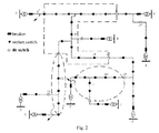
- a power line D fails within short time, power lines A and C have already failed, and a fault restoration strategy has not been completely executed; the fault restoration area of the power line D is restored by using an original single-fault restoration strategy; because a power line E needs to perform power restoration on the fault restoration area of the power line A, two fault restoration areas subjected to single-fault are connected by two tie switches; under such a condition, a common power restoration line is provided between the two fault restoration areas; if power restoration is simultaneously performed on the two fault restoration areas by using a traditional single-fault restoration algorithm, the spare capacity of the common power restoration line is reused, so that the fault restoration solution can not meet the expected requirement, e.g.
- a common power line E is provided between the two fault restoration areas, and when the power restoration is performed by using the single-fault restoration strategy, in the fault restoration solution of the fault restoration area A, the calculated load of the common power line E is the sum of the actual load of the common power line E before power restoration and the power loss load of the restored fault restoration area A restored by the common power line E; in the fault restoration solution of the fault restoration area C, the calculated load of the common power line E is the sum of the actual load of the common power line E before power restoration and the power loss load of the fault restoration area C restored by the common power line E; the actual load of the common power line E is the sum of the actual load of the common power line E before power restoration, the power loss load of the restored fault restoration area A and the power loss load of the restored fault restoration area C; and the spare capacity of the common power line E is reused, so that the final fault restoration solution can not meet the requirement, and even the fault restoration solution can not be executed due to overload of the common power line E.
- the original fault processing strategy not completely executed is stopped, and the outlet circuit breakers for the fault lines are turned on.
- the fault restoration areas of the power lines A and C form an independent fault restoration area 1
- the fault restoration area of the power line E forms an independent fault restoration area 2.
- the power lines B, F and H are independent power restoration lines for the independent fault restoration area 1
- the power line G is an independent power restoration line for the independent fault restoration area 2.
- the power line E is a common power restoration line for the two independent fault restoration areas.
- the method of step 5 that, three faults form a multi-fault, and the fault restoration area subjected to the multi-fault consists of two independent fault restoration areas. Power restoration is performed on the multi-fault according to the method of step 6, and the final fault restoration solution is as follows: turning on the tie switch 15, turning off section switches 12, 17, 24 and 34, and turning on tie switches 7, 19, 25 and 32.
- the power restoration line H originally supplying power to the fault restoration area of the power line A provides spare capacity for the fault restoration area of the power line C, so the result is optimized.
- Reuse of the common power restoration lines is avoided by performing power restoration on the independent fault restoration areas subjected to multi-fault one by one. If multiple faults are divided into a plurality of multi-faults, the power restoration may be simultaneously performed on the multi-fault restoration areas, thus contributing to the real-time performance of the fault restoration.
Landscapes
- Engineering & Computer Science (AREA)
- Power Engineering (AREA)
- Artificial Intelligence (AREA)
- Evolutionary Computation (AREA)
- Supply And Distribution Of Alternating Current (AREA)
- Remote Monitoring And Control Of Power-Distribution Networks (AREA)
Abstract
Description
- The present invention relates to the field of feeder automation, in particular to a power restoration method for a power distribution network with multi-faults.
- Fault restoration of a power distribution network plays an important role in ensuring the safety and the economical efficiency of a power grid, and is accordingly a problem focused by power systems all the time. The fault restoration of the power distribution network is a multi-target nonlinear constraint problem, and is mainly solved by an artificial intelligence algorithm and a heuristic search algorithm. Although a relative optimum restoration path may be found finally by the artificial intelligence algorithm, the calculation quantity is large, and the requirement for real-time performance is difficult to meet, while compared with the artificial intelligence algorithm, the heuristic search algorithm has the advantages of high search speed, good real-time performance and the like. So in practical application, the heuristic search algorithm is most widely applied. Although there have been many fault restoration methods for power distribution networks, these methods are only suitable for solving the single-fault problem, whereas multi-faults may appear in practical operation of a power grid under the following three conditions: (1) severe weather, e.g. rainstorm, snowstorm and typhoon; (2) destructive human-made disasters, e.g. substation fire caused by forest fire and the like; and (3) overload operation of most lines during power utilization peak in summer.
- When a power distribution network is in a condition with multiple faults, the existing single-fault restoration strategy can not accomplish power restoration of non-fault power loss areas subjected to multi-faults. After the power distribution network has multiple faults, the power restoration of the fault restoration areas subjected to a single fault may influence each other under the following two conditions: under the first condition, the fault restoration areas subjected to a single fault are connected by a tie switch; under such a condition, in view of the physical structure, the power restoration line connected with one fault restoration area may provide spare capacity for another fault restoration area; however, when the fault restoration of the two fault restoration areas is solved by using a traditional method, the power restoration line connected with the one fault restoration area can not provide spare capacity for the another fault restoration area, so that the power restoration line can not be sufficiently utilized, and the final power restoration solution is not optimal. Under the second condition, two fault restoration areas subjected to single-fault are connected by two tie switches; under such a condition, a common power restoration line exists between the two fault restoration areas; if power restoration of the two fault restoration areas is simultaneously performed by using a traditional single-fault restoration algorithm, the spare capacity of the common power restoration line may be reused, so that the power restoration solution can not meet the expected requirement and even can not be executed due to overload of the common power restoration line.
- The object of the present invention is to provide a power restoration method for a power distribution network subjected to multi-fault for solving the above problems, including: performing multi-fault judgment on multiple faults not completely processed, to form a plurality of multi-faults and a plurality of single-faults; then performing independent fault restoration area division on the multi-faults, and performing power restoration on the independent fault restoration areas one by one; and after the multiple faults are processed, performing power restoration on each single fault.
- To fulfill the above object, the present invention adopts the following technical solution:
- A multi-fault fault restoration method for a power distribution network, comprising the following plurality of steps:
- (1) stopping executing an original fault processing strategy not completely executed;
- (2) turning on outlet circuit breakers for fault lines;
- (3) re-dividing independent fault restoration areas: if some fault restoration areas subjected to a single fault are connected by a tie switch and these fault restoration areas subjected to a single fault are connected with the remaining fault restoration areas subjected to a single fault by at least one power restoration line, regarding these fault restoration areas subjected to a single fault as a whole, and calling them as independent fault restoration areas;
- (4) determining common power restoration lines and independent power restoration lines for the independent fault restoration areas;
- (5) re-determining multi-faults;
- (6) performing multi-fault power restoration;
- (7) forming a power restoration solution for the fault restoration areas subjected to single-fault by using a single-fault restoration method, wherein if the power distribution network has only one fault, this fault is a single-fault, the single-fault restoration algorithm is a traditional fault restoration algorithm when the power distribution network has only one fault.
- In step (3), the specific method for re-dividing independent fault restoration areas is as follows: after a new fault occurs, the downstream of the new fault line becomes a new fault restoration area; if there are independent fault restoration areas connected with the new fault restoration area by a tie switch, these independent fault restoration areas and the new fault restoration areas form new independent fault restoration areas.
- In step (4), the independent power restoration lines are defined as follows: if a certain power restoration line for multi-fault restoration areas can only supply power to an independent fault restoration area, the power line is an independent power restoration line for the independent fault restoration area; the common power restoration lines are defined as follows: if a certain power restoration line can supply power to a plurality of independent fault restoration area, the power line is a common power restoration line for these independent fault restoration area.
- Step (5) specifically includes the following steps:
- (5-1) randomly selecting one independent fault restoration area, finding all common power restoration lines for the independent fault restoration area, then finding independent fault restoration areas connected with the common power restoration lines, setting these independent fault restoration areas as a first layer of independent fault restoration areas, and randomly sequencing the independent fault restoration areas;
- (5-2) selecting each independent fault restoration area in the layer in sequence, and further finding the common power restoration lines connected with the first layer of independent fault restoration areas and independent fault restoration areas connected with the common power restoration lines to form a second layer of independent fault restoration areas; selecting each independent fault restoration area in the layer in sequence, and forming the second layer of independent fault restoration areas according to the method for forming the first layer of independent fault restoration areas;
- (5-3) proceeding by following the same principle, wherein after limited steps, faults involved in all the layers of independent fault restoration areas form multi-faults.
- Step (6) specifically includes the following steps:
- (6-1) calculating spare coefficients: calculating a spare coefficient for each independent fault restoration area in the absence of a common power restoration line according to the calculation formula

- (6-2) performing power restoration on the independent fault restoration areas one by one according to the spare coefficients from big to small.
Step (6-2) includes the following specific steps:- (a) performing power restoration on the independent fault restoration areas by using independent power restoration lines: when power restoration is performed on a certain independent fault restoration area, if the power supply to all the power loss loads is restored, the common power restoration line does not participate in the power restoration of the fault restoration areas any more; if the power supply to all the power loss loads can not be restored, a common power restoration line with the largest spare capacity is added for new power restoration; if the power supply to all the power loss loads still can not be restored, a common power restoration line is further added, till all the power loss loads are restored or no common power restoration line exists;
- (b) transforming the common power restoration lines: after the power restoration of a certain independent fault restoration area is completed, if some common power restoration lines connected with the certain independent fault restoration area only supply power to an independent fault restoration area, these common power restoration lines are transformed into corresponding independent power restoration lines for the independent fault restoration area; and if the load rate of the part of the common power restoration lines connected with the certain independent fault restoration area is greater than the spare coefficient of the to-be-restored independent fault restoration areas connected with these common power restoration lines, the part of the common power restoration lines do not participate in the power restoration of the to-be-restored independent fault restoration areas any more.
- (6-1) calculating spare coefficients: calculating a spare coefficient for each independent fault restoration area in the absence of a common power restoration line according to the calculation formula
- The present invention has the following advantages:
- 1. independent fault restoration area division is performed on the multi-faults, and power restoration is performed on the independent fault restoration areas one by one, so that reuse of the common power restoration lines is avoided;
- 2. the power restoration lines are sufficiently utilized, and the power restoration result is optimized;
- 3. power restoration can be performed on multiple fault restoration areas simultaneously, so that the power restoration efficiency is greatly improved, thus contributing to the real-time performance of power restoration.
-
-
Fig. 1 is a flow diagram of the present invention; -
Fig. 2 is a structure diagram of a power distribution network of the present invention; in which: A-I represent power lines; 12, 17, 24 and 34 represent section switches; and 7, 19, 25 and 32 represent tie switches. - The present invention will be further described below in combination with the accompanying drawings and the embodiments.
- As shown in
Fig. 1 , a power restoration method for a power distribution network with multi-faults specifically comprises the following steps: - (1) after the power distribution network has a new fault, stopping executing an original fault processing strategy not completely executed;
- (2) turning on outlet circuit breakers for all fault lines;
- (3) re-dividing independent fault restoration areas: after the new fault occurs, the downstream of the new fault line becomes a new fault restoration area; if there are independent fault restoration areas connected with the new fault restoration area by a tie switch, these independent fault restoration areas and the new fault restoration area form new independent fault restoration areas;
- (4) determining common power restoration lines and independent power restoration lines for the independent fault restoration areas: if a certain power restoration line for multi-fault restoration areas can only supply power to an independent fault restoration area, the power line is an independent power restoration line for the independent fault restoration area; if a certain power restoration line can supply power to multiple independent fault restoration areas, the power line is a common power restoration line for these independent fault restoration areas; after the new fault occurs, the common power restoration line and the independent power restoration line are changed, so the common power restoration line and the independent power restoration line for the independent fault restoration areas should be re-determined according to the above definition;
- (5) re-determining multi-faults: randomly selecting one independent fault restoration area, adding all common power restoration lines for supplying power to the independent fault restoration area and independent fault restoration areas connected with the common power restoration lines, setting the new independent fault restoration areas added at this stage as a first layer of independent fault restoration areas, and randomly sequencing the independent fault restoration areas; next, accessing each independent fault restoration area in the layer in sequence, and further adding the common power restoration lines connected with the first layer of independent fault restoration areas and independent fault restoration areas connected with the common power restoration lines to form a second layer of independent fault restoration areas; proceeding by following the same principle, and completing the search after limited steps, wherein faults involved in all the found independent fault restoration areas form multi-faults;
- (6) performing power restoration on the independent fault restoration areas subjected to multi-faults one by one according to the ratio of the spare capacity of the independent power restoration lines for the independent fault restoration areas to the power loss loads of the independent fault restoration areas: first, calculating a spare coefficient for each independent fault restoration area in the absence of a common power restoration line according to the calculation formula

- (7) forming a power restoration solution for the fault restoration areas subjected to single-fault by using a single-fault restoration method.
- As shown in
Fig. 2 , it is supposed that before a power line D fails within short time, power lines A and C have already failed, and a fault restoration strategy has not been completely executed; the fault restoration area of the power line D is restored by using an original single-fault restoration strategy; because a power line E needs to perform power restoration on the fault restoration area of the power line A, two fault restoration areas subjected to single-fault are connected by two tie switches; under such a condition, a common power restoration line is provided between the two fault restoration areas; if power restoration is simultaneously performed on the two fault restoration areas by using a traditional single-fault restoration algorithm, the spare capacity of the common power restoration line is reused, so that the fault restoration solution can not meet the expected requirement, e.g. there are two fault restoration areas A and C in the figure, a common power line E is provided between the two fault restoration areas, and when the power restoration is performed by using the single-fault restoration strategy, in the fault restoration solution of the fault restoration area A, the calculated load of the common power line E is the sum of the actual load of the common power line E before power restoration and the power loss load of the restored fault restoration area A restored by the common power line E; in the fault restoration solution of the fault restoration area C, the calculated load of the common power line E is the sum of the actual load of the common power line E before power restoration and the power loss load of the fault restoration area C restored by the common power line E; the actual load of the common power line E is the sum of the actual load of the common power line E before power restoration, the power loss load of the restored fault restoration area A and the power loss load of the restored fault restoration area C; and the spare capacity of the common power line E is reused, so that the final fault restoration solution can not meet the requirement, and even the fault restoration solution can not be executed due to overload of the common power line E. - However, such problems can be solved by using the method proposed by the present application.
- First, the original fault processing strategy not completely executed is stopped, and the outlet circuit breakers for the fault lines are turned on. It could be known according to the method of step 3 that, the fault restoration areas of the power lines A and C form an independent fault restoration area 1, and the fault restoration area of the power line E forms an independent fault restoration area 2. It could be known according to the method of step 4 that, the power lines B, F and H are independent power restoration lines for the independent fault restoration area 1, and the power line G is an independent power restoration line for the independent fault restoration area 2. The power line E is a common power restoration line for the two independent fault restoration areas. It could be known according to the method of step 5 that, three faults form a multi-fault, and the fault restoration area subjected to the multi-fault consists of two independent fault restoration areas. Power restoration is performed on the multi-fault according to the method of step 6, and the final fault restoration solution is as follows: turning on the tie switch 15, turning off section switches 12, 17, 24 and 34, and turning on tie switches 7, 19, 25 and 32.
- It could be seen from the final fault restoration solution that the power restoration line H originally supplying power to the fault restoration area of the power line A provides spare capacity for the fault restoration area of the power line C, so the result is optimized. Reuse of the common power restoration lines is avoided by performing power restoration on the independent fault restoration areas subjected to multi-fault one by one. If multiple faults are divided into a plurality of multi-faults, the power restoration may be simultaneously performed on the multi-fault restoration areas, thus contributing to the real-time performance of the fault restoration.
- Although the specific implementations of the present invention are described above in combination with the accompanying drawings, the protection scope of the present invention is not limited thereto. It should be understood by those skilled in the art that various modifications or variations may be made on the basis of the technical solutions of the present invention without any creative effort, and these modifications or variations are still within the protection scope of the present invention.
Claims (6)
- A power restoration method for a power distribution network with multi-faults, comprising the following steps:(1) stopping executing an original fault processing strategy not completely executed;(2) turning on outlet circuit breakers for fault lines;(3) re-dividing independent fault restoration areas: if some fault restoration areas subjected to a single fault are connected by a tie switch and these fault restoration areas subjected to a single fault are connected with the remaining fault restoration areas subjected to a single fault by at least one power restoration line, regarding these fault restoration areas subjected to a single fault as a whole, and calling them as independent fault restoration areas;(4) determining common power restoration lines and independent power restoration lines for the independent fault restoration areas;(5) re-determining multi-faults;(6) performing multi-fault power restoration;(7) forming a power restoration solution for the fault restoration areas subjected to single-fault by using a single-fault restoration method, wherein if the power distribution network has only one fault, this fault is a single-fault, the single-fault restoration algorithm is a traditional fault restoration algorithm when the power distribution network has only one fault.
- The power restoration method for the power distribution network with multi-faults of claim 1, wherein in step (3), the specific method for re-dividing independent fault restoration areas is as follows: after a new fault occurs, the downstream of the new fault line becomes a new fault restoration area; if there are independent fault restoration areas connected with the new fault restoration area by a tie switch, these independent fault restoration areas and the new fault restoration area form new independent fault restoration areas.
- The power restoration method for the power distribution network with multi-faults of claim 1, wherein in step (4), the independent power restoration lines are defined as follows: if a certain power restoration line for fault restoration areas subjected to multi-faults can only supply power to an independent fault restoration area, the power line is an independent power restoration line for the independent fault restoration area; the common power restoration lines are defined as follows: if a certain power restoration line can supply power to a plurality of independent fault restoration areas, the power line is a common power restoration line for these independent fault restoration areas.
- The power restoration method for the power distribution network with multi-faults of claim 1, wherein step (5) specifically comprises the following steps:(5-1) randomly selecting one independent fault restoration area, finding all common power restoration lines for the independent fault restoration area, then finding independent fault restoration areas connected with the common power restoration lines, setting these independent fault restoration areas as a first layer of independent fault restoration areas, and randomly sequencing the independent fault restoration areas;(5-2) selecting each independent fault restoration area on the layer in sequence, and further finding the common power restoration lines connected with the first layer of independent fault restoration areas and independent fault restoration areas connected with the common power restoration lines to form a second layer of independent fault restoration areas; selecting each independent fault restoration area on the layer in sequence, and forming the second layer of independent fault restoration areas according to the method for forming the first layer of independent fault restoration areas;(5-3) proceeding by following the same principle, wherein after limited steps, faults involved in the independent fault restoration areas of all the layers form multi-faults.
- The power restoration method for the power distribution network with multi-faults of claim 1, wherein step (6) specifically comprises the following steps:(6-1) calculating spare coefficients: calculating a spare coefficient for each independent fault restoration area in the absence of a common power restoration line according to a formula
 (6-2) performing power restoration on the independent fault restoration areas one by one according to the spare coefficients from big to small.
 - The power restoration method for the power distribution network with multi-faults of claim 5, wherein step (6-2) comprises the following specific steps:(a) performing power restoration on the independent fault restoration areas by using independent power restoration lines: when power restoration is performed on a certain independent fault restoration area, if the power supply to all the power loss loads is restored, the common power restoration line does not participate in the power restoration of the fault restoration areas any more; if the power supply to all the power loss loads can not be restored, a common power restoration line with the largest spare capacity is added for new power restoration; if the power supply to all the power loss loads still can not be restored, a common power restoration line is further added, till all the power loss loads are restored or no common power restoration line exists;(b) transforming the common power restoration lines: after the power restoration of a certain independent fault restoration area is completed, if some common power restoration lines connected with the certain independent fault restoration area only supply power to an independent fault restoration area, these common power restoration lines are transformed into corresponding independent power restoration lines for the independent fault restoration area; and if the load rate of the part of the common power restoration lines connected with the certain independent fault restoration area is greater than the spare coefficient of the to-be-restored independent fault restoration areas connected with these common power restoration lines, the part of the common power restoration lines do not participate in the power restoration of the to-be-restored independent fault restoration areas any more.
Applications Claiming Priority (2)
| Application Number | Priority Date | Filing Date | Title |
|---|---|---|---|
| CN201310625280.0A CN103593708B (en) | 2013-11-28 | 2013-11-28 | A kind of method for multi-failure power restoration of power distribution network |
| PCT/CN2014/080290 WO2015078172A1 (en) | 2013-11-28 | 2014-06-19 | Method for multi-fault power restoration of power distribution network |
Publications (3)
| Publication Number | Publication Date |
|---|---|
| EP3048698A1 true EP3048698A1 (en) | 2016-07-27 |
| EP3048698A4 EP3048698A4 (en) | 2016-12-07 |
| EP3048698B1 EP3048698B1 (en) | 2020-01-08 |
Family
ID=50083838
Family Applications (1)
| Application Number | Title | Priority Date | Filing Date |
|---|---|---|---|
| EP14866272.9A Active EP3048698B1 (en) | 2013-11-28 | 2014-06-19 | Method for multi-fault power restoration of power distribution network |
Country Status (4)
| Country | Link |
|---|---|
| US (1) | US9882370B2 (en) |
| EP (1) | EP3048698B1 (en) |
| CN (1) | CN103593708B (en) |
| WO (1) | WO2015078172A1 (en) |
Cited By (1)
| Publication number | Priority date | Publication date | Assignee | Title |
|---|---|---|---|---|
| CN110245858A (en) * | 2019-06-11 | 2019-09-17 | 上海电力学院 | A kind of micro-capacitance sensor reliability estimation method containing electric automobile charging station |
Families Citing this family (16)
| Publication number | Priority date | Publication date | Assignee | Title |
|---|---|---|---|---|
| CN103593708B (en) | 2013-11-28 | 2017-01-04 | 国家电网公司 | A kind of method for multi-failure power restoration of power distribution network |
| US10361907B2 (en) * | 2015-04-27 | 2019-07-23 | Northeastern University | System for networking and analyzing geospatial data, human infrastructure, and natural elements |
| CN107730093B (en) * | 2017-09-27 | 2021-07-13 | 广东电网有限责任公司佛山供电局 | System and method for power grid accident re-routing path |
| CN109472384A (en) * | 2018-04-09 | 2019-03-15 | 国网浙江省电力有限公司嘉兴供电公司 | An optimization method of power distribution equipment maintenance strategy based on big data |
| CN108777482A (en) * | 2018-05-28 | 2018-11-09 | 国家电网公司华中分部 | A kind of optimal power transmission path decision method of the power grid of rule-based formula |
| CN108921410B (en) * | 2018-06-22 | 2023-02-14 | 天津大学 | Method for constructing and improving elastic resilience index of power distribution network |
| CN109657912B (en) * | 2018-11-15 | 2022-01-25 | 国网浙江省电力有限公司金华供电公司 | Visual power grid risk management and control method and system |
| CN110350510B (en) * | 2019-05-23 | 2023-04-28 | 国网河南省电力公司郑州供电公司 | Power distribution network power supply recovery method considering fault influence degree |
| CN111130898B (en) * | 2019-12-30 | 2020-12-01 | 广东电网有限责任公司 | Fault recovery method of power communication network based on service characteristics and node reliability |
| CN111564846A (en) * | 2020-05-21 | 2020-08-21 | 国网江西省电力有限公司电力科学研究院 | A power flow optimization control method for green scheduling |
| CN111736034A (en) * | 2020-05-23 | 2020-10-02 | 张涛涛 | Rapid identification method of distribution network fault area based on power outage distribution transformer and topology analysis |
| CN112701688A (en) * | 2021-01-28 | 2021-04-23 | 国网河北省电力有限公司电力科学研究院 | Power distribution network fault recovery method considering emergency electric vehicle and terminal equipment |
| CN112865087B (en) * | 2021-01-28 | 2023-08-08 | 国网河北省电力有限公司电力科学研究院 | Power distribution network fault recovery method and terminal equipment |
| CN114056168B (en) * | 2021-10-28 | 2024-04-12 | 广东电网有限责任公司广州供电局 | Charging station power supply method, control device, computer equipment and storage medium |
| CN114243799B (en) * | 2022-01-05 | 2023-11-07 | 国网浙江省电力有限公司宁波供电公司 | Deep reinforcement learning power distribution network fault recovery method based on distributed power supply |
| CN120566426B (en) * | 2025-06-12 | 2025-12-09 | 广东电网有限责任公司广州供电局 | Power grid fault recovery method and system based on real-time monitoring |
Family Cites Families (7)
| Publication number | Priority date | Publication date | Assignee | Title |
|---|---|---|---|---|
| US5928368A (en) * | 1994-06-23 | 1999-07-27 | Tandem Computers Incorporated | Method and apparatus for fault-tolerant multiprocessing system recovery from power failure or drop-outs |
| US9917436B2 (en) * | 2007-10-30 | 2018-03-13 | General Electric Company | System and method for control of power distribution |
| US9171250B2 (en) * | 2009-12-04 | 2015-10-27 | Abb Research Ltd. | Restoration switching analysis with modified genetic algorithm |
| CN102509153B (en) | 2011-11-03 | 2014-12-31 | 中国电力科学研究院 | Method for reconstructing distribution network after fault |
| US9250674B2 (en) * | 2013-01-18 | 2016-02-02 | General Electric Company | Methods and systems for restoring power based on forecasted loads |
| CN103259261B (en) | 2013-04-22 | 2015-03-11 | 湖南大学 | Load distribution method for multi-line power restoration after power distribution network fault |
| CN103593708B (en) | 2013-11-28 | 2017-01-04 | 国家电网公司 | A kind of method for multi-failure power restoration of power distribution network |
-
2013
- 2013-11-28 CN CN201310625280.0A patent/CN103593708B/en active Active
-
2014
- 2014-06-19 US US14/784,788 patent/US9882370B2/en active Active
- 2014-06-19 EP EP14866272.9A patent/EP3048698B1/en active Active
- 2014-06-19 WO PCT/CN2014/080290 patent/WO2015078172A1/en not_active Ceased
Cited By (2)
| Publication number | Priority date | Publication date | Assignee | Title |
|---|---|---|---|---|
| CN110245858A (en) * | 2019-06-11 | 2019-09-17 | 上海电力学院 | A kind of micro-capacitance sensor reliability estimation method containing electric automobile charging station |
| CN110245858B (en) * | 2019-06-11 | 2022-06-10 | 上海电力学院 | A reliability assessment method for microgrid including electric vehicle charging station |
Also Published As
| Publication number | Publication date |
|---|---|
| CN103593708B (en) | 2017-01-04 |
| US20160190789A1 (en) | 2016-06-30 |
| EP3048698A4 (en) | 2016-12-07 |
| US9882370B2 (en) | 2018-01-30 |
| CN103593708A (en) | 2014-02-19 |
| EP3048698B1 (en) | 2020-01-08 |
| WO2015078172A1 (en) | 2015-06-04 |
Similar Documents
| Publication | Publication Date | Title |
|---|---|---|
| EP3048698B1 (en) | Method for multi-fault power restoration of power distribution network | |
| CN103279807B (en) | A kind of static risk assessment method for power grid in severe weather | |
| CN102222890B (en) | A cascading failure analysis method for complex power grids considering severe weather factors | |
| Papadopoulos et al. | Simulation and analysis of small and medium size power systems containing wind turbines | |
| CN116071042B (en) | A distribution network fault recovery method and device considering the impact of waterlogging disasters | |
| CN102751723A (en) | Ship alternative-current zone power distribution network system and reliability analysis method thereof | |
| CN103558481B (en) | Many times DC line couplings of parallel erected on same tower cause the method for discrimination of commutation failure | |
| CN105337268A (en) | Power distribution network wide-area protection method comprising distributed power supply | |
| CN108521122A (en) | A Static Security Analysis Method of Power System Considering Standby and Automatic Switching | |
| CN105207276B (en) | Multi-infeed power transmission system fault partition current limiter installation method based on graph theory | |
| Hadjikypris et al. | Transient fault studies in a multi-terminal VSC-HVDC grid utilizing protection means through DC circuit breakers | |
| CN107067126B (en) | A thermally stable key transmission channel identification method based on power flow transfer ratio | |
| CN111262227A (en) | Method and device for regulating system topology to limit breaker on-off short-circuit current | |
| CN107959284A (en) | A kind of power flow transfer recognizer based on multiple branch circuit excision and away from path | |
| CN107124006B (en) | Adaptive emergency control method for equipment overload based on automatic identification of measure sensitivity | |
| CN104466970A (en) | Spare power automatic switching dynamic intertripping control method, device and system | |
| CN105939021A (en) | Power grid frequency control method of considering low voltage ride-through capability of fan | |
| CN104201767A (en) | Optimized switching-on/off control method for busbar automatic transfer switch pressure plate | |
| CN206117592U (en) | Manifold device of cancellation direct current fuse | |
| CN104483597A (en) | Failure interval positioning method applied to power distribution network with distributed power supplies | |
| CN103457250A (en) | Power distribution network power supply recovery method based on root tree cutting | |
| CN109245063A (en) | Power distribution network relay protection scheme scheme performance comparative approach | |
| CN103532114B (en) | A kind of new method for carrying out overcurrent protection to cascade radiation type distribution line | |
| CN103593709B (en) | A kind of multiple failure service restoration method based on load balancing | |
| CN112180205B (en) | Intelligent distributed single-phase grounding line selection method and system for power distribution network |
Legal Events
| Date | Code | Title | Description |
|---|---|---|---|
| PUAI | Public reference made under article 153(3) epc to a published international application that has entered the european phase |
Free format text: ORIGINAL CODE: 0009012 |
|
| 17P | Request for examination filed |
Effective date: 20160421 |
|
| AK | Designated contracting states |
Kind code of ref document: A1 Designated state(s): AL AT BE BG CH CY CZ DE DK EE ES FI FR GB GR HR HU IE IS IT LI LT LU LV MC MK MT NL NO PL PT RO RS SE SI SK SM TR |
|
| AX | Request for extension of the european patent |
Extension state: BA ME |
|
| RIN1 | Information on inventor provided before grant (corrected) |
Inventor name: LI, SHANGZHEN Inventor name: LIANG, YUANBIN Inventor name: LIU, XUJIE Inventor name: WU, GUANBIN Inventor name: LI, HONGMEI Inventor name: ZHU, GUOFANG Inventor name: LI, SUN Inventor name: LI, YONG Inventor name: NIU, JINCANG Inventor name: XU, NAIYUAN Inventor name: ZHAO, BAOGUANG Inventor name: SHI, XIN |
|
| A4 | Supplementary search report drawn up and despatched |
Effective date: 20161109 |
|
| RIC1 | Information provided on ipc code assigned before grant |
Ipc: H02J 3/00 20060101ALI20161103BHEP Ipc: H02H 1/00 20060101ALI20161103BHEP Ipc: H02J 13/00 20060101AFI20161103BHEP Ipc: H02H 7/22 20060101ALI20161103BHEP |
|
| DAX | Request for extension of the european patent (deleted) | ||
| STAA | Information on the status of an ep patent application or granted ep patent |
Free format text: STATUS: REQUEST FOR EXAMINATION WAS MADE |
|
| STAA | Information on the status of an ep patent application or granted ep patent |
Free format text: STATUS: EXAMINATION IS IN PROGRESS |
|
| 17Q | First examination report despatched |
Effective date: 20190411 |
|
| GRAP | Despatch of communication of intention to grant a patent |
Free format text: ORIGINAL CODE: EPIDOSNIGR1 |
|
| STAA | Information on the status of an ep patent application or granted ep patent |
Free format text: STATUS: GRANT OF PATENT IS INTENDED |
|
| INTG | Intention to grant announced |
Effective date: 20190911 |
|
| GRAS | Grant fee paid |
Free format text: ORIGINAL CODE: EPIDOSNIGR3 |
|
| GRAA | (expected) grant |
Free format text: ORIGINAL CODE: 0009210 |
|
| STAA | Information on the status of an ep patent application or granted ep patent |
Free format text: STATUS: THE PATENT HAS BEEN GRANTED |
|
| AK | Designated contracting states |
Kind code of ref document: B1 Designated state(s): AL AT BE BG CH CY CZ DE DK EE ES FI FR GB GR HR HU IE IS IT LI LT LU LV MC MK MT NL NO PL PT RO RS SE SI SK SM TR |
|
| REG | Reference to a national code |
Ref country code: GB Ref legal event code: FG4D |
|
| REG | Reference to a national code |
Ref country code: CH Ref legal event code: EP |
|
| REG | Reference to a national code |
Ref country code: IE Ref legal event code: FG4D |
|
| REG | Reference to a national code |
Ref country code: DE Ref legal event code: R096 Ref document number: 602014059885 Country of ref document: DE |
|
| REG | Reference to a national code |
Ref country code: AT Ref legal event code: REF Ref document number: 1223875 Country of ref document: AT Kind code of ref document: T Effective date: 20200215 |
|
| REG | Reference to a national code |
Ref country code: NL Ref legal event code: MP Effective date: 20200108 |
|
| REG | Reference to a national code |
Ref country code: LT Ref legal event code: MG4D |
|
| PG25 | Lapsed in a contracting state [announced via postgrant information from national office to epo] |
Ref country code: PT Free format text: LAPSE BECAUSE OF FAILURE TO SUBMIT A TRANSLATION OF THE DESCRIPTION OR TO PAY THE FEE WITHIN THE PRESCRIBED TIME-LIMIT Effective date: 20200531 Ref country code: NL Free format text: LAPSE BECAUSE OF FAILURE TO SUBMIT A TRANSLATION OF THE DESCRIPTION OR TO PAY THE FEE WITHIN THE PRESCRIBED TIME-LIMIT Effective date: 20200108 Ref country code: RS Free format text: LAPSE BECAUSE OF FAILURE TO SUBMIT A TRANSLATION OF THE DESCRIPTION OR TO PAY THE FEE WITHIN THE PRESCRIBED TIME-LIMIT Effective date: 20200108 Ref country code: NO Free format text: LAPSE BECAUSE OF FAILURE TO SUBMIT A TRANSLATION OF THE DESCRIPTION OR TO PAY THE FEE WITHIN THE PRESCRIBED TIME-LIMIT Effective date: 20200408 Ref country code: LT Free format text: LAPSE BECAUSE OF FAILURE TO SUBMIT A TRANSLATION OF THE DESCRIPTION OR TO PAY THE FEE WITHIN THE PRESCRIBED TIME-LIMIT Effective date: 20200108 Ref country code: FI Free format text: LAPSE BECAUSE OF FAILURE TO SUBMIT A TRANSLATION OF THE DESCRIPTION OR TO PAY THE FEE WITHIN THE PRESCRIBED TIME-LIMIT Effective date: 20200108 |
|
| PG25 | Lapsed in a contracting state [announced via postgrant information from national office to epo] |
Ref country code: BG Free format text: LAPSE BECAUSE OF FAILURE TO SUBMIT A TRANSLATION OF THE DESCRIPTION OR TO PAY THE FEE WITHIN THE PRESCRIBED TIME-LIMIT Effective date: 20200408 Ref country code: SE Free format text: LAPSE BECAUSE OF FAILURE TO SUBMIT A TRANSLATION OF THE DESCRIPTION OR TO PAY THE FEE WITHIN THE PRESCRIBED TIME-LIMIT Effective date: 20200108 Ref country code: LV Free format text: LAPSE BECAUSE OF FAILURE TO SUBMIT A TRANSLATION OF THE DESCRIPTION OR TO PAY THE FEE WITHIN THE PRESCRIBED TIME-LIMIT Effective date: 20200108 Ref country code: IS Free format text: LAPSE BECAUSE OF FAILURE TO SUBMIT A TRANSLATION OF THE DESCRIPTION OR TO PAY THE FEE WITHIN THE PRESCRIBED TIME-LIMIT Effective date: 20200508 Ref country code: HR Free format text: LAPSE BECAUSE OF FAILURE TO SUBMIT A TRANSLATION OF THE DESCRIPTION OR TO PAY THE FEE WITHIN THE PRESCRIBED TIME-LIMIT Effective date: 20200108 Ref country code: GR Free format text: LAPSE BECAUSE OF FAILURE TO SUBMIT A TRANSLATION OF THE DESCRIPTION OR TO PAY THE FEE WITHIN THE PRESCRIBED TIME-LIMIT Effective date: 20200409 |
|
| REG | Reference to a national code |
Ref country code: DE Ref legal event code: R097 Ref document number: 602014059885 Country of ref document: DE |
|
| PG25 | Lapsed in a contracting state [announced via postgrant information from national office to epo] |
Ref country code: EE Free format text: LAPSE BECAUSE OF FAILURE TO SUBMIT A TRANSLATION OF THE DESCRIPTION OR TO PAY THE FEE WITHIN THE PRESCRIBED TIME-LIMIT Effective date: 20200108 Ref country code: SM Free format text: LAPSE BECAUSE OF FAILURE TO SUBMIT A TRANSLATION OF THE DESCRIPTION OR TO PAY THE FEE WITHIN THE PRESCRIBED TIME-LIMIT Effective date: 20200108 Ref country code: SK Free format text: LAPSE BECAUSE OF FAILURE TO SUBMIT A TRANSLATION OF THE DESCRIPTION OR TO PAY THE FEE WITHIN THE PRESCRIBED TIME-LIMIT Effective date: 20200108 Ref country code: DK Free format text: LAPSE BECAUSE OF FAILURE TO SUBMIT A TRANSLATION OF THE DESCRIPTION OR TO PAY THE FEE WITHIN THE PRESCRIBED TIME-LIMIT Effective date: 20200108 Ref country code: RO Free format text: LAPSE BECAUSE OF FAILURE TO SUBMIT A TRANSLATION OF THE DESCRIPTION OR TO PAY THE FEE WITHIN THE PRESCRIBED TIME-LIMIT Effective date: 20200108 Ref country code: CZ Free format text: LAPSE BECAUSE OF FAILURE TO SUBMIT A TRANSLATION OF THE DESCRIPTION OR TO PAY THE FEE WITHIN THE PRESCRIBED TIME-LIMIT Effective date: 20200108 Ref country code: ES Free format text: LAPSE BECAUSE OF FAILURE TO SUBMIT A TRANSLATION OF THE DESCRIPTION OR TO PAY THE FEE WITHIN THE PRESCRIBED TIME-LIMIT Effective date: 20200108 |
|
| PLBE | No opposition filed within time limit |
Free format text: ORIGINAL CODE: 0009261 |
|
| STAA | Information on the status of an ep patent application or granted ep patent |
Free format text: STATUS: NO OPPOSITION FILED WITHIN TIME LIMIT |
|
| REG | Reference to a national code |
Ref country code: AT Ref legal event code: MK05 Ref document number: 1223875 Country of ref document: AT Kind code of ref document: T Effective date: 20200108 |
|
| 26N | No opposition filed |
Effective date: 20201009 |
|
| PG25 | Lapsed in a contracting state [announced via postgrant information from national office to epo] |
Ref country code: MC Free format text: LAPSE BECAUSE OF FAILURE TO SUBMIT A TRANSLATION OF THE DESCRIPTION OR TO PAY THE FEE WITHIN THE PRESCRIBED TIME-LIMIT Effective date: 20200108 Ref country code: AT Free format text: LAPSE BECAUSE OF FAILURE TO SUBMIT A TRANSLATION OF THE DESCRIPTION OR TO PAY THE FEE WITHIN THE PRESCRIBED TIME-LIMIT Effective date: 20200108 Ref country code: IT Free format text: LAPSE BECAUSE OF FAILURE TO SUBMIT A TRANSLATION OF THE DESCRIPTION OR TO PAY THE FEE WITHIN THE PRESCRIBED TIME-LIMIT Effective date: 20200108 |
|
| REG | Reference to a national code |
Ref country code: CH Ref legal event code: PL |
|
| PG25 | Lapsed in a contracting state [announced via postgrant information from national office to epo] |
Ref country code: SI Free format text: LAPSE BECAUSE OF FAILURE TO SUBMIT A TRANSLATION OF THE DESCRIPTION OR TO PAY THE FEE WITHIN THE PRESCRIBED TIME-LIMIT Effective date: 20200108 Ref country code: PL Free format text: LAPSE BECAUSE OF FAILURE TO SUBMIT A TRANSLATION OF THE DESCRIPTION OR TO PAY THE FEE WITHIN THE PRESCRIBED TIME-LIMIT Effective date: 20200108 |
|
| PG25 | Lapsed in a contracting state [announced via postgrant information from national office to epo] |
Ref country code: LU Free format text: LAPSE BECAUSE OF NON-PAYMENT OF DUE FEES Effective date: 20200619 |
|
| REG | Reference to a national code |
Ref country code: BE Ref legal event code: MM Effective date: 20200630 |
|
| PG25 | Lapsed in a contracting state [announced via postgrant information from national office to epo] |
Ref country code: IE Free format text: LAPSE BECAUSE OF NON-PAYMENT OF DUE FEES Effective date: 20200619 Ref country code: CH Free format text: LAPSE BECAUSE OF NON-PAYMENT OF DUE FEES Effective date: 20200630 Ref country code: LI Free format text: LAPSE BECAUSE OF NON-PAYMENT OF DUE FEES Effective date: 20200630 |
|
| PG25 | Lapsed in a contracting state [announced via postgrant information from national office to epo] |
Ref country code: BE Free format text: LAPSE BECAUSE OF NON-PAYMENT OF DUE FEES Effective date: 20200630 |
|
| PG25 | Lapsed in a contracting state [announced via postgrant information from national office to epo] |
Ref country code: TR Free format text: LAPSE BECAUSE OF FAILURE TO SUBMIT A TRANSLATION OF THE DESCRIPTION OR TO PAY THE FEE WITHIN THE PRESCRIBED TIME-LIMIT Effective date: 20200108 Ref country code: MT Free format text: LAPSE BECAUSE OF FAILURE TO SUBMIT A TRANSLATION OF THE DESCRIPTION OR TO PAY THE FEE WITHIN THE PRESCRIBED TIME-LIMIT Effective date: 20200108 Ref country code: CY Free format text: LAPSE BECAUSE OF FAILURE TO SUBMIT A TRANSLATION OF THE DESCRIPTION OR TO PAY THE FEE WITHIN THE PRESCRIBED TIME-LIMIT Effective date: 20200108 |
|
| PG25 | Lapsed in a contracting state [announced via postgrant information from national office to epo] |
Ref country code: MK Free format text: LAPSE BECAUSE OF FAILURE TO SUBMIT A TRANSLATION OF THE DESCRIPTION OR TO PAY THE FEE WITHIN THE PRESCRIBED TIME-LIMIT Effective date: 20200108 Ref country code: AL Free format text: LAPSE BECAUSE OF FAILURE TO SUBMIT A TRANSLATION OF THE DESCRIPTION OR TO PAY THE FEE WITHIN THE PRESCRIBED TIME-LIMIT Effective date: 20200108 |
|
| PGFP | Annual fee paid to national office [announced via postgrant information from national office to epo] |
Ref country code: DE Payment date: 20250623 Year of fee payment: 12 |
|
| PGFP | Annual fee paid to national office [announced via postgrant information from national office to epo] |
Ref country code: GB Payment date: 20250421 Year of fee payment: 12 |
|
| PGFP | Annual fee paid to national office [announced via postgrant information from national office to epo] |
Ref country code: FR Payment date: 20250421 Year of fee payment: 12 |