EP3048499B1 - Redundantes überwachungsverfahren und system mit sicherheitspartnersteuerung - Google Patents
Redundantes überwachungsverfahren und system mit sicherheitspartnersteuerung Download PDFInfo
- Publication number
- EP3048499B1 EP3048499B1 EP16152331.1A EP16152331A EP3048499B1 EP 3048499 B1 EP3048499 B1 EP 3048499B1 EP 16152331 A EP16152331 A EP 16152331A EP 3048499 B1 EP3048499 B1 EP 3048499B1
- Authority
- EP
- European Patent Office
- Prior art keywords
- processing unit
- safety
- processor
- clock source
- cpu
- Prior art date
- Legal status (The legal status is an assumption and is not a legal conclusion. Google has not performed a legal analysis and makes no representation as to the accuracy of the status listed.)
- Active
Links
Images


Classifications
-
- G—PHYSICS
- G05—CONTROLLING; REGULATING
- G05B—CONTROL OR REGULATING SYSTEMS IN GENERAL; FUNCTIONAL ELEMENTS OF SUCH SYSTEMS; MONITORING OR TESTING ARRANGEMENTS FOR SUCH SYSTEMS OR ELEMENTS
- G05B19/00—Programme-control systems
- G05B19/02—Programme-control systems electric
- G05B19/04—Programme control other than numerical control, i.e. in sequence controllers or logic controllers
- G05B19/042—Programme control other than numerical control, i.e. in sequence controllers or logic controllers using digital processors
- G05B19/0423—Input/output
- G05B19/0425—Safety, monitoring
-
- G—PHYSICS
- G05—CONTROLLING; REGULATING
- G05B—CONTROL OR REGULATING SYSTEMS IN GENERAL; FUNCTIONAL ELEMENTS OF SUCH SYSTEMS; MONITORING OR TESTING ARRANGEMENTS FOR SUCH SYSTEMS OR ELEMENTS
- G05B19/00—Programme-control systems
- G05B19/02—Programme-control systems electric
- G05B19/04—Programme control other than numerical control, i.e. in sequence controllers or logic controllers
- G05B19/042—Programme control other than numerical control, i.e. in sequence controllers or logic controllers using digital processors
- G05B19/0428—Safety, monitoring
-
- G—PHYSICS
- G05—CONTROLLING; REGULATING
- G05B—CONTROL OR REGULATING SYSTEMS IN GENERAL; FUNCTIONAL ELEMENTS OF SUCH SYSTEMS; MONITORING OR TESTING ARRANGEMENTS FOR SUCH SYSTEMS OR ELEMENTS
- G05B23/00—Testing or monitoring of control systems or parts thereof
- G05B23/02—Electric testing or monitoring
- G05B23/0205—Electric testing or monitoring by means of a monitoring system capable of detecting and responding to faults
- G05B23/0218—Electric testing or monitoring by means of a monitoring system capable of detecting and responding to faults characterised by the fault detection method dealing with either existing or incipient faults
- G05B23/0224—Process history based detection method, e.g. whereby history implies the availability of large amounts of data
- G05B23/0227—Qualitative history assessment, whereby the type of data acted upon, e.g. waveforms, images or patterns, is not relevant, e.g. rule based assessment; if-then decisions
- G05B23/0237—Qualitative history assessment, whereby the type of data acted upon, e.g. waveforms, images or patterns, is not relevant, e.g. rule based assessment; if-then decisions based on parallel systems, e.g. comparing signals produced at the same time by same type systems and detect faulty ones by noticing differences among their responses
-
- G—PHYSICS
- G05—CONTROLLING; REGULATING
- G05B—CONTROL OR REGULATING SYSTEMS IN GENERAL; FUNCTIONAL ELEMENTS OF SUCH SYSTEMS; MONITORING OR TESTING ARRANGEMENTS FOR SUCH SYSTEMS OR ELEMENTS
- G05B23/00—Testing or monitoring of control systems or parts thereof
- G05B23/02—Electric testing or monitoring
- G05B23/0205—Electric testing or monitoring by means of a monitoring system capable of detecting and responding to faults
- G05B23/0259—Electric testing or monitoring by means of a monitoring system capable of detecting and responding to faults characterized by the response to fault detection
- G05B23/0286—Modifications to the monitored process, e.g. stopping operation or adapting control
- G05B23/0291—Switching into safety or degraded mode, e.g. protection and supervision after failure
-
- G—PHYSICS
- G05—CONTROLLING; REGULATING
- G05B—CONTROL OR REGULATING SYSTEMS IN GENERAL; FUNCTIONAL ELEMENTS OF SUCH SYSTEMS; MONITORING OR TESTING ARRANGEMENTS FOR SUCH SYSTEMS OR ELEMENTS
- G05B9/00—Safety arrangements
- G05B9/02—Safety arrangements electric
- G05B9/03—Safety arrangements electric with multiple-channel loop, i.e. redundant control systems
-
- G—PHYSICS
- G06—COMPUTING OR CALCULATING; COUNTING
- G06F—ELECTRIC DIGITAL DATA PROCESSING
- G06F11/00—Error detection; Error correction; Monitoring
- G06F11/07—Responding to the occurrence of a fault, e.g. fault tolerance
- G06F11/0703—Error or fault processing not based on redundancy, i.e. by taking additional measures to deal with the error or fault not making use of redundancy in operation, in hardware, or in data representation
- G06F11/0706—Error or fault processing not based on redundancy, i.e. by taking additional measures to deal with the error or fault not making use of redundancy in operation, in hardware, or in data representation the processing taking place on a specific hardware platform or in a specific software environment
- G06F11/0736—Error or fault processing not based on redundancy, i.e. by taking additional measures to deal with the error or fault not making use of redundancy in operation, in hardware, or in data representation the processing taking place on a specific hardware platform or in a specific software environment in functional embedded systems, i.e. in a data processing system designed as a combination of hardware and software dedicated to performing a certain function
-
- G—PHYSICS
- G06—COMPUTING OR CALCULATING; COUNTING
- G06F—ELECTRIC DIGITAL DATA PROCESSING
- G06F11/00—Error detection; Error correction; Monitoring
- G06F11/07—Responding to the occurrence of a fault, e.g. fault tolerance
- G06F11/0703—Error or fault processing not based on redundancy, i.e. by taking additional measures to deal with the error or fault not making use of redundancy in operation, in hardware, or in data representation
- G06F11/0751—Error or fault detection not based on redundancy
- G06F11/0754—Error or fault detection not based on redundancy by exceeding limits
- G06F11/0757—Error or fault detection not based on redundancy by exceeding limits by exceeding a time limit, i.e. time-out, e.g. watchdogs
-
- G—PHYSICS
- G06—COMPUTING OR CALCULATING; COUNTING
- G06F—ELECTRIC DIGITAL DATA PROCESSING
- G06F11/00—Error detection; Error correction; Monitoring
- G06F11/07—Responding to the occurrence of a fault, e.g. fault tolerance
- G06F11/0703—Error or fault processing not based on redundancy, i.e. by taking additional measures to deal with the error or fault not making use of redundancy in operation, in hardware, or in data representation
- G06F11/0766—Error or fault reporting or storing
- G06F11/0772—Means for error signaling, e.g. using interrupts, exception flags, dedicated error registers
-
- G—PHYSICS
- G06—COMPUTING OR CALCULATING; COUNTING
- G06F—ELECTRIC DIGITAL DATA PROCESSING
- G06F11/00—Error detection; Error correction; Monitoring
- G06F11/07—Responding to the occurrence of a fault, e.g. fault tolerance
- G06F11/16—Error detection or correction of the data by redundancy in hardware
- G06F11/1675—Temporal synchronisation or re-synchronisation of redundant processing components
-
- G—PHYSICS
- G06—COMPUTING OR CALCULATING; COUNTING
- G06F—ELECTRIC DIGITAL DATA PROCESSING
- G06F11/00—Error detection; Error correction; Monitoring
- G06F11/07—Responding to the occurrence of a fault, e.g. fault tolerance
- G06F11/16—Error detection or correction of the data by redundancy in hardware
- G06F11/20—Error detection or correction of the data by redundancy in hardware using active fault-masking, e.g. by switching out faulty elements or by switching in spare elements
- G06F11/202—Error detection or correction of the data by redundancy in hardware using active fault-masking, e.g. by switching out faulty elements or by switching in spare elements where processing functionality is redundant
- G06F11/2038—Error detection or correction of the data by redundancy in hardware using active fault-masking, e.g. by switching out faulty elements or by switching in spare elements where processing functionality is redundant with a single idle spare processing component
-
- G—PHYSICS
- G06—COMPUTING OR CALCULATING; COUNTING
- G06F—ELECTRIC DIGITAL DATA PROCESSING
- G06F11/00—Error detection; Error correction; Monitoring
- G06F11/07—Responding to the occurrence of a fault, e.g. fault tolerance
- G06F11/16—Error detection or correction of the data by redundancy in hardware
- G06F11/20—Error detection or correction of the data by redundancy in hardware using active fault-masking, e.g. by switching out faulty elements or by switching in spare elements
- G06F11/202—Error detection or correction of the data by redundancy in hardware using active fault-masking, e.g. by switching out faulty elements or by switching in spare elements where processing functionality is redundant
- G06F11/2043—Error detection or correction of the data by redundancy in hardware using active fault-masking, e.g. by switching out faulty elements or by switching in spare elements where processing functionality is redundant where the redundant components share a common memory address space
-
- G—PHYSICS
- G05—CONTROLLING; REGULATING
- G05B—CONTROL OR REGULATING SYSTEMS IN GENERAL; FUNCTIONAL ELEMENTS OF SUCH SYSTEMS; MONITORING OR TESTING ARRANGEMENTS FOR SUCH SYSTEMS OR ELEMENTS
- G05B2219/00—Program-control systems
- G05B2219/10—Plc systems
- G05B2219/11—Plc I-O input output
- G05B2219/1105—I-O
-
- G—PHYSICS
- G05—CONTROLLING; REGULATING
- G05B—CONTROL OR REGULATING SYSTEMS IN GENERAL; FUNCTIONAL ELEMENTS OF SUCH SYSTEMS; MONITORING OR TESTING ARRANGEMENTS FOR SUCH SYSTEMS OR ELEMENTS
- G05B2219/00—Program-control systems
- G05B2219/10—Plc systems
- G05B2219/14—Plc safety
- G05B2219/14006—Safety, monitoring in general
-
- G—PHYSICS
- G05—CONTROLLING; REGULATING
- G05B—CONTROL OR REGULATING SYSTEMS IN GENERAL; FUNCTIONAL ELEMENTS OF SUCH SYSTEMS; MONITORING OR TESTING ARRANGEMENTS FOR SUCH SYSTEMS OR ELEMENTS
- G05B2219/00—Program-control systems
- G05B2219/10—Plc systems
- G05B2219/14—Plc safety
- G05B2219/14012—Safety integrity level, safety integrated systems, SIL, SIS
-
- G—PHYSICS
- G05—CONTROLLING; REGULATING
- G05B—CONTROL OR REGULATING SYSTEMS IN GENERAL; FUNCTIONAL ELEMENTS OF SUCH SYSTEMS; MONITORING OR TESTING ARRANGEMENTS FOR SUCH SYSTEMS OR ELEMENTS
- G05B2219/00—Program-control systems
- G05B2219/20—Pc systems
- G05B2219/24—Pc safety
- G05B2219/24186—Redundant processors are synchronised
-
- G—PHYSICS
- G06—COMPUTING OR CALCULATING; COUNTING
- G06F—ELECTRIC DIGITAL DATA PROCESSING
- G06F11/00—Error detection; Error correction; Monitoring
- G06F11/07—Responding to the occurrence of a fault, e.g. fault tolerance
- G06F11/16—Error detection or correction of the data by redundancy in hardware
- G06F11/1604—Error detection or correction of the data by redundancy in hardware where the fault affects the clock signals of a processing unit and the redundancy is at or within the level of clock signal generation hardware
-
- G—PHYSICS
- G06—COMPUTING OR CALCULATING; COUNTING
- G06F—ELECTRIC DIGITAL DATA PROCESSING
- G06F11/00—Error detection; Error correction; Monitoring
- G06F11/07—Responding to the occurrence of a fault, e.g. fault tolerance
- G06F11/16—Error detection or correction of the data by redundancy in hardware
- G06F11/1608—Error detection by comparing the output signals of redundant hardware
-
- G—PHYSICS
- G06—COMPUTING OR CALCULATING; COUNTING
- G06F—ELECTRIC DIGITAL DATA PROCESSING
- G06F11/00—Error detection; Error correction; Monitoring
- G06F11/07—Responding to the occurrence of a fault, e.g. fault tolerance
- G06F11/16—Error detection or correction of the data by redundancy in hardware
- G06F11/1629—Error detection by comparing the output of redundant processing systems
- G06F11/1654—Error detection by comparing the output of redundant processing systems where the output of only one of the redundant processing components can drive the attached hardware, e.g. memory or I/O
-
- G—PHYSICS
- G06—COMPUTING OR CALCULATING; COUNTING
- G06F—ELECTRIC DIGITAL DATA PROCESSING
- G06F11/00—Error detection; Error correction; Monitoring
- G06F11/07—Responding to the occurrence of a fault, e.g. fault tolerance
- G06F11/16—Error detection or correction of the data by redundancy in hardware
- G06F11/1695—Error detection or correction of the data by redundancy in hardware which are operating with time diversity
-
- G—PHYSICS
- G06—COMPUTING OR CALCULATING; COUNTING
- G06F—ELECTRIC DIGITAL DATA PROCESSING
- G06F11/00—Error detection; Error correction; Monitoring
- G06F11/07—Responding to the occurrence of a fault, e.g. fault tolerance
- G06F11/16—Error detection or correction of the data by redundancy in hardware
- G06F11/20—Error detection or correction of the data by redundancy in hardware using active fault-masking, e.g. by switching out faulty elements or by switching in spare elements
- G06F11/202—Error detection or correction of the data by redundancy in hardware using active fault-masking, e.g. by switching out faulty elements or by switching in spare elements where processing functionality is redundant
- G06F11/2023—Failover techniques
- G06F11/2028—Failover techniques eliminating a faulty processor or activating a spare
Definitions
- the subject matter disclosed herein relates to industrial "safety controllers" used for real-time control of industrial processes and appropriate for use in devices and systems intended to protect human life and health, and in particular to "safety I/O modules," a component of a safety system.
- Safety controllers are special purpose computers used to ensure the safety of humans working in the environment of an industrial process. Under the direction of a stored safety control program, a safety controller examines a series of inputs reflecting the status of the controlled process and changes a series of outputs controlling the industrial process.
- the inputs and outputs may be binary, i.e., on or off, or analog, i.e., providing a value within a continuous range.
- the inputs may be obtained from light curtains or other sensors attached to industrial process equipment and the outputs may be signals to power control relays, actuators or motors on the equipment.
- Safety I/O modules are a form of distributed inputs and outputs (“I/O") and are connected to and monitored by safety controllers.
- One benefit of using remote I/O includes the ability to place I/O where the devices reside. This greatly improves the ability to maintain and troubleshoot the I/O and devices. Further, installation time and wiring costs are greatly reduced.
- Safety I/O modules in particular provide additional benefits such as the ability to monitor the I/O safety reaction time, discussed in greater detail below also known as the CIP (Common Industrial Protocol) safety protocol extensions. If a safety I/O module is processing an input or output, it provides a safety reaction time which must meet industry requirements.
- Safety systems are systems that incorporate safety controllers along with the electronics associated with emergency-stop buttons, interlock switches, light curtains and other machine lockouts to provide a safer working environment.
- the safety reaction time also known as the “safety response time” is defined as the amount of time from a safety-related event as input to the safety system until the system is in the safe state. In other words, it is the time from electrical recognition of a safety demand such as an e-stop button depressed or light curtain traversed, until all the system's actuators operation to a safe state.
- the safe state is different for each system and can range from a stopped motor, a closed valve or a deenergized electrical component.
- the safety reaction time of a safety system directly affects how close a component, e.g., a light curtain, can be placed to a piece of machinery, e.g., a press.
- a component e.g., a light curtain
- the time it takes for an operator's hand to pass through a light curtain and come into contact with an unsafe machine component is greater than the time required for the safety controller to receive the light curtain input signal, process it and direct the machinery into a safe mode. Therefore, the faster the safety reaction time, the closer light curtains and similar safety devices can be mounted to the machinery. This is particularly beneficial when installation space is limited or if the machine operation includes frequent operator interventions such as inserting and removing workpieces.
- the safety reaction time of an industrial system depends on the rate of data transmission between the components as well as the processing time of the safety controller.
- the safety reaction time is the sum of: the sensor reaction time, input reaction time, safety task reaction time, output reaction time and actuator reaction time. Each of these times is variably dependent on factors such as the type of I/O module and logic instructions within a specific safety program.
- the safety task reaction time of a controller is the worst-case delay from any input change presented to the controller until the processed output is set by the output producer.
- Each safety device implements a safety watchdog timer to limit the safety task reaction time to a maximum permissible time. If the safety task reaction time exceeds the safety watchdog timer, the safety device will fault and the outputs will automatically transition to a safe state.
- IEC International Electrotechnical Commission
- 615008 entitled Functional Safety of Electrical/Electronic/Programmable Electronic Safety-Related Systems.
- IEC 61508 specifies 4 safety integrity levels (SILs) of safety performance for a safety function.
- Safety systems with a SIL of 2 (SIL 2) and 3 (SIL 3) generally require redundancy for sensors, final control elements and control system processors.
- SIL 3-compliant safety devices typically have dual central processing units, also known as processors or CPUs, running independent safety functions.
- the safety functions have some shared commonality but also perform different tasks.
- the CPUs rely on standard watchdog timers, as are well known in the art, to verify that their clock sources are delivering a consistently steady clock pulse. Verification of the clock sources is needed to verify that the safety devices are providing the correct safety reaction times.
- watchdog timers are based on the frequency driving the CPU and therefore are only as accurate as the underlying clock source.
- a quartz-based oscillator is used to generate the clock pulses, i.e., the frequency, that drive a CPU, among other things. Under normal operating conditions, these oscillators are extremely reliable and durable. However, in an industrial environment, the crystals can get hot, jostled or contaminated causing them to drift and become unreliable.
- an oscillator clock source were to drift slower than the rated speed, the CPU driven by it would also run slower. For example, if a normally-rated 3.0 GHz CPU had a slightly slower clock source, it might instead run at 2.99999 GHz. If the system clock is tracking time by counting clock pulses, after 3.0x10 9 pulses, the actual elapsed time would be slightly longer than one second but the system clock would indicate that exactly one second has elapsed. Without an independent clock source to verify that 3.0x10 9 pulses took exactly one second, the CPU would have no way to know that it was operating slower or faster than normal.
- each CPU in a dual-CPU safety device have an independent clock source to verify that its own single clock source is operating within specified parameters.
- Traditional safety devices have multiple independent clock sources and therefore can use one of those clock sources when running a diagnostic to verify the accuracy of the primary clock source.
- each CPU may have only one clock source.
- one possible solution to the lack of independently verifying clock sources would be to use the clock source of the partner CPU to cross-check and verify the accuracy of the clock source of the primary CPU.
- this solution provides no way to ensure that the clock source of the partner, i.e., verifying, CPU is accurate. If the verifying CPU's clock source has drifted, it will not provide proper verification of the accuracy of the primary CPU's clock source. In other words, in the absence of a cross check, an inaccurate clock source in the partner CPU could be used to check the clock source of the primary CPU as well as verify that its own safety critical functions were completed within the rated safety reaction time.
- the first and second processors swap roles wherein the first processor monitors the accuracy of the clock source of the second processor.
- the second processor verifies its safety critical functions have been completed. If not, the second processor faults. If they have been completed, the second processor sends a rendezvous signal to the first processor which then determines if the safety reaction time, as determined by the second processor using its clock source, is within a pre-set range. The two processors continue swapping roles while the diagnostic is running.
- EP 1 916 581 A2 discloses a dual-CPU safety device that validates the accuracy of the clock source for each CPU. Through a diagnostic, the first CPU verifies the accuracy of the clock source of a second CPU and then the second CPU verifies the clock source of the first CPU. If it is determined that either CPU has a faulty clock source, the safety device falls and the controlled process enters a safe state.
- WO 00/76147 A1 discloses an apparatus and method for switching redundancy control which provides fast switching from a malfunctioning component to a redundant component with minimum data flow interruption for both transmitted and received data.
- an industrial automation controller comprising: a first processing unit including a first processor, a first memory, a first clock source, and a first fault indicator signal, the first processing unit configured to execute a first safety loop; a second processing unit including a second processor, a second memory, a second clock source, and a second fault indicator signal, the second processing unit configured to execute a second safety loop; a communication link configured to provide data communications between the first processing unit and the second processing unit; a communications device operatively associated with I/O (Input/Output) communications between the first processing unit and one or more remote devices; and an integrated circuit operatively associated with the first processing unit and the second processing unit, the integrated circuit configured to receive as inputs the first fault indicator signal and the second fault indicator signal, provide status information between the first processor and the communications device, and disable the I/O communications if the first fault indicator signal and/or the second fault indicator signal represents a fault condition associated with an execution of the first safety loop and/or the second safety loop.
- a first processing unit including a first processor,
- a method of operating an industrial automation controller including a first processing unit and a second processing unit, the first processing unit including a first processor, a first memory, a first clock source and a first fault indicator signal, the second processing unit including a second processor, a second memory, a second clock source and a second fault indicator signal, the first and second memory loadable with a first and second safety program, respectively, and input/output variables, the safety programs being repeatedly executable to read input variables representing inputs from one or more remote devices and write output variable representing outputs to one or more remote devices, the method comprising: a) synchronizing the first and second processors; b) loading the first and second processors with first and second predetermined interrupt times, respectively; c) executing at least one loop of both safety programs, the first processing unit generating a safety I/O message which is wrapped with a CST (Coordinate System Time) based on the first clock source and passed to the second processing unit for validation by the second processing unit; d) if the CST (Coordinate System Time)
- a controller module comprising: a first processing unit having a first processor driven by a first clock source; a second processing unit having a second processor independent from the first processor driven by a second clock source independent from the first clock source wherein the second processor is synchronized with the first processor; and a diagnostic running in the first and second processing units; wherein the diagnostic validates the accuracy of each clock source, the second processing unit validates a CST time associated with a safety I/O message provided by the first processing unit, the diagnostic initially assigns the first processor to be a controlling processor and the second processor to be a monitoring processer, the monitoring processor is set to be interrupted after the controlling processor is set to be interrupted, and the second processing unit disables communications to one or more associated remote devices if the CST time is not within a predetermined range of values.
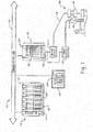
- the industrial control system 110 utilizes programmable input/output (I/O) circuits that are described in greater detail below. It should be noted that the industrial control system 110 is merely one example of an industrial control system that could utilize the present invention, and that other systems are also possible.
- I/O input/output
- the industrial control system 110 comprises a programmable control system 112 that controls the output status of a plurality of output devices 114 based on the input status of a plurality of input devices 116.
- the programmable control system 112 has a microprocessor-based processor module 117 that executes a stored control program which defines the manner in which the output devices 114 are controlled.
- the processor module 117 communicates with the I/O devices 114 and 116 by way of an I/O module 118.
- the processor module 117 transmits a digital representation of the desired output status of the output devices 114 to the I/O module 118.
- the I/O module 118 Based on the digital representation of the desired output status of the output devices 114, the I/O module 118 produces an output control signal that is capable of driving the output devices 114 in the desired manner.
- the processor module 117 receives a digital representation of the input status of the input devices 116 from the I/O module 118.
- the I/O module 118 produces the digital representation of the input status of the input devices 116 based on input status signals received from the input devices 116.
- the processor module 117 is disposed in a rack 119 and the I/O module 118 is disposed in a separate rack 122, and communication between the processor module 117 and the I/O module 118 occurs by way of a Remote I/O network or other communication link 123.
- the industrial control system 110 further comprises a communication module 124 and a communication module 125.
- the communication module 124 is mounted in the same rack 119 as the processor module 117 and communication between the two modules occurs by way of a common backplane that is incorporated into the rack 119.
- the communication module 125 is mounted in the same rack as the I/O module 118 and communication between the two occurs by way of a common backplane that is incorporated into the rack 122.
- processor module 117 may communicate directly to communication module 125 if processor module 117 includes inherent communication port supporting communication link.
- information is transmitted from the processor module 117 to the I/O module 118 through the backplane of the rack 119, through the communication module 124, through the communication link 123, through the communication module 125, and through the backplane of the rack 122.
- Information is transmitted from the I/O module 118 to the processor module 117 by way of the opposite path.
- communication modules 124 and 125 may be, but are not limited to, a scanner module, adapter module, Ethernet adapter, Ethernet port, etc.
- the industrial control system 110 also comprises other features such as an operator interface 128 and a message display 130.
- the operator interface 128 and message display 130 facilitate human interaction with the industrial control system 110.
- the rack 119 contains a plurality of other modules 132.
- the other modules 132 could include, for example, one or more Ethernet modules, Data Highway or Data Highway Plus modules, and/or a plurality of other types of modules, all of which plug into the same common backplane.
- the I/O rack 122 contains a plurality of additional I/O modules 134.
- the I/O module 118 could be disposed in the same rack 119 as the processor module 117.
- an industrial control system could be implemented without using rack-mounted modules.
- the I/O module 118 transmits the analog output control signals to the output devices 114 and receives the analog input status signals from the input devices 116.
- the I/O module 118 includes digital-to-analog (D/A) converters (not illustrated) that convert digital representations of desired output status received from the processor module 117 by way of the communication link 123 to signals that are used as inputs to I/O circuits. The I/O circuits use these inputs to produce analog output control signals to control the output devices 114.
- I/O module 118 also includes analog-to-digital AID converters (not illustrated) that convert outputs of I/O circuits into digital representations of the input status that can be transmitted by way of the communication link 123 to the processor module 117. The outputs of the I/O circuits are produced based upon the analog input status signals received from the input devices 116.
- a controlled safety process 140 includes a light curtain 142 providing redundant light curtain signals 144 to the I/O module 118 and a press 146 that may be stopped via a halt signal 148 sent to the press 146 from the I/O module 118.
- the safety process 140 is designed to stop the press 146 if the plane of the light curtain 142 is crossed.
- the speed of response, i.e., the safety reaction time, of the I/O module 118 in halting the press 146 after an object cross the plane of the light curtain 142 is factored into the calculation to determine the required amount of separation between the light curtain 142 and the press 146.
- processor module 117 includes a primary processing unit 250a communicating via a communication protocol to a partner processing unit 250b, which can include serial or parallel communications.
- Primary processing unit 250a includes a first, or controlling processor, or CPU, 252a and a system clock 253a, both of which are driven by a single clock source 254a.
- the system clock 253a increments in one microsecond intervals.
- the CPU 252a has an internal ROM 256a (read only memory) which holds an executive, or firmware, image 258a of executables 260a comprised of safety critical functions 261a, diagnostic code 262a, and non-safety functions 263a.
- internal ROM 256a may be external to CPU 252a and operatively associated with CPU 252a.
- CPU 252a further includes a flag 264a and a timer interrupt function implemented with a compare register 266a wherein the compare register 266a is loaded with a preset time value. When the system clock 253a reaches the value stored in the compare register 266a, CPU 252a will interrupt the execution of the executive image 258a.
- Partner processing unit 250b includes mostly the same, though independent, components including a processor 252b and system clock 253b driven by a single clock source 254b, ROM 256b, firmware image 258b of slightly different executables 260b comprised of safety critical functions 261b, diagnostic code 262b and non-safety functions 263b, flag 264b and compare register 266b providing the same timer interrupt functionality.
- FIG. 3 is a block diagram of an industrial controller including watchdog interface circuitry according to an exemplary embodiment of this disclosure.
- primary processing unit 250a associated with a Primary Safety Controller (PSC) includes a CPU 302 operatively associated with a fault signal line 322, the fault signal line 322 operatively associated with an integrated logic circuit configured as a voltage monitor, such as a FPGA, and configured to disable external I/O communications, i.e., communication link such as Ethernet port 1308 and Ethernet port 2 310, in the event a fault is detected by CPU 302 during the execution of a safety task scan, loop, or other routine which determines a fault condition with one or more processes.
- Primary processing unit 250a also includes buffer 304 and communication channel 318 which are integrated with secondary processing unit 250b.
- Secondary processing unit 250b associated with a Safety Partner Controller (SPC), includes a CPU 312 (redundant watchdog) operatively associated with a fault signal line 324, a Dual-Port SRAM 314, and communication channel 320 operatively associated with data communications between Dual-Port SRAM 314 and CPU 312.
- Dual-Port SRAM 314 is operatively connected to CPU 302 of the primary processing unit 250a via communication channel 318, the Dual-Port SRAM providing the necessary data communication and storage between the first processing unit 250a and secondary processing unit 250b to execute independent safety task scans/loops, and also perform watchdog functions configured to monitor the health, i.e., operational state, of the other CPU.
- Dual-Port SRAM 314 may be any communication medium, and/or interface, such as but not limited to, backplane, buffer, etc.
- a safety I/O message is constructed by CPU 302, wrapped with a CST and passed to the second CPU 312, via Dual-Port SRAM 314, for validation by the second CPU 312.
- CPU 312 determines the CST is outside an expected range or another routine determines a fault condition with one or more processes
- CPU 312 generates a fault via fault line 324 which directly disables communications link, i.e., Ethernet port 1 308 and Ethernet port 2 310, with any externally controlled devices, such as I/O modules which control and monitor a safety process.
- the direct control of I/O communications by CPU 312 is provided by watchdog communication channel including buffer 316, interface 326, buffer 304, integrated logic circuitry 306 and controls, e.g., reset, power, etc., provided by communication channel 330.
- Watchdog communication channel includes indications of CPU 312 status, e.g., reset status, fault, providing redundant communication channels between PSC CPU 302 and SPC CPU 312.
- redundant watchdog communication channel provides status information of CPU 312 to disable safety communication link through communication port 308, 310
- Watchdog communication channel 326 could utilize parallel or serial communication protocol, e.g., SPI (Serial Peripheral Interface), SCI (Serial Communications Interface), UART (Universal Asynchronous Receiver/Transmitter), etc., while integrated logic circuitry 306 performs affirmation of SPC fault, integrated logic circuitry 306 shutdowns/disables the communication ports 308, 310.
- SPI Serial Peripheral Interface
- SCI Serial Communications Interface
- UART Universal Asynchronous Receiver/Transmitter
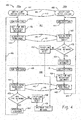
- FIG. 4 is a visual representation of a process wherein processor Module 117 performs a safety timer cross-check diagnostic 400 beginning at start blocks 404, 408 representing a "safety loop" initialization process, according to an exemplary embodiment of this disclosure.
- the safety loop initialization process serves two functions; it ensures that both CPUs 252a, 252b have interrupts loaded prior to entry of the safety loop and it also synchs up the two CPUs 252a, 252b to begin the safety loop at the same time. This synching is shown by a rendezvous message 406 and an acknowledgement message 410 between the two processing units 250a, 250b.
- timer compare registers 266a, 266b are used to generate the interrupts in CPUs 252a, 252b.
- the first interrupt is scheduled in CPU 252a, acting as controlling CPU, by loading compare register 266a with a value representing the 6 ms from when the previous interrupt was scheduled to occur.
- the 6 ms time period represents the rated safety reaction time of the I/O module 118.
- An interrupt is also scheduled in CPU 252b, acting as monitoring CPU, to occur at a time slightly longer than the 6 ms time loaded into CPU 252a.
- the extra time acts as a cushion or tolerance and is necessary due to the slight delay between CPU 252a being interrupted and processing unit 250a sending a rendezvous message to processing unit 250b as well as to allow for slight time differences between the processing units 250a, 250b.
- processing units 250a, 250b After the interrupts have been scheduled, i.e., after the timer compare registers 266a, 266b have been loaded, processing units 250a, 250b have essentially begun executing a first safety loop 427.
- processing unit 250a acts as the controlling unit while partner processing unit 250b acts as the monitoring unit.
- CPUs 252a, 252b in each processing unit 250a, 250b process the executables 260a, 260b, including safety critical functions 261a, 261b and non-safety functions 263a, 263b.
- an internal flag 264a is set, This flag indicates that the safety critical functions 261a, have been completed by the controlling CPU 252a within the rated safety reaction time. Thereafter, CPU 252a executes non-safety functions 263a while waiting for the timer interrupt, shown as block 416. Meanwhile, CPU 252b finishes executing safety critical functions 261b, sets flag 264b and begins executing non-safety functions 263b while waiting for either rendezvous message 420 from processing unit 250a or for its own timer interrupt, shown as block 422.
- CPU 252a interrupts the processing of the executive image 258a.
- CPU 252a could repeatedly poll a timer or counter to determine when the time has elapsed.
- this is not the preferred approach as it offers no watchdog function to protect against the case where CPU 252a encounters unexpected delays.
- CPU 252a immediately schedules a new interrupt to occur after another 6 ms plus the cushion have elapsed.
- the cushion is included because CPU 252a becomes the monitoring unit during the next safety loop 428.
- the interrupt is scheduled by loading the compare register 266a with a value representing the next desired interrupt time and is scheduled immediately after the previous interrupt to ensure that processing system 250a is always protected against any unexpected delays.
- CPU 252a next checks whether or not flag 264a is set. If flag 264a is not set, i.e., all the safety critical functions 261a were not completed, a hard or critical fault occurs. Processing unit 250a goes into a safe state and then resets. If the flag 264a is set, a rendezvous signal 420 is sent to processing unit 250b from block 418 to indicate that the time value loaded into compare register 266a, i.e., the safety reaction time of 6 ms, has elapsed as perceived by processing unit 250a.
- processing unit 250b receives the rendezvous signal 420 and promptly replies with an acknowledgement signal 424. In the event of an unexpected delay or inaccurate clock such that CPU 252b is interrupted before receiving rendezvous signal 420, a critical fault will occur wherein the processing unit 250b will go into a safe state and then reset. Otherwise, after receiving rendezvous message 420, CPU 252b checks whether or not flag 264b is set, indicating that all safety functions 261b have been completed. If flag 264b is not set, a critical fault will also occur. If flag 264b is set, processing unit 250b determines whether or not the elapsed safety reaction time, as determined by CPU 252a using clock source 254a, is within the allowable range or cushion (decision block 430). In essence, processing unit 250b is checking the accuracy of clock source 254a by comparing what processing unit 250a determined 6 ms to be against what processing unit 250b, using clock source 254b, determined 6 ms (plus the cushion) to be.
- processing unit 250b If the safety reaction time of processing unit 250a is not within an acceptable range, the processing unit 250b will fault, shown as block 432 and generate a shutdown safety message 456. If the safety reaction time of processing unit 250a is within the acceptable range, processing unit 250b moves to block 434 and schedules the next interrupt. Since CPU 252b will act as the controlling CPU in the next safety loop 428, the value loaded into timer compare register 266b is the value of 6 ms from the current time.
- the roles of the primary processing unit 250a and partner processing unit 250b are reversed wherein the primary processing unit 250a becomes the monitoring processing unit while partner processing unit 250b becomes the controlling processing unit.
- This symmetry i.e., role-swapping, is useful because at this point in the diagnostic 400, only the clock source 254a of primary processing unit 250a has been verified as being accurate.
- the diagnostic 400 ensures that both CPUs 252a, 252b have the ability to accurately measure time as well as the ability to interrupt to generate a fault.
- CPUs 252a, 252b of each processing unit 250a, 250b process the executables 260a, 260b, including safety critical functions 261a, 261b again. After completing the safety functions 261a, 261b, internal flags 264a, 264b are set. Thereafter, CPU 252b waits for its timer interrupt shown as block 438 while CPU 252a waits for either rendezvous message 442 from processing unit 250b or for its own timer interrupt.
- CPU 252b interrupts processing. After the interrupt, the CPU 252b immediately schedules a new interrupt (with cushion) to prepare for monitoring, as previously discussed. Next, CPU 252b checks whether or not the flag 264b is set. If flag 264b is not set, a critical fault occurs in processing unit 250b which goes to a safe state and then resets.
- a rendezvous signal 442 is sent to processing unit 250a to indicate that the time loaded into compare register 266b, i.e., the safety reaction time of 6 ms, has elapsed as determined by processing unit 250b using clock source 254b.
- Processing unit 250a meanwhile receives signal 442 (block 444) and promptly replies with acknowledgement signal 446.
- Processing unit 250b enters a new safety loop and begins processing safety functions 261a (shown as return path 448 to safety loop 427).
- CPU 252a In the event that CPU 252a is interrupted before receiving rendezvous signal 442, (as a result of an unexpected delay or inaccurate clock), a critical fault occurs wherein the processing unit 250a will go to a safe state and then reset. After receiving rendezvous signal 442, CPU 252a checks whether or not flag 264a is set. If flag 264a is not set, a critical fault would also occur. If flag 264a is set, processing unit 250a (decision block 450) determines whether or not the elapsed safety reaction time, as calculated by CPU 252b using clock source 254b, is within the allowable range or cushion.
- processing unit 250a If the safety reaction time, as determined using clock source 254a, is not within the acceptable range, the processing unit 250a will fault, shown as block 452 and generate a shutdown safety message 456. If the safety reaction time is within the acceptable range, processing 250a unit moves to block 454 where the next interrupt is scheduled. Since 252a will be the controlling CPU again, the value loaded into timer compare register 266a would be 6 ms from the time the last interrupt was scheduled by CPU 252a, in block 416 (ensuring that the combined time of safety loops 427 and 428 is exactly two safety reaction times, i.e., 12 ms). Processing unit 250a then enters a new safety loop and begins processing safety functions 261a (shown as return path 454 to safety loop 427).
- the safety timer cross-check diagnostic 400 can be repeated at a pre-determined frequency while CPUs 252a, 252b of processing units 250a, 250b continue to perform the executables 260a, 260b, within the safety loops.
- the exemplary embodiment also relates to an apparatus for performing the operations discussed herein.
- This apparatus may be specially constructed for the required purposes, or it may comprise a general-purpose computer selectively activated or reconfigured by a computer program stored in the computer.
- a computer program may be stored in a computer readable storage medium, such as, but is not limited to, any type of disk including floppy disks, optical disks, CD-ROMs, and magnetic-optical disks, read-only memories (ROMs), random access memories (RAMs), EPROMs, EEPROMs, magnetic or optical cards, or any type of media suitable for storing electronic instructions, and each coupled to a computer system bus.
- a machine-readable medium includes any mechanism for storing or transmitting information in a form readable by a machine (e.g., a computer).
- a machine-readable medium includes read only memory ("ROM”); random access memory (“RAM”); magnetic disk storage media; optical storage media; flash memory devices; and electrical, optical, acoustical or other form of propagated signals (e.g., carrier waves, infrared signals, digital signals, etc.), just to mention a few examples.
- the methods illustrated throughout the specification may be implemented in a computer program product that may be executed on a computer.
- the computer program product may comprise a non-transitory computer-readable recording medium on which a control program is recorded, such as a disk, hard drive, or the like.
- a non-transitory computer-readable recording medium such as a disk, hard drive, or the like.
- Common forms of non-transitory computer-readable media include, for example, floppy disks, flexible disks, hard disks, magnetic tape, or any other magnetic storage medium, CD-ROM, DVD, or any other optical medium, a RAM, a PROM, an EPROM, a FLASH-EPROM, or other memory chip or cartridge, or any other tangible medium from which a computer can read and use.
- the method may be implemented in transitory media, such as a transmittable carrier wave in which the control program is embodied as a data signal using transmission media, such as acoustic or light waves, such as those generated during radio wave and infrared data communications, and the like.
- transitory media such as a transmittable carrier wave
- the control program is embodied as a data signal using transmission media, such as acoustic or light waves, such as those generated during radio wave and infrared data communications, and the like.
Landscapes
- Engineering & Computer Science (AREA)
- Physics & Mathematics (AREA)
- General Physics & Mathematics (AREA)
- Theoretical Computer Science (AREA)
- Automation & Control Theory (AREA)
- Quality & Reliability (AREA)
- General Engineering & Computer Science (AREA)
- Hardware Redundancy (AREA)
Claims (9)
- Industrielle Automatisierungssteuerung, umfassend:eine erste Verarbeitungseinheit (250a) mit einem ersten Prozessor (252a, 302), einem ersten Speicher, einer ersten Taktquelle (254a) und einem ersten Fehleranzeigesignal (322), wobei die erste Verarbeitungseinheit eingerichtet ist, eine erste Sicherheitsschleife auszuführen (427; 404, 412, 416, 418);eine zweite Verarbeitungseinheit (250b) mit einem zweiten Prozessor (252b, 312), einem zweiten Speicher, einer zweiten Taktquelle (254b) und einem zweiten Fehleranzeigesignal (324), wobei die zweite Verarbeitungseinheit eingerichtet ist, eine zweite Sicherheitsschleife auszuführen (427; 414, 422, 430, 432, 434);eine Kommunikationsverbindung, die eingerichtet ist, eine Statusinformation zwischen der ersten Verarbeitungseinheit und der zweiten Verarbeitungseinheit bereitzustellen;eine Kommunikationsvorrichtung (308, 310), die mit Eingabe/Ausgabe-, E/A-Kommunikationen zwischen der ersten Verarbeitungseinheit und einer oder mehreren entfernten Vorrichtungen betriebsmäßig zusammenhängt; undeinen Handler, der mit der ersten Verarbeitungseinheit und der zweiten Verarbeitungseinheit betriebsmäßig zusammenhängt, wobei der Handler eingerichtet ist, als Eingaben das erste Fehleranzeigesignal und das zweite Fehleranzeigesignal zu empfangen,dadurch gekennzeichnet, dass:der Handler eine integrierte Schaltung (306) ist, unddie integrierte Schaltung ferner eingerichtet ist zum:Bereitstellen von Datenkommunikationen zwischen dem ersten Prozessor und der Kommunikationsvorrichtung, undAbschalten der E/A-Kommunikationen, falls das zweite Fehleranzeigesignal einen Fehlerzustand darstellt, der mit der Ausführung der zweiten Sicherheitsschleife zusammenhängt.
- Industrielle Automatisierungssteuerung nach Anspruch 1, wobei die erste und die zweite Sicherheitsschleife Folgendes umfassen:eine Synchronisationsroutine, die sowohl von der ersten (250a) als auch von der zweiten Verarbeitungseinheit (250b) ausgeführt wird, um den Start der Ausführung der ersten und der zweiten Sicherheitsschleife zu synchronisieren; undeine Diagnoseroutine, die sowohl von der ersten als auch von der zweiten Verarbeitungseinheit ausgeführt wird.
- Industrielle Automatisierungssteuerung nach Anspruch 2, umfassend:
eine Sicherheitsaufgaben-Scan-Routine, die von der ersten Verarbeitungseinheit (250a) ausgeführt wird, wobei die Sicherheitsaufgaben-Scan-Routine eine Sicherheits-E/A-Nachricht erzeugt, die mit einer Koordinatensystemzeit, CST, umhüllt ist und an die zweite Verarbeitungseinheit (250b) zur Validierung durch die zweite Verarbeitungseinheit übergeben wird. - Industrielle Automatisierungssteuerung nach Anspruch 1, wobei die integrierte Schaltung ein Field Programmable Gate Array, FPGA, ist.
- Verfahren zum Betreiben einer industriellen Automatisierungssteuerung, umfassend:eine erste Verarbeitungseinheit (250a) und eine zweite Verarbeitungseinheit (250b),wobei die erste Verarbeitungseinheit einen ersten Prozessor (252a, 302), einen ersten Speicher, eine erste Taktquelle (254a) und ein erstes Fehleranzeigesignal (322) umfasst,wobei die zweite Verarbeitungseinheit einen zweiten Prozessor (242b, 312), einen zweiten Speicher, eine zweite Taktquelle (254b) und ein zweites Fehleranzeigesignal (324) umfasst,den ersten und den zweite Speicher ladbar mit jeweils einem ersten und einem zweiten Sicherheitsprogramm und Eingabe-/Ausgabevariablen,wobei die Sicherheitsprogramme wiederholt ausführbar sind, um Eingangsvariablen zu lesen, die Eingaben von einem oder mehreren entfernten Vorrichtungen darstellen, und um Ausgangsvariablen zu schreiben, die Ausgaben an ein oder mehrere entfernte Vorrichtungen darstellen, und einen Handler, der betriebsmäßig mit der ersten Verarbeitungseinheit und der zweiten Verarbeitungseinheit zusammenhängt,das Verfahren umfassend:a) Synchronisieren des ersten und des zweiten Prozessors;b) Laden des ersten und des zweiten Prozessors mit jeweils einer ersten und einer zweiten vorbestimmten Unterbrechungszeit;c) Ausführen einer ersten Sicherheitsschleife (427; 404, 412, 416, 418) durch die erste Verarbeitungseinheit und Ausführen einer zweiten Sicherheitsschleife (427; 414, 422, 430, 432, 434) durch die zweite Verarbeitungseinheit, wobei die erste Verarbeitungseinheit eine Sicherheits-E/A-Nachricht erzeugt, die zur Validierung durch die zweite Verarbeitungseinheit an die zweite Verarbeitungseinheit weitergeleitet wird; unde) Unterbrechen des ersten Prozessors nach Ablauf der ersten Unterbrechungszeit basierend auf einer Eingabe von der ersten Taktquelle,dadurch gekennzeichnet, dass:die E/A-Sicherheitsnachricht mit einer Koordinatensystemzeit, CST, basierend auf der ersten Taktquelle umhüllt ist,das Verfahren ferner umfasst:
d) wenn die CST nicht innerhalb eines vorbestimmten Wertebereichs liegt, Erzeugen, durch die zweite Verarbeitungseinheit, des zweiten Fehleranzeigesignal, das mit einem Abschalten von Kommunikationen mit einem oder mehreren entfernten Vorrichtungen zusammenhängt;der Handler eine integrierte Schaltung (306) ist; unddie integrierte Schaltung eingerichtet ist zum Abschalten von Kommunikationen zwischen der ersten Verarbeitungseinheit und der einen oder den mehreren entfernten Vorrichtungen, falls das zweite Fehleranzeigesignal einen Fehlerzustand darstellt, der mit einer Ausführung der zweiten Sicherheitsschleife zusammenhängt. - Verfahren zum Betreiben einer industriellen Automatisierungssteuerung nach Anspruch 5, ferner umfassend:f) erneutes Synchronisieren des ersten (252a, 302) und des zweiten Prozessors (252b, 312);g) erneutes Laden des ersten und des zweiten Prozessors mit vorbestimmten Unterbrechungszeiten;h) Ausführen mindestens einer Schleife beider Sicherheitsprogramme;i) Unterbrechen des zweiten Prozessors nach Ablauf der zweiten Unterbrechungszeit basierend auf der Eingabe von der zweiten Taktquelle (254b) und Senden eines Signals an die erste Verarbeitungseinheit (250a); undj) Bestimmen, durch die erste Verarbeitungseinheit, ob die von der ersten Verarbeitungseinheit gemessene zweite Unterbrechungszeit im Wesentlichen der von der zweiten Verarbeitungseinheit gemessenen Zeit für die zweite Unterbrechung entspricht (250b).
- Verfahren zum Betreiben einer industriellen Automatisierungssteuerung nach Anspruch 5, wobei die integrierte Schaltung (306) ein Field Programmable Gate Array, FPGA, ist.
- Steuerungsmodul, umfassend:eine erste Verarbeitungseinheit (250a) mit einem ersten Prozessor (252a, 302), der von einer ersten Taktquelle (254a) angetrieben wird;eine zweite Verarbeitungseinheit (250b) mit einem zweiten Prozessor (252b, 312), der von dem ersten Prozessor unabhängig ist und von einer zweiten Taktquelle (254b) angetrieben wird, die von der ersten Taktquelle unabhängig ist, wobei der zweite Prozessor mit dem ersten Prozessor synchronisiert ist;einen Handler, der betriebsmäßig mit der ersten Verarbeitungseinheit und der zweiten Verarbeitungseinheit zusammenhängt; undeine Diagnose, die in der ersten und zweiten Verarbeitungseinheit abläuft,wobei die Diagnose eingerichtet ist zum:Validieren der Genauigkeit jeder Taktquelle, undanfänglichen Zuweisen des ersten Prozessors als Steuerprozessor und des zweiten Prozessors als Überwachungsprozessor, wobei der Überwachungsprozessor eingestellt ist unterbrochen zu werden, nachdem der Steuerprozessor eingestellt ist unterbrochen zu werden,dadurch gekennzeichnet, dass:die zweite Verarbeitungseinheit eingerichtet ist eine Koordinatensystemzeit, CST zu validieren, die mit einer von der ersten Verarbeitungseinheit bereitgestellten Sicherheits-E/A-Nachricht zusammenhängtder Handler eine integrierte Schaltung (306) ist, unddie integrierte Schaltung eingerichtet ist Kommunikationen zwischen der ersten Verarbeitungseinheit und einem oder mehreren zugeordneten entfernten Vorrichtungen abzuschalten, wenn die CST-Zeit nicht innerhalb eines vorbestimmten Wertebereichs liegt.
- Steuerungsmodul nach Anspruch 8, wobei:nachdem der Steuerprozessor unterbrochen ist, der Steuerprozessor ein Signal an den Überwachungsprozessor sendet;der Überwachungsprozessor die Genauigkeit der Taktquelle des Steuerungsprozessors überprüft;das Modul in einen Sicherheitszustand übergeht, wenn der Überwachungsprozessor feststellt, dass die Genauigkeit der Taktquelle des Steuerungsprozessors nicht innerhalb eines voreingestellten Bereichs liegt;der erste und der zweite Prozessor die Rollen wechseln und eine Schleife jedes Sicherheitsprogramms erneut ausgeführt wird;die integrierte Schaltung ein Field Programmable Gate Array, FPGA, ist.
Applications Claiming Priority (1)
| Application Number | Priority Date | Filing Date | Title |
|---|---|---|---|
| US14/604,046 US9632492B2 (en) | 2015-01-23 | 2015-01-23 | Redundant watchdog method and system utilizing safety partner controller |
Publications (2)
| Publication Number | Publication Date |
|---|---|
| EP3048499A1 EP3048499A1 (de) | 2016-07-27 |
| EP3048499B1 true EP3048499B1 (de) | 2020-01-15 |
Family
ID=55221343
Family Applications (1)
| Application Number | Title | Priority Date | Filing Date |
|---|---|---|---|
| EP16152331.1A Active EP3048499B1 (de) | 2015-01-23 | 2016-01-22 | Redundantes überwachungsverfahren und system mit sicherheitspartnersteuerung |
Country Status (2)
| Country | Link |
|---|---|
| US (2) | US9632492B2 (de) |
| EP (1) | EP3048499B1 (de) |
Families Citing this family (17)
| Publication number | Priority date | Publication date | Assignee | Title |
|---|---|---|---|---|
| JP6361822B2 (ja) * | 2015-05-11 | 2018-07-25 | 村田機械株式会社 | 自動運転機器システム、非常停止端末、及び操作端末の制御方法 |
| KR102337044B1 (ko) * | 2015-07-27 | 2021-12-09 | 에스케이하이닉스 주식회사 | 반도체장치 및 반도체시스템 |
| EP3267270B1 (de) * | 2016-07-05 | 2022-01-19 | Siemens Aktiengesellschaft | Fehlersicheres automatisierungssystem |
| WO2018023110A1 (en) | 2016-07-29 | 2018-02-01 | Hubbell Incorporated | Self-diagnostic fault identification system for emergency lighting unit |
| JP6812737B2 (ja) * | 2016-10-07 | 2021-01-13 | オムロン株式会社 | 演算装置および制御装置 |
| DE202016007417U1 (de) * | 2016-12-03 | 2018-03-06 | WAGO Verwaltungsgesellschaft mit beschränkter Haftung | Steuerung Redundanter Verarbeitungseinheiten |
| EA034974B1 (ru) * | 2017-10-24 | 2020-04-13 | Акционерное общество "ТеконГруп" | Способ обеспечения функциональной безопасности модуля центрального процессора промышленного контроллера и микропроцессорная система для осуществления данного способа (варианты) |
| JP2019179476A (ja) * | 2018-03-30 | 2019-10-17 | オムロン株式会社 | サポート装置、サポートプログラム、設定方法 |
| US10466220B1 (en) | 2018-09-21 | 2019-11-05 | Pace Analytical Services, LLC | Alerting for instruments that transfer physical samples |
| DE102018220301A1 (de) * | 2018-11-26 | 2020-05-28 | Festo Ag & Co. Kg | Kommunikationseinheit, Steuergerät, Kommunikationssystem und Verfahren |
| CN112558505B (zh) * | 2019-09-10 | 2024-10-15 | 阿里(四川)网络技术有限公司 | 工控系统的控制处理方法、装置、工控系统及电子设备 |
| DE102019217427A1 (de) * | 2019-11-12 | 2021-05-12 | Kuka Deutschland Gmbh | Steuern und/oder Überwachen einer Maschinenanordnung |
| US20240231301A1 (en) * | 2021-05-04 | 2024-07-11 | Abb Schweiz Ag | Safety network for devices in intermittent use |
| EP4095689B1 (de) * | 2021-05-28 | 2025-08-27 | Bayerische Motoren Werke Aktiengesellschaft | Überwachung eines zeitplans eines auf einer steuereinheit laufenden ersten threads |
| CN115022159A (zh) * | 2022-06-27 | 2022-09-06 | 汉中一零一航空电子设备有限公司 | 一种控制设备主控制器冗余备份系统及方法 |
| WO2025048768A1 (en) * | 2023-08-25 | 2025-03-06 | Siemens Aktiengesellschaft | Safety related shutdown for functionally non-safe standard modules |
| US12468596B2 (en) | 2024-04-18 | 2025-11-11 | Rockwell Collins, Inc. | Temporal buffering of integrity comparison data |
Family Cites Families (24)
| Publication number | Priority date | Publication date | Assignee | Title |
|---|---|---|---|---|
| US4472789A (en) | 1979-11-09 | 1984-09-18 | General Signal Corporation | Vital timer |
| US5455935A (en) | 1991-05-31 | 1995-10-03 | Tandem Computers Incorporated | Clock synchronization system |
| JPH064353A (ja) | 1992-06-17 | 1994-01-14 | Sumitomo Electric Ind Ltd | 複数のマイクロコンピュータの相互監視回路 |
| KR950005940B1 (ko) | 1992-12-29 | 1995-06-07 | 재단법인한국전자통신연구소 | 클럭 감시 회로 |
| SE9702176L (sv) | 1997-06-06 | 1998-12-07 | Ericsson Telefon Ab L M | En maskinvarukonstruktion för majoritetsval, samt test och underhåll av majoritetsval |
| US6298393B1 (en) | 1998-09-30 | 2001-10-02 | Rockwell Technologies, Llc | Industrial control systems having input/output circuits with programmable input/output characteristics |
| US6359858B1 (en) | 1999-06-03 | 2002-03-19 | Fujitsu Network Communications, Inc. | Switching redundancy control |
| AU5451100A (en) | 1999-06-09 | 2000-12-28 | Worldstream Communications, Inc. | Metered content delivery |
| US6909923B2 (en) | 1999-12-22 | 2005-06-21 | Rockwell Automation Technologies, Inc. | Safety communication on a single backplane |
| DE10056408C1 (de) | 2000-11-14 | 2002-03-07 | Bosch Gmbh Robert | Vorrichtung zur Überwachung eines Prozessors |
| US7089462B2 (en) | 2003-04-17 | 2006-08-08 | International Business Machines Corporation | Early clock fault detection method and circuit for detecting clock faults in a multiprocessing system |
| US7328370B2 (en) | 2003-09-12 | 2008-02-05 | Rockwell Automation Technologies, Inc. | Safety controller with simplified interface |
| US7287184B2 (en) | 2003-09-16 | 2007-10-23 | Rockwell Automation Technologies, Inc. | High speed synchronization in dual-processor safety controller |
| US7213168B2 (en) | 2003-09-16 | 2007-05-01 | Rockwell Automation Technologies, Inc. | Safety controller providing for execution of standard and safety control programs |
| US7117048B2 (en) | 2003-09-30 | 2006-10-03 | Rockwell Automation Technologies, Inc. | Safety controller with safety response time monitoring |
| GB0428038D0 (en) | 2004-12-22 | 2005-01-26 | Ibm | Measuring elapsed time for a software routine |
| US7186918B2 (en) | 2005-04-07 | 2007-03-06 | Wolf Appliance Company, Llc | Rotatable cover plate |
| US7617412B2 (en) | 2006-10-25 | 2009-11-10 | Rockwell Automation Technologies, Inc. | Safety timer crosscheck diagnostic in a dual-CPU safety system |
| IT1391785B1 (it) * | 2008-11-21 | 2012-01-27 | St Microelectronics Srl | Sistema elettronico per il rilevamento di un guasto |
| US8334707B2 (en) * | 2008-12-29 | 2012-12-18 | Infineon Technologies Ag | Storage circuit with fault detection and method for operating the same |
| US8423823B2 (en) * | 2010-12-22 | 2013-04-16 | Ge Energy Power Conversion Technology Limited | Communications architecture for providing data communication, synchronization and fault detection between isolated modules |
| US8516355B2 (en) | 2011-02-16 | 2013-08-20 | Invensys Systems, Inc. | System and method for fault tolerant computing using generic hardware |
| US8731002B2 (en) * | 2011-03-25 | 2014-05-20 | Invensense, Inc. | Synchronization, re-synchronization, addressing, and serialized signal processing for daisy-chained communication devices |
| US8850092B2 (en) | 2011-04-11 | 2014-09-30 | Rockwell Automation Technologies, Inc. | Input module for an industrial controller |
-
2015
- 2015-01-23 US US14/604,046 patent/US9632492B2/en active Active
-
2016
- 2016-01-22 EP EP16152331.1A patent/EP3048499B1/de active Active
-
2017
- 2017-04-17 US US15/488,893 patent/US9964937B2/en active Active
Non-Patent Citations (1)
| Title |
|---|
| None * |
Also Published As
| Publication number | Publication date |
|---|---|
| US9632492B2 (en) | 2017-04-25 |
| US20170220015A1 (en) | 2017-08-03 |
| EP3048499A1 (de) | 2016-07-27 |
| US20160216704A1 (en) | 2016-07-28 |
| US9964937B2 (en) | 2018-05-08 |
Similar Documents
| Publication | Publication Date | Title |
|---|---|---|
| EP3048499B1 (de) | Redundantes überwachungsverfahren und system mit sicherheitspartnersteuerung | |
| EP1916581B1 (de) | Sicherheits-Gegenprobendiagnose in einem Sicherheitssystem mit zwei Zentralprozessoren | |
| US8909971B2 (en) | Clock supervision unit | |
| US10006455B2 (en) | Drive control apparatus | |
| US20150120009A1 (en) | Independent Operation of Control Hardware and a Monitoring System in an Automation Controller | |
| US10452033B2 (en) | Process control system | |
| EP2685334A2 (de) | Sicherheitssystem und Steuervorrichtung | |
| NO331420B1 (no) | Fremgangsmåte og midler for å øke sikkerhetsintegritets¬nivået til et kontrollsystem | |
| US20130131832A1 (en) | Method and Apparatus For Analogue Output Current Control | |
| US20120221897A1 (en) | Method and Device for Performing Failsafe Hardware-Independent Floating-Point Arithmetic | |
| CN102651044B (zh) | 一种仿真节点、多余度仿真计算机系统及方法 | |
| MX2015001900A (es) | Metodos y aparatos para reducir las fallas de modo comun en los sistemas de control de software relacionados con la seguridad nuclear. | |
| KR102438148B1 (ko) | 임베디드 컴퓨팅 모듈의 이상을 감지하는 이상 감지 장치, 시스템 및 방법 | |
| CA2874995A1 (en) | Method for verifying the processing of software | |
| JP7267400B2 (ja) | 安全性が要求されるプロセスを監視する自動化システム | |
| JP4102814B2 (ja) | 入出力制御装置,情報制御装置及び情報制御方法 | |
| US20250348053A1 (en) | System and Method for Virtualization of Distributed Motion and Safety | |
| EP4299261B1 (de) | Gerätesteuerungssystem, gerätesteuerungsverfahren und gerätesteuerungsprogramm | |
| CN103154837B (zh) | 用于自动化系统的过程冗余控制的方法 | |
| US10969819B2 (en) | Security control and method for operating a security control | |
| Ždánsky et al. | Influence of architecture and parameters of SRCS on Safety function response time | |
| Ždánsky et al. | Problems related to the two-channel connection of sensors to the safety PLC | |
| Konuk | Redundant and safe work implementation for S7-1200 PLC family | |
| EA034974B1 (ru) | Способ обеспечения функциональной безопасности модуля центрального процессора промышленного контроллера и микропроцессорная система для осуществления данного способа (варианты) | |
| HK1195138B (en) | Method for operating a safety control device |
Legal Events
| Date | Code | Title | Description |
|---|---|---|---|
| PUAI | Public reference made under article 153(3) epc to a published international application that has entered the european phase |
Free format text: ORIGINAL CODE: 0009012 |
|
| AK | Designated contracting states |
Kind code of ref document: A1 Designated state(s): AL AT BE BG CH CY CZ DE DK EE ES FI FR GB GR HR HU IE IS IT LI LT LU LV MC MK MT NL NO PL PT RO RS SE SI SK SM TR |
|
| AX | Request for extension of the european patent |
Extension state: BA ME |
|
| STAA | Information on the status of an ep patent application or granted ep patent |
Free format text: STATUS: REQUEST FOR EXAMINATION WAS MADE |
|
| 17P | Request for examination filed |
Effective date: 20170123 |
|
| RBV | Designated contracting states (corrected) |
Designated state(s): AL AT BE BG CH CY CZ DE DK EE ES FI FR GB GR HR HU IE IS IT LI LT LU LV MC MK MT NL NO PL PT RO RS SE SI SK SM TR |
|
| STAA | Information on the status of an ep patent application or granted ep patent |
Free format text: STATUS: EXAMINATION IS IN PROGRESS |
|
| 17Q | First examination report despatched |
Effective date: 20180323 |
|
| GRAP | Despatch of communication of intention to grant a patent |
Free format text: ORIGINAL CODE: EPIDOSNIGR1 |
|
| STAA | Information on the status of an ep patent application or granted ep patent |
Free format text: STATUS: GRANT OF PATENT IS INTENDED |
|
| RIC1 | Information provided on ipc code assigned before grant |
Ipc: G05B 23/02 20060101ALI20190731BHEP Ipc: G06F 11/07 20060101ALI20190731BHEP Ipc: G06F 11/16 20060101ALI20190731BHEP Ipc: G05B 19/042 20060101AFI20190731BHEP Ipc: G05B 9/03 20060101ALI20190731BHEP |
|
| INTG | Intention to grant announced |
Effective date: 20190821 |
|
| GRAS | Grant fee paid |
Free format text: ORIGINAL CODE: EPIDOSNIGR3 |
|
| GRAA | (expected) grant |
Free format text: ORIGINAL CODE: 0009210 |
|
| STAA | Information on the status of an ep patent application or granted ep patent |
Free format text: STATUS: THE PATENT HAS BEEN GRANTED |
|
| AK | Designated contracting states |
Kind code of ref document: B1 Designated state(s): AL AT BE BG CH CY CZ DE DK EE ES FI FR GB GR HR HU IE IS IT LI LT LU LV MC MK MT NL NO PL PT RO RS SE SI SK SM TR |
|
| REG | Reference to a national code |
Ref country code: CH Ref legal event code: EP Ref country code: GB Ref legal event code: FG4D |
|
| REG | Reference to a national code |
Ref country code: IE Ref legal event code: FG4D |
|
| REG | Reference to a national code |
Ref country code: DE Ref legal event code: R096 Ref document number: 602016028148 Country of ref document: DE |
|
| REG | Reference to a national code |
Ref country code: AT Ref legal event code: REF Ref document number: 1225698 Country of ref document: AT Kind code of ref document: T Effective date: 20200215 |
|
| REG | Reference to a national code |
Ref country code: NL Ref legal event code: MP Effective date: 20200115 |
|
| REG | Reference to a national code |
Ref country code: LT Ref legal event code: MG4D |
|
| PG25 | Lapsed in a contracting state [announced via postgrant information from national office to epo] |
Ref country code: NL Free format text: LAPSE BECAUSE OF FAILURE TO SUBMIT A TRANSLATION OF THE DESCRIPTION OR TO PAY THE FEE WITHIN THE PRESCRIBED TIME-LIMIT Effective date: 20200115 Ref country code: RS Free format text: LAPSE BECAUSE OF FAILURE TO SUBMIT A TRANSLATION OF THE DESCRIPTION OR TO PAY THE FEE WITHIN THE PRESCRIBED TIME-LIMIT Effective date: 20200115 Ref country code: NO Free format text: LAPSE BECAUSE OF FAILURE TO SUBMIT A TRANSLATION OF THE DESCRIPTION OR TO PAY THE FEE WITHIN THE PRESCRIBED TIME-LIMIT Effective date: 20200415 Ref country code: FI Free format text: LAPSE BECAUSE OF FAILURE TO SUBMIT A TRANSLATION OF THE DESCRIPTION OR TO PAY THE FEE WITHIN THE PRESCRIBED TIME-LIMIT Effective date: 20200115 Ref country code: PT Free format text: LAPSE BECAUSE OF FAILURE TO SUBMIT A TRANSLATION OF THE DESCRIPTION OR TO PAY THE FEE WITHIN THE PRESCRIBED TIME-LIMIT Effective date: 20200607 |
|
| PG25 | Lapsed in a contracting state [announced via postgrant information from national office to epo] |
Ref country code: SE Free format text: LAPSE BECAUSE OF FAILURE TO SUBMIT A TRANSLATION OF THE DESCRIPTION OR TO PAY THE FEE WITHIN THE PRESCRIBED TIME-LIMIT Effective date: 20200115 Ref country code: LV Free format text: LAPSE BECAUSE OF FAILURE TO SUBMIT A TRANSLATION OF THE DESCRIPTION OR TO PAY THE FEE WITHIN THE PRESCRIBED TIME-LIMIT Effective date: 20200115 Ref country code: HR Free format text: LAPSE BECAUSE OF FAILURE TO SUBMIT A TRANSLATION OF THE DESCRIPTION OR TO PAY THE FEE WITHIN THE PRESCRIBED TIME-LIMIT Effective date: 20200115 Ref country code: GR Free format text: LAPSE BECAUSE OF FAILURE TO SUBMIT A TRANSLATION OF THE DESCRIPTION OR TO PAY THE FEE WITHIN THE PRESCRIBED TIME-LIMIT Effective date: 20200416 Ref country code: BG Free format text: LAPSE BECAUSE OF FAILURE TO SUBMIT A TRANSLATION OF THE DESCRIPTION OR TO PAY THE FEE WITHIN THE PRESCRIBED TIME-LIMIT Effective date: 20200415 Ref country code: IS Free format text: LAPSE BECAUSE OF FAILURE TO SUBMIT A TRANSLATION OF THE DESCRIPTION OR TO PAY THE FEE WITHIN THE PRESCRIBED TIME-LIMIT Effective date: 20200515 |
|
| REG | Reference to a national code |
Ref country code: CH Ref legal event code: PL |
|
| REG | Reference to a national code |
Ref country code: BE Ref legal event code: MM Effective date: 20200131 |
|
| REG | Reference to a national code |
Ref country code: DE Ref legal event code: R097 Ref document number: 602016028148 Country of ref document: DE |
|
| PG25 | Lapsed in a contracting state [announced via postgrant information from national office to epo] |
Ref country code: SK Free format text: LAPSE BECAUSE OF FAILURE TO SUBMIT A TRANSLATION OF THE DESCRIPTION OR TO PAY THE FEE WITHIN THE PRESCRIBED TIME-LIMIT Effective date: 20200115 Ref country code: RO Free format text: LAPSE BECAUSE OF FAILURE TO SUBMIT A TRANSLATION OF THE DESCRIPTION OR TO PAY THE FEE WITHIN THE PRESCRIBED TIME-LIMIT Effective date: 20200115 Ref country code: SM Free format text: LAPSE BECAUSE OF FAILURE TO SUBMIT A TRANSLATION OF THE DESCRIPTION OR TO PAY THE FEE WITHIN THE PRESCRIBED TIME-LIMIT Effective date: 20200115 Ref country code: CZ Free format text: LAPSE BECAUSE OF FAILURE TO SUBMIT A TRANSLATION OF THE DESCRIPTION OR TO PAY THE FEE WITHIN THE PRESCRIBED TIME-LIMIT Effective date: 20200115 Ref country code: LT Free format text: LAPSE BECAUSE OF FAILURE TO SUBMIT A TRANSLATION OF THE DESCRIPTION OR TO PAY THE FEE WITHIN THE PRESCRIBED TIME-LIMIT Effective date: 20200115 Ref country code: ES Free format text: LAPSE BECAUSE OF FAILURE TO SUBMIT A TRANSLATION OF THE DESCRIPTION OR TO PAY THE FEE WITHIN THE PRESCRIBED TIME-LIMIT Effective date: 20200115 Ref country code: MC Free format text: LAPSE BECAUSE OF FAILURE TO SUBMIT A TRANSLATION OF THE DESCRIPTION OR TO PAY THE FEE WITHIN THE PRESCRIBED TIME-LIMIT Effective date: 20200115 Ref country code: LU Free format text: LAPSE BECAUSE OF NON-PAYMENT OF DUE FEES Effective date: 20200122 Ref country code: EE Free format text: LAPSE BECAUSE OF FAILURE TO SUBMIT A TRANSLATION OF THE DESCRIPTION OR TO PAY THE FEE WITHIN THE PRESCRIBED TIME-LIMIT Effective date: 20200115 Ref country code: DK Free format text: LAPSE BECAUSE OF FAILURE TO SUBMIT A TRANSLATION OF THE DESCRIPTION OR TO PAY THE FEE WITHIN THE PRESCRIBED TIME-LIMIT Effective date: 20200115 |
|
| REG | Reference to a national code |
Ref country code: AT Ref legal event code: MK05 Ref document number: 1225698 Country of ref document: AT Kind code of ref document: T Effective date: 20200115 |
|
| PLBE | No opposition filed within time limit |
Free format text: ORIGINAL CODE: 0009261 |
|
| STAA | Information on the status of an ep patent application or granted ep patent |
Free format text: STATUS: NO OPPOSITION FILED WITHIN TIME LIMIT |
|
| PG25 | Lapsed in a contracting state [announced via postgrant information from national office to epo] |
Ref country code: LI Free format text: LAPSE BECAUSE OF NON-PAYMENT OF DUE FEES Effective date: 20200131 Ref country code: CH Free format text: LAPSE BECAUSE OF NON-PAYMENT OF DUE FEES Effective date: 20200131 Ref country code: BE Free format text: LAPSE BECAUSE OF NON-PAYMENT OF DUE FEES Effective date: 20200131 |
|
| 26N | No opposition filed |
Effective date: 20201016 |
|
| PG25 | Lapsed in a contracting state [announced via postgrant information from national office to epo] |
Ref country code: IE Free format text: LAPSE BECAUSE OF NON-PAYMENT OF DUE FEES Effective date: 20200122 Ref country code: AT Free format text: LAPSE BECAUSE OF FAILURE TO SUBMIT A TRANSLATION OF THE DESCRIPTION OR TO PAY THE FEE WITHIN THE PRESCRIBED TIME-LIMIT Effective date: 20200115 Ref country code: IT Free format text: LAPSE BECAUSE OF FAILURE TO SUBMIT A TRANSLATION OF THE DESCRIPTION OR TO PAY THE FEE WITHIN THE PRESCRIBED TIME-LIMIT Effective date: 20200115 |
|
| PG25 | Lapsed in a contracting state [announced via postgrant information from national office to epo] |
Ref country code: SI Free format text: LAPSE BECAUSE OF FAILURE TO SUBMIT A TRANSLATION OF THE DESCRIPTION OR TO PAY THE FEE WITHIN THE PRESCRIBED TIME-LIMIT Effective date: 20200115 Ref country code: PL Free format text: LAPSE BECAUSE OF FAILURE TO SUBMIT A TRANSLATION OF THE DESCRIPTION OR TO PAY THE FEE WITHIN THE PRESCRIBED TIME-LIMIT Effective date: 20200115 |
|
| PG25 | Lapsed in a contracting state [announced via postgrant information from national office to epo] |
Ref country code: TR Free format text: LAPSE BECAUSE OF FAILURE TO SUBMIT A TRANSLATION OF THE DESCRIPTION OR TO PAY THE FEE WITHIN THE PRESCRIBED TIME-LIMIT Effective date: 20200115 Ref country code: MT Free format text: LAPSE BECAUSE OF FAILURE TO SUBMIT A TRANSLATION OF THE DESCRIPTION OR TO PAY THE FEE WITHIN THE PRESCRIBED TIME-LIMIT Effective date: 20200115 Ref country code: CY Free format text: LAPSE BECAUSE OF FAILURE TO SUBMIT A TRANSLATION OF THE DESCRIPTION OR TO PAY THE FEE WITHIN THE PRESCRIBED TIME-LIMIT Effective date: 20200115 |
|
| PG25 | Lapsed in a contracting state [announced via postgrant information from national office to epo] |
Ref country code: MK Free format text: LAPSE BECAUSE OF FAILURE TO SUBMIT A TRANSLATION OF THE DESCRIPTION OR TO PAY THE FEE WITHIN THE PRESCRIBED TIME-LIMIT Effective date: 20200115 Ref country code: AL Free format text: LAPSE BECAUSE OF FAILURE TO SUBMIT A TRANSLATION OF THE DESCRIPTION OR TO PAY THE FEE WITHIN THE PRESCRIBED TIME-LIMIT Effective date: 20200115 |
|
| P01 | Opt-out of the competence of the unified patent court (upc) registered |
Effective date: 20230404 |
|
| PGFP | Annual fee paid to national office [announced via postgrant information from national office to epo] |
Ref country code: DE Payment date: 20241218 Year of fee payment: 10 |
|
| PGFP | Annual fee paid to national office [announced via postgrant information from national office to epo] |
Ref country code: GB Payment date: 20251220 Year of fee payment: 11 |
|
| PGFP | Annual fee paid to national office [announced via postgrant information from national office to epo] |
Ref country code: FR Payment date: 20251217 Year of fee payment: 11 |