EP3047890B1 - Filter zum Filtern einer Flüssigkeit oder eines Gases - Google Patents
Filter zum Filtern einer Flüssigkeit oder eines Gases Download PDFInfo
- Publication number
- EP3047890B1 EP3047890B1 EP15152464.2A EP15152464A EP3047890B1 EP 3047890 B1 EP3047890 B1 EP 3047890B1 EP 15152464 A EP15152464 A EP 15152464A EP 3047890 B1 EP3047890 B1 EP 3047890B1
- Authority
- EP
- European Patent Office
- Prior art keywords
- filter
- filter element
- shaped
- region
- filter according
- Prior art date
- Legal status (The legal status is an assumption and is not a legal conclusion. Google has not performed a legal analysis and makes no representation as to the accuracy of the status listed.)
- Active
Links
- 238000001914 filtration Methods 0.000 title claims description 3
- 239000007788 liquid Substances 0.000 title claims description 3
- 239000000463 material Substances 0.000 claims description 14
- 238000003466 welding Methods 0.000 claims description 5
- 239000004744 fabric Substances 0.000 claims description 4
- 238000001746 injection moulding Methods 0.000 claims description 3
- 239000012528 membrane Substances 0.000 claims description 2
- 238000000465 moulding Methods 0.000 claims 2
- 239000002759 woven fabric Substances 0.000 claims 1
- 230000002093 peripheral effect Effects 0.000 description 14
- 239000012530 fluid Substances 0.000 description 4
- 238000005266 casting Methods 0.000 description 3
- 238000004519 manufacturing process Methods 0.000 description 3
- 238000009434 installation Methods 0.000 description 2
- 230000015572 biosynthetic process Effects 0.000 description 1
- 238000004140 cleaning Methods 0.000 description 1
- 230000001419 dependent effect Effects 0.000 description 1
- 239000000945 filler Substances 0.000 description 1
- 238000007373 indentation Methods 0.000 description 1
- 238000003780 insertion Methods 0.000 description 1
- 230000037431 insertion Effects 0.000 description 1
- 239000002184 metal Substances 0.000 description 1
- 239000002245 particle Substances 0.000 description 1
- 238000007789 sealing Methods 0.000 description 1
- 239000007787 solid Substances 0.000 description 1
- 230000006641 stabilisation Effects 0.000 description 1
- 238000011105 stabilization Methods 0.000 description 1
- 239000007858 starting material Substances 0.000 description 1
Images


Classifications
-
- B—PERFORMING OPERATIONS; TRANSPORTING
- B01—PHYSICAL OR CHEMICAL PROCESSES OR APPARATUS IN GENERAL
- B01D—SEPARATION
- B01D29/00—Filters with filtering elements stationary during filtration, e.g. pressure or suction filters, not covered by groups B01D24/00 - B01D27/00; Filtering elements therefor
- B01D29/11—Filters with filtering elements stationary during filtration, e.g. pressure or suction filters, not covered by groups B01D24/00 - B01D27/00; Filtering elements therefor with bag, cage, hose, tube, sleeve or like filtering elements
- B01D29/13—Supported filter elements
-
- B—PERFORMING OPERATIONS; TRANSPORTING
- B01—PHYSICAL OR CHEMICAL PROCESSES OR APPARATUS IN GENERAL
- B01D—SEPARATION
- B01D35/00—Filtering devices having features not specifically covered by groups B01D24/00 - B01D33/00, or for applications not specifically covered by groups B01D24/00 - B01D33/00; Auxiliary devices for filtration; Filter housing constructions
- B01D35/02—Filters adapted for location in special places, e.g. pipe-lines, pumps, stop-cocks
-
- B—PERFORMING OPERATIONS; TRANSPORTING
- B01—PHYSICAL OR CHEMICAL PROCESSES OR APPARATUS IN GENERAL
- B01D—SEPARATION
- B01D35/00—Filtering devices having features not specifically covered by groups B01D24/00 - B01D33/00, or for applications not specifically covered by groups B01D24/00 - B01D33/00; Auxiliary devices for filtration; Filter housing constructions
- B01D35/30—Filter housing constructions
- B01D35/306—Filter mounting adapter
-
- B—PERFORMING OPERATIONS; TRANSPORTING
- B01—PHYSICAL OR CHEMICAL PROCESSES OR APPARATUS IN GENERAL
- B01D—SEPARATION
- B01D39/00—Filtering material for liquid or gaseous fluids
- B01D39/08—Filter cloth, i.e. woven, knitted or interlaced material
-
- B—PERFORMING OPERATIONS; TRANSPORTING
- B01—PHYSICAL OR CHEMICAL PROCESSES OR APPARATUS IN GENERAL
- B01D—SEPARATION
- B01D46/00—Filters or filtering processes specially modified for separating dispersed particles from gases or vapours
- B01D46/0002—Casings; Housings; Frame constructions
- B01D46/0005—Mounting of filtering elements within casings, housings or frames
-
- B—PERFORMING OPERATIONS; TRANSPORTING
- B01—PHYSICAL OR CHEMICAL PROCESSES OR APPARATUS IN GENERAL
- B01D—SEPARATION
- B01D46/00—Filters or filtering processes specially modified for separating dispersed particles from gases or vapours
- B01D46/0002—Casings; Housings; Frame constructions
- B01D46/0012—In-line filters
-
- B—PERFORMING OPERATIONS; TRANSPORTING
- B01—PHYSICAL OR CHEMICAL PROCESSES OR APPARATUS IN GENERAL
- B01D—SEPARATION
- B01D46/00—Filters or filtering processes specially modified for separating dispersed particles from gases or vapours
- B01D46/02—Particle separators, e.g. dust precipitators, having hollow filters made of flexible material
-
- B—PERFORMING OPERATIONS; TRANSPORTING
- B01—PHYSICAL OR CHEMICAL PROCESSES OR APPARATUS IN GENERAL
- B01D—SEPARATION
- B01D46/00—Filters or filtering processes specially modified for separating dispersed particles from gases or vapours
- B01D46/02—Particle separators, e.g. dust precipitators, having hollow filters made of flexible material
- B01D46/023—Pockets filters, i.e. multiple bag filters mounted on a common frame
-
- B—PERFORMING OPERATIONS; TRANSPORTING
- B01—PHYSICAL OR CHEMICAL PROCESSES OR APPARATUS IN GENERAL
- B01D—SEPARATION
- B01D69/00—Semi-permeable membranes for separation processes or apparatus characterised by their form, structure or properties; Manufacturing processes specially adapted therefor
- B01D69/04—Tubular membranes
-
- B—PERFORMING OPERATIONS; TRANSPORTING
- B01—PHYSICAL OR CHEMICAL PROCESSES OR APPARATUS IN GENERAL
- B01D—SEPARATION
- B01D2201/00—Details relating to filtering apparatus
- B01D2201/02—Filtering elements having a conical form
-
- B—PERFORMING OPERATIONS; TRANSPORTING
- B01—PHYSICAL OR CHEMICAL PROCESSES OR APPARATUS IN GENERAL
- B01D—SEPARATION
- B01D2201/00—Details relating to filtering apparatus
- B01D2201/04—Supports for the filtering elements
- B01D2201/0415—Details of supporting structures
- B01D2201/0423—Details of supporting structures not in the inner side of the cylindrical filtering elements
-
- B—PERFORMING OPERATIONS; TRANSPORTING
- B01—PHYSICAL OR CHEMICAL PROCESSES OR APPARATUS IN GENERAL
- B01D—SEPARATION
- B01D2265/00—Casings, housings or mounting for filters specially adapted for separating dispersed particles from gases or vapours
- B01D2265/06—Details of supporting structures for filtering material, e.g. cores
-
- B—PERFORMING OPERATIONS; TRANSPORTING
- B01—PHYSICAL OR CHEMICAL PROCESSES OR APPARATUS IN GENERAL
- B01D—SEPARATION
- B01D2313/00—Details relating to membrane modules or apparatus
- B01D2313/06—External membrane module supporting or fixing means
Definitions
- the invention relates to a filter for filtering a liquid or a gas having a pocket-shaped filter element, which has a sleeve-shaped peripheral portion, a closed head portion and an open foot portion, and a frame member which has an annular base, in which the foot portion of the filter element is accommodated, and has at least one support strut, which extends away from the base along the peripheral region of the filter element, according to the preamble of claim 1.
- Such sleeve-shaped or candle-like filters are used in many ways, in particular in fluid lines, to retain as solid particles.
- these filters it is desirable that these are on the one hand very compact, in order to arrange these even in small lines.
- these should have a large effective filter area, so that a sufficient fluid flow rate is given at the lowest possible flow resistance.
- a filter for insertion into a filler neck of a container is known.
- This filter also has a frame part with a base and longitudinally extending support struts, which is a sleeve-shaped Hold filter element.
- a filter screen is arranged, which is inclined to the flow direction.
- the formation of the filter element of several parts is basically laborious and expensive. In addition, there is a problem of possible leaks.
- the filter element is formed as a simple continuous strip which extends along the candle-shaped filter along two relatively wide lateral support struts.
- a bag-shaped or bag-shaped filter element results in this known filter due to the relatively wide lateral support struts a limited filter area.
- Such a filter with a frame element with two support struts and an annular base which can also be referred to as a pipe socket, is also from the DE 20 2008 012 284 U1 out.
- a filter bag that can be hooked into a coffee cup, also called drip-bag, is out EP 1 419 720 A1 known.
- This filter bag has foldable sheet metal hooks on its opposite side surfaces.
- a generic filter is from the DE 100 52 166 A1 known.
- the filter element is pocket-shaped with a sleeve-like peripheral region, the head region is closed and the foot region is open. The foot area is enclosed by an annular base or pipe socket for installation in an oil line.
- the sleeve-shaped filter element and the pipe socket-like base form a candle-shaped filter.
- the filter element is made up so that the closed head region is formed either convex, dome-shaped or invaginated inwardly. When inverted inwardly, the lateral support struts extend into the concave indentation to stabilize this filter shape. Through these struts The space in the invagination and the filter surface are limited to a considerable extent.
- the invention has for its object to provide a filter which allows for a good manufacturability a compact design and a large filter area.
- the filter according to the invention is characterized in that the head region of the filter element is formed saddle-shaped, wherein two lateral tips are provided, between which a groove-shaped groove is formed.
- the filter according to the invention has a pocket- or bag-shaped filter element, which is easy to manufacture and allows a large filter area.
- the open one Foot region of the sleeve-shaped filter element is attached to the annular base, which is designed in particular for installation in a fluid line or in a container opening.
- the annular base with the at least one support strut of the frame element ensures a shape stabilization of the sleeve-shaped peripheral region of the filter element.
- the head region of the filter element facing away from the base is saddle-shaped according to the invention.
- the saddle shape comprises two lateral tips, between which extends a groove-shaped groove.
- the pocket-shaped filter element can be formed as a one-piece molded body, for example deep-drawn or constructed from a plurality of sections.
- a particularly advantageous embodiment of the invention is that the bag-shaped filter element is formed from a single sheet-like filter material by folding and welding of peripheral edges. In this way, the bag-shaped filter element can be easily and inexpensively manufactured. The piece of material can be efficiently cut from a flat starting material.
- a particularly expedient variant of the invention lies in the fact that two welded edges are provided which run along a longitudinal axis of the filter element and extend from the foot region to the head region of the pocket-shaped filter element. As a result, the welded edges are in the less loaded peripheral region of the filter element laid.
- the welded edges can be covered by the axially extending support struts and additionally stabilized.
- a further preferred embodiment of the invention is that at least two support struts are provided in pairs, which extend along opposite sides of the bag-shaped filter element.
- the support struts are at least partially connected to the filter element, so that they stabilize the shape of the overall sleeve or candle-shaped filter element.
- An opposite and thus symmetrical arrangement of the two support struts allows a symmetrical and thus uniform loading of the filter with applied flow. This is usually directed in the longitudinal direction of the filter.
- a particularly stable design of a filter is achieved according to a further embodiment of the invention in that the at least one support strut extends along at least one welded edge of the filter element from the base to one of the tips in the head region and that the welded edge is covered by the support strut ,
- the tips of the filter element can be received and covered by cover caps, which are integrally formed at the upper end of the support struts.
- a further improvement of the strength and stability of the filter is achieved according to a preferred embodiment of the invention in that at the head region, the two support struts of a pair are connected to each other by at least one transverse strut.
- the cross member in the head region is also connected to the filter element at least partially, so that the cross member supports and stabilizes the shape in the head area.
- the at least one transverse strut is adapted to the saddle shape of the head region.
- the cross strut can over its entire length be firmly connected to the filter material of the filter material in the head area.
- this is preferably covered by a transverse strut.
- a further increase in strength can be achieved according to an embodiment of the invention in that two pairs of support struts are arranged, which are arranged offset by 90 ° to each other on the circumference of the base.
- the two pairs may each have a transverse strut, which are arranged crosswise in the head region.
- a first transverse strut extends between the two tips in the head region, while the second transverse strut extends at right angles thereto along the channel axis of the channel-shaped groove.
- the support and cross struts can be arranged along only the inside or the outside of the filter element.
- all supporting and transverse struts are provided along the inside and outside.
- the filter according to the invention can be produced in any desired manner.
- a particularly economical production is achievable according to an embodiment of the invention in that the frame element is made of a plastic material by casting, in particular injection molding, wherein the filter element is firmly connected during casting with the frame member.
- the pocket-shaped filter element is inserted into a casting mold, so that it is connected directly to the frame element when the molten plastic material is injected.
- the filter element is a fabric, a fleece, a knitted fabric and / or a membrane.
- the filter element can be formed from a flat filter material, which is also constructed from a combination of the aforementioned materials.
- a particularly compact shape with a large filter surface is achieved in that the peripheral region of the filter element is cylindrical or conical.
- an inventive filter 10 is candle-shaped with a socket-like base 14 is formed.
- the annular base 14 is provided on its outside with a sealing ring 16, so that the filter 10 can be installed with the base 14 in a line.
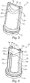
- the support struts 20 form with the base 14, a frame part 12, in which a cup-shaped or pocket-shaped filter element 30 is received and held. How out Fig. 2 it can be seen, the support strut 20 along the inside and the outside of the filter element 30 is arranged.
- welded marginal edges of the filter element 30 can be enclosed or enclosed on both sides by a support strut 20.
- a fluid may flow through the socket 14 into an internal cavity of the filter 10 and then through the filter element 30.
- a flow from the outside to the inside can take place.
- the filter element 30 is formed from a thin filter material 31, in particular a filter fabric.
- the filter element 30 has a sleeve-shaped peripheral region 34.
- a foot portion 32 of the filter element 30 is open and incorporated in the annular base 14.
- the filter element 30 is closed.
- the filter element 30 with the peripheral region 34 and the head region 36 is formed from a single piece of filter material 31 by folding and welding two longitudinal marginal edges. The welded edges are shown in the illustration Fig. 1 obscured by the beam-like support struts 20.
- the head region 36 of the filter element 30 has a saddle shape with a curved edge 42.
- two lateral tips 38 are formed on two opposite convex portions.
- two troughs 39 are arranged in an adjacent concave area of the edge 42.
- Between the two equal-height tips 38 extends transversely to a longitudinal axis of the filter 10 and also transversely to the connecting line between the two tips 38 a groove-shaped groove 40.
- the bottom of the groove-shaped groove 40 passes through the two low points 39, which are arranged at the same level.
- the saddle-shaped head portion 36 has the special shape of a relatively large filter surface with a high dimensional stability. Due to the high dimensional stability, it is sufficient in the embodiment shown that the thin-walled filter element 30 is held exclusively by a substantially linear connection with the inner and outer support struts 20.
- the support struts 20 each have at their upper free end a radially inwardly projecting cap 22, in each of which a tip 38 is at least partially received and held.
- the filter element 30 can be glued into the frame part 12 or preferably connected directly to the frame part 12 during injection molding.
- FIG Fig. 3 Another embodiment of a filter 10 according to the invention is shown in FIG Fig. 3 shown, wherein the filter 10 is constructed substantially as the filter 10 of Fig. 1 , In contrast to the filter 10 according to Fig. 1 shows the second embodiment Fig. 2 on the head portion 36 an additional cross member 24.
- the bar-shaped transverse strut 24 extends between the two distal ends of the two support struts 20.
- the filter material 31 of the filter element 30 is connected in the head region 36 with the corresponding contoured underside of the transverse strut 24.
- the cross member 24 serves as an additional stiffening and support of the filter surface on the head portion 36th
- the third embodiment of a filter 10 according to the invention Fig. 4 is based on the described first embodiment according to Fig. 1 ,
- the frame part 12 has a second pair of support struts 20b, wherein the two pairs are arranged offset by 90 ° to each other.
- the support struts 20a of the first pair extend in accordance with the embodiment Fig. 4
- the support struts 20b of the second pair extend from the socket 14 along the peripheral portion 34 of the filter element 30 to the troughs 39 of the groove 40 on the saddle-shaped head portion 36.
- the head portion 36 is thus supported and held at the maxima and minima of the edge region 42 by the vertical support struts 20a, 20b with their respective radially inwardly projecting cover caps 22.
- a welded edge 34 indicated at the edge 42 of the head portion 36 which further extends along the struts 20a at the peripheral portion 34 of the sleeve-shaped filter portion 30 to the base 14.
- a fourth embodiment of a filter 10 according to the invention is shown.
- the fourth embodiment largely corresponds to the third embodiment according to Fig. 4 , wherein the two pairs of support struts 20a, 20b respectively at the head portion 36 have a transverse strut 24a, 24b.
- the two transverse struts 24a, 24b intersect in the region of the longitudinal axis of the filter 10 at a right angle.
- the two transverse struts 24a, 24b are formed as relatively thin beams, which follow in their direction of extension of the saddle shape of the head portion 36 and conform to the respective contour.
- a fifth embodiment of a filter 10 according to the invention which has a frame member 12 with two support struts 20.
- This fifth embodiment is similar to the embodiment according to FIG Fig. 1 wherein in the filter 10 according to the fifth embodiment, the filter element 30 is conical.
- the filter element 30 tapers from the base 14 to the head region 36.
- the frame part 12 is formed with two transverse struts 20, which extend inclined towards the center and are adapted to the conical outer contour of the peripheral region 34 of the filter element 30.
- the embodiments according to the FIGS. 1 to 5 can also be conical, while the embodiment according to Fig. 6 can also be cylindrical.
Landscapes
- Chemical & Material Sciences (AREA)
- Chemical Kinetics & Catalysis (AREA)
- Engineering & Computer Science (AREA)
- Textile Engineering (AREA)
- Filtering Of Dispersed Particles In Gases (AREA)
- Filtering Materials (AREA)
- Filtration Of Liquid (AREA)
Description
- Die Erfindung betrifft einen Filter zum Filter einer Flüssigkeit oder eines Gases mit einem taschenförmigen Filterelement, welches einen hülsenförmigen Umfangsbereich, einen geschlossenen Kopfbereich und einen offenen Fußbereich aufweist, und einem Rahmenelement, welches einen ringförmigen Sockel, in welchem der Fußbereich des Filterelementes aufgenommen ist, und mindestens eine Stützstrebe aufweist, welche sich von dem Sockel weg entlang des Umfangsbereiches des Filterelementes erstreckt, gemäß dem Oberbegriff des Anspruchs 1.
- Derartige hülsenförmige oder kerzenartige Filter werden vielfältig eingesetzt, insbesondere in Fluidleitungen, um etwa Feststoffpartikel rückzuhalten. Bei diesen Filtern ist es gewünscht, dass diese einerseits sehr kompakt sind, um diese auch in kleinen Leitungen anzuordnen. Andererseits sollen diese eine große wirksame Filterfläche aufweisen, so dass ein hinreichender Fluiddurchsatz bei einem möglichst geringen Strömungswiderstand gegeben ist.
- Aus der
EP 1 088 720 A2 geht ein Filter für eine Scheibenreinigungsanlage eines Kraftfahrzeuges mit einem Sockel und einem zylindrischen Filterelement hervor, welches über Stützstreben am Sockel gehaltert ist. An dem vom Sockel abgewandten Kopfbereich des Filterelementes ist ein scheibenförmiges Einlegeteil vorgesehen, welches über einen ringförmigen Halteabschnitt mit den Stützstreben verbunden ist. - Aus der
DE 20 2011 109 523 U1 ist ein Filter zum Einsetzen in einen Einfüllstutzen eines Behälters bekannt. Dieser Filter weist ebenfalls ein Rahmenteil mit einem Sockel und in Längsrichtung verlaufenden Stützstreben auf, welche ein hülsenförmiges Filterelement halten. An dem dem Sockel abgewandten Auslaufende ist ein Filtersieb angeordnet, welches zur Strömungsrichtung geneigt ist. - Die Ausbildung des Filterelementes aus mehreren Teilen ist grundsätzlich arbeits- und kostenaufwändig. Zudem besteht ein Problem von möglichen Undichtigkeiten.
- Aus der
EP 2 165 749 B1 geht ein Filter mit einem Rahmenelement und einem Filterelement hervor. Das Filterelement ist als ein einfacher durchgehender Streifen ausgebildet, welcher sich an dem kerzenförmigen Filter entlang von zwei relativ breiten seitlichen Stützstreben erstreckt. Im Gegensatz zu einem taschen- oder beutelförmigen Filterelement ergibt sich bei diesem bekannten Filter aufgrund der relativ breiten seitlichen Stützstreben eine begrenzte Filterfläche. - Ein solcher Filter mit einem Rahmenelement mit zwei Stützstreben und einem ringförmigen Sockel, welcher auch als Rohrstutzen bezeichnet werden kann, geht auch aus der
DE 20 2008 012 284 U1 hervor. - Ein in eine Kaffeetasse einhängbarer Filterbeutel, auch drip-bag genannt, ist aus
EP 1 419 720 A1 bekannt. Dieser Filterbeutel weist an seinen gegenüberliegenden Seitenflächen faltbare Blechhaken auf. - Ein gattungsgemäßer Filter ist aus der
DE 100 52 166 A1 bekannt. Das Filterelement ist dabei taschenförmig mit einem hülsenartigen Umfangsbereich ausgebildet, dessen Kopfbereich geschlossen und dessen Fußbereich offen ist. Der Fußbereich ist von einem ringförmigen Sockel oder Rohrstutzen zum Einbau in eine Ölleitung umschlossen. Das hülsenförmige Filterelement und der rohrstutzenartige Sockel bilden einen kerzenförmigen Filter. Das Filterelement ist dabei so konfektioniert, dass der geschlossene Kopfbereich entweder konvex, kuppelartig ausgebildet oder nach innen eingestülpt geformt ist. Bei einer Einstülpung nach innen erstrecken sich die seitlichen Stützstreben in die konkave Einstülpung hinein, um diese Filterform zu stabilisieren. Durch diese Stützstreben werden der Raum in der Einstülpung und die Filterfläche in nicht unerheblichem Maße eingeschränkt. - Der Erfindung liegt die Aufgabe zugrunde, einen Filter anzugeben, welcher bei einer guten Herstellbarkeit einen kompakten Aufbau und eine große Filterfläche ermöglicht.
- Die Aufgabe wird nach der Erfindung durch einen Filter mit den Merkmalen des Anspruchs 1 gelöst. Bevorzugte Ausführungsformen der Erfindung sind in den abhängigen Ansprüchen angegeben.
- Der erfindungsgemäße Filter ist dadurch gekennzeichnet, dass der Kopfbereich des Filterelementes sattelförmig ausgebildet ist, wobei zwei seitliche Spitzen vorgesehen sind, zwischen denen eine rinnenförmige Auskehlung ausgebildet ist.
- Der erfindungsgemäße Filter weist ein taschen- oder beutelförmiges Filterelement auf, welches einfach herzustellen ist und eine große Filterfläche ermöglicht. Der offene Fußbereich des hülsenförmigen Filterelementes ist an dem ringförmigen Sockel angebracht, welcher insbesondere zum Einbau in eine Fluidleitung oder in eine Behälteröffnung ausgebildet ist. Der ringförmige Sockel mit der mindestens einen Stützstrebe des Rahmenelementes sorgt für eine Formstabilisierung des hülsenförmigen Umfangsbereiches des Filterelementes. Der vom Sockel abgewandte Kopfbereich des Filterelementes ist gemäß der Erfindung sattelförmig ausgebildet. Die Sattelform umfasst dabei zwei seitliche Spitzen, zwischen denen sich eine rinnenförmige Auskehlung erstreckt. Durch diese Sattelform wird eine relativ große Filterfläche auch im Kopfbereich des Filterelementes geschaffen, wobei gleichzeitig eine hohe Formstabilität gewährleistet ist. Insbesondere der teilweise konkav und teilweise konvex verlaufende Rand am Übergang des sattelförmigen Kopfbereiches am hülsenförmigen Umfangsbereich führt zu einer guten Festigkeit auch bei wechselnden Strömungen.
- Grundsätzlich kann das taschenförmige Filterelement als ein einstückiger Formkörper gebildet, etwa tiefgezogen oder aus mehreren Teilstücken aufgebaut sein. Eine besonders vorteilhafte Ausführungsform der Erfindung besteht jedoch darin, dass das taschenförmige Filterelement aus einem einzelnen flächigen Filtermaterial durch Falten und Verschweißen von Randkanten gebildet ist. Auf diese Weise kann das taschenförmige Filterelement einfach und kostengünstig hergestellt werden. Das Materialstück kann effizient aus einem flächigen Ausgangsmaterial zugeschnitten werden.
- Grundsätzlich sind verschiedene Falt- und Verschweißungsvarianten möglich. So können etwa zwei zu verschweißende Randkanten so angeordnet sein, dass diese etwa L-förmig verlaufen, wobei eine Randkante im Kopfbereich des Filterelementes und die andere Randkante entlang des Umfangsbereiches des Filterelementes verlaufen würde.
- Eine besonders zweckmäßige Ausführungsvariante der Erfindung liegt darin, dass zwei verschweißte Randkanten vorgesehen sind, welche entlang einer Längsachse des Filterelementes verlaufen und sich von dem Fußbereich zu dem Kopfbereich des taschenförmigen Filterelementes erstrecken. Hierdurch werden die verschweißten Randkanten in den weniger belasteten Umfangsbereich des Filterelementes verlegt. Die verschweißten Randkanten können dabei durch die axial verlaufenden Stützstreben abgedeckt und zusätzlich stabilisiert werden.
- Eine weitere bevorzugte Ausführungsvariante der Erfindung besteht darin, dass mindestens zwei Stützstreben paarweise vorgesehen sind, welche sich entlang von gegenüberliegenden Seiten des taschenförmigen Filterelementes erstrecken. Die Stützstreben sind dabei zumindest bereichsweise mit dem Filterelement verbunden, so dass sie die Form des insgesamt hülsen- oder kerzenförmigen Filterelementes stabilisieren. Eine gegenüberliegende und damit symmetrische Anordnung der zwei Stützstreben erlaubt eine symmetrische und damit gleichmäßige Belastung des Filters bei anliegender Strömung. Diese ist üblicherweise in Längsrichtung des Filters gerichtet.
- Eine besonders stabile Ausbildung eines Filters wird gemäß einer weiteren Ausführungsform der Erfindung dadurch erreicht, dass die mindestens eine Stützstrebe sich entlang mindestens einer verschweißten Randkante des Filterelementes von dem Sockel bis zu einer der Spitzen im Kopfbereich erstreckt und dass die verschweißte Randkante durch die Stützstrebe abgedeckt ist. Damit wird den Stützstreben eine doppelte Funktion zugewiesen. Diese stabilisieren zum einen die Hülsenform des Filterelementes und schützen zum anderen die verschweißten Randkanten des Filterelementes. Hierdurch wird auch die Gefahr einer Undichtigkeit entlang der Randkanten herabgesetzt. Vorzugsweise können die Spitzen des Filterelementes von Abdeckkappen aufgenommen und abgedeckt sein, welche einstückig am oberen Ende der Stützstreben ausgebildet sind.
- Eine weitere Verbesserung der Festigkeit und Stabilität des Filters wird gemäß einer bevorzugten Ausführungsform der Erfindung dadurch erzielt, dass an dem Kopfbereich die zwei Stützstreben eines Paares durch mindestens eine Querstrebe miteinander verbunden sind. Vorzugsweise ist die Querstrebe im Kopfbereich ebenfalls mit dem Filterelement zumindest bereichsweise verbunden, so dass die Querstrebe die Formgebung im Kopfbereich unterstützt und stabilisiert.
- Dabei ist es nach einer weiteren Ausführungsform der Erfindung besonders vorteilhaft, dass die mindestens eine Querstrebe an die Sattelform des Kopfbereiches angepasst ist. Vorzugsweise kann dabei die Querstrebe über ihre gesamte Länge fest mit dem Filtermaterial des Filtermateriales im Kopfbereich verbunden sein. Bei einer Falt- und Verschweißungsvariante, bei welcher eine verschweißte Randkante im Kopfbereich verläuft, ist diese vorzugsweise durch eine Querstrebe abgedeckt.
- Eine weitere Festigkeitserhöhung kann gemäß einer Ausführungsvariante der Erfindung dadurch erreicht werden, dass zwei Paare von Stützstreben angeordnet sind, welche um 90° versetzt zueinander am Umfang des Sockels angeordnet sind. Vorzugsweise können dabei die beiden Paare jeweils eine Querstrebe aufweisen, welche im Kopfbereich kreuzweise angeordnet sind. Vorzugsweise erstreckt sich dabei eine erste Querstrebe zwischen den beiden Spitzen im Kopfbereich, während sich die zweite Querstrebe rechtwinklig hierzu entlang der Rinnenachse der rinnenförmigen Auskehlung erstreckt. Hierdurch wird eine besonders stabile Form des Filterelementes erreicht.
- Grundsätzlich können die Stütz- und Querstreben entlang nur der Innenseite oder der Außenseite des Filterelementes angeordnet sein. Bevorzugt ist es nach einer Ausführungsform der Erfindung, dass mindestens eine Stützstrebe und/oder mindestens eine Querstrebe an der Innenseite und der Außenseite des taschenförmigen Filterelementes angeordnet und mit dieser verbunden sind. Vorzugsweise sind alle Stütz- und Querstreben entlang der Innen- und Außenseite vorgesehen. Grundsätzlich ist es aber auch möglich, einen Teil der Streben an der Außenseite und einen Teil an der Innenseite des Filterelementes anzuordnen.
- Grundsätzlich kann der erfindungsgemäße Filter in beliebiger Weise hergestellt werden. Eine besonders wirtschaftliche Herstellung ist gemäß einer Ausführung der Erfindung dadurch erreichbar, dass das Rahmenelement aus einem Kunststoffmaterial durch Gießen, insbesondere Spritzgießen, hergestellt ist, wobei das Filterelement beim Gießen mit dem Rahmenelement fest verbunden ist. Insbesondere wird das taschenförmige Filterelement in eine Gussform eingesetzt, so dass dieses beim Einschießen des aufgeschmolzenen Kunststoffmateriales unmittelbar fest mit dem Rahmenelement verbunden wird.
- Zur Herstellung des Filterelementes können unterschiedliche Materialien eingesetzt werden. Besonders vorteilhaft ist es, dass das Filterelement ein Gewebe, ein Vlies, ein Gewirk und/oder eine Membran aufweist. Insbesondere kann das Filterelement aus einem flächigen Filtermaterial gebildet sein, welches auch aus einer Kombination der vorgenannten Materialien aufgebaut ist.
- Weiterhin wird eine besonders kompakte Formgebung mit einer großen Filterfläche gemäß einer Ausführungsvariante der Erfindung dadurch erzielt, dass der Umfangsbereich des Filterelementes zylindrisch oder konisch ausgebildet ist.
- Die Erfindung wird nachfolgend anhand von bevorzugten Ausführungsbeispielen weiter beschrieben, welche schematisch in den beigefügten Zeichnungen dargestellt sind. In den Zeichnungen zeigen:
- Fig. 1
- eine perspektivische Ansicht eines ersten erfindungsgemäßen Filters mit zwei Stützstreben;
- Fig. 2
- eine perspektivische Ansicht des ersten erfindungsgemäßen Filters von
Fig. 1 von unten; - Fig. 3
- eine perspektivische Ansicht eines zweiten erfindungsgemäßen Filters mit einer Querstrebe;
- Fig. 4
- eine perspektivische Ansicht eines dritten erfindungsgemäßen Filters mit vier Stützstreben;
- Fig. 5
- eine perspektivische Ansicht eines vierten erfindungsgemäßen Filters mit zwei Querstreben; und
- Fig. 6
- eine perspektivische Ansicht eines fünften erfindungsgemäßen Filter mit konischem Filterelement.
- Gemäß einem ersten Ausführungsbeispiel gemäß den
Figuren 1 und 2 ist ein erfindungsgemäßer Filter 10 kerzenförmig mit einem rohrstutzenartigen Sockel 14 ausgebildet. Der ringförmige Sockel 14 ist an seiner Außenseite mit einem Dichtring 16 versehen, so dass der Filter 10 mit dem Sockel 14 in eine Leitung eingebaut werden kann. An dem Sockel 14 sind zwei gegenüberliegende, sich im Wesentlichen parallel zur Längsachse des Filters 10 erstreckende Stützstreben 20 angeordnet. Die Stützstreben 20 bilden mit dem Sockel 14 ein Rahmenteil 12, in welchem ein becherförmiges oder taschenförmiges Filterelement 30 aufgenommen und gehalten ist. Wie ausFig. 2 zu ersehen ist, wird die Stützstrebe 20 entlang der Innenseite und der Außenseite des Filterelements 30 angeordnet. Somit können verschweißte Randkanten des Filterelements 30 beidseitig von einer Stützstrebe 20 eingeschlossen oder umschlossen sein. Ein Fluid kann durch den Sockel 14 in einen inneren Hohlraum des Filters 10 und dann durch das Filterelement 30 strömen. Alternativ kann auch eine Durchströmung von außen nach innen erfolgen. - Das Filterelement 30 ist aus einem dünnen Filtermaterial 31, insbesondere einem Filtergewebe gebildet. Das Filterelement 30 weist einen hülsenförmigen Umfangsbereich 34 auf. Ein Fußbereich 32 des Filterelementes 30 ist offen und in dem ringförmigen Sockel 14 eingebunden. An einem dem Sockel 14 gegenüberliegenden Kopfbereich 36 ist das Filterelement 30 geschlossen. Das Filterelement 30 mit dem Umfangsbereich 34 und dem Kopfbereich 36 ist aus einem einzelnen Stück Filtermaterial 31 durch Falten und Verschweißen von zwei längs verlaufenden Randkanten gebildet. Die verschweißten Randkanten sind in der Darstellung gemäß
Fig. 1 von den balkenartigen Stützstreben 20 verdeckt. - Der Kopfbereich 36 des Filterelementes 30 weist erfindungsgemäß eine Sattelform mit einem geschwungenen Rand 42 auf. Entlang des geschwungenen Randes 42 sind an zwei gegenüberliegenden konvexen Abschnitten zwei seitliche Spitzen 38 ausgebildet. In einem angrenzenden konkaven Bereich des Randes 42 sind zwei Tiefpunkte 39 angeordnet. Zwischen den beiden gleichhohen Spitzen 38 erstreckt sich quer zu einer Längsachse des Filters 10 und auch quer zur Verbindungslinie zwischen den beiden Spitzen 38 eine rinnenförmige Auskehlung 40. Der Grund der rinnenförmigen Auskehlung 40 läuft durch die beiden Tiefpunkte 39, welche niveaugleich angeordnet sind.
- Der sattelförmige Kopfbereich 36 weist durch die spezielle Formgebung eine relativ große Filterfläche bei einer hohen Formstabilität auf. Aufgrund der hohen Formstabilität ist es bei der gezeigten Ausführungsform ausreichend, dass das dünnwandige Filterelement 30 ausschließlich durch eine im Wesentlichen linienförmige Verbindung mit den innen- und außenliegenden Stützstreben 20 gehalten ist. Die Stützstreben 20 weisen jeweils an ihrem oberen freien Ende eine radial nach innen ragende Abdeckkappe 22 auf, in welchen jeweils eine Spitze 38 zumindest teilweise aufgenommen und gehalten ist.
- Das Filterelement 30 kann in das Rahmenteil 12 eingeklebt oder vorzugsweise unmittelbar beim Spritzgießen mit dem Rahmenteil 12 verbunden sein.
- Eine weitere Ausführungsform eines erfindungsgemäßen Filters 10 ist in
Fig. 3 dargestellt, wobei der Filter 10 im Wesentlichen so aufgebaut ist, wie der Filter 10 vonFig. 1 . Im Unterschied zum Filter 10 gemäßFig. 1 weist die zweite Ausführungsform nachFig. 2 am Kopfbereich 36 eine zusätzliche Querstrebe 24 auf. Die balkenförmige Querstrebe 24 erstreckt sich zwischen den beiden distalen Enden der zwei Stützstreben 20. Das Filtermaterial 31 des Filterelementes 30 ist im Kopfbereich 36 mit der entsprechen konturierten Unterseite der Querstrebe 24 verbunden. Auf diese Weise dient die Querstrebe 24 als eine zusätzliche Versteifung und Halterung der Filterfläche am Kopfbereich 36. - Die dritte Ausführungsform eines erfindungsgemäßen Filters 10 gemäß
Fig. 4 basiert auf der beschriebenen ersten Ausführungsform gemäßFig. 1 . Zusätzlich zu der ersten Ausführungsform mit einem ersten Paar von Stützstreben 20a weist das Rahmenteil 12 ein zweites Paar von Stützstreben 20b auf, wobei die beiden Paare um 90° zueinander versetzt angeordnet sind. - Wie bei der ersten Ausführungsform gemäß
Fig. 1 erstrecken sich die Stützstreben 20a des ersten Paares bei der Ausführungsform gemäßFig. 4 linear entlang des Umfangsbereiches 34 des Filterelementes 30 bis zu den Spitzen 38 am Kopfbereich 36. Die Stützstreben 20b des zweiten Paares erstrecken sich vom Sockel 14 längs des Umfangsbereiches 34 des Filterelementes 30 bis zu den Tiefpunkten 39 der Auskehlung 40 am sattelförmigen Kopfbereich 36. Der Kopfbereich 36 wird so an den Maxima und Minima des Randbereiches 42 durch die vertikalen Stützstreben 20a, 20b mit ihren jeweiligen, radial nach innen ragenden Abdeckkappen 22 gestützt und gehalten. Zudem ist inFig. 4 noch am Rand 42 des Kopfbereiches 36 eine verschweißte Randkante 34 angedeutet, welche sich weiter entlang der Streben 20a am Umfangsbereich 34 des hülsenförmigen Filterbereiches 30 bis zum Sockel 14 erstreckt. - In
Fig. 5 ist eine vierte Ausführungsform eines erfindungsgemäßen Filters 10 dargestellt. Die vierte Ausführungsform entspricht weitgehend der dritten Ausführungsform gemäßFig. 4 , wobei die zwei Paare von Stützstreben 20a, 20b jeweils am Kopfbereich 36 eine Querstrebe 24a, 24b aufweisen. Die beiden Querstreben 24a, 24b kreuzen sich im Bereich der Längsachse des Filters 10 in einem rechten Winkel. Die beiden Querstreben 24a, 24b sind als relativ dünne Balken ausgebildet, welche in ihrer Erstreckungsrichtung der Sattelform des Kopfbereiches 36 folgen und sich an die jeweilige Kontur anschmiegen. - Gemäß
Fig. 6 ist eine fünfte Ausführungsform eines erfindungsgemäßen Filters 10 dargestellt, welcher ein Rahmenelement 12 mit zwei Stützstreben 20 aufweist. Diese fünfte Ausführungsform ähnelt der Ausführungsform gemäßFig. 1 , wobei bei dem Filter 10 gemäß der fünften Ausführungsform das Filterelement 30 konisch ausgebildet ist. Dabei verjüngt sich das Filterelement 30 vom Sockel 14 her zum Kopfbereich 36. Entsprechend ist das Rahmenteil 12 mit zwei Querstreben 20 ausgebildet, welche zur Mitte hin geneigt verlaufen und so an die konische Außenkontur des Umfangsbereiches 34 des Filterelementes 30 angepasst sind. Die Ausführungsformen gemäß denFiguren 1 bis 5 können auch konisch ausgebildet sein, während die Ausführungsform gemäßFig. 6 auch zylindrisch sein kann.
Claims (12)
- Filter zum Filtern einer Flüssigkeit oder eines Gases mit- einem taschenförmigen Filterelement (30), welches einen hülsenförmigen Umfangsbereich (34), einen geschlossenen Kopfbereich (36) und einen offenen Fußbereich (32) aufweist, und- einem Rahmenelement (12), welches einen ringförmigen rohrstutzenartigen Sockel (14), in welchem der Fußbereich (32) des Filterelementes (30) aufgenommen ist, und mindestens eine Stützstrebe (20) aufweist, welche sich von dem Sockel (14) weg entlang des Umfangsbereiches (34) des Filterelementes (30) erstreckt,dadurch gekennzeichnet,
dass der vom Sockel (14) abgewandte Kopfbereich (36) des Filterelementes (30) sattelförmig ausgebildet ist, wobei zwei seitliche Spitzen (38) vorgesehen sind, zwischen denen eine rinnenförmige Auskehlung (40) ausgebildet ist. - Filter nach Anspruch 1,
dadurch gekennzeichnet,
dass das taschenförmige Filterelement (30) aus einem einzelnen flächigen Filtermaterial (31) durch Falten und Verschweißen von Randkanten (33) gebildet ist. - Filter nach Anspruch 2,
dadurch gekennzeichnet,
dass zwei verschweißte Randkanten (33) vorgesehen sind, welche entlang einer Längsachse des Filterelementes (30) verlaufen und sich von dem Fußbereich (32) zu dem Kopfbereich (36) des taschenförmigen Filterelementes (30) erstrecken. - Filter nach einem der Ansprüche 1 bis 3,
dadurch gekennzeichnet,
dass die mindestens eine Stützstrebe (20) sich entlang mindestens einer verschweißten Randkante (33) des Filterelementes (30) von dem Sockel (14) bis zu einer der Spitzen (38) im Kopfbereich (36) erstreckt und
dass die verschweißte Randkante (33) durch die Stützstrebe (20) abgedeckt sind. - Filter nach einem der Ansprüche 1 bis 4,
dadurch gekennzeichnet,
dass mindestens zwei Stützstreben (20) paarweise vorgesehen sind, welche sich entlang von gegenüberliegenden Seiten des taschenförmigen Filterelementes (30) erstrecken. - Filter nach Anspruch 5,
dadurch gekennzeichnet,
dass an dem Kopfbereich (36) die zwei Stützstreben (20) eines Paares durch mindestens eine Querstrebe (24) miteinander verbunden sind. - Filter nach Anspruch 5 oder 6,
dadurch gekennzeichnet,
dass zwei Paare von Stützstreben (20) angeordnet sind, welche um 90° versetzt zueinander am Umfang des Sockels (14) angeordnet sind. - Filter nach Anspruch 6 oder 7,
dadurch gekennzeichnet,
dass die mindestens eine Querstrebe (24) an die Sattelform des Kopfbereiches (36) angepasst ist. - Filter nach einem der Ansprüche 1 bis 8,
dadurch gekennzeichnet,
dass mindestens eine Stützstrebe (20) und/oder mindestens eine Querstrebe (24) an der Innenseite und der Außenseite des taschenförmigen Filterelementes (30) angeordnet und mit dieser verbunden ist. - Filter nach einem der Ansprüche 1 bis 9,
dadurch gekennzeichnet,
dass das Rahmenelement (12) aus einem Kunststoffmaterial durch Gießen, insbesondere Spritzgießen, hergestellt ist, wobei das Filterelement (30) beim Gießen mit dem Rahmenelement (12) fest verbunden ist. - Filter nach einem der Ansprüche 1 bis 10,
dadurch gekennzeichnet,
dass das Filterelement (30) ein Gewebe, ein Vlies, ein Gewirk und/oder eine Membran aufweist. - Filter nach einem der Ansprüche 1 bis 11,
dadurch gekennzeichnet,
dass der Umfangsbereich (34) des Filterelementes (30) zylindrisch oder konisch ausgebildet ist.
Priority Applications (7)
| Application Number | Priority Date | Filing Date | Title |
|---|---|---|---|
| ES15152464.2T ES2632793T3 (es) | 2015-01-26 | 2015-01-26 | Filtro para filtrar un líquido o un gas |
| PL15152464T PL3047890T3 (pl) | 2015-01-26 | 2015-01-26 | Filtr do filtrowania cieczy lub gazu |
| EP15152464.2A EP3047890B1 (de) | 2015-01-26 | 2015-01-26 | Filter zum Filtern einer Flüssigkeit oder eines Gases |
| JP2017539337A JP2018508347A (ja) | 2015-01-26 | 2015-10-29 | 液体または気体を濾過するためのフィルタ |
| US15/535,209 US10315145B2 (en) | 2015-01-26 | 2015-10-29 | Filter for filtering a liquid or a gas |
| CN201580074626.XA CN107206296B (zh) | 2015-01-26 | 2015-10-29 | 用于过滤液体或气体的过滤器 |
| PCT/EP2015/075093 WO2016119926A1 (de) | 2015-01-26 | 2015-10-29 | Filter zum filtern einer flüssigkeit oder eines gases |
Applications Claiming Priority (1)
| Application Number | Priority Date | Filing Date | Title |
|---|---|---|---|
| EP15152464.2A EP3047890B1 (de) | 2015-01-26 | 2015-01-26 | Filter zum Filtern einer Flüssigkeit oder eines Gases |
Publications (2)
| Publication Number | Publication Date |
|---|---|
| EP3047890A1 EP3047890A1 (de) | 2016-07-27 |
| EP3047890B1 true EP3047890B1 (de) | 2017-04-19 |
Family
ID=52391876
Family Applications (1)
| Application Number | Title | Priority Date | Filing Date |
|---|---|---|---|
| EP15152464.2A Active EP3047890B1 (de) | 2015-01-26 | 2015-01-26 | Filter zum Filtern einer Flüssigkeit oder eines Gases |
Country Status (7)
| Country | Link |
|---|---|
| US (1) | US10315145B2 (de) |
| EP (1) | EP3047890B1 (de) |
| JP (1) | JP2018508347A (de) |
| CN (1) | CN107206296B (de) |
| ES (1) | ES2632793T3 (de) |
| PL (1) | PL3047890T3 (de) |
| WO (1) | WO2016119926A1 (de) |
Families Citing this family (3)
| Publication number | Priority date | Publication date | Assignee | Title |
|---|---|---|---|---|
| CN109821306A (zh) * | 2019-03-20 | 2019-05-31 | 镇江东亚碳素焦化有限公司 | 一种煅烧焦炭的除尘装置及其除尘方法 |
| CN115069029B (zh) * | 2022-06-27 | 2025-05-13 | 无锡亿利环保科技有限公司 | 滤纸筒结构、圆筒形空气滤芯及滤芯制作工艺 |
| EP4647140A1 (de) * | 2024-05-08 | 2025-11-12 | MANN+HUMMEL GmbH | Filtersystem zum filtern von fluiden und filterelement für ein filtersystem |
Family Cites Families (9)
| Publication number | Priority date | Publication date | Assignee | Title |
|---|---|---|---|---|
| JPS5160512U (de) * | 1974-11-08 | 1976-05-13 | ||
| DE8526820U1 (de) * | 1985-09-19 | 1989-01-12 | Gebrüder Holder GmbH & Co, 7430 Metzingen | Pflanzenschutzmittel-Tank |
| DE19946551A1 (de) | 1999-09-29 | 2001-04-05 | Mannesmann Vdo Ag | Zur Montage strömungsseitig vor einer Pumpe einer Scheibenreinigungsanlage eines Kraftfahrzeuges vorgesehener Filter |
| JP2001120920A (ja) | 1999-10-21 | 2001-05-08 | Gp Daikyo Corp | オイルストレーナ |
| ATE454071T1 (de) * | 2001-07-30 | 2010-01-15 | Ohki Co Ltd | Filterbeutel |
| DE202008012284U1 (de) | 2008-09-15 | 2008-12-24 | Karl Küfner KG | Filter für flüssige und gasförmige Medien |
| US20110132817A1 (en) * | 2009-12-03 | 2011-06-09 | Eric Rankin Gardner | Systems and methods associated with straining a pipeline |
| JP2011148312A (ja) * | 2011-02-09 | 2011-08-04 | Nifco Inc | メッシュ、そのメッシュを用いたフィルタとそのフィルタの製造方法 |
| DE202011109523U1 (de) | 2011-12-21 | 2013-03-25 | Reutter Gmbh | Filter zum Einsetzen in einen Einfüllstutzen eines Behälters |
-
2015
- 2015-01-26 PL PL15152464T patent/PL3047890T3/pl unknown
- 2015-01-26 EP EP15152464.2A patent/EP3047890B1/de active Active
- 2015-01-26 ES ES15152464.2T patent/ES2632793T3/es active Active
- 2015-10-29 JP JP2017539337A patent/JP2018508347A/ja not_active Ceased
- 2015-10-29 US US15/535,209 patent/US10315145B2/en not_active Expired - Fee Related
- 2015-10-29 CN CN201580074626.XA patent/CN107206296B/zh active Active
- 2015-10-29 WO PCT/EP2015/075093 patent/WO2016119926A1/de not_active Ceased
Non-Patent Citations (1)
| Title |
|---|
| None * |
Also Published As
| Publication number | Publication date |
|---|---|
| CN107206296B (zh) | 2019-12-24 |
| ES2632793T3 (es) | 2017-09-15 |
| JP2018508347A (ja) | 2018-03-29 |
| PL3047890T3 (pl) | 2017-08-31 |
| EP3047890A1 (de) | 2016-07-27 |
| WO2016119926A1 (de) | 2016-08-04 |
| CN107206296A (zh) | 2017-09-26 |
| US20170354909A1 (en) | 2017-12-14 |
| US10315145B2 (en) | 2019-06-11 |
Similar Documents
| Publication | Publication Date | Title |
|---|---|---|
| EP3525913B1 (de) | Rundfilterelement, insbesondere zur gasfiltration | |
| DE102014016908B4 (de) | Filterelement mit Filterbalg, Filtersystem und Verwendung des Filtersystems | |
| EP3452205B1 (de) | Filterelement, insbesondere zur gasfiltration, und filtereinrichtung | |
| EP2481460B2 (de) | Filterelement eines Flüssigkeitsfilters und Flüssigkeitsfilter | |
| EP2676713B1 (de) | Gasfiltereinsatz | |
| DE102014009887A1 (de) | Filterelement, Filter mit einem Filterelement und Filtergehäuse eines Filters | |
| WO2013045285A1 (de) | Filterelement | |
| DE102014007373B4 (de) | Faltenförmiges Filterelement | |
| EP2845636B1 (de) | Filterelement und Verfahren zur Herstellung eines Filterelements | |
| WO2015055584A1 (de) | Filterelement, insbesondere zur gasfiltration | |
| WO2016119926A1 (de) | Filter zum filtern einer flüssigkeit oder eines gases | |
| EP2125157B1 (de) | Fluidfilter mit einem in ein filtergehäuse einsetzbaren filterelement | |
| DE102014010260A1 (de) | Luftfiltervorrichtung,insbesondere für ein Kraftfahrzeug | |
| DE202011002684U1 (de) | Filter zum Einsetzen in den Einfüllstutzen eines Behälters | |
| DE102008008328B4 (de) | Luftfiltereinsatz mit Verstärkungsring | |
| EP4098346B1 (de) | Filtervorrichtung | |
| EP3297745B1 (de) | Filterelement, insbesondere zur gasfiltration | |
| DE102009048588A1 (de) | Filtereinrichtung, insbesondere zur Flüssigkeitsfilterung in Brennkraftmaschinen | |
| EP3452201B1 (de) | Filtereinrichtung, insbesondere gasfilter | |
| DE20102217U1 (de) | Filter für Flüssigkeiten, insbesondere Kraftstoffe | |
| DE102012012349B4 (de) | Gas-Filtereinsatz, Verfahren zu dessen Herstellung und Luftfilter für eine Brennkraftmaschine | |
| WO2017190871A1 (de) | Ringförmiges filterelement, insbesondere zur gasfiltration, und filtereinrichtung | |
| DE10216349C1 (de) | Gehäuse für eine Airbageinrichtung mit Gehäuseversteifungen | |
| DE102013004284A1 (de) | Filtereinrichtung und Filterelement für eine Filtereinrichtung | |
| EP4426468B1 (de) | Rundfilterelement zur filtration eines gasförmigen fluids |
Legal Events
| Date | Code | Title | Description |
|---|---|---|---|
| PUAI | Public reference made under article 153(3) epc to a published international application that has entered the european phase |
Free format text: ORIGINAL CODE: 0009012 |
|
| 17P | Request for examination filed |
Effective date: 20150923 |
|
| AK | Designated contracting states |
Kind code of ref document: A1 Designated state(s): AL AT BE BG CH CY CZ DE DK EE ES FI FR GB GR HR HU IE IS IT LI LT LU LV MC MK MT NL NO PL PT RO RS SE SI SK SM TR |
|
| AX | Request for extension of the european patent |
Extension state: BA ME |
|
| GRAP | Despatch of communication of intention to grant a patent |
Free format text: ORIGINAL CODE: EPIDOSNIGR1 |
|
| INTG | Intention to grant announced |
Effective date: 20170104 |
|
| GRAS | Grant fee paid |
Free format text: ORIGINAL CODE: EPIDOSNIGR3 |
|
| GRAA | (expected) grant |
Free format text: ORIGINAL CODE: 0009210 |
|
| AK | Designated contracting states |
Kind code of ref document: B1 Designated state(s): AL AT BE BG CH CY CZ DE DK EE ES FI FR GB GR HR HU IE IS IT LI LT LU LV MC MK MT NL NO PL PT RO RS SE SI SK SM TR |
|
| REG | Reference to a national code |
Ref country code: GB Ref legal event code: FG4D Free format text: NOT ENGLISH |
|
| REG | Reference to a national code |
Ref country code: CH Ref legal event code: EP |
|
| REG | Reference to a national code |
Ref country code: AT Ref legal event code: REF Ref document number: 885397 Country of ref document: AT Kind code of ref document: T Effective date: 20170515 Ref country code: CH Ref legal event code: NV Representative=s name: SCHMAUDER AND PARTNER AG PATENT- UND MARKENANW, CH |
|
| REG | Reference to a national code |
Ref country code: IE Ref legal event code: FG4D Free format text: LANGUAGE OF EP DOCUMENT: GERMAN |
|
| REG | Reference to a national code |
Ref country code: DE Ref legal event code: R096 Ref document number: 502015000874 Country of ref document: DE |
|
| REG | Reference to a national code |
Ref country code: NL Ref legal event code: MP Effective date: 20170419 |
|
| REG | Reference to a national code |
Ref country code: LT Ref legal event code: MG4D |
|
| REG | Reference to a national code |
Ref country code: ES Ref legal event code: FG2A Ref document number: 2632793 Country of ref document: ES Kind code of ref document: T3 Effective date: 20170915 |
|
| PG25 | Lapsed in a contracting state [announced via postgrant information from national office to epo] |
Ref country code: NL Free format text: LAPSE BECAUSE OF FAILURE TO SUBMIT A TRANSLATION OF THE DESCRIPTION OR TO PAY THE FEE WITHIN THE PRESCRIBED TIME-LIMIT Effective date: 20170419 |
|
| PG25 | Lapsed in a contracting state [announced via postgrant information from national office to epo] |
Ref country code: HR Free format text: LAPSE BECAUSE OF FAILURE TO SUBMIT A TRANSLATION OF THE DESCRIPTION OR TO PAY THE FEE WITHIN THE PRESCRIBED TIME-LIMIT Effective date: 20170419 Ref country code: FI Free format text: LAPSE BECAUSE OF FAILURE TO SUBMIT A TRANSLATION OF THE DESCRIPTION OR TO PAY THE FEE WITHIN THE PRESCRIBED TIME-LIMIT Effective date: 20170419 Ref country code: LT Free format text: LAPSE BECAUSE OF FAILURE TO SUBMIT A TRANSLATION OF THE DESCRIPTION OR TO PAY THE FEE WITHIN THE PRESCRIBED TIME-LIMIT Effective date: 20170419 Ref country code: NO Free format text: LAPSE BECAUSE OF FAILURE TO SUBMIT A TRANSLATION OF THE DESCRIPTION OR TO PAY THE FEE WITHIN THE PRESCRIBED TIME-LIMIT Effective date: 20170719 Ref country code: GR Free format text: LAPSE BECAUSE OF FAILURE TO SUBMIT A TRANSLATION OF THE DESCRIPTION OR TO PAY THE FEE WITHIN THE PRESCRIBED TIME-LIMIT Effective date: 20170720 |
|
| PG25 | Lapsed in a contracting state [announced via postgrant information from national office to epo] |
Ref country code: BG Free format text: LAPSE BECAUSE OF FAILURE TO SUBMIT A TRANSLATION OF THE DESCRIPTION OR TO PAY THE FEE WITHIN THE PRESCRIBED TIME-LIMIT Effective date: 20170719 Ref country code: RS Free format text: LAPSE BECAUSE OF FAILURE TO SUBMIT A TRANSLATION OF THE DESCRIPTION OR TO PAY THE FEE WITHIN THE PRESCRIBED TIME-LIMIT Effective date: 20170419 Ref country code: IS Free format text: LAPSE BECAUSE OF FAILURE TO SUBMIT A TRANSLATION OF THE DESCRIPTION OR TO PAY THE FEE WITHIN THE PRESCRIBED TIME-LIMIT Effective date: 20170819 Ref country code: SE Free format text: LAPSE BECAUSE OF FAILURE TO SUBMIT A TRANSLATION OF THE DESCRIPTION OR TO PAY THE FEE WITHIN THE PRESCRIBED TIME-LIMIT Effective date: 20170419 Ref country code: LV Free format text: LAPSE BECAUSE OF FAILURE TO SUBMIT A TRANSLATION OF THE DESCRIPTION OR TO PAY THE FEE WITHIN THE PRESCRIBED TIME-LIMIT Effective date: 20170419 |
|
| REG | Reference to a national code |
Ref country code: DE Ref legal event code: R097 Ref document number: 502015000874 Country of ref document: DE |
|
| REG | Reference to a national code |
Ref country code: FR Ref legal event code: PLFP Year of fee payment: 4 |
|
| PG25 | Lapsed in a contracting state [announced via postgrant information from national office to epo] |
Ref country code: RO Free format text: LAPSE BECAUSE OF FAILURE TO SUBMIT A TRANSLATION OF THE DESCRIPTION OR TO PAY THE FEE WITHIN THE PRESCRIBED TIME-LIMIT Effective date: 20170419 Ref country code: EE Free format text: LAPSE BECAUSE OF FAILURE TO SUBMIT A TRANSLATION OF THE DESCRIPTION OR TO PAY THE FEE WITHIN THE PRESCRIBED TIME-LIMIT Effective date: 20170419 Ref country code: DK Free format text: LAPSE BECAUSE OF FAILURE TO SUBMIT A TRANSLATION OF THE DESCRIPTION OR TO PAY THE FEE WITHIN THE PRESCRIBED TIME-LIMIT Effective date: 20170419 |
|
| PLBE | No opposition filed within time limit |
Free format text: ORIGINAL CODE: 0009261 |
|
| STAA | Information on the status of an ep patent application or granted ep patent |
Free format text: STATUS: NO OPPOSITION FILED WITHIN TIME LIMIT |
|
| PG25 | Lapsed in a contracting state [announced via postgrant information from national office to epo] |
Ref country code: SM Free format text: LAPSE BECAUSE OF FAILURE TO SUBMIT A TRANSLATION OF THE DESCRIPTION OR TO PAY THE FEE WITHIN THE PRESCRIBED TIME-LIMIT Effective date: 20170419 |
|
| REG | Reference to a national code |
Ref country code: DE Ref legal event code: R082 Ref document number: 502015000874 Country of ref document: DE Representative=s name: WUNDERLICH & HEIM PATENTANWAELTE PARTNERSCHAFT, DE |
|
| 26N | No opposition filed |
Effective date: 20180122 |
|
| PG25 | Lapsed in a contracting state [announced via postgrant information from national office to epo] |
Ref country code: MT Free format text: LAPSE BECAUSE OF FAILURE TO SUBMIT A TRANSLATION OF THE DESCRIPTION OR TO PAY THE FEE WITHIN THE PRESCRIBED TIME-LIMIT Effective date: 20170419 |
|
| PG25 | Lapsed in a contracting state [announced via postgrant information from national office to epo] |
Ref country code: LU Free format text: LAPSE BECAUSE OF NON-PAYMENT OF DUE FEES Effective date: 20180126 |
|
| REG | Reference to a national code |
Ref country code: IE Ref legal event code: MM4A |
|
| REG | Reference to a national code |
Ref country code: BE Ref legal event code: MM Effective date: 20180131 |
|
| PG25 | Lapsed in a contracting state [announced via postgrant information from national office to epo] |
Ref country code: BE Free format text: LAPSE BECAUSE OF NON-PAYMENT OF DUE FEES Effective date: 20180131 |
|
| PG25 | Lapsed in a contracting state [announced via postgrant information from national office to epo] |
Ref country code: IE Free format text: LAPSE BECAUSE OF NON-PAYMENT OF DUE FEES Effective date: 20180126 |
|
| PGFP | Annual fee paid to national office [announced via postgrant information from national office to epo] |
Ref country code: RO Payment date: 20190328 Year of fee payment: 6 |
|
| PG25 | Lapsed in a contracting state [announced via postgrant information from national office to epo] |
Ref country code: MC Free format text: LAPSE BECAUSE OF FAILURE TO SUBMIT A TRANSLATION OF THE DESCRIPTION OR TO PAY THE FEE WITHIN THE PRESCRIBED TIME-LIMIT Effective date: 20170419 |
|
| PG25 | Lapsed in a contracting state [announced via postgrant information from national office to epo] |
Ref country code: TR Free format text: LAPSE BECAUSE OF FAILURE TO SUBMIT A TRANSLATION OF THE DESCRIPTION OR TO PAY THE FEE WITHIN THE PRESCRIBED TIME-LIMIT Effective date: 20170419 |
|
| PG25 | Lapsed in a contracting state [announced via postgrant information from national office to epo] |
Ref country code: PT Free format text: LAPSE BECAUSE OF FAILURE TO SUBMIT A TRANSLATION OF THE DESCRIPTION OR TO PAY THE FEE WITHIN THE PRESCRIBED TIME-LIMIT Effective date: 20170419 |
|
| PG25 | Lapsed in a contracting state [announced via postgrant information from national office to epo] |
Ref country code: MK Free format text: LAPSE BECAUSE OF NON-PAYMENT OF DUE FEES Effective date: 20170419 Ref country code: CY Free format text: LAPSE BECAUSE OF FAILURE TO SUBMIT A TRANSLATION OF THE DESCRIPTION OR TO PAY THE FEE WITHIN THE PRESCRIBED TIME-LIMIT Effective date: 20170419 Ref country code: HU Free format text: LAPSE BECAUSE OF FAILURE TO SUBMIT A TRANSLATION OF THE DESCRIPTION OR TO PAY THE FEE WITHIN THE PRESCRIBED TIME-LIMIT; INVALID AB INITIO Effective date: 20150126 |
|
| PG25 | Lapsed in a contracting state [announced via postgrant information from national office to epo] |
Ref country code: AL Free format text: LAPSE BECAUSE OF FAILURE TO SUBMIT A TRANSLATION OF THE DESCRIPTION OR TO PAY THE FEE WITHIN THE PRESCRIBED TIME-LIMIT Effective date: 20170419 |
|
| REG | Reference to a national code |
Ref country code: CH Ref legal event code: PL |
|
| PG25 | Lapsed in a contracting state [announced via postgrant information from national office to epo] |
Ref country code: SI Free format text: LAPSE BECAUSE OF NON-PAYMENT OF DUE FEES Effective date: 20180126 Ref country code: LI Free format text: LAPSE BECAUSE OF NON-PAYMENT OF DUE FEES Effective date: 20200131 Ref country code: CH Free format text: LAPSE BECAUSE OF NON-PAYMENT OF DUE FEES Effective date: 20200131 |
|
| REG | Reference to a national code |
Ref country code: AT Ref legal event code: MM01 Ref document number: 885397 Country of ref document: AT Kind code of ref document: T Effective date: 20200126 |
|
| PG25 | Lapsed in a contracting state [announced via postgrant information from national office to epo] |
Ref country code: AT Free format text: LAPSE BECAUSE OF NON-PAYMENT OF DUE FEES Effective date: 20200126 |
|
| P01 | Opt-out of the competence of the unified patent court (upc) registered |
Effective date: 20230505 |
|
| PGFP | Annual fee paid to national office [announced via postgrant information from national office to epo] |
Ref country code: DE Payment date: 20250122 Year of fee payment: 11 |
|
| PGFP | Annual fee paid to national office [announced via postgrant information from national office to epo] |
Ref country code: ES Payment date: 20250214 Year of fee payment: 11 |
|
| PGFP | Annual fee paid to national office [announced via postgrant information from national office to epo] |
Ref country code: FR Payment date: 20250123 Year of fee payment: 11 Ref country code: CZ Payment date: 20250110 Year of fee payment: 11 Ref country code: PL Payment date: 20250114 Year of fee payment: 11 |
|
| PGFP | Annual fee paid to national office [announced via postgrant information from national office to epo] |
Ref country code: IT Payment date: 20250131 Year of fee payment: 11 Ref country code: SK Payment date: 20250116 Year of fee payment: 11 Ref country code: GB Payment date: 20250123 Year of fee payment: 11 |