EP3047540B1 - Clamping cage for an edge connector - Google Patents
Clamping cage for an edge connector Download PDFInfo
- Publication number
- EP3047540B1 EP3047540B1 EP14766684.6A EP14766684A EP3047540B1 EP 3047540 B1 EP3047540 B1 EP 3047540B1 EP 14766684 A EP14766684 A EP 14766684A EP 3047540 B1 EP3047540 B1 EP 3047540B1
- Authority
- EP
- European Patent Office
- Prior art keywords
- busbar
- terminal
- cage
- terminal cage
- connection module
- Prior art date
- Legal status (The legal status is an assumption and is not a legal conclusion. Google has not performed a legal analysis and makes no representation as to the accuracy of the status listed.)
- Active
Links
- 239000004020 conductor Substances 0.000 claims description 42
- 238000004519 manufacturing process Methods 0.000 claims description 22
- IHQKEDIOMGYHEB-UHFFFAOYSA-M sodium dimethylarsinate Chemical class [Na+].C[As](C)([O-])=O IHQKEDIOMGYHEB-UHFFFAOYSA-M 0.000 claims description 9
- 238000003466 welding Methods 0.000 claims description 8
- 238000003825 pressing Methods 0.000 claims description 2
- 238000003780 insertion Methods 0.000 description 17
- 230000037431 insertion Effects 0.000 description 17
- 239000000463 material Substances 0.000 description 11
- RYGMFSIKBFXOCR-UHFFFAOYSA-N Copper Chemical compound [Cu] RYGMFSIKBFXOCR-UHFFFAOYSA-N 0.000 description 4
- 239000010949 copper Substances 0.000 description 4
- 229910052802 copper Inorganic materials 0.000 description 4
- 238000000034 method Methods 0.000 description 3
- 239000002699 waste material Substances 0.000 description 3
- 239000011810 insulating material Substances 0.000 description 2
- 229910000881 Cu alloy Inorganic materials 0.000 description 1
- 229910000639 Spring steel Inorganic materials 0.000 description 1
- 230000001154 acute effect Effects 0.000 description 1
- 230000001419 dependent effect Effects 0.000 description 1
- 239000012777 electrically insulating material Substances 0.000 description 1
- 210000003746 feather Anatomy 0.000 description 1
- 239000002184 metal Substances 0.000 description 1
- 229910052751 metal Inorganic materials 0.000 description 1
- 238000002360 preparation method Methods 0.000 description 1
- 238000004080 punching Methods 0.000 description 1
Images


Classifications
-
- H—ELECTRICITY
- H01—ELECTRIC ELEMENTS
- H01R—ELECTRICALLY-CONDUCTIVE CONNECTIONS; STRUCTURAL ASSOCIATIONS OF A PLURALITY OF MUTUALLY-INSULATED ELECTRICAL CONNECTING ELEMENTS; COUPLING DEVICES; CURRENT COLLECTORS
- H01R4/00—Electrically-conductive connections between two or more conductive members in direct contact, i.e. touching one another; Means for effecting or maintaining such contact; Electrically-conductive connections having two or more spaced connecting locations for conductors and using contact members penetrating insulation
- H01R4/28—Clamped connections, spring connections
- H01R4/48—Clamped connections, spring connections utilising a spring, clip, or other resilient member
- H01R4/4809—Clamped connections, spring connections utilising a spring, clip, or other resilient member using a leaf spring to bias the conductor toward the busbar
- H01R4/48185—Clamped connections, spring connections utilising a spring, clip, or other resilient member using a leaf spring to bias the conductor toward the busbar adapted for axial insertion of a wire end
-
- H—ELECTRICITY
- H01—ELECTRIC ELEMENTS
- H01R—ELECTRICALLY-CONDUCTIVE CONNECTIONS; STRUCTURAL ASSOCIATIONS OF A PLURALITY OF MUTUALLY-INSULATED ELECTRICAL CONNECTING ELEMENTS; COUPLING DEVICES; CURRENT COLLECTORS
- H01R4/00—Electrically-conductive connections between two or more conductive members in direct contact, i.e. touching one another; Means for effecting or maintaining such contact; Electrically-conductive connections having two or more spaced connecting locations for conductors and using contact members penetrating insulation
- H01R4/28—Clamped connections, spring connections
- H01R4/48—Clamped connections, spring connections utilising a spring, clip, or other resilient member
- H01R4/4809—Clamped connections, spring connections utilising a spring, clip, or other resilient member using a leaf spring to bias the conductor toward the busbar
- H01R4/4828—Spring-activating arrangements mounted on or integrally formed with the spring housing
- H01R4/48365—Spring-activating arrangements mounted on or integrally formed with the spring housing with integral release means
-
- H—ELECTRICITY
- H01—ELECTRIC ELEMENTS
- H01R—ELECTRICALLY-CONDUCTIVE CONNECTIONS; STRUCTURAL ASSOCIATIONS OF A PLURALITY OF MUTUALLY-INSULATED ELECTRICAL CONNECTING ELEMENTS; COUPLING DEVICES; CURRENT COLLECTORS
- H01R4/00—Electrically-conductive connections between two or more conductive members in direct contact, i.e. touching one another; Means for effecting or maintaining such contact; Electrically-conductive connections having two or more spaced connecting locations for conductors and using contact members penetrating insulation
- H01R4/28—Clamped connections, spring connections
- H01R4/48—Clamped connections, spring connections utilising a spring, clip, or other resilient member
- H01R4/4809—Clamped connections, spring connections utilising a spring, clip, or other resilient member using a leaf spring to bias the conductor toward the busbar
- H01R4/48455—Clamped connections, spring connections utilising a spring, clip, or other resilient member using a leaf spring to bias the conductor toward the busbar insertion of a wire only possible by pressing on the spring
-
- H—ELECTRICITY
- H01—ELECTRIC ELEMENTS
- H01R—ELECTRICALLY-CONDUCTIVE CONNECTIONS; STRUCTURAL ASSOCIATIONS OF A PLURALITY OF MUTUALLY-INSULATED ELECTRICAL CONNECTING ELEMENTS; COUPLING DEVICES; CURRENT COLLECTORS
- H01R43/00—Apparatus or processes specially adapted for manufacturing, assembling, maintaining, or repairing of line connectors or current collectors or for joining electric conductors
- H01R43/16—Apparatus or processes specially adapted for manufacturing, assembling, maintaining, or repairing of line connectors or current collectors or for joining electric conductors for manufacturing contact members, e.g. by punching and by bending
-
- H—ELECTRICITY
- H01—ELECTRIC ELEMENTS
- H01R—ELECTRICALLY-CONDUCTIVE CONNECTIONS; STRUCTURAL ASSOCIATIONS OF A PLURALITY OF MUTUALLY-INSULATED ELECTRICAL CONNECTING ELEMENTS; COUPLING DEVICES; CURRENT COLLECTORS
- H01R4/00—Electrically-conductive connections between two or more conductive members in direct contact, i.e. touching one another; Means for effecting or maintaining such contact; Electrically-conductive connections having two or more spaced connecting locations for conductors and using contact members penetrating insulation
- H01R4/28—Clamped connections, spring connections
- H01R4/48—Clamped connections, spring connections utilising a spring, clip, or other resilient member
-
- H—ELECTRICITY
- H01—ELECTRIC ELEMENTS
- H01R—ELECTRICALLY-CONDUCTIVE CONNECTIONS; STRUCTURAL ASSOCIATIONS OF A PLURALITY OF MUTUALLY-INSULATED ELECTRICAL CONNECTING ELEMENTS; COUPLING DEVICES; CURRENT COLLECTORS
- H01R9/00—Structural associations of a plurality of mutually-insulated electrical connecting elements, e.g. terminal strips or terminal blocks; Terminals or binding posts mounted upon a base or in a case; Bases therefor
- H01R9/22—Bases, e.g. strip, block, panel
- H01R9/24—Terminal blocks
- H01R9/26—Clip-on terminal blocks for side-by-side rail- or strip-mounting
Definitions
- the present invention relates to a connection module for an electrical direct plug-in terminal according to the preamble of claim 1, as well as the direct plug-in terminal.
- connection module For connecting electrical conductors to an electrical assembly connection devices are often used in which the stripped end of the electrical conductor is pressed or pulled by a spring or a spring-loaded pressure piece against a busbar. In this case, the busbar is connected to the electrical assembly or connectable.
- connection devices are usually manufactured in modular design and then have a clamping cage, in which there is the terminal point at which the spring or the pressure piece pushes or pulls the conductor end to the busbar.
- connection modules For the production of such connection modules a variety of designs is known. The designs differ for example by the materials used for the clamping cage, the spring and the busbar.
- clamping cage and spring are made in one piece from a material having good spring characteristics, for example, a spring steel, and the bus bar is made separately from a highly conductive material, such as copper. Or these components are all made separately, with the clamping cage optionally a very inexpensive, preferably thin-walled material is used.
- Such connection devices with separately manufactured busbar shows, for example, the document DE 20 2011 000 714 U1 , Generic devices show the DE 102 53 858 A1 and DE 10 2010 010262 A1 , It is also known, busbar and clamping cage, and possibly also the spring to manufacture in one piece. In these connection modules of the clamping cage but is relatively expensive and requires much material due to large waste. In addition, good conductive material such as copper is expensive.
- the one-piece production of busbar and terminal cage requires a large distance between a plurality of successively arranged connection modules.
- the object of the invention is therefore to provide a connection module in which the clamping cage, although made of a highly conductive material, in particular a copper-containing metal or copper, but still inexpensive can be produced, as well as a direct plug-in terminal with the connection module, a series connection device with a plurality of connection modules and a method for producing the connection module.
- connection module having the features of claim 1, a direct plug-in terminal having the features of claim 9, a series connection device having the features of claim 12 and a method having the features of claim 13. Further advantageous embodiments can be found in the dependent claims.
- a connection module for an electrical connection device for connecting an electrical conductor to an electrical assembly which comprises a clamping cage and a busbar.
- the clamping cage is provided for providing a terminal point for the electrical conductor.
- the clamping cage and the busbar are each made in one piece from a well electrically conductive flat ribbon.
- a copper alloy is preferably used for the flat strips.
- the flat strips, from which the clamping cage and the busbar are made, each have two opposite broad sides and these connecting narrow sides.
- the clamping cage and the busbar are intended for the conduction of an electric current.
- clamping cage and / or the busbar are produced as stamped parts or as stamped and bent parts.
- the narrow sides of the flat band of the busbar form such narrow sides of the busbar, and the narrow sides of the flat band of the clamping cage thus form narrow sides of the clamping cage.
- the thickness of the busbar and the clamping cage is dimensioned so that both the busbar and the clamping cage have sufficient mechanical stability and sufficient current carrying capacity.
- the clamping cage has at least three walls arranged at an angle to each other, which extend parallel or substantially parallel to a conductor insertion direction.
- substantially parallel includes a clamping cage in which at least one of the walls is arranged at an acute angle to the conductor insertion direction, in particular at an angle of 0 ° -60 °.
- all walls of the clamping cage parallel to the conductor insertion extend.
- the walls are preferably arranged at a right angle to each other.
- connection module is characterized in that the clamping cage is permanently attached to a narrow side of the busbar cohesively.
- connection module Compared to a one-piece production of the clamping cage with busbar falls in this configuration of the connection module hardly any waste, so that the waste content and thus the material consumption in the production can be significantly reduced.
- the production of this connection module requires an additional process step in which clamping cage and busbar are permanently attached to each other, the production of the connection module due to the saving of high-quality flat strip material is still considerably cheaper possible.
- the narrow sides of the flat band for the clamping cage, the narrow sides of the clamping cage, and since the narrow sides of the flat strip for the busbar are the narrow sides of the busbar, the narrow sides of the clamping cage, the thickness of the flat strip used for the clamping cage, and the narrow sides of the busbar have the Thickness of the narrow sides of the ribbon used for the busbar on.
- the clamping cage is U-shaped. It is preferred that two of the walls are narrow walls which are interconnected by the third wall, which is referred to below as the connecting wall. Preferably, one of the narrow walls is provided for supporting a spring. Further preferably, a clamping point for the electrical conductor is provided between the second narrow wall and the spring. In a likewise preferred embodiment, the clamping cage is square in cross section. In this embodiment, it is preferably circumferentially closed, or preferably also designed to be circumferentially open.
- the clamping cage In the embodiment in which the clamping cage is U-shaped, it encloses the nip to a large extent. In the embodiment in which the clamping cage is quadrangular in cross-section, it encloses the clamping point almost completely or even completely.
- clamping cage and the busbar are fastened to one another at a line-shaped connecting seam.
- they are cohesively interconnected, most preferably by welding, in particular by resistance welding or by laser welding.
- the clamping cage preferably has a longitudinal extent. It is preferred that it at least partially surrounds an interior in a circumferential direction to the longitudinal extent.
- the clamping point for clamping the electrical conductor is arranged on the clamping cage or on the busbar in the interior.
- the clamping cage is also open on two opposite end faces, which are arranged transversely to the longitudinal extent. It is preferred that the bus bar is arranged on one of the front sides and in particular parallel to it. The interior of the clamping cage remains accessible in this embodiment, at least from the opposite end side.
- the clamping cage has a first wall which is extended relative to at least one further wall of the clamping cage, so that this wall has an extension.
- the extension is preferably formed as a rectangular tongue.
- the extension is extended relative to at least one upper edge, a lower edge or a side edge of a wall of the clamping cage. It is the busbar attached to the extension of the clamping cage.
- the busbar with respect to the upper edge, the lower edge or the side edge is spaced and placed very flexible application specific in the connection module.
- the object is further achieved with a direct plug-in terminal comprising such a connection module.
- the direct plug-in terminal is preferably a spring-loaded terminal which has a spring.
- the spring is preferably at least partially disposed in the interior of the clamping cage and provided to press an electrical conductor against the busbar or to pull the busbar.
- the direct plug-in terminal comprises an insulating material housing.
- the insulating material surrounds the clamping cage preferably fully.
- a conductor insertion opening is provided in the insulating housing, through which an electrical conductor in the clamping cage, in particular in the nip, can be inserted.
- the object is further achieved with a series connection device with at least two such connection modules.
- the series connection device is characterized in that the connection modules have a common busbar and a distance between adjacent terminal cages of the connection modules smaller as a width of one of the clamping cages, in particular a narrow side of the clamping cage, is.
- the clamping cages of the inventive series connection device can be produced independently of their width, in particular the width of their narrow walls. Therefore, they are closer to each other.
- a distance between adjacent clamping cages of the series terminal device according to the invention is less than 0.7 times the width of a narrow wall of one of the clamping cages, more preferably less than 0.5 times the width of the narrow wall.
- connection module The object is also achieved with a method for producing such a connection module, according to the subject matter of claim 13.
- the fastening is preferably effected by material bonding by welding, preferably by resistance or laser welding.
- connection module using high-quality materials due to the considerable material savings compared to a one-piece production of the connection module is significantly cheaper possible.
- FIG. 1 shows a connection device 10 with a connection module 1 according to the invention.
- the connection device 10 is designed as a direct plug-in terminal (Push In).
- connection module 1 For this purpose, it has a housing 12, which is made of an electrically insulating material, with a housing interior 13, in which the connection module 1 is arranged.
- the connection module 1 comprises a clamping cage 2 and a busbar 3, which are manufactured independently of each other and then attached to each other inseparably.
- the connection device 10 has a spring 4 which extends into an inner space 24 of the clamping cage 2. The interior 24 of the clamping cage 2 is accessible through a conductor insertion opening 11.
- the clamping cage extends in a longitudinal direction 60 here opposite to the conductor insertion direction 80.
- the busbar 3 is arranged in this embodiment on the clamping cage 2, that it extends transversely to the conductor insertion direction 11.
- the spring 4 is here approximately V-shaped and has two spring legs 41, 42. It is mounted about a housing pin 14 so that a conductor insertion opening 11 facing the first spring leg 41 in and against a pivoting direction 141 about the housing pin 14 is pivotable. With the second, the conductor insertion opening 11 facing away from the spring leg 42, the spring 4 is supported upon pivoting of the first spring leg 41 on the clamping cage 2.
- a pressure piece 5 is provided, which is manually, in particular with a tool (not shown), operable.
- the first spring leg 41 is actuated by pressing the pressure piece 5 in a Portereinfuelcardi 80 so that a clamping point (not shown), which is arranged in the interior 24 of the clamping cage 2, opens.
- an electrical conductor 8 is inserted into the nip.
- the clamping cage 2 is therefore provided here for providing the nip.
- the electrical conductor 8 is in the Fig. 1 shown schematically. He has a stripped wire end 81, with which he can be inserted into the nip.
- connection module 1 for such a connection device 10 is shown.
- the spring 4 and the pressure piece 5 are shown in the position relative to the connection module 1, in which they are arranged in the connection device 10.
- Fig. 1 (c) shows the flat strip 300, from which the busbar 3 is made. It has two opposite broad sides 320, which are interconnected by narrow sides 310.
- the flat strip 300 extends in a unwinding direction 330, wherein the narrow sides 310 extend transversely and longitudinally to the unwinding direction 330.
- the flat strip 300 has a constant thickness D3, which corresponds to a height H3 of the narrow sides 310.
- a busbar 3 for the connection module 1 of Fig. 1 (b) manufacture the flat strip 300 is here only cut to length.
- the busbar 3 is therefore preferably made here as a stamped part.
- the narrow sides 310 of the flat strip 300 are therefore the narrow sides 31 of the busbar 3.
- the clamping cage 2 is produced from a flat strip 200 unwound in the unwinding direction 230.
- the shape of the broad sides 220 for example, by punching or sawing, adjusted.
- the ribbon 200 is bent to the clamping cage 2.
- the clamping cage 2 is therefore produced as a stamped and bent part.
- the narrow sides 210 of the thus adapted and bent flat belt 200 are the narrow sides 21 of the clamping cage 2. They have a height H2, which corresponds to the thickness D2 of the flat belt 200.
- the settlement of the clamping cage 2 shows the Fig. 1 (d) ,
- the clamping cage 2 of Fig. 1 (b) . (E) is square in cross section. It therefore has four walls 221-223, three of which are shown here.
- the walls 221-223 are disposed at an approximately right angle (not labeled) to each other. They each have an extension component 601 in the longitudinal extension direction 60 and an extension component 602 transversely to the longitudinal extension direction 60 of the clamping cage 2.
- the longitudinal extension direction 60 extends counter to the conductor insertion direction 80.
- the walls 221-223 are therefore provided parallel to the conductor insertion direction 80.
- the clamping cage 2 has two mutually opposite walls 222, 223, which have a width Bw, here a width Bs of the busbar 3 plus the height H2 of the narrow sides 21 of the clamping cage 2 corresponds.
- these opposing walls 222, 223 are referred to as narrow walls.
- the spring 4 is supported.
- the nip is disposed between the spring 4 and a second of the two narrow walls 222.
- the narrow walls 222, 223 are interconnected by a connecting wall 221.
- the connecting wall 221 has a greater width Bv determined by the spring and a clamping angle 41 of the spring 4 than the narrow walls 222, 223.
- a first wall 221 of the clamping cage 2 is extended relative to its other walls 222, 223, so that this wall 221 has an extension 27 formed as a rectangular tongue.
- extension 27 and tongue are used synonymously below. The tongue 27 therefore extends beyond a lower edge 281 of the clamping cage 2 seen in the conductor insertion direction 80.
- the busbar 3 is attached to the extension 27 on the clamping cage 2. Namely, it is attached with one of its narrow sides 31 on the extension 27 on the clamping cage 2. It is flush with an edge 271 of the extension 27 is provided. As a result, it is spaced from the lower edge 281. The distance A is in the Fig. 1 (e) shown.
- the attachment is preferably cohesive, preferably by welding.
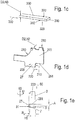
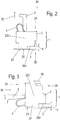
- FIGS. 2 and 3 show two further embodiments - not according to the invention - connection modules 1.
- the busbar 3 is arranged on a narrow side 21 of the clamping cage 2.
- the busbar 3 extends the Fig. 2 transverse to the longitudinal extension direction 60 of the clamping cage 2, that is parallel to the end faces 25, 26 of the clamping cage 2, and in the Fig. 3 in the longitudinal extension direction 60, that is transversely to the end faces 25, 26 of the clamping cage 2.
- the clamping cage 2 of the Fig. 2 accessible from one of the end faces 25 from the outside, the clamping cage 2 of the Fig. 3 from both end faces 25, 26.
- the first wall 221 is elongated.
- the first wall 221 extended so that it protrudes in the conductor insertion direction 80 with respect to a lower edge 281 of a wall 222, 223 of the clamping cage 2 protrudes.
- the busbar 3 is provided flush with an edge 271 of the extension 27. Therefore, in this embodiment, it is spaced from the lower edge 281 by the distance A.
- the first wall 221 is extended so that, viewed in the conductor insertion direction 80, it projects beyond a side edge 282 of the clamping cage 2.
- the busbar 3 is therefore spaced in this embodiment from the side edge 282 by the distance A.
- connection modules 1 produced in this way have the advantage over previously known connection modules (not shown) that a considerable material saving of approximately 15% -25% is possible during their production.
- the Fig. 4 shows in (a) - (d) respectively a series terminal device 100 with at least two such connection modules 1 each without a housing 12.
- the connection modules 1 each have a common busbar 3, and at least two or more clamping cages 2.
- the clamping cage 2 is welded in each case to the narrow side 31 of the busbar 3.
- the clamping cage 2 is connected at its tongue 27 to the busbar 3.
- connection modules 1 are provided.
- the clamping cages 2 of the two connection modules 1 are arranged on the common busbar 3.
- the busbar 3 has a bend 32 between the clamping cages 2, so that the conductor insertion directions 80 of an electrical conductor are arranged in the clamping cages 2 in an angle determined by the bend 32 (not designated) relative to one another.
- the two clamping cages 2 are here also arranged in mirror symmetry to an axis of symmetry 9. As a result, they are oriented opposite each other. Your Portereintechnologyö réelleen 11 are therefore arranged on the side facing away from its adjacent clamping cage 2 side.
- connection modules 1 oriented in the same direction are arranged with the smallest possible distance A1 between them.
- the series connection device 100 has two such groups of connection modules 1, wherein the connection modules 1 of the two groups are arranged mirror-symmetrically to the mirror axis 9.
- the clamping cages 2 of the two groups are therefore oriented opposite to each other.
- the series connection arrangement 100 makes possible independently of each other manufacturing the busbar 3 and the clamping cages 2 a very close placement of the clamping cages 2 on the busbar 3 side by side.
- the distance A1 between adjacent 2 clamping cages can therefore be chosen very small. It is smaller than the sum of the widths B of the narrow walls 223, 222 of the adjacent clamping cages 2 selectable.
- connection modules 1 In the series terminal device 100 of Fig. 4 (c) are arranged oriented in the same direction connection modules 1 with the smallest possible distance A1 to each other.
- the distance A1 is smaller than the sum of the widths B of the narrow walls 2222, 223 of the adjacent clamping cages 2.
- the series terminal device 100 has a facing in the opposite direction connection module 1, which is further spaced from the four grouped connection modules 1.
- the series terminal device 100 of Fig. 4 (d) has two to the mirror axis 9 mirror-symmetrically arranged connection modules 1, which are arranged widely spaced from each other.
- FIG. 5 shows in (a) the series terminal device 100 of Fig. 4 (c) , and in (b) the series terminal devices 100 of Fig. 4 (b) , each with housing 12. Both series terminal devices 100 have locking feet 101, with which they on a Support rail (not shown) can be arranged. As a result, a plurality of such row connection devices 100 can be arranged next to each other on the same support rail in a row.
Description
Die vorliegende Erfindung betrifft ein Anschlussmodul für eine elektrische Direktsteckklemme nach dem Oberbegriff des Anspruchs 1, sowie die Direktsteckklemme.The present invention relates to a connection module for an electrical direct plug-in terminal according to the preamble of
Des weiteren wird in dem Anspruch 13 ein Verfahren zur Herstellung eines Anschlussmoduls gemäß Anspruch 1 angegeben. Zum Anschluss elektrischer Leiter an eine elektrische Baugruppe werden häufig Anschlussvorrichtungen verwendet, bei denen das abisolierte Ende des elektrischen Leiters mittels einer Feder oder einem federbehafteten Druckstück gegen eine Stromschiene gedrückt oder gezogen wird. Dabei ist die Stromschiene mit der elektrischen Baugruppe verbunden oder verbindbar.Furthermore, a method for producing a connection module according to
Solche Anschlussvorrichtungen werden zumeist in Modulbauweise hergestellt und weisen dann einen Klemmkäfig auf, in dem sich die Klemmstelle befindet, an der die Feder oder das Druckstück das Leiterende an die Stromschiene drückt oder zieht.Such connection devices are usually manufactured in modular design and then have a clamping cage, in which there is the terminal point at which the spring or the pressure piece pushes or pulls the conductor end to the busbar.
Für die Herstellung solcher Anschlussmodule ist eine Vielzahl von Ausführungen bekannt. Die Ausführungen unterscheiden sich beispielsweise durch die verwendeten Materialien für den Klemmkäfig, die Feder und die Stromschiene.For the production of such connection modules a variety of designs is known. The designs differ for example by the materials used for the clamping cage, the spring and the busbar.
Häufig werden Klemmkäfig und Feder aus einem Material mit guten Federeigenschaften einstückig hergestellt, beispielsweise aus einem Federstahl, und die Stromschiene wird separat aus einem gut leitenden Material hergestellt, beispielsweise aus Kupfer. Oder diese Bauelemente werden alle separat hergestellt, wobei für den Klemmkäfig gegebenenfalls ein sehr kostengünstiges, vorzugsweise dünnwandiges, Material verwendbar ist. Solche Anschlussvorrichtungen mit separat gefertigter Stromschiene zeigt beispielsweise die Druckschrift
Die Aufgabe der Erfindung ist es daher, ein Anschlussmodul bereit zu stellen, bei dem der Klemmkäfig zwar aus einem gut leitfähigen Material, insbesondere aus einem kupferhaltigen Metall oder aus Kupfer, gefertigt, aber trotzdem kostengünstig herstellbar ist, sowie eine Direktsteckklemme mit dem Anschlussmodul, eine Reihenanschlussvorrichtung mit mehreren Anschlussmodulen und ein Verfahren zur Herstellung des Anschlussmoduls.The object of the invention is therefore to provide a connection module in which the clamping cage, although made of a highly conductive material, in particular a copper-containing metal or copper, but still inexpensive can be produced, as well as a direct plug-in terminal with the connection module, a series connection device with a plurality of connection modules and a method for producing the connection module.
Diese Aufgabe wird durch ein Anschlussmodul mit den Merkmalen des Anspruchs 1, eine Direktsteckklemme mit den Merkmalen des Anspruchs 9, einer Reihenanschlussvorrichtung mit den Merkmalen des Anspruchs 12 sowie ein Verfahren mit den Merkmalen des Anspruchs 13 gelöst. Weitere vorteilhafte Ausführungsformen sind den abhängigen Ansprüchen zu entnehmen.This object is achieved by a connection module having the features of
Dafür wird ein Anschlussmodul für eine elektrische Anschlussvorrichtung zum Verbinden eines elektrischen Leiters mit einer elektrischen Baugruppe geschaffen, welches einen Klemmkäfig sowie eine Stromschiene umfasst. Der Klemmkäfig ist zur Bereitstellung einer Klemmstelle für den elektrischen Leiter vorgesehen. Der Klemmkäfig und die Stromschiene sind unabhängig voneinander jeweils einstückig aus einem gut elektrisch leitenden Flachband hergestellt. Als gut elektrisch leitfähiges Flachbandmaterial wird für die Flachbänder bevorzugt eine Kupferlegierung verwendet. Die Flachbänder, aus denen der Klemmkäfig und die Stromschiene gefertigt sind, weisen jeweils zwei sich gegenüberliegende Breitseiten und diese verbindende Schmalseiten auf. Der Klemmkäfig und die Stromschiene sind für die Leitung eines elektrischen Stromes vorgesehen.For this purpose, a connection module for an electrical connection device for connecting an electrical conductor to an electrical assembly is provided which comprises a clamping cage and a busbar. The clamping cage is provided for providing a terminal point for the electrical conductor. The clamping cage and the busbar are each made in one piece from a well electrically conductive flat ribbon. As a good electrically conductive flat strip material, a copper alloy is preferably used for the flat strips. The flat strips, from which the clamping cage and the busbar are made, each have two opposite broad sides and these connecting narrow sides. The clamping cage and the busbar are intended for the conduction of an electric current.
Es ist bevorzugt, dass der Klemmkäfig und/oder die Stromschiene als Stanzteile oder als Stanzbiegeteile hergestellt sind. Die Schmalseiten des Flachbands der Stromschiene bilden derart Schmalseiten der Stromschiene, und die Schmalseiten des Flachbands des Klemmkäfigs bilden derart Schmalseiten des Klemmkäfigs.It is preferred that the clamping cage and / or the busbar are produced as stamped parts or as stamped and bent parts. The narrow sides of the flat band of the busbar form such narrow sides of the busbar, and the narrow sides of the flat band of the clamping cage thus form narrow sides of the clamping cage.
Dabei ist sowohl eine Herstellung des Klemmkäfigs und der Stromschiene aus demselben Flachband, als auch eine Herstellung des Klemmkäfigs und der Stromschiene aus verschiedenen Flachbändern, insbesondere verschiedener Dicke, bevorzugt. Dabei ist die Dicke der Stromschiene und des Klemmkäfigs so dimensioniert, dass sowohl die Stromschiene als auch der Klemmkäfig eine ausreichende mechanische Stabilität sowie eine ausreichende Stromtragfähigkeit aufweisen.Here, both a production of the clamping cage and the busbar from the same flat ribbon, as well as a production of the clamping cage and the busbar of different flat strips, in particular different thickness, preferred. The thickness of the busbar and the clamping cage is dimensioned so that both the busbar and the clamping cage have sufficient mechanical stability and sufficient current carrying capacity.
Der Klemmkäfig weist zumindest drei winkelig zueinander angeordnete Wände auf, die sich parallel oder im Wesentlichen parallel zu einer Leitereinführrichtung erstrecken. Dabei umfasst die Formulierung "im Wesentlichen parallel" einen Klemmkäfig, bei dem zumindest eine der Wände in einem spitzen Winkel zur Leitereinführrichtung angeordnet ist, insbesondere in einem Winkel von 0° - 60°. Es ist aber besonders bevorzugt, dass sich alle Wände des Klemmkäfigs parallel der Leitereinführrichtung erstrecken. Dabei sind die Wände vorzugsweise in einem rechten Winkel zueinander angeordnet.The clamping cage has at least three walls arranged at an angle to each other, which extend parallel or substantially parallel to a conductor insertion direction. In this case, the expression "substantially parallel" includes a clamping cage in which at least one of the walls is arranged at an acute angle to the conductor insertion direction, in particular at an angle of 0 ° -60 °. However, it is particularly preferred that all walls of the clamping cage parallel to the conductor insertion extend. The walls are preferably arranged at a right angle to each other.
Das Anschlussmodul zeichnet sich dadurch aus, dass der Klemmkäfig an einer Schmalseite der Stromschiene unlösbar stoffschlüssig befestigt ist.The connection module is characterized in that the clamping cage is permanently attached to a narrow side of the busbar cohesively.
Im Vergleich zu einer einstückigen Herstellung des Klemmkäfigs mit Stromschiene fällt bei dieser Ausbildung des Anschlussmoduls kaum Verschnitt an, so dass der Verschnittanteil und damit der Materialverbrauch bei der Herstellung deutlich reduziert werden kann. Obwohl die Herstellung dieses Anschlussmoduls einen zusätzlichen Verfahrensschritt erfordert, in dem Klemmkäfig und Stromschiene unlösbar aneinander befestigt werden, ist die Herstellung des Anschlussmoduls aufgrund der Einsparung an hochwertigem Flachbandmaterial dennoch erheblich kostengünstiger möglich.Compared to a one-piece production of the clamping cage with busbar falls in this configuration of the connection module hardly any waste, so that the waste content and thus the material consumption in the production can be significantly reduced. Although the production of this connection module requires an additional process step in which clamping cage and busbar are permanently attached to each other, the production of the connection module due to the saving of high-quality flat strip material is still considerably cheaper possible.
Da die Schmalseiten des Flachbands für den Klemmkäfig die Schmalseiten des Klemmkäfigs, und da die Schmalseiten des Flachbands für die Stromschiene die Schmalseiten der Stromschiene sind, weisen die Schmalseiten des Klemmkäfigs die Dicke des für den Klemmkäfig verwendeten Flachbands auf, und die Schmalseiten der Stromschiene weisen die Dicke der Schmalseiten des für die Stromschiene verwendeten Flachbands auf.Since the narrow sides of the flat band for the clamping cage, the narrow sides of the clamping cage, and since the narrow sides of the flat strip for the busbar are the narrow sides of the busbar, the narrow sides of the clamping cage, the thickness of the flat strip used for the clamping cage, and the narrow sides of the busbar have the Thickness of the narrow sides of the ribbon used for the busbar on.
In einer bevorzugten Ausführungsform ist der Klemmkäfig u- förmig ausgebildet. Dabei ist es bevorzugt, dass zwei der Wände Schmalwände sind, die durch die dritte Wand, die im Folgenden als Verbindungswand bezeichnet ist, miteinander verbunden sind. Vorzugsweise ist die eine der Schmalwände zum Abstützen einer Feder vorgesehen. Weiterhin bevorzugt ist zwischen der zweiten Schmalwand und der Feder eine Klemmstelle für den elektrischen Leiter vorgesehen. In einer ebenfalls bevorzugten Ausführungsform ist der Klemmkäfig im Querschnitt viereckig ausgebildet. In dieser Ausführungsform ist er vorzugsweise umfangsgeschlossen, oder ebenfalls bevorzugt umfangsoffen ausgebildet.In a preferred embodiment, the clamping cage is U-shaped. It is preferred that two of the walls are narrow walls which are interconnected by the third wall, which is referred to below as the connecting wall. Preferably, one of the narrow walls is provided for supporting a spring. Further preferably, a clamping point for the electrical conductor is provided between the second narrow wall and the spring. In a likewise preferred embodiment, the clamping cage is square in cross section. In this embodiment, it is preferably circumferentially closed, or preferably also designed to be circumferentially open.
In der Ausführungsform, in der der Klemmkäfig U- förmig ausgebildet ist, umschließt er die Klemmstelle zu einem Großteil. In der Ausführungsform, in der der Klemmkäfig im Querschnitt viereckig ausgebildet ist, umschließt er die Klemmstelle nahezu vollständig oder sogar vollständig.In the embodiment in which the clamping cage is U-shaped, it encloses the nip to a large extent. In the embodiment in which the clamping cage is quadrangular in cross-section, it encloses the clamping point almost completely or even completely.
Es ist bevorzugt, dass der Klemmkäfig und die Stromschiene an einer linienförmigen Verbindungnaht aneinander befestigt sind. Besonders bevorzugt sind sie stoffschlüssig miteinander verbunden, ganz besonders bevorzugt durch Schweißen, insbesondere durch Widerstandsschweißen oder durch Laserschweißen.It is preferred that the clamping cage and the busbar are fastened to one another at a line-shaped connecting seam. Particularly preferably, they are cohesively interconnected, most preferably by welding, in particular by resistance welding or by laser welding.
Der Klemmkäfig weist bevorzugt eine Längserstreckung auf. Es ist bevorzugt, dass er einen Innenraum in einer Umfangsrichtung zur Längserstreckung zumindest teilweise umschließt. Bevorzugt ist im Innenraum die Klemmstelle zum Verklemmen des elektrischen Leiters am Klemmkäfig oder an der Stromschiene angeordnet.The clamping cage preferably has a longitudinal extent. It is preferred that it at least partially surrounds an interior in a circumferential direction to the longitudinal extent. Preferably, the clamping point for clamping the electrical conductor is arranged on the clamping cage or on the busbar in the interior.
In einer besonders materialsparenden Ausführungsform ist der Klemmkäfig an zwei gegenüberliegenden Stirnseiten, die quer zur Längserstreckung angeordnet sind, zudem offen ausgebildet. Es ist bevorzugt, dass die Stromschiene an einer der Stirnseiten und insbesondere parallel zu dieser angeordnet ist. Der Innenraum des Klemmkäfigs bleibt auch in dieser Ausführungsform zumindest von der gegenüberliegenden Stirnseite aus zugänglich.In a particularly material-saving embodiment, the clamping cage is also open on two opposite end faces, which are arranged transversely to the longitudinal extent. It is preferred that the bus bar is arranged on one of the front sides and in particular parallel to it. The interior of the clamping cage remains accessible in this embodiment, at least from the opposite end side.
Um die Stromschiene besonders einfach am Klemmkäfig befestigen zu können, ist vorgesehen, dass der Klemmkäfig eine erste Wand aufweist, die gegenüber zumindest einer weiteren Wand des Klemmkäfigs verlängert ist, so dass diese Wand eine Verlängerung aufweist. Die Verlängerung ist bevorzugt als eine rechteckförmige Zunge ausgebildet. Vorzugsweise ist die Verlängerung eine gegenüber zumindest einer Oberkante, einer Unterkante oder einer Seitenkante einer Wand des Klemmkäfigs verlängert. Es ist die Stromschiene an der Verlängerung am Klemmkäfig befestigt. Dadurch ist die Stromschiene gegenüber der Oberkante, der Unterkante oder der Seitenkante beabstandet und im Anschlussmodul sehr flexibel anwendungsspezifisch platzierbar.In order to attach the busbar particularly easy to the clamping cage, it is provided that the clamping cage has a first wall which is extended relative to at least one further wall of the clamping cage, so that this wall has an extension. The extension is preferably formed as a rectangular tongue. Preferably, the extension is extended relative to at least one upper edge, a lower edge or a side edge of a wall of the clamping cage. It is the busbar attached to the extension of the clamping cage. As a result, the busbar with respect to the upper edge, the lower edge or the side edge is spaced and placed very flexible application specific in the connection module.
Die Aufgabe wird weiterhin gelöst mit einer Direktsteckklemme, die ein solches Anschlussmodul umfasst. Die Direktsteckklemme ist bevorzugt eine Federkraftklemme, die eine Feder aufweist. Die Feder ist bevorzugt zumindest teilweise im Innenraum des Klemmkäfigs angeordnet und dafür vorgesehen, einen elektrischen Leiter gegen die Stromschiene zu drücken oder an die Stromschiene zu ziehen. Es ist bevorzugt, dass die Direktsteckklemme ein Isolierstoffgehäuse umfasst. Das Isolierstoffgehäuse umgibt den Klemmkäfig bevorzugt vollumfänglich. Zudem ist es bevorzugt, dass im Isolierstoffgehäuse eine Leitereinführöffnung vorgesehen ist, durch die ein elektrischer Leiter in den Klemmkäfig, insbesondere in die Klemmstelle, einführbar ist.The object is further achieved with a direct plug-in terminal comprising such a connection module. The direct plug-in terminal is preferably a spring-loaded terminal which has a spring. The spring is preferably at least partially disposed in the interior of the clamping cage and provided to press an electrical conductor against the busbar or to pull the busbar. It is preferred that the direct plug-in terminal comprises an insulating material housing. The insulating material surrounds the clamping cage preferably fully. In addition, it is preferred that a conductor insertion opening is provided in the insulating housing, through which an electrical conductor in the clamping cage, in particular in the nip, can be inserted.
Die Aufgabe wird weiterhin gelöst mit einer Reihenanschlussvorrichtung mit zumindest zwei solchen Anschlussmodulen. Die Reihenanschlussvorrichtung zeichnet sich dadurch aus, dass die Anschlussmodule eine gemeinsame Stromschiene aufweisen und ein Abstand zwischen benachbarten Klemmkäfigen der Anschlussmodule kleiner als eine Breite eines der Klemmkäfige, insbesondere einer Schmalseite des Klemmkäfigs, ist. Im Vergleich zu einer einstückigen Herstellung einer Reihenanschlussvorrichtung mit mehreren entlang der Stromschiene benachbart angeordneten Anschlussmodulen sind die Klemmkäfige der erfindungsgemäßen Reihenanschlussvorrichtung unabhängig von ihrer Breite, insbesondere der Breite ihrer Schmalwände, herstellbar. Daher sind sie näher aneinander anordbar. Bevorzugt beträgt ein Abstand zwischen benachbarten Klemmkäfigen der erfindungsgemäßen Reihenanschlussvorrichtung weniger als die 0,7-fache Breite einer Schmalwand eines der Klemmkäfige, besonders bevorzugt weniger als die 0,5-fache Breite der Schmalwand.The object is further achieved with a series connection device with at least two such connection modules. The series connection device is characterized in that the connection modules have a common busbar and a distance between adjacent terminal cages of the connection modules smaller as a width of one of the clamping cages, in particular a narrow side of the clamping cage, is. In comparison to a one-piece production of a series connection device with a plurality of connection modules arranged adjacently along the busbar, the clamping cages of the inventive series connection device can be produced independently of their width, in particular the width of their narrow walls. Therefore, they are closer to each other. Preferably, a distance between adjacent clamping cages of the series terminal device according to the invention is less than 0.7 times the width of a narrow wall of one of the clamping cages, more preferably less than 0.5 times the width of the narrow wall.
Die Aufgabe wird zudem mit einem Verfahren zum Herstellen eines solchen Anschlussmoduls gelöst, nach dem Gegenstand des Anspruchs 13.The object is also achieved with a method for producing such a connection module, according to the subject matter of
Das Befestigen erfolgt bevorzugt stoffschlüssig durch Schweißen, vorzugsweise durch Widerstands- oder Laserschweißen.The fastening is preferably effected by material bonding by welding, preferably by resistance or laser welding.
Trotz der bei dieser Herstellungsweise mehreren erforderlichen Verfahrensschritte, nämlich dem voneinander unabhängigen Herstellen von Klemmkäfig und Stromschiene und ihrem anschließenden miteinander Verbinden, ist die Herstellung des Anschlussmoduls bei Verwendung von hochwertigen Materialien aufgrund der erheblichen Materialersparnis gegenüber einer einstückigen Herstellung des Anschlussmoduls deutlich kostengünstiger möglich.Despite the several required in this method of preparation process steps, namely the independent manufacture of terminal cage and busbar and their subsequent interconnection, the production of the connection module using high-quality materials due to the considerable material savings compared to a one-piece production of the connection module is significantly cheaper possible.
Anhand beispielhafter Ausführungsformen wird die Erfindung mit Bezug auf die beigefügten Zeichnungen näher erläutert. Hierbei zeigen:
Figur 1- in (a) einen Ausschnitt aus einer Anschlussvorrichtung mit einer ersten Ausführungsform eines erfindungsgemäßen Anschlussmoduls in einer perspektivischen Ansicht, in (b) eine weitere Ausführungsform eines erfindungsgemäßen Anschlussmoduls mit einem Klemmkäfig und einer Stromschiene, wobei zudem eine Feder und ein Druckstück dargestellt sind, in einer perspektivischen Ansicht, in (c) eine Abwicklung der Stromschiene des Anschlussmoduls aus (b), in (d) eine Abwicklung des Klemmkäfigs des Anschlussmoduls aus (b), und in (e) eine Stirnseite des Anschlussmoduls aus (b);
Figur 2 und 3- jeweils eine weitere Ausführungsform eines nicht erfindungsgemäßen Anschlussmoduls in einer Seitenansicht;
Figur 4- in (a) - (d) verschiedene Ausführungsformen von Reihenanschlussvorrichtungen mit mehreren erfindungsgemäßen Anschlussmodulen jeweils ohne ein Gehäuse; und
Figur 5- in (a) die Reihenanschlussvorrichtung der
Fig. 4 (c) , sowie in (b) die Reihenanschlussvorrichtungen derFig. 4 (b) jeweils mit einem Gehäuse.
- FIG. 1
- in (a) a detail of a connecting device with a first embodiment of a connection module according to the invention in a perspective view, in (b) a further embodiment of a connection module according to the invention with a clamping cage and a busbar, wherein also a spring and a pressure piece are shown, in one in (c) a development of the busbar of the connection module from (b), in (d) a settlement of the terminal cage of the connection module of (b), and in (e) an end face of the connection module of (b);
- FIGS. 2 and 3
- in each case a further embodiment of a non-inventive connection module in a side view;
- FIG. 4
- in (a) - (d) different embodiments of series connection devices with a plurality of connection modules according to the invention each without a housing; and
- FIG. 5
- in (a) the series terminal device of
Fig. 4 (c) , and in (b) the series terminal devices ofFig. 4 (b) each with a housing.
Dafür weist sie ein Gehäuse 12, das aus einem elektrisch isolierenden Material hergestellt ist, auf mit einem Gehäuseinnenraum 13, in dem das Anschlussmodul 1 angeordnet ist. Das Anschlussmodul 1 umfasst einen Klemmkäfig 2 und eine Stromschiene 3, die unabhängig voneinander hergestellt und dann unlösbar aneinander befestigt sind. Ferner weist die Anschlussvorrichtung 10 eine Feder 4 auf, die sich in einen Innenraum 24 des Klemmkäfigs 2 hinein erstreckt. Der Innenraum 24 des Klemmkäfigs 2 ist durch eine Leitereinführöffnung 11 aus zugänglich.For this purpose, it has a
Der Klemmkäfig erstreckt sich in eine Längserstreckungsrichtung 60 hier entgegen gesetzt zur Leitereinführrichtung 80. Die Stromschiene 3 ist bei dieser Ausführungsform so am Klemmkäfig 2 angeordnet, dass sie sich quer zur Leitereinführrichtung 11 erstreckt.The clamping cage extends in a
Die Feder 4 ist hier etwa v- förmig ausgebildet und weist zwei Federschenkel 41, 42 auf. Sie ist um einen Gehäusezapfen 14 so gelagert, dass ein der Leitereinführöffnung 11 zugewandter erster Federschenkel 41 in und gegen eine Schwenkrichtung 141 um den Gehäusezapfen 14 verschwenkbar ist. Mit dem zweiten, der Leitereinführöffnung 11 abgewandten Federschenkel 42 stützt sich die Feder 4 beim Verschwenken des ersten Federschenkels 41 am Klemmkäfig 2 ab.The
Zum Verschwenken des ersten Federschenkels 41 in die Schwenkrichtung 141 ist ein Druckstück 5 vorgesehen, das manuell, insbesondere mit einem Werkzeug (nicht dargestellt), betätigbar ist. Dabei wird der erste Federschenkel 41 durch Betätigen des Druckstücks 5 in eine Leitereinführrichtung 80 so betätigt, dass sich eine Klemmstelle (nicht gezeigt), die im Innenraum 24 des Klemmkäfigs 2 angeordnet ist, öffnet. In diesem Zustand ist ein elektrischer Leiter 8 in die Klemmstelle einführbar. Durch Loslassen des Druckstücks 5 wird der erste Federschenkel 41 aufgrund der Rückstellkraft der Feder 4 gegen die Schwenkrichtung 141 zurück geschwenkt und der in die Klemmstelle eingeführte elektrischer Leiter 8 zwischen der Feder 4 und dem Klemmkäfig 2 verklemmt. Der Klemmkäfig 2 ist hier daher zum Bereitstellen der Klemmstelle vorgesehen.For pivoting the first spring leg 41 in the pivoting
Der elektrische Leiter 8 ist in der
In der
Um aus diesem Flachband 300 eine Stromschiene 3 für das Anschlussmodul 1 der
In analoger Weise wird der Klemmkäfig 2 aus einem in Abwickelrichtung 230 abgewickelten Flachband 200 hergestellt. Dabei wird die Form der Breitseiten 220, beispielsweise durch Ausstanzen oder Sägen, angepasst. Anschließend wird das Flachband 200 zum Klemmkäfig 2 gebogen. Der Klemmkäfig 2 wird daher als Stanzbiegeteil hergestellt. Die Schmalseiten 210 des so angepassten und gebogenen Flachbands 200 sind die Schmalseiten 21 des Klemmkäfigs 2. Sie weisen eine Höhe H2 auf, die der Dicke D2 des Flachbands 200 entspricht. Die Abwicklung des Klemmkäfigs 2 zeigt die
Der Klemmkäfig 2 der
Um die Direktsteckklemme 10 mit dem Anschlussmodul 1 möglichst schmal herstellen zu können, weist der Klemmkäfig 2 zwei einander gegenüberliegende Wände 222, 223 auf, die eine Breite Bw aufweisen, die hier einer Breite Bs der Stromschiene 3 zuzüglich der Höhe H2 der Schmalseiten 21 des Klemmkäfigs 2 entspricht. Im Folgenden sind diese einander gegenüberliegenden Wände 222, 223 als Schmalwände bezeichnet.In order to produce the direct plug-in terminal 10 as narrow as possible with the
An einer ersten der beiden Schmalwände 223 stütz sich die Feder 4 ab. Die Klemmstelle ist zwischen der Feder 4 und einer zweiten der beiden Schmalwände 222 angeordnet.At a first of the two
Die Schmalwände 222, 223 sind durch eine Verbindungswand 221 miteinander verbunden. Die Verbindungswand 221 weist eine durch die Feder und einen Klemmwinkel 41 der Feder 4 bestimmte größere Breite Bv als die Schmalwände 222, 223 auf. Dabei ist eine erste Wand 221 des Klemmkäfigs 2 gegenüber seinen anderen Wänden 222, 223 verlängert, so dass diese Wand 221 eine als rechteckförmige Zunge ausgebildete Verlängerung 27 aufweist. Die Begriffe Verlängerung 27 und Zunge werden im Folgenden synonym verwendet. Die Zunge 27 erstreckt sich daher über eine in Leitereinführrichtung 80 gesehene Unterkante 281 des Klemmkäfigs 2 hinaus.The
Im dargestellten Ausführungsbeispiel der
Die Befestigung erfolgt bevorzugt stoffschlüssig, vorzugsweise durch Schweißen. Dadurch ist eine Verbindungsnaht 7, entlang der die Stromschiene 3 am Klemmkäfig 2 angeordnet ist, linienförmig ausgebildet. Durch Laser- oder Widerstandsschweißen ist die Herstellung der Verbindungsnaht 7 sehr genau und exakt möglich.The attachment is preferably cohesive, preferably by welding. As a result, a connecting seam 7, along which the
Die
Dabei erstreckt sich die Stromschiene 3 der
Bei beiden Ausführungsformen ist die erste Wand 221 verlängert. In der Ausführungsform der
In der Ausführungsform der
Die so gefertigten Anschlussmodule 1 haben gegenüber bisher bekannten Anschlussmodulen (nicht gezeigt) den Vorteil, dass bei ihrer Fertigung eine erhebliche Materialersparnis von etwa 15% - 25% möglich ist.The
Die
Bei der Ausführungsform der
Die beiden Klemmkäfige 2 sind hier zudem zu einer Symmetrieachse 9 spiegelsymmetrisch angeordnet. Dadurch sind sie entgegen gesetzt zueinander orientiert. Ihre Leitereinführöffnungen 11 sind daher an der ihrem benachbarten Klemmkäfig 2 abgewandten Seite angeordnet.The two
Bei der Reihenanschlussvorrichtung 100 der
Im Vergleich zu einer einstückigen Herstellung einer Reihenanschlussvorrichtung (nicht gezeigt), bei der ein Abstand zwischen zwei benachbarten Anschlussmodulen (nicht gezeigt) durch eine Breite der benachbarten Klemmkäfige (nicht gezeigt), insbesondere ihrer Schmalwände, bestimmt ist, ermöglicht die erfindungsgemäße Reihenanschlussanordnung 100 aufgrund der unabhängig voneinander erfolgenden Fertigung der Stromschiene 3 und der Klemmkäfige 2 eine sehr enge Platzierung der Klemmkäfige 2 an der Stromschiene 3 nebeneinander. Der Abstand A1 zwischen benachbarten 2 Klemmkäfigen kann daher sehr klein gewählt werden. Er ist kleiner als die Summe der Breiten B der Schmalwände 223, 222 der benachbarten Klemmkäfige 2 wählbar.In comparison to a one-piece production of a series connection device (not shown), in which a distance between two adjacent connection modules (not shown) is determined by a width of the adjacent clamping cages (not shown), in particular their narrow walls, the
Bei der Reihenanschlussvorrichtung 100 der
Die Reihenanschlussvorrichtung 100 der
- 11
- Anschlussmodulconnection module
- 1010
- DirektsteckklemmeDirect plug-in terminal
- 100100
- ReihenanschlussanordnungSeries connection arrangement
- 101101
- RastfußSnap-on foot
- 22
- Klemmkäfigclamping cage
- 2121
- Schmalseite des KlemmkäfigsNarrow side of the clamping cage
- 221 - 223221 - 223
- Wand des KlemmkäfigsWall of the clamping cage
- 2424
- Innenraum des KlemmkäfigsInterior of the clamping cage
- 25, 2625, 26
- Stirnseite des KlemmkäfigsFront side of the clamping cage
- 2727
- Verlängerung, ZungeExtension, tongue
- 281281
- Unterkantelower edge
- 282282
- Seitenkanteside edge
- 200200
- Flachband für den KlemmkäfigFlat strap for the clamping cage
- 210210
- Schmalseite des Flachbands für den KlemmkäfigNarrow side of the flat band for the clamping cage
- 220220
- Breitseite des Flachbands für den KlemmkäfigBroad side of the flat band for the clamping cage
- 33
- Stromschieneconductor rail
- 3131
- Schmalseite der StromschieneNarrow side of the busbar
- 300300
- Flachband für die StromschieneFlat strip for the busbar
- 310310
- Schmalseite des Flachbands für die StromschieneNarrow side of the flat strip for the busbar
- 320320
- Breitseite des Flachbands für die StromschieneBroad side of the flat strip for the busbar
- 330330
- Abwicklungsrichtungunwinding direction
- 44
- Federfeather
- 41,4241.42
- Federschenkelspring leg
- 4343
- Klemmwinkelclamping profile
- 55
- DruckstückPressure piece
- 6060
- Längserstreckungsrichtung des KlemmkäfigsLongitudinal direction of the clamping cage
- 601, 602601, 602
- Erstreckungskomponenteextension component
- 6161
- Umfangsrichtung um die LängserstreckungsrichtungCircumferential direction about the longitudinal direction
- 77
- Verbindungsnahtseam
- 88th
- elektrischer Leiterelectrical conductor
- 8181
- abisoliertes Ende des elektrischen Leitersstripped end of the electrical conductor
- 8080
- LeitereinführrichtungConductor insertion direction
- 1010
- Anschlussvorrichtungconnection device
- 1111
- LeitereinführöffnungConductor insertion opening
- 1212
- Gehäusecasing
- 1313
- GehäuseinnenraumHousing interior
- 1414
- Gehäusezapfenhousing journal
- 141141
- Schwenkrichtungpan direction
- D2, D3D2, D3
- Dicke des FlachbandsThickness of the flat band
- H2, H3H2, H3
- Höhe des FlachbandsHeight of the flat band
- AA
- Abstanddistance
- A1A1
- Abstand zwischen benachbarten KlemmkäfigenDistance between adjacent clamping cages
- BS B s
- Breite der StromschieneWidth of the busbar
- BW B W
- Breite der SchmalwandWidth of the narrow wall
- BV B v
- Breite der VerbindungswandWidth of the connecting wall
Claims (13)
- Connection module (1) for an electrical connection device (10) for connecting an electrical conductor to an electrical assembly, comprisinga. at least one terminal cage (2),b. and a busbar (3),c. which are in each case produced from an electrically conductive flat strip (200, 300), wherein each flat strip (200, 300) has two broad sides (220, 320) facing one another and narrow sides (210, 310) connecting said broad sides,d. wherein the narrow sides (310) of the flat strip (300) of the busbar (3) are narrow sides (31) of the busbar (3), and the narrow sides (210) of the flat strip (200) of the terminal cage (2) are narrow sides (21) of the terminal cage (2),e. wherein the terminal cage (2) has at least three walls (221 - 223) which are arranged at an angle with respect to one another, and which are parallel or substantially parallel to a conductor entry direction (80),f. wherein the terminal cage (2) has a first wall (221), which has an extension (27) relative to at least one additional wall (222, 223), characterized in thatg. the terminal cage (2) is fastened undetachably and firmly bonded on the extension on a narrow side (31) of the busbar (3).
- Connection module (1) according to Claim 1, characterized in that the terminal cage (2) is fastened undetachably and firmly bonded on the narrow side (31) of the busbar (3) by welding.
- Connection module (1) according to Claim 1 or 2, characterized in that the walls (221 - 223) are arranged at a right angle with respect to one another.
- Connection module (1) according to any one of the preceding claims, characterized in that the terminal cage (2) is designed so that it is U-shaped or square in cross section.
- Connection module (1) according to any one of the preceding claims, characterized in that the terminal cage (2) and the busbar (3) are fastened to one another at a linear connection seam (7).
- Connection module (1) according to any one of the preceding claims, characterized in that the extension (27) is rectangular tongue on which the busbar (3) is fastened to the terminal cage (2).
- Connection module (1) according to any one of the preceding claims, characterized in that the terminal cage (2) has a longitudinal direction (60) opposite the conductor entry direction (80) and at least partially encloses an inner space (24) in a circumferential direction (61) with respect to the longitudinal direction (60).
- Connection module (1) according to any one of the preceding claims, characterized in that the terminal cage (2) is designed to be open on two facing end faces (25, 26) that are arranged transversely to the longitudinal direction (60).
- Direct plug-in terminal (10) with a connection module (1) according to any one of the preceding claims.
- Direct plug-in terminal (10) according to Claim 9, characterized in that it is a spring-loaded terminal and has an insulating housing (12).
- Direct plug-in terminal (10) according to Claim 9 or 10, characterized in that it has a spring (4), in particular a v-shaped spring, which is arranged at least partially in the interior space (24) of the terminal cage (2) and which is used for pressing or pulling an electrical conductor (8) against the terminal cage (2) or the busbar (3).
- Series connection device with at least two connection modules (2) according to any one of Claims 1-8, characterized in that they have a common busbar (3), and a distance (A1) between adjacent terminal cages (2) is narrower than a width (BW) of one of the terminal cages (2), in particular of a narrow wall (222, 223) of the terminal cage.
- Method for producing a connection module (1) for an electrical connection device (10) for connecting an electrical conductor to an electrical assembly, comprisinga. at least one terminal cage (2),b. and a busbar (3),c. which are in each case produced from an electrically conductive flat strip (200, 300), wherein each flat strip (200, 300) has two broad sides (220, 320) facing one another and narrow sides (210, 310) connecting said broad sides,d. wherein the narrow sides (310) of the flat strip (300) of the busbar (3) are narrow sides (31) of the busbar (3), and the narrow sides (210) of the flat strip (200) of the terminal cage (2) are narrow sides (21) of the terminal cage (2),e. wherein the terminal cage (2) has at least three walls (221 - 223) which are arranged at an angle with respect to one another, and which are parallel or substantially parallel to a conductor entry direction (80),f. wherein the terminal cage (2) has a first wall (221), which has an extension (27) relative to at least one additional wall (222, 223),characterized in that the terminal cage (2) and the busbar (3) are produced independently of one another in each case as a single part made of a satisfactorily electrically conductive flat strip (200, 300), and in that then the terminal cage (2) is fastened firmly bonded on a narrow side (31), which is formed by a narrow side (310) of the flat strip (300) of the busbar (3).
Applications Claiming Priority (2)
| Application Number | Priority Date | Filing Date | Title |
|---|---|---|---|
| DE102013110157 | 2013-09-16 | ||
| PCT/EP2014/069375 WO2015036472A1 (en) | 2013-09-16 | 2014-09-11 | Clamping cage for an edge connector |
Publications (2)
| Publication Number | Publication Date |
|---|---|
| EP3047540A1 EP3047540A1 (en) | 2016-07-27 |
| EP3047540B1 true EP3047540B1 (en) | 2018-07-11 |
Family
ID=51564635
Family Applications (1)
| Application Number | Title | Priority Date | Filing Date |
|---|---|---|---|
| EP14766684.6A Active EP3047540B1 (en) | 2013-09-16 | 2014-09-11 | Clamping cage for an edge connector |
Country Status (6)
| Country | Link |
|---|---|
| US (1) | US9905943B2 (en) |
| EP (1) | EP3047540B1 (en) |
| JP (1) | JP6419191B2 (en) |
| CN (1) | CN105556751B (en) |
| DE (1) | DE102014113086A1 (en) |
| WO (1) | WO2015036472A1 (en) |
Families Citing this family (11)
| Publication number | Priority date | Publication date | Assignee | Title |
|---|---|---|---|---|
| JP6419191B2 (en) | 2013-09-16 | 2018-11-07 | ヴァイトミュラー インターフェイス ゲゼルシャフト ミット ベシュレンクテル ハフツング ウント コンパニー コマンデイトゲゼルシャフト | Terminal cage for direct plug-in terminals |
| DE102014119030A1 (en) * | 2014-12-18 | 2016-06-23 | Phoenix Contact Gmbh & Co. Kg | terminal |
| DE102015104268A1 (en) * | 2015-03-23 | 2016-09-29 | Eaton Electrical Ip Gmbh & Co. Kg | Electrical switching device with electrical terminals |
| DE202015103401U1 (en) * | 2015-06-29 | 2015-10-08 | Weidmüller Interface GmbH & Co. KG | Connectors |
| DE202015105022U1 (en) * | 2015-09-22 | 2016-12-23 | Weidmüller Interface GmbH & Co. KG | Connection device for conductors |
| DE202015105021U1 (en) * | 2015-09-22 | 2016-12-23 | Weidmüller Interface GmbH & Co. KG | Connection housing with a connecting device for conductors |
| CN105789931B (en) * | 2016-04-29 | 2018-06-29 | 上海合璧电子电器有限公司 | It is compatible with direct insertion fast connector component more |
| LU93095B1 (en) * | 2016-06-01 | 2018-01-22 | Phoenix Contact Gmbh & Co Kg Intellectual Property Licenses & Standards | terminal |
| US10770809B1 (en) * | 2019-07-03 | 2020-09-08 | Dinkle Enterprise Co., Ltd. | Terminal block structure |
| WO2021190454A1 (en) * | 2020-03-25 | 2021-09-30 | 厦门宏远达电器有限公司 | Direct-plug-in type relay socket |
| DE102020129342A1 (en) | 2020-11-06 | 2022-05-12 | Weidmüller Interface GmbH & Co. KG | Direct plug-in compression spring connection |
Citations (12)
| Publication number | Priority date | Publication date | Assignee | Title |
|---|---|---|---|---|
| DE7437785U (en) | 1974-11-13 | 1975-04-10 | Weidmueller C Kg | Screwless connection terminal |
| JP3017433B2 (en) | 1995-09-05 | 2000-03-06 | 株式会社八光電機製作所 | Terminal device |
| EP1403968A2 (en) | 2002-08-28 | 2004-03-31 | Gerd Conrad | Connection terminal |
| DE10253858A1 (en) | 2002-11-19 | 2004-06-17 | Gerd Conrad | Terminal connector especially modular terminal block, has reception recess provided in parallel support arms of U-shaped clamping body |
| EP1675218A1 (en) | 2004-12-27 | 2006-06-28 | Siemens Aktiengesellschaft | Connector device |
| DE102006004271A1 (en) | 2006-01-31 | 2007-08-09 | Phoenix Contact Gmbh & Co. Kg | Leg spring for spring force clip, has base leg with recess into which metal strip with contact link is inserted, where link is turned away from base leg, and strip has higher conductivity than current bars |
| US7255592B1 (en) | 2006-05-19 | 2007-08-14 | Heavy Power Co., Ltd. | Electrical wire connector |
| DE102007059640A1 (en) | 2007-12-10 | 2009-06-18 | Wago Verwaltungsgesellschaft Mbh | connection module |
| DE202009013335U1 (en) | 2009-07-21 | 2010-12-02 | Weidmüller Interface GmbH & Co. KG | Connection device and jumper terminal |
| DE202010008028U1 (en) | 2009-07-18 | 2010-12-30 | Weidmüller Interface GmbH & Co. KG | Connection device for conductors |
| DE102010010262A1 (en) | 2010-03-03 | 2011-09-08 | Wago Verwaltungsgesellschaft Mbh | Connectors |
| WO2015036472A1 (en) | 2013-09-16 | 2015-03-19 | Weidmüller Interface GmbH & Co. KG | Clamping cage for an edge connector |
Family Cites Families (10)
| Publication number | Priority date | Publication date | Assignee | Title |
|---|---|---|---|---|
| JPS52145490U (en) * | 1976-04-30 | 1977-11-04 | ||
| DE29911123U1 (en) | 1999-06-25 | 2000-08-10 | Weco Wester, Ebbinghaus Gmbh & Co. Kg | Connector |
| JP2001357913A (en) * | 2000-06-13 | 2001-12-26 | Nichifu Co Ltd | Wire connecting device |
| DE20303537U1 (en) | 2003-03-05 | 2003-05-15 | Electro Terminal Ges M B H & C | Screwless wire terminal clip for e.g. electrical socket, includes carrier with tabs made by partial cutting-away, to form row of clamping locations |
| DE102004045025B3 (en) * | 2004-09-15 | 2006-02-16 | Phoenix Contact Gmbh & Co. Kg | Electrical connection or connection terminal |
| DE102004046471B3 (en) * | 2004-09-23 | 2006-02-09 | Phoenix Contact Gmbh & Co. Kg | Electrical connection or connection terminal |
| DE202005005369U1 (en) * | 2004-11-13 | 2006-03-16 | Weidmüller Interface GmbH & Co. KG | Connecting device for direct plug connection of conductor ends and electrical device with such a connection device |
| DE202006015363U1 (en) * | 2006-10-05 | 2008-02-21 | Wieland Electric Gmbh | Spring force clamping point |
| DE202011000714U1 (en) | 2010-04-15 | 2011-10-27 | Weidmüller Interface GmbH & Co. KG | connection device |
| DE102011108828B4 (en) * | 2011-07-29 | 2013-06-27 | Phoenix Contact Gmbh & Co. Kg | Electrical connection device |
-
2014
- 2014-09-11 JP JP2016542305A patent/JP6419191B2/en active Active
- 2014-09-11 WO PCT/EP2014/069375 patent/WO2015036472A1/en active Application Filing
- 2014-09-11 DE DE201410113086 patent/DE102014113086A1/en active Pending
- 2014-09-11 CN CN201480051033.7A patent/CN105556751B/en active Active
- 2014-09-11 US US14/915,881 patent/US9905943B2/en active Active
- 2014-09-11 EP EP14766684.6A patent/EP3047540B1/en active Active
Patent Citations (14)
| Publication number | Priority date | Publication date | Assignee | Title |
|---|---|---|---|---|
| DE7437785U (en) | 1974-11-13 | 1975-04-10 | Weidmueller C Kg | Screwless connection terminal |
| JP3017433B2 (en) | 1995-09-05 | 2000-03-06 | 株式会社八光電機製作所 | Terminal device |
| EP1403968A2 (en) | 2002-08-28 | 2004-03-31 | Gerd Conrad | Connection terminal |
| DE10253858A1 (en) | 2002-11-19 | 2004-06-17 | Gerd Conrad | Terminal connector especially modular terminal block, has reception recess provided in parallel support arms of U-shaped clamping body |
| EP1675218A1 (en) | 2004-12-27 | 2006-06-28 | Siemens Aktiengesellschaft | Connector device |
| DE102006004271A1 (en) | 2006-01-31 | 2007-08-09 | Phoenix Contact Gmbh & Co. Kg | Leg spring for spring force clip, has base leg with recess into which metal strip with contact link is inserted, where link is turned away from base leg, and strip has higher conductivity than current bars |
| US7255592B1 (en) | 2006-05-19 | 2007-08-14 | Heavy Power Co., Ltd. | Electrical wire connector |
| DE102007059640A1 (en) | 2007-12-10 | 2009-06-18 | Wago Verwaltungsgesellschaft Mbh | connection module |
| DE202010008028U1 (en) | 2009-07-18 | 2010-12-30 | Weidmüller Interface GmbH & Co. KG | Connection device for conductors |
| DE202009013335U1 (en) | 2009-07-21 | 2010-12-02 | Weidmüller Interface GmbH & Co. KG | Connection device and jumper terminal |
| WO2011009837A1 (en) | 2009-07-21 | 2011-01-27 | Weidmüller Interface GmbH & Co. KG | Connecting device and shunt terminal |
| DE102010010262A1 (en) | 2010-03-03 | 2011-09-08 | Wago Verwaltungsgesellschaft Mbh | Connectors |
| WO2015036472A1 (en) | 2013-09-16 | 2015-03-19 | Weidmüller Interface GmbH & Co. KG | Clamping cage for an edge connector |
| EP3047540A1 (en) | 2013-09-16 | 2016-07-27 | Weidmüller Interface GmbH & Co. KG | Clamping cage for an edge connector |
Also Published As
| Publication number | Publication date |
|---|---|
| WO2015036472A1 (en) | 2015-03-19 |
| EP3047540A1 (en) | 2016-07-27 |
| CN105556751A (en) | 2016-05-04 |
| CN105556751B (en) | 2018-02-16 |
| DE102014113086A1 (en) | 2015-03-19 |
| US20160211591A1 (en) | 2016-07-21 |
| US9905943B2 (en) | 2018-02-27 |
| JP2016530690A (en) | 2016-09-29 |
| JP6419191B2 (en) | 2018-11-07 |
Similar Documents
| Publication | Publication Date | Title |
|---|---|---|
| EP3047540B1 (en) | Clamping cage for an edge connector | |
| EP3324490B1 (en) | Spring clamp contact for connecting an electrical conductor, conductor connection terminal and method for manufacturing a spring clamp contact | |
| DE102008026805B4 (en) | single terminal | |
| EP2301115B1 (en) | Electrical connection device | |
| DE102007035336B3 (en) | Spring force print clamp, has chamfers with side wall sections limiting guide slots, where chamfers form even positioning surfaces for tool towards guide slots that are molded into broad side panels | |
| DE102011055919B4 (en) | terminal | |
| EP1956684B1 (en) | Universal contact | |
| EP2866306B1 (en) | Contact socket for an electric plug | |
| DE102011108828B4 (en) | Electrical connection device | |
| DE10161248B4 (en) | Box-type terminal of an electrical device | |
| DE102016107482A1 (en) | plug contact | |
| DE102015119484A1 (en) | plug contact | |
| DE202017101148U1 (en) | Wire connecting terminal element | |
| DE102011054417B4 (en) | Method of making a screw terminal, screw terminal and terminal assembly | |
| EP2614556B1 (en) | Connecting apparatus | |
| EP2278665B1 (en) | Connector piece for creating an electric contact | |
| DE102015120002B4 (en) | Connecting device and connection method | |
| DE102007039143A1 (en) | Clamping connector for a conductor rail | |
| DE102006027674B3 (en) | Electrical bushing contact, has two contact points, which are provided at upper contact element, at spring-shackles contact element, and at lower contact element | |
| EP1248318B1 (en) | Electrical contact as well as lamphoder and connecting terminal with at least such a contact | |
| DE102012223082A1 (en) | Contact element and method for producing a contact element | |
| DE102020003770B4 (en) | Electric contact | |
| DE3037642A1 (en) | DEVICE FOR AN ELECTRICAL CONNECTION AND HOUSING FOR RECEIVING SUCH A DEVICE | |
| DE202018107068U1 (en) | Conductor terminal | |
| DE202016102148U1 (en) | plug contact |
Legal Events
| Date | Code | Title | Description |
|---|---|---|---|
| PUAI | Public reference made under article 153(3) epc to a published international application that has entered the european phase |
Free format text: ORIGINAL CODE: 0009012 |
|
| 17P | Request for examination filed |
Effective date: 20160316 |
|
| AK | Designated contracting states |
Kind code of ref document: A1 Designated state(s): AL AT BE BG CH CY CZ DE DK EE ES FI FR GB GR HR HU IE IS IT LI LT LU LV MC MK MT NL NO PL PT RO RS SE SI SK SM TR |
|
| AX | Request for extension of the european patent |
Extension state: BA ME |
|
| DAX | Request for extension of the european patent (deleted) | ||
| STAA | Information on the status of an ep patent application or granted ep patent |
Free format text: STATUS: EXAMINATION IS IN PROGRESS |
|
| 17Q | First examination report despatched |
Effective date: 20170515 |
|
| GRAP | Despatch of communication of intention to grant a patent |
Free format text: ORIGINAL CODE: EPIDOSNIGR1 |
|
| STAA | Information on the status of an ep patent application or granted ep patent |
Free format text: STATUS: GRANT OF PATENT IS INTENDED |
|
| RIC1 | Information provided on ipc code assigned before grant |
Ipc: H01R 9/26 20060101ALI20171208BHEP Ipc: H01R 43/16 20060101ALI20171208BHEP Ipc: H01R 4/48 20060101AFI20171208BHEP |
|
| RIN1 | Information on inventor provided before grant (corrected) |
Inventor name: CLASSEN, CONSTANTIN Inventor name: HERRMANN, MICHAEL Inventor name: STJEPANOVIC, KARLO |
|
| INTG | Intention to grant announced |
Effective date: 20180103 |
|
| GRAJ | Information related to disapproval of communication of intention to grant by the applicant or resumption of examination proceedings by the epo deleted |
Free format text: ORIGINAL CODE: EPIDOSDIGR1 |
|
| STAA | Information on the status of an ep patent application or granted ep patent |
Free format text: STATUS: EXAMINATION IS IN PROGRESS |
|
| GRAS | Grant fee paid |
Free format text: ORIGINAL CODE: EPIDOSNIGR3 |
|
| STAA | Information on the status of an ep patent application or granted ep patent |
Free format text: STATUS: GRANT OF PATENT IS INTENDED |
|
| INTC | Intention to grant announced (deleted) | ||
| GRAP | Despatch of communication of intention to grant a patent |
Free format text: ORIGINAL CODE: EPIDOSNIGR1 |
|
| GRAA | (expected) grant |
Free format text: ORIGINAL CODE: 0009210 |
|
| STAA | Information on the status of an ep patent application or granted ep patent |
Free format text: STATUS: THE PATENT HAS BEEN GRANTED |
|
| INTG | Intention to grant announced |
Effective date: 20180601 |
|
| AK | Designated contracting states |
Kind code of ref document: B1 Designated state(s): AL AT BE BG CH CY CZ DE DK EE ES FI FR GB GR HR HU IE IS IT LI LT LU LV MC MK MT NL NO PL PT RO RS SE SI SK SM TR |
|
| REG | Reference to a national code |
Ref country code: GB Ref legal event code: FG4D Free format text: NOT ENGLISH |
|
| REG | Reference to a national code |
Ref country code: CH Ref legal event code: EP |
|
| REG | Reference to a national code |
Ref country code: AT Ref legal event code: REF Ref document number: 1017887 Country of ref document: AT Kind code of ref document: T Effective date: 20180715 |
|
| REG | Reference to a national code |
Ref country code: IE Ref legal event code: FG4D Free format text: LANGUAGE OF EP DOCUMENT: GERMAN |
|
| REG | Reference to a national code |
Ref country code: DE Ref legal event code: R096 Ref document number: 502014008829 Country of ref document: DE |
|
| REG | Reference to a national code |
Ref country code: FR Ref legal event code: PLFP Year of fee payment: 5 |
|
| REG | Reference to a national code |
Ref country code: NL Ref legal event code: MP Effective date: 20180711 |
|
| REG | Reference to a national code |
Ref country code: LT Ref legal event code: MG4D |
|
| PG25 | Lapsed in a contracting state [announced via postgrant information from national office to epo] |
Ref country code: NL Free format text: LAPSE BECAUSE OF FAILURE TO SUBMIT A TRANSLATION OF THE DESCRIPTION OR TO PAY THE FEE WITHIN THE PRESCRIBED TIME-LIMIT Effective date: 20180711 |
|
| PG25 | Lapsed in a contracting state [announced via postgrant information from national office to epo] |
Ref country code: NO Free format text: LAPSE BECAUSE OF FAILURE TO SUBMIT A TRANSLATION OF THE DESCRIPTION OR TO PAY THE FEE WITHIN THE PRESCRIBED TIME-LIMIT Effective date: 20181011 Ref country code: GR Free format text: LAPSE BECAUSE OF FAILURE TO SUBMIT A TRANSLATION OF THE DESCRIPTION OR TO PAY THE FEE WITHIN THE PRESCRIBED TIME-LIMIT Effective date: 20181012 Ref country code: BG Free format text: LAPSE BECAUSE OF FAILURE TO SUBMIT A TRANSLATION OF THE DESCRIPTION OR TO PAY THE FEE WITHIN THE PRESCRIBED TIME-LIMIT Effective date: 20181011 Ref country code: SE Free format text: LAPSE BECAUSE OF FAILURE TO SUBMIT A TRANSLATION OF THE DESCRIPTION OR TO PAY THE FEE WITHIN THE PRESCRIBED TIME-LIMIT Effective date: 20180711 Ref country code: IS Free format text: LAPSE BECAUSE OF FAILURE TO SUBMIT A TRANSLATION OF THE DESCRIPTION OR TO PAY THE FEE WITHIN THE PRESCRIBED TIME-LIMIT Effective date: 20181111 Ref country code: RS Free format text: LAPSE BECAUSE OF FAILURE TO SUBMIT A TRANSLATION OF THE DESCRIPTION OR TO PAY THE FEE WITHIN THE PRESCRIBED TIME-LIMIT Effective date: 20180711 Ref country code: FI Free format text: LAPSE BECAUSE OF FAILURE TO SUBMIT A TRANSLATION OF THE DESCRIPTION OR TO PAY THE FEE WITHIN THE PRESCRIBED TIME-LIMIT Effective date: 20180711 Ref country code: LT Free format text: LAPSE BECAUSE OF FAILURE TO SUBMIT A TRANSLATION OF THE DESCRIPTION OR TO PAY THE FEE WITHIN THE PRESCRIBED TIME-LIMIT Effective date: 20180711 Ref country code: PL Free format text: LAPSE BECAUSE OF FAILURE TO SUBMIT A TRANSLATION OF THE DESCRIPTION OR TO PAY THE FEE WITHIN THE PRESCRIBED TIME-LIMIT Effective date: 20180711 |
|
| PG25 | Lapsed in a contracting state [announced via postgrant information from national office to epo] |
Ref country code: AL Free format text: LAPSE BECAUSE OF FAILURE TO SUBMIT A TRANSLATION OF THE DESCRIPTION OR TO PAY THE FEE WITHIN THE PRESCRIBED TIME-LIMIT Effective date: 20180711 Ref country code: LV Free format text: LAPSE BECAUSE OF FAILURE TO SUBMIT A TRANSLATION OF THE DESCRIPTION OR TO PAY THE FEE WITHIN THE PRESCRIBED TIME-LIMIT Effective date: 20180711 Ref country code: HR Free format text: LAPSE BECAUSE OF FAILURE TO SUBMIT A TRANSLATION OF THE DESCRIPTION OR TO PAY THE FEE WITHIN THE PRESCRIBED TIME-LIMIT Effective date: 20180711 |
|
| REG | Reference to a national code |
Ref country code: DE Ref legal event code: R026 Ref document number: 502014008829 Country of ref document: DE |
|
| PLBI | Opposition filed |
Free format text: ORIGINAL CODE: 0009260 |
|
| PG25 | Lapsed in a contracting state [announced via postgrant information from national office to epo] |
Ref country code: EE Free format text: LAPSE BECAUSE OF FAILURE TO SUBMIT A TRANSLATION OF THE DESCRIPTION OR TO PAY THE FEE WITHIN THE PRESCRIBED TIME-LIMIT Effective date: 20180711 Ref country code: MC Free format text: LAPSE BECAUSE OF FAILURE TO SUBMIT A TRANSLATION OF THE DESCRIPTION OR TO PAY THE FEE WITHIN THE PRESCRIBED TIME-LIMIT Effective date: 20180711 Ref country code: CZ Free format text: LAPSE BECAUSE OF FAILURE TO SUBMIT A TRANSLATION OF THE DESCRIPTION OR TO PAY THE FEE WITHIN THE PRESCRIBED TIME-LIMIT Effective date: 20180711 Ref country code: ES Free format text: LAPSE BECAUSE OF FAILURE TO SUBMIT A TRANSLATION OF THE DESCRIPTION OR TO PAY THE FEE WITHIN THE PRESCRIBED TIME-LIMIT Effective date: 20180711 Ref country code: RO Free format text: LAPSE BECAUSE OF FAILURE TO SUBMIT A TRANSLATION OF THE DESCRIPTION OR TO PAY THE FEE WITHIN THE PRESCRIBED TIME-LIMIT Effective date: 20180711 |
|
| REG | Reference to a national code |
Ref country code: CH Ref legal event code: PL |
|
| PLAX | Notice of opposition and request to file observation + time limit sent |
Free format text: ORIGINAL CODE: EPIDOSNOBS2 |
|
| 26 | Opposition filed |
Opponent name: PHOENIX CONTACT GMBH & CO. KG Effective date: 20190410 |
|
| PG25 | Lapsed in a contracting state [announced via postgrant information from national office to epo] |
Ref country code: SK Free format text: LAPSE BECAUSE OF FAILURE TO SUBMIT A TRANSLATION OF THE DESCRIPTION OR TO PAY THE FEE WITHIN THE PRESCRIBED TIME-LIMIT Effective date: 20180711 Ref country code: SM Free format text: LAPSE BECAUSE OF FAILURE TO SUBMIT A TRANSLATION OF THE DESCRIPTION OR TO PAY THE FEE WITHIN THE PRESCRIBED TIME-LIMIT Effective date: 20180711 Ref country code: DK Free format text: LAPSE BECAUSE OF FAILURE TO SUBMIT A TRANSLATION OF THE DESCRIPTION OR TO PAY THE FEE WITHIN THE PRESCRIBED TIME-LIMIT Effective date: 20180711 |
|
| REG | Reference to a national code |
Ref country code: BE Ref legal event code: MM Effective date: 20180930 |
|
| REG | Reference to a national code |
Ref country code: IE Ref legal event code: MM4A |
|
| PG25 | Lapsed in a contracting state [announced via postgrant information from national office to epo] |
Ref country code: LU Free format text: LAPSE BECAUSE OF NON-PAYMENT OF DUE FEES Effective date: 20180911 |
|
| PG25 | Lapsed in a contracting state [announced via postgrant information from national office to epo] |
Ref country code: IE Free format text: LAPSE BECAUSE OF NON-PAYMENT OF DUE FEES Effective date: 20180911 |
|
| PG25 | Lapsed in a contracting state [announced via postgrant information from national office to epo] |
Ref country code: BE Free format text: LAPSE BECAUSE OF NON-PAYMENT OF DUE FEES Effective date: 20180930 Ref country code: CH Free format text: LAPSE BECAUSE OF NON-PAYMENT OF DUE FEES Effective date: 20180930 Ref country code: LI Free format text: LAPSE BECAUSE OF NON-PAYMENT OF DUE FEES Effective date: 20180930 Ref country code: SI Free format text: LAPSE BECAUSE OF FAILURE TO SUBMIT A TRANSLATION OF THE DESCRIPTION OR TO PAY THE FEE WITHIN THE PRESCRIBED TIME-LIMIT Effective date: 20180711 |
|
| PLBB | Reply of patent proprietor to notice(s) of opposition received |
Free format text: ORIGINAL CODE: EPIDOSNOBS3 |
|
| PG25 | Lapsed in a contracting state [announced via postgrant information from national office to epo] |
Ref country code: MT Free format text: LAPSE BECAUSE OF FAILURE TO SUBMIT A TRANSLATION OF THE DESCRIPTION OR TO PAY THE FEE WITHIN THE PRESCRIBED TIME-LIMIT Effective date: 20180711 |
|
| PG25 | Lapsed in a contracting state [announced via postgrant information from national office to epo] |
Ref country code: TR Free format text: LAPSE BECAUSE OF FAILURE TO SUBMIT A TRANSLATION OF THE DESCRIPTION OR TO PAY THE FEE WITHIN THE PRESCRIBED TIME-LIMIT Effective date: 20180711 |
|
| PG25 | Lapsed in a contracting state [announced via postgrant information from national office to epo] |
Ref country code: PT Free format text: LAPSE BECAUSE OF FAILURE TO SUBMIT A TRANSLATION OF THE DESCRIPTION OR TO PAY THE FEE WITHIN THE PRESCRIBED TIME-LIMIT Effective date: 20180711 |
|
| PG25 | Lapsed in a contracting state [announced via postgrant information from national office to epo] |
Ref country code: HU Free format text: LAPSE BECAUSE OF FAILURE TO SUBMIT A TRANSLATION OF THE DESCRIPTION OR TO PAY THE FEE WITHIN THE PRESCRIBED TIME-LIMIT; INVALID AB INITIO Effective date: 20140911 Ref country code: CY Free format text: LAPSE BECAUSE OF FAILURE TO SUBMIT A TRANSLATION OF THE DESCRIPTION OR TO PAY THE FEE WITHIN THE PRESCRIBED TIME-LIMIT Effective date: 20180711 Ref country code: MK Free format text: LAPSE BECAUSE OF NON-PAYMENT OF DUE FEES Effective date: 20180711 |
|
| REG | Reference to a national code |
Ref country code: DE Ref legal event code: R100 Ref document number: 502014008829 Country of ref document: DE |
|
| PLCK | Communication despatched that opposition was rejected |
Free format text: ORIGINAL CODE: EPIDOSNREJ1 |
|
| PLBN | Opposition rejected |
Free format text: ORIGINAL CODE: 0009273 |
|
| STAA | Information on the status of an ep patent application or granted ep patent |
Free format text: STATUS: OPPOSITION REJECTED |
|
| 27O | Opposition rejected |
Effective date: 20210113 |
|
| PGFP | Annual fee paid to national office [announced via postgrant information from national office to epo] |
Ref country code: GB Payment date: 20220920 Year of fee payment: 9 Ref country code: AT Payment date: 20220921 Year of fee payment: 9 |
|
| PGFP | Annual fee paid to national office [announced via postgrant information from national office to epo] |
Ref country code: FR Payment date: 20220922 Year of fee payment: 9 |
|
| PGFP | Annual fee paid to national office [announced via postgrant information from national office to epo] |
Ref country code: IT Payment date: 20220926 Year of fee payment: 9 |
|
| P01 | Opt-out of the competence of the unified patent court (upc) registered |
Effective date: 20230519 |
|
| PGFP | Annual fee paid to national office [announced via postgrant information from national office to epo] |
Ref country code: DE Payment date: 20230920 Year of fee payment: 10 |