EP3047317B1 - Liaisons de fibres optiques à nombre de modes restreint de multiplexage spatial - Google Patents
Liaisons de fibres optiques à nombre de modes restreint de multiplexage spatial Download PDFInfo
- Publication number
- EP3047317B1 EP3047317B1 EP13831834.0A EP13831834A EP3047317B1 EP 3047317 B1 EP3047317 B1 EP 3047317B1 EP 13831834 A EP13831834 A EP 13831834A EP 3047317 B1 EP3047317 B1 EP 3047317B1
- Authority
- EP
- European Patent Office
- Prior art keywords
- optical
- link
- core
- dmgd
- modes
- Prior art date
- Legal status (The legal status is an assumption and is not a legal conclusion. Google has not performed a legal analysis and makes no representation as to the accuracy of the status listed.)
- Active
Links
- 239000013307 optical fiber Substances 0.000 title claims description 132
- 230000003287 optical effect Effects 0.000 claims description 197
- 238000005253 cladding Methods 0.000 claims description 86
- 239000000835 fiber Substances 0.000 claims description 83
- 230000005540 biological transmission Effects 0.000 claims description 19
- 238000004891 communication Methods 0.000 claims description 4
- 230000000994 depressogenic effect Effects 0.000 claims description 3
- 239000010410 layer Substances 0.000 description 28
- VYPSYNLAJGMNEJ-UHFFFAOYSA-N Silicium dioxide Chemical compound O=[Si]=O VYPSYNLAJGMNEJ-UHFFFAOYSA-N 0.000 description 16
- 101710121003 Oxygen-evolving enhancer protein 3, chloroplastic Proteins 0.000 description 15
- 238000000034 method Methods 0.000 description 11
- 239000011521 glass Substances 0.000 description 10
- 238000013461 design Methods 0.000 description 9
- 239000006185 dispersion Substances 0.000 description 8
- 230000007423 decrease Effects 0.000 description 6
- 238000004519 manufacturing process Methods 0.000 description 6
- 230000001934 delay Effects 0.000 description 5
- 239000011248 coating agent Substances 0.000 description 4
- 238000000576 coating method Methods 0.000 description 4
- 238000010168 coupling process Methods 0.000 description 4
- 238000005859 coupling reaction Methods 0.000 description 4
- 239000000377 silicon dioxide Substances 0.000 description 4
- 229910052681 coesite Inorganic materials 0.000 description 3
- 230000008878 coupling Effects 0.000 description 3
- 229910052906 cristobalite Inorganic materials 0.000 description 3
- 239000002019 doping agent Substances 0.000 description 3
- 230000010287 polarization Effects 0.000 description 3
- 235000012239 silicon dioxide Nutrition 0.000 description 3
- 229910052682 stishovite Inorganic materials 0.000 description 3
- 229910052905 tridymite Inorganic materials 0.000 description 3
- 238000013459 approach Methods 0.000 description 2
- 230000002238 attenuated effect Effects 0.000 description 2
- 238000005452 bending Methods 0.000 description 2
- YBMRDBCBODYGJE-UHFFFAOYSA-N germanium dioxide Chemical compound O=[Ge]=O YBMRDBCBODYGJE-UHFFFAOYSA-N 0.000 description 2
- 230000000644 propagated effect Effects 0.000 description 2
- PXGOKWXKJXAPGV-UHFFFAOYSA-N Fluorine Chemical compound FF PXGOKWXKJXAPGV-UHFFFAOYSA-N 0.000 description 1
- 238000010420 art technique Methods 0.000 description 1
- 238000011161 development Methods 0.000 description 1
- 239000002355 dual-layer Substances 0.000 description 1
- 229910052731 fluorine Inorganic materials 0.000 description 1
- 239000011737 fluorine Substances 0.000 description 1
- 239000000463 material Substances 0.000 description 1
- 238000005457 optimization Methods 0.000 description 1
- 230000001902 propagating effect Effects 0.000 description 1
- 230000035945 sensitivity Effects 0.000 description 1
Images


Classifications
-
- G—PHYSICS
- G02—OPTICS
- G02B—OPTICAL ELEMENTS, SYSTEMS OR APPARATUS
- G02B6/00—Light guides; Structural details of arrangements comprising light guides and other optical elements, e.g. couplings
- G02B6/02—Optical fibres with cladding with or without a coating
- G02B6/028—Optical fibres with cladding with or without a coating with core or cladding having graded refractive index
- G02B6/0288—Multimode fibre, e.g. graded index core for compensating modal dispersion
-
- G—PHYSICS
- G02—OPTICS
- G02B—OPTICAL ELEMENTS, SYSTEMS OR APPARATUS
- G02B6/00—Light guides; Structural details of arrangements comprising light guides and other optical elements, e.g. couplings
- G02B6/02—Optical fibres with cladding with or without a coating
- G02B6/02214—Optical fibres with cladding with or without a coating tailored to obtain the desired dispersion, e.g. dispersion shifted, dispersion flattened
-
- G—PHYSICS
- G02—OPTICS
- G02B—OPTICAL ELEMENTS, SYSTEMS OR APPARATUS
- G02B6/00—Light guides; Structural details of arrangements comprising light guides and other optical elements, e.g. couplings
- G02B6/02—Optical fibres with cladding with or without a coating
- G02B6/036—Optical fibres with cladding with or without a coating core or cladding comprising multiple layers
- G02B6/03616—Optical fibres characterised both by the number of different refractive index layers around the central core segment, i.e. around the innermost high index core layer, and their relative refractive index difference
- G02B6/03622—Optical fibres characterised both by the number of different refractive index layers around the central core segment, i.e. around the innermost high index core layer, and their relative refractive index difference having 2 layers only
- G02B6/03627—Optical fibres characterised both by the number of different refractive index layers around the central core segment, i.e. around the innermost high index core layer, and their relative refractive index difference having 2 layers only arranged - +
-
- G—PHYSICS
- G02—OPTICS
- G02B—OPTICAL ELEMENTS, SYSTEMS OR APPARATUS
- G02B6/00—Light guides; Structural details of arrangements comprising light guides and other optical elements, e.g. couplings
- G02B6/02—Optical fibres with cladding with or without a coating
- G02B6/036—Optical fibres with cladding with or without a coating core or cladding comprising multiple layers
- G02B6/03616—Optical fibres characterised both by the number of different refractive index layers around the central core segment, i.e. around the innermost high index core layer, and their relative refractive index difference
- G02B6/03638—Optical fibres characterised both by the number of different refractive index layers around the central core segment, i.e. around the innermost high index core layer, and their relative refractive index difference having 3 layers only
- G02B6/0365—Optical fibres characterised both by the number of different refractive index layers around the central core segment, i.e. around the innermost high index core layer, and their relative refractive index difference having 3 layers only arranged - - +
-
- H—ELECTRICITY
- H04—ELECTRIC COMMUNICATION TECHNIQUE
- H04J—MULTIPLEX COMMUNICATION
- H04J14/00—Optical multiplex systems
-
- H—ELECTRICITY
- H04—ELECTRIC COMMUNICATION TECHNIQUE
- H04J—MULTIPLEX COMMUNICATION
- H04J14/00—Optical multiplex systems
- H04J14/04—Mode multiplex systems
-
- G—PHYSICS
- G02—OPTICS
- G02B—OPTICAL ELEMENTS, SYSTEMS OR APPARATUS
- G02B6/00—Light guides; Structural details of arrangements comprising light guides and other optical elements, e.g. couplings
- G02B6/02—Optical fibres with cladding with or without a coating
- G02B6/02004—Optical fibres with cladding with or without a coating characterised by the core effective area or mode field radius
- G02B6/02009—Large effective area or mode field radius, e.g. to reduce nonlinear effects in single mode fibres
- G02B6/02023—Based on higher order modes, i.e. propagating modes other than the LP01 or HE11 fundamental mode
Definitions
- the invention relates to the field of fiber optic transmission, and, more specifically, to improved few-mode optical fiber links for space division multiplexing.
- An optical fiber is conventionally constituted of an optical core, which transmits an optical signal, and of an optical cladding, which confines the optical signal within the optical core. To that end the refractive index of the core, n c , is greater than the one of the cladding, n Cl .
- An optical fiber is generally characterized by a refractive index profile that associates the refractive index (n) with the radius (r) of the optical fiber: the distance r with respect to the center of the optical fiber is shown on x-axis and the difference Dn between the refractive index at radius r, n(r), and the refractive index of the optical cladding n Cl is shown on y-axis.
- multimode fibers for a given wavelength, several optical modes are propagated simultaneously along the optical fiber, whereas in a single-mode fiber, the higher order modes (hereafter called HOMs) are cut-off or highly attenuated.
- HOMs higher order modes
- Single-mode fibers are commonly used for long-distance applications, such as access networks or metropolitan networks.
- a core with a relatively small diameter is required (typically between 5 ⁇ m and 11 ⁇ m).
- standard single-mode fibers require use of a modulated single-mode laser emitter tuned to work typically at a wavelength of 1550 nm.
- single-mode fibers suffer from nonlinearity problems, which are major limitations on fiber transmission capacity.
- Multimode fibers are commonly used for short-distance applications requiring a high bandwidth, such as local area networks (LANs) and multi-dwelling units (MDUs), more generally known as in-building networks.
- the core of a multimode fiber typically has a diameter of 50 ⁇ m, or 62,5 ⁇ m.
- the most prevalent multimode fibers in telecommunications are the refractive graded-index profile optical fibers.
- DMGD Differential Mode Group Delay
- Such a refractive index profile guaranties a high modal bandwidth for a given wavelength.
- such fiber designs unfortunately enhance modal coupling, which impedes the use of multimode fibers in the long distance communication scenario.
- SDM space division multiplexing
- Such a technique has required the development of new types of optical fibers, called few-mode optical fibers, which support more than one spatial mode but fewer spatial modes than the multi-mode fibers.
- Such few-mode fibers which are notably disclosed in the PCT patent document WO2011/094400 , support approximately 2 to 50 modes. They can be configured so as to not have the modal dispersion problems that occur in multi-mode fibers.
- FMFs Few-Mode Fibers
- DMGDs Differential Mode Group Delays
- 2Nx2N the total number of spatial modes, i.e. including LP (Linear Polarization) mode degeneracies
- This optimization becomes more and more difficult when the number of LP modes increases.
- a first known solution is disclosed in the US 2013/0071114 patent document, which describes a few mode optical fiber suitable for use in a mode division multiplexing optical transmission system.
- Such an optical fiber has a single alpha graded-index core with a radius R 1 (with values up to 11,4 ⁇ m in the disclosed embodiments), an alpha value greater than or equal to about 2.3 and less than about 2.7 at a wavelength of 1550 nm, and a maximum relative refractive index ⁇ 1MAX from about 0.3% to about 0.6% relative to the cladding.
- the optical fiber also has an effective area greater than about 90 ⁇ m 2 and less than about 160 ⁇ m 2 .
- the cladding has a maximum relative refractive index ⁇ 4MAX such that ⁇ 1MAX > ⁇ 4MAX , and the differential group delay between the LP01 and LP11 modes is less than about 0.5 ns/km at a wavelength of 1550 nm.
- the core and cladding support only the LP01 and LP11 modes at wavelengths greater than 1500 nm, which is a too small number of modes compared to the increasing demand on per-fiber transmission capacity.
- the PCT patent document WO 2012/161809 thus discloses a few-mode optical fiber comprising a core surrounded by a cladding, having a graded index profile that is structured to support propagation of a plurality of desired signal-carrying modes, while suppressing undesired modes.
- the core and cladding are configured such that the undesired modes have respective effective indices that are close to, or less than, the cladding index such that the undesired modes are leaky modes.
- the index spacing between the desired mode having the lowest effective index and the leaky mode with the highest effective index is sufficiently large so as to substantially prevent coupling therebetween.
- FMF supporting up to 4 modes are shown in examples.
- the US 2012/0328255 patent document discloses few-mode optical fibers including a glass core and a glass cladding surrounding and in direct contact with the glass core.
- the glass core may include a radius R 1 from about 8 ⁇ m to about 13 ⁇ m; a graded refractive index profile with an alpha value between about 1.9 and 2.1 at a wavelength of 1550 nm; and a maximum relative refractive index ⁇ 1MAX from about 0.6% to about 0.95% relative to the glass cladding.
- the effective area of the LP01 mode at 1550 nm may be between 80 ⁇ m 2 and 105 ⁇ m 2 such that the core supports the propagation and transmission of an optical signal with X LP modes at a wavelength of 1550 nm, wherein X is an integer greater than 1 and less than 10.
- the glass cladding may include a maximum relative refractive index ⁇ 4MAX such that ⁇ 1MAX > ⁇ 4MAX . FMF supporting up to 6 modes are shown in examples.
- an optical link which comprises N optical fibers, with N ⁇ 2, N being an integer.
- Each optical fiber comprises an optical core and an optical cladding surrounding the optical core, the optical core having a single ⁇ i graded-index profile with ⁇ i ⁇ 1, ⁇ i being a non-dimensional parameter that defines the index profile shape of the optical core, and the optical core having a radius R 1 i and a maximal refractive index n 0 i , where i ⁇ 1; N is an index designating said optical fiber.
- Said optical cladding has at its outer edge a refractive index n Cli , and comprises a region of depressed refractive index n trenchi , called a trench, surrounding the optical core, said trench having an inner radius R 2 i , with R 2 i ⁇ R 1 i , and an outer radius R 3 i , with R 3 i > R 2 i .
- DMGD link is the Differential Mode Group Delay between two guided modes in said optical link, where Max
- the grading of the index can be tailored to reduce group velocity mismatch between the low-loss core-guided modes.
- Such an optical link is hence a DMGD-compensated FMF link and may show improved properties over the individual FMFs comprised in said optical link.
- Such low DMGD allow all modes being simultaneously detected using 2Nx2N (N being the total number of spatial modes, i.e. including LP mode degeneracies) MIMO ("Multiple Input Multiple Output”) techniques, regardless mode coupling phenomena. The system reach is thus increased over prior art.
- Having a core radius R 1 i ⁇ 13,5 ⁇ m allows guiding a higher number of modes, as compared to prior art techniques, such as those disclosed in the US 2012/0328255 , US 2013/0071114 and US 2013/0071115 patent documents.
- a depressed trench-assisted optical fiber leads to decrease the macrobending losses by improving the confinement of the optical modes within the core.
- adding a trench in the cladding of the few-mode fibers of such an optical link which satisfies the criteria R 1 i ⁇ 13,5 ⁇ m and C ⁇ 18, allows to significantly improve the trade-off between DMGD and bend losses, such a trench being a well-known way to reduce the bending sensitivity.
- At least one of the optical fibers comprised in such an optical link has trench parameters satisfying the following relationship: 55 ⁇ 1000.
- a trench having such features provides a few-mode fiber showing a good trade-off between bend losses and leakage losses, which helps improve the properties of the optical link it belongs to.
- a few-mode fibers link according to the invention supports an increased number of LP modes as compared to prior art FMFs, while ensuring low DMGDs, and shows low bend losses ( ⁇ 100dB/turn at 10mm bend radius at 1550nm) for all guided modes, so that they can robustly propagate, and high leakage losses (>0,1dB/m at 1550nm) for all the leaky modes, so that they can be cut-off and/or highly attenuated after few tens of meters.
- optical fibers of the optical link have a trench satisfying such a trench criterion.
- DMGD i is the Differential Mode Group Delay between two guided modes in said optical fiber, where Max
- said optical fiber is such that R 1 i ⁇ 20 ⁇ m
- optical fibers in said optical link there may be one, two, or even all the optical fibers in said optical link, which core individually meets the C ⁇ 18 criterion set forth by the inventors.
- such an optical link guides at least 4 LP modes, and preferably 4 to 16 LP modes.
- such an optical link guides at least 6 LP modes, and preferably 6 to 16 LP modes.
- Such a high number of guided modes allow increasing the capacity of an optical system comprising such a few-mode optical fiber link, and answers the demand for higher bandwidth in long-haul optical transmission systems.
- a few-mode link according to an embodiment of the invention thus guides an increased number of LP modes that can efficiently be used in space-division multiplexed transmissions, as compared to prior art FMFs.
- said lengths L i are chosen so as to minimize Max
- At least two optical fibers in said link have DMGD i showing opposite signs for at least one mode guided by said optical fibers, where DMGD i is the Differential Mode Group Delay between said one mode and any other guided mode in optical fiber i .
- said optical cladding also comprises an inner cladding layer directly surrounding said optical core, with an inner radius R 1i and an outer radius R 2 i ⁇ R 1 i , said inner cladding layer having a constant refractive index n 2 i , such that n 2 i ⁇ n Cl i and n 2 i > n trenchi .
- the inner cladding layer may either have a negative or a positive refractive index difference with the core.
- said optical core has a minimal refractive index n 1 i ⁇ n Cli
- the inner cladding layer may either have a negative or a positive refractive index difference with the core.
- said optical core has a minimal refractive index that equals n Cli
- Another aspect of the disclosure concerns an optical system comprising at least one optical fiber as described here above in any of its embodiments.
- FMF optical links described herein and throughout the document are suitable for use within, at a minimum, the entire "C-band", but also in some cases the S-, C- U- and L-bands.
- the general principle of the invention is to propose a carefully designed trench-assisted graded index few-mode optical fibers link, showing reduced Differential Mode Group Delay and supporting more LP modes over prior art FMFs. More precisely, the purpose of such an optical link is, among others, to compensate for small profile variations that can occur during the manufacturing process of a few-mode fiber by concatenating several FMFs showing different features. Such an optical link allows reaching an improved trade-off over prior art FMFs between reduced Differential Mode Group Delay, reduced bend loss and increased leakage loss. Moreover, designing such DMGD-compensated FMF links is an efficient and robust way to reach low DMGDs.
- LP linear polarization
- the LP 0p modes have tow polarization degrees of freedom and are two-fold degenerate
- the LP mp modes with m ⁇ 1 are four-fold degenerate. These degeneracies are not counted when designating the number of LP modes propagating in the fiber.
- a few-mode optical fiber having two LP modes supports the propagation of all of the LP 01 and LP 11 modes
- a few-mode fiber guiding 6 LP modes supports the propagation of all of the LP 01 , LP 11 , LP 02 , LP 21 , LP 12 and LP 31 modes.
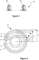
- FIG. 1 One embodiment of a few-mode optical fiber link according to the invention is schematically depicted in Figure 1 .
- the optical link 70 is built by concatenating several few-mode fibers (for example such an optical link 70 comprises p spans of optical fibers, with p ⁇ 2, which are spliced together.
- Figure 1 only shows optical fiber 701 and optical fiber 70p, all the other potential optical fibers i ⁇ 1; p in the optical link being symbolized by dashed lines).
- Few-mode fiber 1 has a length L 1
- few-mode fiber i has a length L i
- few-mode fiber p has a length L p .
- at least one of the optical fibers 1 to p in link 70 has an optical core radius R 1 i such that R 1 i ⁇ 13,5 ⁇ m, i ⁇ 1; p .
- the present disclosure encompasses any number of few-mode fibers concatenated to form an optical link; as a mere example, such a link may comprise only two FMFs, four FMFs, or even several tens of FMFs.
- the optical fiber 10 generally has a glass core 20 surrounded by a glass cladding.
- the glass core 20 generally has a radius R 1 from about 13,5 ⁇ m to about 20 ⁇ m.
- the cladding generally has an inner radius R 1 and an outer radius R 4 .
- the core 20 and the cladding generally comprise silica, specifically silica glass.
- the cross-section of the optical fiber 10 may be generally circular-symmetric with respect to the center of the core 20.
- the radius R 4 i.e. the radius of the glass portion of the optical fiber 10.
- the optical fiber 10 also comprises a coating 60 of inner radius R 4 and of outer radius R 5 .
- a coating may comprise several layers, and it may notably be a dual-layer coating, although these different layers are not shown on figure 2 .
- R 4 and R 5 are the lower and upper limits of the coating, whatever the number of layers in-between.
- the radius R 5 is about 122,5 ⁇ m (but it could be greater or less than 122,5 ⁇ m).
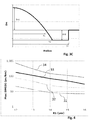
- Figure 3A depicts the refractive index profile n(r) of optical fiber 10 according to a first embodiment of the invention. It describes the relationship between the refractive index value n and the distance r from the center of the optical fiber.
- the alpha refractive index profile of the optical core 20 allows reducing intermodal dispersion of the optical fiber 10.
- the optical core 20 is directly surrounded by an optical cladding, which comprises at least a depressed-index ring 40, also called a trench, with inner radius R 2 and outer radius R 3 , and an outer cladding layer 50 with inner radius R 3 .
- an outer cladding layer 50 comprises pure silica glass (SiO 2 ) and its refractive index n Cl is hence that of silica glass.
- the trench 40 is designed so as to fulfill the following criterion: 55 ⁇ 1000.
- ⁇ ⁇ C
- the cladding may also optionally include an inner cladding layer 30, with inner radius R 1 and outer radius R 2 .
- the trench 40 may hence be spaced apart from the core 20 by the inner cladding layer 30. Alternatively, the trench 40 may surround and directly contact the core portion 20.
- the different portions 30, 40, 50 in the cladding may comprise pure silica glass (SiO 2 ), silica glass with one or more dopants, which increase the index of refraction (e.g. GeO 2 or any other known dopant), such as when the portion of the cladding is "up-doped", or silica glass with a dopant, which decreases the index of refraction, such as fluorine, such as when the portion of the cladding is "down-doped” (e.g. for the trench 40).
- dopants which increase the index of refraction
- germanO 2 or any other known dopant such as when the portion of the cladding is "up-doped”
- silica glass with a dopant which decreases the index of refraction, such as fluorine, such as when the portion of the cladding is "down-doped” (e.g. for the trench 40).
- the outer cladding 50 may also comprise other portions or layers of lower or higher refractive indexes, for r > R 3 .
- the minimal refractive index of the core n 1 is equal to the refractive index of the outer cladding n Cl .
- the down-doped trench 40 can provide lower bending loss.
- Figure 3B depicts the refractive index profile n(r) of an optical fiber according to a second embodiment of the invention.
- n(r) the refractive index profile of an optical fiber according to a second embodiment of the invention.
- Such a profile differs from that of the first embodiment in that the minimal refractive index of the core n 1 is not equal to the refractive index of the outer cladding n Cl but may either show a negative or a positive (shown in dashed lines on figure 2B ) refractive index difference with respect to the optical fiber outer cladding.
- the cladding comprises an inner cladding layer 30
- the outer cladding 50 may also comprise other portions or layers of lower or higher refractive indexes, for r > R 3 .
- the trench 40 is preferably designed so as to fulfill the following criterion: 55 ⁇ 1000.
- Figure 3C depicts the refractive index profile n(r) of an optical fiber according to a third embodiment of the invention.
- n(r) the refractive index profile of an optical fiber according to a third embodiment of the invention.
- the term "single-a graded-index profile" has a slightly different meaning as compared to the first two embodiments, since this graded-index profile goes beyond the optical core until the outer edge of the inner cladding layer.
- the optical cladding also comprises at least a depressed-index ring 40, with inner radius R 2 and outer radius R 3 , and an outer cladding layer 50 with inner radius R 3 .
- an outer cladding layer 50 comprises pure silica glass (SiO 2 ) and its refractive index n Cl is hence that of silica glass.
- the outer cladding 50 may also comprise other portions or layers of lower or higher refractive indexes, for r > R 3 .
- the trench 40 is preferably designed so as to fulfill the following criterion: 55 ⁇ 1000.
- Figure 4 illustrates how the maximum of the Differential Mode Group Delays Max
- the x-axis depicts the core radius of the fiber R 1 , ranging from 12 to 16 ⁇ m.
- the y-axis depicts the Max
- Curve 31 corresponds to a FMF guiding 6 LP modes
- curve 32 corresponds to a FMF guiding 9 LP modes
- curve 33 corresponds to a FMF guiding 12 LP modes
- curve 34 corresponds to a FMF guiding 16 LP modes.
- the x-axis depicts the core radius of the fiber R 1 , ranging from 12 to 16 ⁇ m.
- the y-axis depicts the C criterion ranging from 0 to 30.
- Curve 41 corresponds to a FMF guiding 6 LP modes
- curve 42 corresponds to a FMF guiding 9 LP modes
- curve 43 corresponds to a FMF guiding 12 LP modes
- curve 44 corresponds to a FMF guiding 16 LP modes.
- the normalized frequency V 2 ⁇ R 1 ⁇ n 0 2 ⁇ n Cl 2 , where ⁇ is the operating wavelength) is preferably between 7.8 and 9.8.
- is preferably ⁇ 25ps/km, and more preferably ⁇ 15ps/km, at ⁇ , here 1550nm. More generally, such values can be achieved for any central transmission wavelength ⁇ C of any operating wavelength band for which the optical fiber is intended, such as the C-band, or the L-, S-, or U-band for example.
- is also preferably ⁇ 50ps/km and more preferably ⁇ 30ps/km from 1530 to 1570nm.
- is preferably ⁇ 100ps/km, and more preferably ⁇ 60ps/km, at ⁇ , here 1550nm (and more generally for any central transmission wavelength ⁇ C of any operating wavelength band for which the optical fiber is intended).
- is also preferably ⁇ 200ps/km and more preferably ⁇ 120ps/km from 1530 to 1570nm.
- is preferably ⁇ 150ps/km and more preferably ⁇ 120ps/km, at ⁇ , here 1550nm. More generally, such values can be achieved for any central transmission wavelength ⁇ C of any operating wavelength band for which the optical fiber is intended, such as the C-band, or the L-, S-, or U-band for example. Max
- is preferably ⁇ 300ps/km and more preferably ⁇ 250ps/km, at ⁇ , here 1550nm. More generally, such values can be achieved for any central transmission wavelength ⁇ C of any operating wavelength band for which the optical fiber is intended, such as the C-band, or the L-, S-, or U-band for example. Max
- the normalized frequency V is preferably between 5.7 and 7.8.
- is preferably ⁇ 20ps/km, and more preferably ⁇ 10ps/km, at 1550nm. More generally, such values can be achieved for any central transmission wavelength ⁇ C of any operating wavelength band for which the optical fiber is intended, such as the C-band, or the L-, S-, or U-band for example. Max
- All LP guided modes of FMFs according to an embodiment of the invention have effective areas, A eff ⁇ 400 ⁇ m 2 , preferably ⁇ 350 ⁇ m 2 , and bend losses ⁇ 100dB/turn, preferably ⁇ 50dB/turn, at 10mm bend radius at 1550nm, and all LP leakage modes have leakage losses >0.1dB/m, preferably >0.5dB/m, at 1550nm, so that they are cut-off after few tens of meters of propagation (>19.34dB (Leakage) loss).
- the effective area of an optical fiber is the area of the optical fiber in which light is propagated and is determined at the specified mode (e.g. LP 01 ), at a wavelength of 1550nm, unless otherwise specified.
- Table 1 gives the parameters of the index profiles of examples of FMFs according to the embodiment of Figure 3B , and results on Max
- the trade-off between the bend losses and the leakage losses is much more easily met.
- Table 2 gives the characteristics of the LP modes of the Examples of Table 1 supporting 4 LP guided modes, i.e. modes LP 01 , LP 11 , LP 21 and LP 02 .
- Table 2 Ex.0 Dneff Leakage Loss A eff CD Bend Loss DMGD vs.
- LP01 ( ⁇ 10 -3 ) (dB/m) ( ⁇ m 2 ) (ps/nm-km) (dB/turn) (ps/km)
- Dneff stands for the effective index difference
- CD stands for the chromatic dispersion expressed as ps/nm-km (chromatic dispersion is the sum of the material dispersion, the waveguide dispersion and the inter-modal dispersion)
- Bend Losses expressed as dB/turn, are given at 10mm bend radius.
- a eff expressed as ⁇ m 2 designates the effective area of the LP guided mode.
- the Differential Mode Group Delay DMGD is measured with respect to the first guided mode LP 01 and expressed as ps/km.
- LP 12 and LP 31 are leaky modes.
- Table 3 Ex.1 Oneff ( ⁇ 10 -3 ) Leakage Loss (dB/m) A eff ( ⁇ m 2 ) CD (ps/nm-km) Bend Loss (dB/turn) DMGD vs.
- LP 03 , LP 22 and LP 41 are leaky modes.
- LP 13 , LP 32 and LP 51 are leaky modes.
- Table 5 gives the characteristics of the LP modes of the Examples of Table 1 supporting 12 LP guided modes (examples 6 and 7).
- LP 04 , LP 23 , LP 42 and LP 61 are leaky modes.
- Table 6 gives the characteristics of the LP modes of the Examples of Table 1 supporting 16 LP guided modes (examples 8, 9 and 10).
- LP 14 , LP 33 , LP 52 and LP 71 are leaky modes Table 6: Ex.8 Dneff ( ⁇ 10 -3 ) Leakage Loss (dB/m) A eff ( ⁇ m 2 ) CD (ps/nm-km) Bend Loss (dB/turn) DMGD vs.
- Figure 6 illustrates the evolution of Max
- the x-axis depicts the wavelength of the light guided by the fiber, ranging from 1530 to 1570nm.
- the ⁇ -axis depicts the Max
- Curve 51 corresponds to the FMF guiding 6 LP modes of Example 2;
- curve 52 corresponds to the FMF guiding 9 LP modes of Example 5;
- curve 53 corresponds to the FMF guiding 12 LP modes of Example 6, while curve 54 corresponds to the FMF guiding 16 LP modes of Example 9.
- remains low in the entire extended C-band from 1530 to 1570nm.
- slope in this extended C-band is in absolute value ⁇ 3ps/km/nm, preferably ⁇ 2ps/km/nm, and more preferably ⁇ 1ps/km/nm.
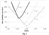
- Figure 7 depicts the evolution of Max
- the x-axis depicts the value of ⁇ , which is a non-dimensional parameter that defines the index profile shape of the graded-index optical core, with ⁇ ranging from 1,91 to 1,99.
- the ⁇ -axis depicts the Max
- Curve 61 corresponds to the FMF guiding 6 LP modes of Example 2;
- curve 62 corresponds to the FMF guiding 9 LP modes of Example 4;
- curve 63 corresponds to the FMF guiding 12 LP modes of Example 7, while curve 64 corresponds to the FMF guiding 16 LP modes of Example 8.
- the few mode optical fibers 10 according to the disclosure have a low loss and a small differential group delay, and are suitable for use in optical transmission systems, particularly those that utilize space-division multiplexing and that are configured for long-haul transmission.
- of the link can then be very close to the minimum value shown on figure 7 .
- This association can, for instance, compensate for process variability that may result in FMFs with slightly off-target Alphas.
- Tables 6, 7, 8 & 9 show examples of these associations for FMFs supporting 6, 9, 12 and 16 LP guided modes, respectively.
- Table 6: Ex.2 Alpha Opt 1.951 Alpha Off-Target 1.956 Alpha Comp 1.910 Combination of Alphas with L Comp /L Opt 0.128 DMGD vs. LP01 (ps/km) DMGD vs. LP01 (ps/km) DMGD vs. LP01 (ps/km) DMGD vs. LP01 (ps/km) DMGD vs.
- Table 6 shows the values of DMGDs and Max
- Column 2 of table 6 gives the values of DMGDs and Max
- at a wavelength ⁇ 1550 nm for a FMF according to Example 2 showing an optimum value of ⁇ .
- the last column in table 6 gives the values of DMGDs and Max
- at a wavelength ⁇ 1550 nm for an optical link built by concatenating the FMF in column 3 with a length L opt and the FMF in column 4 with a length L comp .
- Such a ratio is chosen so as to be equal to, or very close to, the ratio of the absolute values of the DMGDs of the modes having the highest DMGDs values for both fibers in the link.
- a highest mode is the LP 31 mode, for which the ratio of the absolute values of the DMGDs for both fibers in the optical link is
- 0,13.
- we choose a ratio of the optical fibers lengths close to 0,13, such that L comp / L opt 0,128.
- the lengths L opt and L comp are hence chosen so as to minimize Max
- for the DMGD-compensated optical link are hence very close to the minimum values.
- Such an optical link allows guiding six LP modes, with a very low DGMD, and thus a very good system reach.
- Such an optical link meets the core criterion C ⁇ 18, and is made up of two FMFs, which both individually meet the core criterion C ⁇ 18.
- Table 7 shows the values of DMGDs and Max
- at a wavelength ⁇ 1550 nm for a FMF according to Example 4 showing an optimum value of ⁇ .
- the last column in table 7 gives the values of DMGDs and Max
- at a wavelength ⁇ 1550 nm for an optical link built by concatenating the FMF in column 3 with a length L opt and the FMF in column 4 with a length L comp .
- Such a ratio is chosen equal to, or very close to, the ratio of the absolute values of the DMGDs of the modes having the highest DMGDs values for both fibers in the link.
- a highest mode is the LP 41 mode, for which the ratio of the absolute values of the DMGDs for both fibers in the optical link is
- 0,13.
- L comp / L opt 0,134.
- the lengths L opt and L comp are hence chosen so as to minimize Max
- for the DMGD-compensated optical link are hence very close to the minimum values.
- Such an optical link allows guiding nine LP modes, with a very low DGMD, and thus a very good system reach.
- Such an optical link meets the core criterion C ⁇ 18, and is made up of two FMFs, which both individually meet the core criterion C ⁇ 18.
- Table 8 Ex.7 Alpha Opt 1.934 Alpha Off-Target 1.942 Alpha Comp 1.900 Combination of Alphas with 10.230 DMGD vs. LP01 (ps/km) DMGD vs. LP01 (ps/km) DMGD vs. LP01 (ps/km) DMGD vs. LP01 (ps/km) DMGD vs.
- Table 8 shows the values of DMGDs and Max
- Column 2 of table 8 gives the values of DMGDs and Max
- at a wavelength ⁇ 1550 nm for a FMF according to Example 7 showing an optimum value of ⁇ .
- the last column in table 8 gives the values of DMGDs and Max
- at a wavelength ⁇ 1550 nm for an optical link built by concatenating the FMF in column 3 with a length L opt and the FMF in column 4 with a length L comp .
- Such a ratio is chosen equal to, or very close to, the ratio of the absolute values of the DMGDs of the modes having the highest DMGDs values for both fibers in the link.
- a highest mode is the LP 51 mode, for which the ratio of the absolute values of the DMGDs for both fibers in the optical link is
- 0,25.
- L comp / L opt 0,230.
- the lengths L opt and L comp are hence chosen so as to minimize Max
- for the DMGD-compensated optical link are very close to the minimum values.
- Such an optical link allows guiding twelve LP modes, with a very low DGMD, and thus a very good system reach.
- Such an optical link meets the core criterion C ⁇ 18, and is made up of two FMFs, which both individually meet the core criterion C ⁇ 18.
- Table 9 shows the values of DMGDs and Max
- Column 2 of table 9 gives the values of DMGDs and Max
- at a wavelength ⁇ 1550 nm for a FMF according to Example 8 showing an optimum value of ⁇ .
- the last column in table 9 gives the values of DMGDs and Max
- at a wavelength ⁇ 1550 nm for an optical link built by concatenating the FMF in column 3 with a length L opt and the FMF in column 4 with a length L comp .
- Such a ratio is chosen equal to, or very close to, the ratio of the absolute values of the DMGDs of the modes having the highest DMGDs values for both fibers in the link.
- a highest mode is the LP 61 mode, for which the ratio of the absolute values of the DMGDs for both fibers in the optical link is
- 0,15.
- the lengths L opt and L comp are hence chosen so as to minimize Max
- for the DMGD-compensated optical link are very close to the minimum values.
- Such an optical link allows guiding sixteen LP modes, with a very low DGMD, and thus a very good system reach.
- Such an optical link meets the core criterion C ⁇ 18, and is made up of two FMFs, which both individually meet the core criterion C ⁇ 18.
- optical links described above in relation to tables 6, 7, 8 and 9 are hence all built by concatenating two FMFs having the same overall refractive index profile, according to any of the embodiments of figures 3A to 3C , having the same radii R 1 , R 2 and R 3 and index differences Dn 1 , Dn 2 and Dn 3 , but having slightly different values of ⁇ , one with a value of ⁇ slightly lower than the optimum ⁇ , and one with a value of ⁇ slightly higher than the optimum ⁇ , so that the DMGDs with opposite signs can compensate each other. It is thus possible to build a DMGD-compensated link with robust features.
- FMFs having the same value for ⁇ , but having different values of R 1 or of Dn 1 for example.
- the same DMGD compensation can occur by choosing the appropriate optical fiber lengths.
- FMFs having any of the refractive index profiles of figures 3A to 3C it is possible to associate FMFs having any of the refractive index profiles of figures 3A to 3C . It is also possible to associate one or several FMFs having one of the refractive index profiles of figures 3A to 3C , with any other FMF having an optical core with a single ⁇ graded-index profile and an optical cladding comprising a trench.
- optical fibers which individually satisfy the criteria R 1 i ⁇ 13,5 ⁇ m and C ⁇ 18, or which do not individually satisfy such criteria, or for which one, or several of them only, individually satisfy such criteria.
- FIGS 8A and 8B illustrate embodiments of an optical system according to the invention.
- an optical system comprises transceivers 81 and receivers 85 optically connected by an optical fiber link 70 that includes at least two spans of fiber.
- Transceivers 81 comprise light sources (such as lasers) and generate n LP modes, referenced 1, 2, ..., n used in the optical system of figure 8A .
- a mode multiplexer 82 multiplexes the n LP modes and is optically connected to optical link 70, which guides the n multiplexed LP modes, towards a mode demultiplexer 83, which is optically connected to the end of optical link 70.
- Mode demultiplexer 83 demultiplexes the n multiplexed LP modes, and feeds each LP mode into an amplifier 84. At the output of amplifiers 84, LP modes enter receivers 85.
- Such an optical system may comprise M optical links.
- the optical system comprises M optical links, it also comprises M mode multiplexers 82, M mode demultiplexers 83, and M amplifiers 84 for each LP mode guided by the optical system.
- the embodiment in figure 8B differs from the first embodiment in figure 8A in that amplifier 84 amplifies all LP modes guided by the optical link 70; as such, amplifier 84 is optically connected between the output of optical link 70 and the input of mode demultiplexer 83.
- amplifier 84 when the optical system comprises M optical links, it also comprises M amplifiers 84; however, there is only one mode multiplexer 82, optically connected between transceivers 81 an optical link 70, and only one mode demultiplexer 83, optically connected between amplifier 84 and receivers 85.
Landscapes
- Physics & Mathematics (AREA)
- General Physics & Mathematics (AREA)
- Optics & Photonics (AREA)
- Engineering & Computer Science (AREA)
- Computer Networks & Wireless Communication (AREA)
- Signal Processing (AREA)
- Chemical & Material Sciences (AREA)
- Dispersion Chemistry (AREA)
- Optical Communication System (AREA)
- Optical Couplings Of Light Guides (AREA)
- Mechanical Coupling Of Light Guides (AREA)
Claims (13)
- Liaison optique comprenant N fibres optiques, avec N ≥ 2, N étant un entier,
chaque fibre optique comprenant un coeur optique et une gaine optique entourant le coeur optique, le coeur optique ayant un profil à gradient d'indice αi unique avec αi ≥ 1, αi étant un paramètre non dimensionnel qui définit la forme de profil d'indice du coeur optique, et le coeur optique ayant un rayon R1i et un indice de réfraction maximal n0i, où i ∈1; N est un indice désignant ladite fibre optique,
ladite gaine optique ayant au niveau de son bord extérieur un indice de réfraction nCli,
dans laquelle ladite gaine optique comprend une région d'indice de réfraction en creux ntrenchi, appelée une tranchée, entourant le coeur optique, ladite tranchée ayant un rayon intérieur R2i, avec R2i ≥ R1i, et un rayon extérieur R3i, avec R3i > R2i,
ladite liaison optique étant caractérisée en ce qu'un rayon de coeur optique moyen R1link pour ladite liaison optique, exprimé en microns, satisfait un critère C de qualité de communications optiques défini par l'équation suivante :
où Max|DMGDlinkl est une valeur maximale absolue de temps de propagation de groupe en mode différentiel entre n'importe quelle combinaison de modes guidés dans ladite liaison optique, exprimée en ps/km,
où
et où
en ce que, pour au moins une fibre optique i dans ladite liaison, ledit rayon de coeur optique R1i est choisi de manière que R1i ≥ 13,5 µm et pour toutes les fibres optiques i ∈1; Ndans ladite liaison, ladite longueur Li est choisie de manière que C ≤ 18,
et en ce que ladite liaison optique guide au moins 4 modes LP. - Liaison optique selon la revendication 1, dans laquelle au moins une desdites fibres optiques a des paramètres de tranchée satisfaisant la relation suivante :

et où les rayons R1i, R2i et R3i sont exprimés en microns. - Liaison optique selon la revendication 2, dans laquelle Dn3 ≤ -3.10-3.
- Liaison optique selon l'une quelconque des revendications 1 à 3, dans laquelle au moins une desdites fibres optiques a un rayon de coeur optique R1i et une valeur αi dudit profil à gradient d'indice de manière que :

où Max|DMGDi| est la valeur maximale absolue de DMGD entre n'importe quelle combinaison de modes guidés dans ladite fibre optique, exprimée en ps/km,
et où Dn1i = n0i - nCli est la différence d'indice coeur-gaine à λ = λC pour ladite fibre optique. - Liaison optique selon la revendication 4, dans laquelle ladite fibre optique est telle que R1i ≤ 20 µm.
- Liaison optique selon l'une quelconque des revendications 1, 4 et 5, dans laquelle elle guide 4 à 16 modes LP.
- Liaison optique selon l'une quelconque des revendications 1 à 5, dans laquelle elle guide au moins 6 modes LP, et de préférence 6 à 16 modes LP.
- Liaison optique selon l'une quelconque des revendications 1 à 7, dans laquelle, pour toutes les fibres optiques i ∈1; Ndans ladite liaison, lesdites longueurs Li sont choisies de manière à minimiser Max|DMGDlink| sur ladite liaison.
- Liaison optique selon l'une quelconque des revendications 1 à 8, dans laquelle au moins deux fibres optiques dans ladite liaison ont un DMGDi présentant des signes opposés pour au moins un mode guidé par lesdites fibres optiques, où DMGDi est le temps de propagation de groupe en mode différentiel entre ledit un mode et n'importe quel autre mode guidé dans une fibre optique i.
- Liaison optique selon l'une quelconque des revendications 1 à 9, dans laquelle, pour au moins une desdites fibres i ∈1; Ndans ladite liaison optique, ledit coeur optique a un indice de réfraction minimal n1i = nCli, et ladite gaine optique comprend également une couche de gaine intérieure entourant directement ledit coeur optique, avec un rayon intérieur R1i et un rayon extérieur R2i ≥ R1i, ladite couche de gaine intérieure ayant un indice de réfraction constant n2i, de manière que n2i ≠ nCli et n2i > ntrenchi.
- Liaison optique selon l'une quelconque des revendications 1 à 9, dans laquelle, pour au moins une desdites fibres i ∈1; Ndans ladite liaison optique, ledit coeur optique a un indice de réfraction minimal nli + nCli, et ladite gaine optique comprend également une couche de gaine intérieure entourant directement ledit coeur optique, avec un rayon intérieur R1i et un rayon extérieur R2i ≥ R1i, ladite couche de gaine intérieure ayant un indice de réfraction constant n2i, de manière que n2i = nli et n2i > ntrenchi.
- Liaison optique selon l'une quelconque des revendications 1 à 10, dans laquelle, pour au moins une desdites fibres i ∈1; Ndans ladite liaison optique, ledit coeur optique a un indice de réfraction minimal qui est égal à nCli, ladite gaine optique comprend également une couche de gaine intérieure entourant directement ledit coeur optique, avec un rayon intérieur R1i et un rayon extérieur R2i ≥ R1i, ladite couche de gaine intérieure étant une extension dudit profil à gradient d'indice αi unique dudit coeur optique, et ladite couche intérieure a un indice de réfraction minimal n1i = ntrenchi.
- Système optique comprenant au moins une liaison optique selon l'une quelconque des revendications 1 à 12.
Applications Claiming Priority (1)
| Application Number | Priority Date | Filing Date | Title |
|---|---|---|---|
| PCT/IB2013/002413 WO2015040447A1 (fr) | 2013-09-20 | 2013-09-20 | Liaisons de fibres optiques à nombre de modes restreint de multiplexage spatial |
Publications (2)
| Publication Number | Publication Date |
|---|---|
| EP3047317A1 EP3047317A1 (fr) | 2016-07-27 |
| EP3047317B1 true EP3047317B1 (fr) | 2018-01-31 |
Family
ID=50151321
Family Applications (1)
| Application Number | Title | Priority Date | Filing Date |
|---|---|---|---|
| EP13831834.0A Active EP3047317B1 (fr) | 2013-09-20 | 2013-09-20 | Liaisons de fibres optiques à nombre de modes restreint de multiplexage spatial |
Country Status (8)
| Country | Link |
|---|---|
| US (1) | US10007055B2 (fr) |
| EP (1) | EP3047317B1 (fr) |
| JP (1) | JP6397899B2 (fr) |
| CN (1) | CN105683791B (fr) |
| BR (1) | BR112016006066B1 (fr) |
| DK (1) | DK3047317T3 (fr) |
| ES (1) | ES2667796T3 (fr) |
| WO (1) | WO2015040447A1 (fr) |
Families Citing this family (21)
| Publication number | Priority date | Publication date | Assignee | Title |
|---|---|---|---|---|
| US9671552B2 (en) * | 2012-09-05 | 2017-06-06 | Ofs Fitel, Llc | 9 LP-mode fiber designs for mode-division multiplexing |
| US9678269B2 (en) | 2014-05-16 | 2017-06-13 | Corning Incorporated | Multimode optical fiber transmission system including single mode fiber |
| US20150331181A1 (en) * | 2014-05-16 | 2015-11-19 | Corning Incorporated | Multimode optical fiber and system including such |
| WO2016106714A1 (fr) * | 2014-12-31 | 2016-07-07 | 华为技术有限公司 | Procédé, appareil, et système de transmission de données |
| CN104793285B (zh) * | 2015-04-29 | 2018-01-02 | 武汉邮电科学研究院 | 低损耗少模光纤 |
| US9804326B2 (en) * | 2015-06-23 | 2017-10-31 | Corning Incorporated | Optical fiber for multimode and single-mode transmission |
| WO2017137794A1 (fr) * | 2016-02-08 | 2017-08-17 | Draka Comteq Bv | Fibres optiques à peu de modes pour multiplexage par division de mode |
| CN106253973B (zh) * | 2016-07-25 | 2018-09-18 | 暨南大学 | 一种长距离少模光纤特性测量方法及装置 |
| CN106019475B (zh) * | 2016-07-28 | 2019-04-02 | 江苏大学 | 一种少模光纤器件 |
| CN109937372B (zh) * | 2016-11-04 | 2020-12-29 | 德拉克通信法国集团公司 | 耦合少模光纤以及相应的光链路和光学系统 |
| WO2018222981A1 (fr) * | 2017-06-02 | 2018-12-06 | Commscope Technologies Llc | Fibre concentrique pour communications optiques multiplexées par répartition spatiale et procédé d'utilisation |
| US11181686B2 (en) * | 2018-04-30 | 2021-11-23 | Corning Incorporated | Small diameter low attenuation optical fiber |
| EP3788421B1 (fr) * | 2018-04-30 | 2023-11-08 | Corning Incorporated | Fibre optique de petit diamètre à faible atténuation |
| CN112424658A (zh) | 2018-04-30 | 2021-02-26 | 康宁股份有限公司 | 外直径小的低衰减光纤 |
| US11036000B2 (en) | 2019-01-16 | 2021-06-15 | Corning Incorporated | Optical fiber cable with high fiber count |
| US11194107B2 (en) | 2019-08-20 | 2021-12-07 | Corning Incorporated | High-density FAUs and optical interconnection devices employing small diameter low attenuation optical fiber |
| CN114930218B (zh) | 2020-01-07 | 2024-05-03 | 康宁股份有限公司 | 具有高的机械可靠性的半径减小的光纤 |
| US11237324B2 (en) * | 2020-01-31 | 2022-02-01 | Sterlite Technologies Limited | Few mode optical fiber |
| US11888584B2 (en) * | 2020-02-18 | 2024-01-30 | Nippon Telegraph And Telephone Corporation | Optical transmission system, optical transmission apparatus and optical transmission method |
| WO2021231083A1 (fr) | 2020-05-12 | 2021-11-18 | Corning Incorporated | Fibres optiques monomodes à diamètre réduit à haute fiabilité mécanique |
| CN114448501B (zh) * | 2020-11-04 | 2024-04-19 | 中国移动通信有限公司研究院 | 简并模式内差分模式时延的测量方法及装置 |
Family Cites Families (23)
| Publication number | Priority date | Publication date | Assignee | Title |
|---|---|---|---|---|
| JPS53131054A (en) * | 1977-04-21 | 1978-11-15 | Nippon Telegr & Teleph Corp <Ntt> | Construction of wide range transmission passage of graded index multi- mode fiber |
| FR2864254B1 (fr) * | 2003-12-23 | 2006-03-03 | Cit Alcatel | Fibre optique multimode hom a gestion de dispersion |
| US7187833B2 (en) * | 2004-04-29 | 2007-03-06 | Corning Incorporated | Low attenuation large effective area optical fiber |
| US7406237B2 (en) * | 2006-02-21 | 2008-07-29 | Corning Incorporated | Multiband optical fiber |
| CN101446663B (zh) * | 2008-11-13 | 2012-02-22 | 富通集团有限公司 | 一种改进的具有大模场分布的非零色散位移单模光纤 |
| FR2941541B1 (fr) * | 2009-01-27 | 2011-02-25 | Draka Comteq France | Fibre optique monomode |
| US7689085B1 (en) * | 2009-01-30 | 2010-03-30 | Corning Incorporated | Large effective area fiber with GE-free core |
| CN102844689B (zh) | 2010-01-27 | 2015-07-15 | 中弗罗里达州大学研究基金会 | 利用少模光纤的光传输 |
| US8301723B2 (en) | 2010-02-26 | 2012-10-30 | Research In Motion Limited | Computer to handheld device virtualization system |
| FR2971061B1 (fr) * | 2011-01-31 | 2013-02-08 | Draka Comteq France | Fibre optique a large bande passante et a faibles pertes par courbure |
| CN103649797A (zh) | 2011-02-24 | 2014-03-19 | Ofs飞泰尔公司 | 用于空间多路复用的阶跃折射率少模光纤设计 |
| EP2503368A1 (fr) * | 2011-03-24 | 2012-09-26 | Draka Comteq B.V. | Fibre optique multimodale dotée d'une résistance améliorée à la flexion |
| EP2521289B1 (fr) * | 2011-05-04 | 2014-03-05 | Alcatel Lucent | Récepteur optique pour communications multimode |
| US8670643B2 (en) * | 2011-05-18 | 2014-03-11 | Corning Incorporated | Large effective area optical fibers |
| US8705922B2 (en) | 2011-06-21 | 2014-04-22 | Corning Incorporated | Few-moded optical fibers |
| US8693834B2 (en) | 2011-08-15 | 2014-04-08 | Corning Incorporated | Few mode optical fibers for mode division multiplexing |
| US8837892B2 (en) | 2011-09-16 | 2014-09-16 | Corning Incorporated | Few mode optical fibers for mode division multiplexing |
| US8995803B2 (en) * | 2012-02-19 | 2015-03-31 | Corning Incorporated | Mode delay managed few moded optical fiber link |
| EP2817665B1 (fr) * | 2012-02-20 | 2018-12-12 | Corning Incorporated | Liaison par fibres optiques à nombre de modes restreint et à gestion du temps de propagation de groupe modal |
| JP5789626B2 (ja) * | 2013-03-01 | 2015-10-07 | 株式会社フジクラ | 光ファイバおよび光伝送路 |
| EP3047316B1 (fr) * | 2013-09-20 | 2018-01-17 | Draka Comteq BV | Fibres optiques multimodales pour multiplexage de division d'espace |
| US9470841B2 (en) * | 2013-12-06 | 2016-10-18 | Cornning Incorporated | Multicore optical fiber with multimode cores |
| US9813157B2 (en) * | 2015-03-06 | 2017-11-07 | Nec Corporation | Mitigation of multi-path interference from quasi-single-mode fiber using hybrid span configuration and digital signal processing |
-
2013
- 2013-09-20 EP EP13831834.0A patent/EP3047317B1/fr active Active
- 2013-09-20 US US15/023,126 patent/US10007055B2/en active Active
- 2013-09-20 JP JP2016515546A patent/JP6397899B2/ja active Active
- 2013-09-20 ES ES13831834.0T patent/ES2667796T3/es active Active
- 2013-09-20 CN CN201380080353.0A patent/CN105683791B/zh active Active
- 2013-09-20 BR BR112016006066-0A patent/BR112016006066B1/pt active IP Right Grant
- 2013-09-20 WO PCT/IB2013/002413 patent/WO2015040447A1/fr active Application Filing
- 2013-09-20 DK DK13831834.0T patent/DK3047317T3/en active
Also Published As
| Publication number | Publication date |
|---|---|
| US20160231503A1 (en) | 2016-08-11 |
| BR112016006066A2 (pt) | 2017-08-01 |
| JP2016537660A (ja) | 2016-12-01 |
| CN105683791A (zh) | 2016-06-15 |
| DK3047317T3 (en) | 2018-04-23 |
| CN105683791B (zh) | 2019-01-11 |
| US10007055B2 (en) | 2018-06-26 |
| ES2667796T3 (es) | 2018-05-14 |
| EP3047317A1 (fr) | 2016-07-27 |
| BR112016006066B1 (pt) | 2022-02-22 |
| JP6397899B2 (ja) | 2018-09-26 |
| WO2015040447A1 (fr) | 2015-03-26 |
Similar Documents
| Publication | Publication Date | Title |
|---|---|---|
| EP3047317B1 (fr) | Liaisons de fibres optiques à nombre de modes restreint de multiplexage spatial | |
| EP3047316B1 (fr) | Fibres optiques multimodales pour multiplexage de division d'espace | |
| US10324253B2 (en) | Few mode optical fibers for mode division multiplexing having intermediate trenches | |
| US6483975B1 (en) | Positive dispersion optical fiber having large effective area | |
| US6633715B2 (en) | Optical fiber having negative dispersion, negative dispersion slope and large effective area | |
| EP1396743B1 (fr) | Fibre optique à compensation de dispersion | |
| EP3637161B1 (fr) | Fibres optiques à peu de modes faiblement couplées pour multiplexage par répartition de mode et système de transmission optique correspondant | |
| EP3414604B1 (fr) | Fibres optiques à peu de modes pour multiplexage par division de mode | |
| WO2007005332A2 (fr) | Fibre optique a dispersion decalee non nulle | |
| US10871611B2 (en) | Weakly coupled few-mode fibers for space-division multiplexing |
Legal Events
| Date | Code | Title | Description |
|---|---|---|---|
| PUAI | Public reference made under article 153(3) epc to a published international application that has entered the european phase |
Free format text: ORIGINAL CODE: 0009012 |
|
| 17P | Request for examination filed |
Effective date: 20160315 |
|
| AK | Designated contracting states |
Kind code of ref document: A1 Designated state(s): AL AT BE BG CH CY CZ DE DK EE ES FI FR GB GR HR HU IE IS IT LI LT LU LV MC MK MT NL NO PL PT RO RS SE SI SK SM TR |
|
| AX | Request for extension of the european patent |
Extension state: BA ME |
|
| DAX | Request for extension of the european patent (deleted) | ||
| RIC1 | Information provided on ipc code assigned before grant |
Ipc: G02B 6/02 20060101AFI20170628BHEP Ipc: H04J 14/04 20060101ALI20170628BHEP Ipc: G02B 6/028 20060101ALI20170628BHEP Ipc: G02B 6/036 20060101ALI20170628BHEP Ipc: H04J 14/00 20060101ALI20170628BHEP |
|
| GRAP | Despatch of communication of intention to grant a patent |
Free format text: ORIGINAL CODE: EPIDOSNIGR1 |
|
| INTG | Intention to grant announced |
Effective date: 20170821 |
|
| GRAS | Grant fee paid |
Free format text: ORIGINAL CODE: EPIDOSNIGR3 |
|
| GRAJ | Information related to disapproval of communication of intention to grant by the applicant or resumption of examination proceedings by the epo deleted |
Free format text: ORIGINAL CODE: EPIDOSDIGR1 |
|
| GRAL | Information related to payment of fee for publishing/printing deleted |
Free format text: ORIGINAL CODE: EPIDOSDIGR3 |
|
| GRAR | Information related to intention to grant a patent recorded |
Free format text: ORIGINAL CODE: EPIDOSNIGR71 |
|
| GRAA | (expected) grant |
Free format text: ORIGINAL CODE: 0009210 |
|
| INTC | Intention to grant announced (deleted) | ||
| INTG | Intention to grant announced |
Effective date: 20171219 |
|
| AK | Designated contracting states |
Kind code of ref document: B1 Designated state(s): AL AT BE BG CH CY CZ DE DK EE ES FI FR GB GR HR HU IE IS IT LI LT LU LV MC MK MT NL NO PL PT RO RS SE SI SK SM TR |
|
| REG | Reference to a national code |
Ref country code: GB Ref legal event code: FG4D Ref country code: CH Ref legal event code: EP |
|
| REG | Reference to a national code |
Ref country code: AT Ref legal event code: REF Ref document number: 967896 Country of ref document: AT Kind code of ref document: T Effective date: 20180215 |
|
| REG | Reference to a national code |
Ref country code: IE Ref legal event code: FG4D |
|
| REG | Reference to a national code |
Ref country code: DE Ref legal event code: R096 Ref document number: 602013032774 Country of ref document: DE |
|
| REG | Reference to a national code |
Ref country code: DK Ref legal event code: T3 Effective date: 20180420 |
|
| REG | Reference to a national code |
Ref country code: ES Ref legal event code: FG2A Ref document number: 2667796 Country of ref document: ES Kind code of ref document: T3 Effective date: 20180514 |
|
| REG | Reference to a national code |
Ref country code: NL Ref legal event code: MP Effective date: 20180131 |
|
| REG | Reference to a national code |
Ref country code: LT Ref legal event code: MG4D |
|
| REG | Reference to a national code |
Ref country code: AT Ref legal event code: MK05 Ref document number: 967896 Country of ref document: AT Kind code of ref document: T Effective date: 20180131 |
|
| PG25 | Lapsed in a contracting state [announced via postgrant information from national office to epo] |
Ref country code: NL Free format text: LAPSE BECAUSE OF FAILURE TO SUBMIT A TRANSLATION OF THE DESCRIPTION OR TO PAY THE FEE WITHIN THE PRESCRIBED TIME-LIMIT Effective date: 20180131 Ref country code: NO Free format text: LAPSE BECAUSE OF FAILURE TO SUBMIT A TRANSLATION OF THE DESCRIPTION OR TO PAY THE FEE WITHIN THE PRESCRIBED TIME-LIMIT Effective date: 20180430 Ref country code: LT Free format text: LAPSE BECAUSE OF FAILURE TO SUBMIT A TRANSLATION OF THE DESCRIPTION OR TO PAY THE FEE WITHIN THE PRESCRIBED TIME-LIMIT Effective date: 20180131 Ref country code: HR Free format text: LAPSE BECAUSE OF FAILURE TO SUBMIT A TRANSLATION OF THE DESCRIPTION OR TO PAY THE FEE WITHIN THE PRESCRIBED TIME-LIMIT Effective date: 20180131 Ref country code: FI Free format text: LAPSE BECAUSE OF FAILURE TO SUBMIT A TRANSLATION OF THE DESCRIPTION OR TO PAY THE FEE WITHIN THE PRESCRIBED TIME-LIMIT Effective date: 20180131 |
|
| PG25 | Lapsed in a contracting state [announced via postgrant information from national office to epo] |
Ref country code: IS Free format text: LAPSE BECAUSE OF FAILURE TO SUBMIT A TRANSLATION OF THE DESCRIPTION OR TO PAY THE FEE WITHIN THE PRESCRIBED TIME-LIMIT Effective date: 20180531 Ref country code: BG Free format text: LAPSE BECAUSE OF FAILURE TO SUBMIT A TRANSLATION OF THE DESCRIPTION OR TO PAY THE FEE WITHIN THE PRESCRIBED TIME-LIMIT Effective date: 20180430 Ref country code: AT Free format text: LAPSE BECAUSE OF FAILURE TO SUBMIT A TRANSLATION OF THE DESCRIPTION OR TO PAY THE FEE WITHIN THE PRESCRIBED TIME-LIMIT Effective date: 20180131 Ref country code: PL Free format text: LAPSE BECAUSE OF FAILURE TO SUBMIT A TRANSLATION OF THE DESCRIPTION OR TO PAY THE FEE WITHIN THE PRESCRIBED TIME-LIMIT Effective date: 20180131 Ref country code: SE Free format text: LAPSE BECAUSE OF FAILURE TO SUBMIT A TRANSLATION OF THE DESCRIPTION OR TO PAY THE FEE WITHIN THE PRESCRIBED TIME-LIMIT Effective date: 20180131 Ref country code: LV Free format text: LAPSE BECAUSE OF FAILURE TO SUBMIT A TRANSLATION OF THE DESCRIPTION OR TO PAY THE FEE WITHIN THE PRESCRIBED TIME-LIMIT Effective date: 20180131 Ref country code: GR Free format text: LAPSE BECAUSE OF FAILURE TO SUBMIT A TRANSLATION OF THE DESCRIPTION OR TO PAY THE FEE WITHIN THE PRESCRIBED TIME-LIMIT Effective date: 20180501 Ref country code: RS Free format text: LAPSE BECAUSE OF FAILURE TO SUBMIT A TRANSLATION OF THE DESCRIPTION OR TO PAY THE FEE WITHIN THE PRESCRIBED TIME-LIMIT Effective date: 20180131 |
|
| REG | Reference to a national code |
Ref country code: FR Ref legal event code: PLFP Year of fee payment: 6 |
|
| PG25 | Lapsed in a contracting state [announced via postgrant information from national office to epo] |
Ref country code: AL Free format text: LAPSE BECAUSE OF FAILURE TO SUBMIT A TRANSLATION OF THE DESCRIPTION OR TO PAY THE FEE WITHIN THE PRESCRIBED TIME-LIMIT Effective date: 20180131 Ref country code: EE Free format text: LAPSE BECAUSE OF FAILURE TO SUBMIT A TRANSLATION OF THE DESCRIPTION OR TO PAY THE FEE WITHIN THE PRESCRIBED TIME-LIMIT Effective date: 20180131 Ref country code: RO Free format text: LAPSE BECAUSE OF FAILURE TO SUBMIT A TRANSLATION OF THE DESCRIPTION OR TO PAY THE FEE WITHIN THE PRESCRIBED TIME-LIMIT Effective date: 20180131 |
|
| REG | Reference to a national code |
Ref country code: DE Ref legal event code: R097 Ref document number: 602013032774 Country of ref document: DE |
|
| PG25 | Lapsed in a contracting state [announced via postgrant information from national office to epo] |
Ref country code: SM Free format text: LAPSE BECAUSE OF FAILURE TO SUBMIT A TRANSLATION OF THE DESCRIPTION OR TO PAY THE FEE WITHIN THE PRESCRIBED TIME-LIMIT Effective date: 20180131 Ref country code: CZ Free format text: LAPSE BECAUSE OF FAILURE TO SUBMIT A TRANSLATION OF THE DESCRIPTION OR TO PAY THE FEE WITHIN THE PRESCRIBED TIME-LIMIT Effective date: 20180131 Ref country code: SK Free format text: LAPSE BECAUSE OF FAILURE TO SUBMIT A TRANSLATION OF THE DESCRIPTION OR TO PAY THE FEE WITHIN THE PRESCRIBED TIME-LIMIT Effective date: 20180131 |
|
| PLBE | No opposition filed within time limit |
Free format text: ORIGINAL CODE: 0009261 |
|
| STAA | Information on the status of an ep patent application or granted ep patent |
Free format text: STATUS: NO OPPOSITION FILED WITHIN TIME LIMIT |
|
| 26N | No opposition filed |
Effective date: 20181102 |
|
| PG25 | Lapsed in a contracting state [announced via postgrant information from national office to epo] |
Ref country code: SI Free format text: LAPSE BECAUSE OF FAILURE TO SUBMIT A TRANSLATION OF THE DESCRIPTION OR TO PAY THE FEE WITHIN THE PRESCRIBED TIME-LIMIT Effective date: 20180131 |
|
| PG25 | Lapsed in a contracting state [announced via postgrant information from national office to epo] |
Ref country code: MC Free format text: LAPSE BECAUSE OF FAILURE TO SUBMIT A TRANSLATION OF THE DESCRIPTION OR TO PAY THE FEE WITHIN THE PRESCRIBED TIME-LIMIT Effective date: 20180131 |
|
| REG | Reference to a national code |
Ref country code: CH Ref legal event code: PL |
|
| REG | Reference to a national code |
Ref country code: BE Ref legal event code: MM Effective date: 20180930 |
|
| PG25 | Lapsed in a contracting state [announced via postgrant information from national office to epo] |
Ref country code: LU Free format text: LAPSE BECAUSE OF NON-PAYMENT OF DUE FEES Effective date: 20180920 |
|
| PG25 | Lapsed in a contracting state [announced via postgrant information from national office to epo] |
Ref country code: LI Free format text: LAPSE BECAUSE OF NON-PAYMENT OF DUE FEES Effective date: 20180930 Ref country code: CH Free format text: LAPSE BECAUSE OF NON-PAYMENT OF DUE FEES Effective date: 20180930 Ref country code: BE Free format text: LAPSE BECAUSE OF NON-PAYMENT OF DUE FEES Effective date: 20180930 |
|
| PG25 | Lapsed in a contracting state [announced via postgrant information from national office to epo] |
Ref country code: MT Free format text: LAPSE BECAUSE OF NON-PAYMENT OF DUE FEES Effective date: 20180920 |
|
| PG25 | Lapsed in a contracting state [announced via postgrant information from national office to epo] |
Ref country code: TR Free format text: LAPSE BECAUSE OF FAILURE TO SUBMIT A TRANSLATION OF THE DESCRIPTION OR TO PAY THE FEE WITHIN THE PRESCRIBED TIME-LIMIT Effective date: 20180131 |
|
| PG25 | Lapsed in a contracting state [announced via postgrant information from national office to epo] |
Ref country code: PT Free format text: LAPSE BECAUSE OF FAILURE TO SUBMIT A TRANSLATION OF THE DESCRIPTION OR TO PAY THE FEE WITHIN THE PRESCRIBED TIME-LIMIT Effective date: 20180131 |
|
| PG25 | Lapsed in a contracting state [announced via postgrant information from national office to epo] |
Ref country code: HU Free format text: LAPSE BECAUSE OF FAILURE TO SUBMIT A TRANSLATION OF THE DESCRIPTION OR TO PAY THE FEE WITHIN THE PRESCRIBED TIME-LIMIT; INVALID AB INITIO Effective date: 20130920 Ref country code: CY Free format text: LAPSE BECAUSE OF FAILURE TO SUBMIT A TRANSLATION OF THE DESCRIPTION OR TO PAY THE FEE WITHIN THE PRESCRIBED TIME-LIMIT Effective date: 20180131 Ref country code: MK Free format text: LAPSE BECAUSE OF NON-PAYMENT OF DUE FEES Effective date: 20180131 |
|
| PGFP | Annual fee paid to national office [announced via postgrant information from national office to epo] |
Ref country code: IT Payment date: 20230921 Year of fee payment: 11 Ref country code: IE Payment date: 20230927 Year of fee payment: 11 Ref country code: GB Payment date: 20230927 Year of fee payment: 11 |
|
| PGFP | Annual fee paid to national office [announced via postgrant information from national office to epo] |
Ref country code: FR Payment date: 20230925 Year of fee payment: 11 Ref country code: DK Payment date: 20230927 Year of fee payment: 11 Ref country code: DE Payment date: 20230927 Year of fee payment: 11 |
|
| PGFP | Annual fee paid to national office [announced via postgrant information from national office to epo] |
Ref country code: ES Payment date: 20231002 Year of fee payment: 11 |