EP3046820B1 - Machine pour gonfler et sceller une bande gonflable - Google Patents
Machine pour gonfler et sceller une bande gonflable Download PDFInfo
- Publication number
- EP3046820B1 EP3046820B1 EP14784136.5A EP14784136A EP3046820B1 EP 3046820 B1 EP3046820 B1 EP 3046820B1 EP 14784136 A EP14784136 A EP 14784136A EP 3046820 B1 EP3046820 B1 EP 3046820B1
- Authority
- EP
- European Patent Office
- Prior art keywords
- web
- machine
- spool
- roll
- engagement member
- Prior art date
- Legal status (The legal status is an assumption and is not a legal conclusion. Google has not performed a legal analysis and makes no representation as to the accuracy of the status listed.)
- Active
Links
- 238000007789 sealing Methods 0.000 title claims description 99
- 230000007246 mechanism Effects 0.000 claims description 53
- 238000002955 isolation Methods 0.000 claims description 13
- 238000011144 upstream manufacturing Methods 0.000 claims description 13
- 238000004891 communication Methods 0.000 claims description 10
- 238000000926 separation method Methods 0.000 claims description 6
- 238000001514 detection method Methods 0.000 description 15
- 239000000463 material Substances 0.000 description 5
- 238000000034 method Methods 0.000 description 5
- 230000008569 process Effects 0.000 description 5
- VGGSQFUCUMXWEO-UHFFFAOYSA-N Ethene Chemical compound C=C VGGSQFUCUMXWEO-UHFFFAOYSA-N 0.000 description 4
- 239000005977 Ethylene Substances 0.000 description 4
- 239000003570 air Substances 0.000 description 4
- 238000000429 assembly Methods 0.000 description 4
- 230000005611 electricity Effects 0.000 description 4
- 230000007935 neutral effect Effects 0.000 description 4
- 230000000737 periodic effect Effects 0.000 description 4
- 230000036316 preload Effects 0.000 description 4
- 239000004711 α-olefin Substances 0.000 description 4
- 229920000089 Cyclic olefin copolymer Polymers 0.000 description 3
- 230000003287 optical effect Effects 0.000 description 3
- 238000004806 packaging method and process Methods 0.000 description 3
- 230000009471 action Effects 0.000 description 2
- 230000009286 beneficial effect Effects 0.000 description 2
- 230000015572 biosynthetic process Effects 0.000 description 2
- 230000008859 change Effects 0.000 description 2
- 229920001577 copolymer Polymers 0.000 description 2
- 239000006260 foam Substances 0.000 description 2
- 230000005484 gravity Effects 0.000 description 2
- 229920001903 high density polyethylene Polymers 0.000 description 2
- 239000004700 high-density polyethylene Substances 0.000 description 2
- 229920001684 low density polyethylene Polymers 0.000 description 2
- 239000004702 low-density polyethylene Substances 0.000 description 2
- -1 polyethylene copolymers Polymers 0.000 description 2
- 229920005638 polyethylene monopolymer Polymers 0.000 description 2
- 229920000642 polymer Polymers 0.000 description 2
- 229920005606 polypropylene copolymer Polymers 0.000 description 2
- 229920005629 polypropylene homopolymer Polymers 0.000 description 2
- 230000000717 retained effect Effects 0.000 description 2
- 229920001862 ultra low molecular weight polyethylene Polymers 0.000 description 2
- 229920010126 Linear Low Density Polyethylene (LLDPE) Polymers 0.000 description 1
- 239000004952 Polyamide Substances 0.000 description 1
- 239000004698 Polyethylene Substances 0.000 description 1
- 239000004642 Polyimide Substances 0.000 description 1
- 239000004793 Polystyrene Substances 0.000 description 1
- 229920010346 Very Low Density Polyethylene (VLDPE) Polymers 0.000 description 1
- 230000001133 acceleration Effects 0.000 description 1
- 229910052782 aluminium Inorganic materials 0.000 description 1
- XAGFODPZIPBFFR-UHFFFAOYSA-N aluminium Chemical compound [Al] XAGFODPZIPBFFR-UHFFFAOYSA-N 0.000 description 1
- 239000012080 ambient air Substances 0.000 description 1
- 238000013459 approach Methods 0.000 description 1
- 230000008901 benefit Effects 0.000 description 1
- 239000000919 ceramic Substances 0.000 description 1
- 230000007423 decrease Effects 0.000 description 1
- 230000001419 dependent effect Effects 0.000 description 1
- 230000000694 effects Effects 0.000 description 1
- 229920001971 elastomer Polymers 0.000 description 1
- 229920001038 ethylene copolymer Polymers 0.000 description 1
- 238000001125 extrusion Methods 0.000 description 1
- 238000007765 extrusion coating Methods 0.000 description 1
- 238000009499 grossing Methods 0.000 description 1
- 229920000554 ionomer Polymers 0.000 description 1
- 238000007726 management method Methods 0.000 description 1
- 229920001179 medium density polyethylene Polymers 0.000 description 1
- 239000004701 medium-density polyethylene Substances 0.000 description 1
- 238000002844 melting Methods 0.000 description 1
- 230000008018 melting Effects 0.000 description 1
- 229910052751 metal Inorganic materials 0.000 description 1
- 239000002184 metal Substances 0.000 description 1
- 238000012986 modification Methods 0.000 description 1
- 230000004048 modification Effects 0.000 description 1
- 229920002647 polyamide Polymers 0.000 description 1
- 239000004417 polycarbonate Substances 0.000 description 1
- 229920000515 polycarbonate Polymers 0.000 description 1
- 229920000728 polyester Polymers 0.000 description 1
- 229920000573 polyethylene Polymers 0.000 description 1
- 229920001721 polyimide Polymers 0.000 description 1
- 229920001155 polypropylene Polymers 0.000 description 1
- 229920002223 polystyrene Polymers 0.000 description 1
- QQONPFPTGQHPMA-UHFFFAOYSA-N propylene Natural products CC=C QQONPFPTGQHPMA-UHFFFAOYSA-N 0.000 description 1
- 125000004805 propylene group Chemical group [H]C([H])([H])C([H])([*:1])C([H])([H])[*:2] 0.000 description 1
- 230000000284 resting effect Effects 0.000 description 1
- 229920002631 room-temperature vulcanizate silicone Polymers 0.000 description 1
- 239000002356 single layer Substances 0.000 description 1
- 229920001169 thermoplastic Polymers 0.000 description 1
- 239000012815 thermoplastic material Substances 0.000 description 1
- 230000001052 transient effect Effects 0.000 description 1
- 238000013519 translation Methods 0.000 description 1
- 239000002699 waste material Substances 0.000 description 1
- 230000037303 wrinkles Effects 0.000 description 1
Images


Classifications
-
- B—PERFORMING OPERATIONS; TRANSPORTING
- B29—WORKING OF PLASTICS; WORKING OF SUBSTANCES IN A PLASTIC STATE IN GENERAL
- B29D—PRODUCING PARTICULAR ARTICLES FROM PLASTICS OR FROM SUBSTANCES IN A PLASTIC STATE
- B29D22/00—Producing hollow articles
- B29D22/02—Inflatable articles
-
- B—PERFORMING OPERATIONS; TRANSPORTING
- B29—WORKING OF PLASTICS; WORKING OF SUBSTANCES IN A PLASTIC STATE IN GENERAL
- B29C—SHAPING OR JOINING OF PLASTICS; SHAPING OF MATERIAL IN A PLASTIC STATE, NOT OTHERWISE PROVIDED FOR; AFTER-TREATMENT OF THE SHAPED PRODUCTS, e.g. REPAIRING
- B29C65/00—Joining or sealing of preformed parts, e.g. welding of plastics materials; Apparatus therefor
- B29C65/02—Joining or sealing of preformed parts, e.g. welding of plastics materials; Apparatus therefor by heating, with or without pressure
- B29C65/18—Joining or sealing of preformed parts, e.g. welding of plastics materials; Apparatus therefor by heating, with or without pressure using heated tools
- B29C65/22—Heated wire resistive ribbon, resistive band or resistive strip
-
- B—PERFORMING OPERATIONS; TRANSPORTING
- B31—MAKING ARTICLES OF PAPER, CARDBOARD OR MATERIAL WORKED IN A MANNER ANALOGOUS TO PAPER; WORKING PAPER, CARDBOARD OR MATERIAL WORKED IN A MANNER ANALOGOUS TO PAPER
- B31D—MAKING ARTICLES OF PAPER, CARDBOARD OR MATERIAL WORKED IN A MANNER ANALOGOUS TO PAPER, NOT PROVIDED FOR IN SUBCLASSES B31B OR B31C
- B31D5/00—Multiple-step processes for making three-dimensional articles ; Making three-dimensional articles
- B31D5/0039—Multiple-step processes for making three-dimensional articles ; Making three-dimensional articles for making dunnage or cushion pads
- B31D5/0073—Multiple-step processes for making three-dimensional articles ; Making three-dimensional articles for making dunnage or cushion pads including pillow forming
-
- B—PERFORMING OPERATIONS; TRANSPORTING
- B31—MAKING ARTICLES OF PAPER, CARDBOARD OR MATERIAL WORKED IN A MANNER ANALOGOUS TO PAPER; WORKING PAPER, CARDBOARD OR MATERIAL WORKED IN A MANNER ANALOGOUS TO PAPER
- B31D—MAKING ARTICLES OF PAPER, CARDBOARD OR MATERIAL WORKED IN A MANNER ANALOGOUS TO PAPER, NOT PROVIDED FOR IN SUBCLASSES B31B OR B31C
- B31D2205/00—Multiple-step processes for making three-dimensional articles
- B31D2205/0005—Multiple-step processes for making three-dimensional articles for making dunnage or cushion pads
- B31D2205/0011—Multiple-step processes for making three-dimensional articles for making dunnage or cushion pads including particular additional operations
- B31D2205/0017—Providing stock material in a particular form
- B31D2205/0023—Providing stock material in a particular form as web from a roll
-
- B—PERFORMING OPERATIONS; TRANSPORTING
- B31—MAKING ARTICLES OF PAPER, CARDBOARD OR MATERIAL WORKED IN A MANNER ANALOGOUS TO PAPER; WORKING PAPER, CARDBOARD OR MATERIAL WORKED IN A MANNER ANALOGOUS TO PAPER
- B31D—MAKING ARTICLES OF PAPER, CARDBOARD OR MATERIAL WORKED IN A MANNER ANALOGOUS TO PAPER, NOT PROVIDED FOR IN SUBCLASSES B31B OR B31C
- B31D2205/00—Multiple-step processes for making three-dimensional articles
- B31D2205/0005—Multiple-step processes for making three-dimensional articles for making dunnage or cushion pads
- B31D2205/0076—Multiple-step processes for making three-dimensional articles for making dunnage or cushion pads involving particular machinery details
- B31D2205/0088—Control means
-
- B—PERFORMING OPERATIONS; TRANSPORTING
- B65—CONVEYING; PACKING; STORING; HANDLING THIN OR FILAMENTARY MATERIAL
- B65H—HANDLING THIN OR FILAMENTARY MATERIAL, e.g. SHEETS, WEBS, CABLES
- B65H2801/00—Application field
- B65H2801/81—Packaging machines
Definitions
- the present invention relates to inflated containers, e.g., inflated packaging cushions, and, more particularly, to a simplified and improved machine for producing the same.
- inflated cushions are used to package items, by wrapping the items in the cushions and placing the wrapped items in a shipping carton, or simply placing one or more inflated cushions inside of a shipping carton along with an item to be shipped.
- the cushions protect the packaged item by absorbing impacts that may otherwise be fully transmitted to the packaged item during transit, and also restrict movement of the packaged item within the carton to further reduce the likelihood of damage to the item.
- the present invention pertains to a machine for inflating and sealing an inflatable web comprising opposing longitudinal edges and a pair of sheets sealed together by transverse seals that form a series of inflatable containers between pairs of the transverse seals, each of the containers being capable of holding therein a quantity of gas and having an opening for receiving such gas, the machine comprising:
- FIGS. 1-5 illustrate a machine 10 for inflating and sealing an inflatable web in accordance with the present invention.
- Machine 10 includes a support structure 12, which may comprise a base 14 and a wall 16 extending upwards from the base.
- Machine 10 further includes a spool 18 for rotatively supporting a roll of the inflatable web, a web conveyance system 20 for conveying the inflatable web along a path of travel, an inflation system 22 for inflating the containers, and a sealing device 24 located proximate to the inflation system for sealing closed the inflated containers.
- FIG. 2 illustrates machine 10 being used to inflate and seal an inflatable web 26.
- Web 26 is in the form of a roll 28, which is rotatively supported by spool 18.
- Web 26 has opposing first and second longitudinal edges 30a, b, and includes a series of inflatable containers 32.
- Each of the containers 32 is capable of holding therein a quantity of gas, e.g., air, and each has an opening 34 at the first edge 30a for receiving such gas.
- a quantity of gas e.g., air
- Web 26 may further comprise a pair of juxtaposed sheets 36a, b, e.g., film sheets.
- first longitudinal edge 30a of the web 26 is open, i.e., unsealed, while second longitudinal edge 30b is closed, e.g., sealed or folded.
- the web conveyance system 20 conveys the inflatable web 26 along a path of travel 40, which is substantially parallel to the longitudinal edges 30a, b of the inflatable web.
- the containers 32 may be defined between sheets 36a, b and between a series of transverse seals 38.
- the seals 38 are described as 'transverse' because they are aligned in a direction that is generally transverse to the longitudinal edges 30a, b of web 26 and path of travel 40.
- the seals 38 may be arranged as relatively closely-spaced pairs 38a, b, such that each container 32 is defined in web 26 between a leading transverse seal 38a from a downstream pair of seals 38, and a following transverse seal 38b from an adjacent, upstream pair of such seals.
- the upstream transverse seal of each seal-pair is designated 38a while the downstream seal is designated 38b.
- the openings 34 of the containers 32 are formed by the open first edge 30a of the web 26 and the first ends 42a of the transverse seals 38.
- the opposing second ends 42b terminate at the closed second edge 30b.
- the first ends 42a of the transverse seals are spaced from first edge 30a, in order to form a pair of opposing open (unattached) flanges in sheets 36a, b that form an 'open skirt' region 37, which allows inflation system 22, e.g., nozzle 82 thereof, to be accommodated within web 26, i.e., between film sheets 36a, b, in order to facilitate inflation, as disclosed, e.g., in US 6 651 406 B1 (see, also, FIG. 6 ).
- a line of weakness 44 e.g., a perforated line, may be included between each container 32, i.e., between each upstream/downstream pair of transverse seals 38a, b as shown.
- Web 26 may, in general, comprise any flexible film material that can be manipulated by machine 10 to enclose a gas as herein described, including various thermoplastic materials, e.g., polyethylene homopolymer or copolymer, polypropylene homopolymer or copolymer, etc.
- thermoplastic polymers include polyethylene homopolymers, such as low density polyethylene (LDPE) and high density polyethylene (HDPE), and polyethylene copolymers such as, e.g., ionomers, EVA, EMA, heterogeneous (Zeigler-Natta catalyzed) ethylene/alpha-olefin copolymers, and homogeneous (metallocene, single-cite catalyzed) ethylene/alpha-olefin copolymers.
- LDPE low density polyethylene
- HDPE high density polyethylene
- polyethylene copolymers such as, e.g., ionomers, EVA, EMA, heterogeneous (Zeigler-Natta catalyzed) ethylene/alpha-olefin copolymers, and homogeneous (metallocene, single-cite catalyzed) ethylene/alpha-olefin copolymers.
- Ethylene/alpha-olefin copolymers are copolymers of ethylene with one or more comonomers selected from C 3 to C 20 alpha-olefins, including linear low density polyethylene (LLDPE), linear medium density polyethylene (LMDPE), very low density polyethylene (VLDPE), and ultra-low density polyethylene (ULDPE).
- LLDPE linear low density polyethylene
- LMDPE linear medium density polyethylene
- VLDPE very low density polyethylene
- ULDPE ultra-low density polyethylene
- Various other polymeric materials may also be used such as, e.g., polypropylene homopolymer or polypropylene copolymer (e.g., propylene/ethylene copolymer), polyesters, polystyrenes, polyamides, polycarbonates, etc.
- the film may be monolayer or multilayer and can be made by any known extrusion process by melting the component polymer(s) and extruding, coextruding, or extrusion-
- web conveyance system 20 advances web 26 along path of travel 40 beside wall 16, with the web being oriented such that the first edge 30a thereof is adjacent to the wall.
- Inflation system 22 is positioned to direct gas, as indicated by arrows 46, into the openings 34 of the containers 32 as the web 26 is advanced along the path 40, thereby inflating the containers.
- sealing device 24 may be positioned just downstream of the inflation system 22 so that it substantially contemporaneously seals closed the openings 34 of the containers 32 as they are being inflated (see, also, FIG. 11 ). Sealing device 24 may seal closed openings 34 by producing a longitudinal seal 48 between film sheets 36a, b, which also intersects transverse seals 38a, b near the first ends 42a thereof to enclose gas 46 within the containers 32. In this manner, the inflatable containers 32 of web 26 are converted into inflated containers 50.
- spool 18 has a proximal end 52a, at which the spool is attached to support structure 12, and may also have an opposing distal end 52b, which is spaced from the support structure.
- the distal end 52b may have a higher elevation relative to the proximal end 52a, i.e., the spool 18 may have an upward angle (relative to a horizontal plane, e.g., to base 14) as the spool extends away from the wall 16.
- a web roll 28 is mounted thereon (shown in phantom in FIG.
- the roll is gravitationally biased towards the support structure 12.
- Such upward angle of spool 18 may facilitate the manual act of loading a new web roll 28 onto the spool, as the upward angle is often more ergonomic for roll loading, and with gravity assisting in sliding the roll all the way onto the spool 18.
- the degree of elevation of the distal end 52b of spool 18 may be such that the upward angle of the spool relative to a horizontal plane is between about 1 to about 45 degrees, such as from about 2 to about 30 degrees, about 3 to about 20 degrees, etc. As an example, an upward angle of about 4 degrees above horizontal was found to be suitable.
- the resultant gravitational bias of the roll 28 towards the support structure 12 urges the first longitudinal edge 30a of the web 26 towards the web conveyance system 20, inflation system 22, and sealing device 24.
- the gravitational bias of roll 28 towards support structure 12 has the potential, therefore, to facilitate the reliability of machine 10 by improving the tracking of the open edge of web through the inflation and sealing operations.
- support structure 12 may include an upright structural bracket 54, to which spool 18 may be directly attached, e.g., via fasteners (screws) 56 and mounting plate 58 as shown in FIG. 3 (see also FIG. 5 , wherein a total of three such fasteners 56 are shown).
- Mounting plate 58 may thus form the attachment point at which the proximal end 52a of spool 18 is secured to support structure 12.
- mounting plate 58 may be an integral part of an internal framework 60 for spool 18, to which the internal components thereof may be mounted.
- the upright bracket 54 may be secured to wall 16 of support structure 12, and may serve to elevate spool 18 such that there is sufficient space between the spool and base 14 to accommodate a roll 28 having a desired maximum, full-width diameter.
- the distal end 52b of the spool 18 is unsupported such that the spool is cantilevered from upright bracket 54 on wall 16.
- the distal end 52b may be supported by a suitable structural component, e.g., an upstanding post with a cradle on which the distal end 52b rests.
- the upward angle of spool 18 may be achieved as shown in FIG. 3 by orienting wall 16, and also upright bracket 54, at an angle relative to a vertical plane, with spool 18 being substantially perpendicular to the wall.
- wall 16 (and also bracket 54) may be oriented in a substantially vertical plane, with spool 18 mounted on the wall (and/or on bracket 54) at an upward angle relative to a horizontal axis passing through the vertical plane.
- spool 18 may not have an upward angle, i.e., may have a substantially horizontal configuration.
- sealing device 24 seals closed openings 34 of containers 32 by producing a longitudinal seal 48 between film sheets 36a, b, which intersects transverse seals 38a, b near the first ends 42a thereof to enclose gas 46 within the containers.
- the inflatable containers 32 of web 26 are converted into inflated containers 50.
- the sealing device 24 and web conveyance system 20 are incorporated together as an integrated assembly, which may include a pair of convergent, counter-rotating rotary members, e.g., rollers 62, 64, and a sealing element 66 secured to at least one of the rollers, e.g., to roller 62 as shown in FIG. 3 .
- Rollers 62, 64 may be positioned such that a nip 65, i.e., an area of tangential contact, is formed therebetween ( FIGS. 14-16 ).
- At least one of the rollers may be linked to a motor 68, e.g., a motor and gearbox assembly 68 as shown in FIG.
- sealing element 66 forms longitudinal seal 48 at the nip between rollers 62, 64 to close the openings 34 of the inflated containers 32/50 as web 26 is advanced along path 40 ( FIG. 11 ).
- Sealing element 66 may be an electrically-heated resistive device, such as a band or wire, which generates heat when an electrical current passes through the device. As shown perhaps most clearly in FIGS. 11 and 15 , it may be seen that sealing element 66 may be mounted on the circumferential outer surface 72 of roller 62, such that it rotates against the web 26 along with the roller 62. When sealing element 66 is mounted on roller 62 as presently illustrated, roller 62 may be considered a "sealing roller” while roller 64 is considered a “backing roller.” When heated, the rotational contact between sealing element 66 and web 26, as rollers 62, 64 counter-rotate compressively against web 26, forms the longitudinal seal 48 as the web is conveyed along its path of travel 40.
- sealing element 66 is in the form of a wire.
- Sealing roller 62 may be formed from any material that is capable of withstanding the temperatures generated by the sealing element, such as metal (e.g., aluminum), high-temperature-resistant polymers (e.g., polyimide), ceramics, etc.
- a groove 70 may be provided in the circumferential outer surface 72 of roller 62 to accommodate sealing element 66 and keep it in proper position on the outer surface 72 during sealing and conveyance.
- the outer surface 72 may include a roughened or knurled section 74 to facilitate traction between surface 72 and the web 26 in order to prevent or minimize slippage between the sealing roller 62 and the web as the roller rotates against the web to convey it along path 40.
- Web traction between rollers 62, 64 may further be facilitated by forming backing roller 64 from a pliant material, such as rubber or RTV silicone.
- web conveyance system 20 may include rollers 62, 64, motor 68, and drive shaft 75, which extends through wall 16 to couple the rotational output of motor 68 to sealing roller 62.
- sealing roller 62 is directly driven by motor 68 via drive shaft 75, while backing roller 64 is indirectly driven by the motor, based on its rotational contact with the driven roller 62.
- Sealing device 24 may, in addition to sealing element 66 and groove 70 on outer surface 72 of sealing roller 62, include commutators 76a, b (e.g., carbon-brush commutators) and corresponding slip-rings 78a, b ( FIG. 11 ) in order to supply electricity to the sealing element 66 via internal wiring within drive shaft 75 and sealing roller 62.
- longitudinal seal 48 is oriented in a direction that is substantially parallel to the longitudinal edges 30a, b of web 26 and its direction of movement along its travel path 40 through machine 10.
- Seal 48 may, as shown, be a continuous longitudinal seal, i.e., a substantially linear, unbroken seal, which is interrupted only when the sealing device 24 is caused to stop making the seal.
- sealing device 24 may be adapted to produce longitudinal seal 48 as a discontinuous series of longitudinal seal segments.
- a discontinuous series of longitudinal seal segments may be produced when sealing element 66 has a helical pattern on surface 72 of sealing roller 62 (or 64), resulting in an angled configuration of the longitudinal seal segments, e.g., as disclosed in the above-referenced '599 patent.
- sealing element 66 may be arranged on sealing roller 62 as an overlapping helical pattern, e.g., as a 'double helix,' as disclosed in US 2008-0250753 A1 .
- Gas stream 46 may comprise air.
- inflation system 22 may include a blower 80 ( FIGS. 4-6 ) for generating such gas stream 46 from the ambient air, an inflation nozzle 82, and a gas duct 84 to direct gas 46 from blower 80 to nozzle 82.
- blower cover 86 has been removed to show that blower 80 may be positioned on base 14 proximate nozzle 82 for maximum air delivery (i.e., minimum pressure loss) and speed.
- Nozzle 82 may be secured in position to direct gas (e.g., air) 46 into the openings 34 of the containers 32 via direct or indirect attachment to wall 16 and/or base 14.
- nozzle 82 is attached to duct 84, and is further supported via attachment to wall 16.
- FIG. 6 is a view of FIG. 2 along lines 6-6 thereof, and shows the conveyance of inflatable web 26 through inflation system 22, including the separation of film sheets 36a, b at open skirt region 37 to move against/around opposing surfaces of the inflation nozzle 82.
- FIG. 6 also shows that inflation nozzle may have a relatively flat/planar configuration, and may contain one or more gas outlets 87, e.g., three such outlets as shown.
- Machine 10 may include a housing 88, e.g., on the opposite side of wall 16 from that with which the web-handling components (i.e., spool 18, inflation system 22, rollers 62, 64, etc.) are associated.
- the housing 88 may contain therein various operational devices, some of which are described above (e.g., motor 68), and some of which will be described below.
- Housing 88 may also contain thereon an operator interface, e.g., a control panel 90, which may include, at a minimum, a start button or switch 91 and a stop button or switch 92, which allows the operator of machine 10 to cause the machine to start operations and stop operations, respectively.
- Machine 10 may further include a controller 94 to control the overall operation of the machine.
- the controller may be contained within housing 88 as shown in FIG. 5 .
- Controller 94 may be in operative communication with the various sub-assemblies of machine 10, inter alia , to control the flow of power, e.g., electricity, thereto. Such control may take place indirectly, e.g., by controlling the flow of power to the sub-assemblies from a separate power management source (not shown), or, as illustrated, directly.
- power may be supplied to controller 94 from junction box 96 via electrical cable 98.
- Junction box 96 may be supplied with power via a separate power cable (not shown), which connects the junction box to a power supply, e.g., a plug-in wall receptacle (not shown), which is linked to a source of electricity, and may include an 'on-off' switch 100, to energize and de-energize, respectively, controller 94.
- a power supply e.g., a plug-in wall receptacle (not shown)
- a transformer 99 may be included in machine 10 ( FIG. 4 ) to convert such AC current into DC current, e.g., 24 volt DC, prior to such current being supplied to controller 94 via cable 98.
- Various additional electrical cables may be provided to allow controller 94 to electrically communicate with the sub-assemblies in machine 10 in order to control the operations thereof.
- cable 102 may be supplied to allow controller 94 to communicate with motor 68, i.e., to control the web conveyance system 20 in order to achieve, e.g., a desired rate of web conveyance, a desired stoppage point, a desired re-start, etc.
- cable 104 may allow controller 94 to communicate with blower 80, e.g., to energize/de-energize the blower, control the rate of movement of gas 46, etc.
- Cable 106 may provide communication between control panel 90 and controller 94, e.g., in order to allow an operator to supply commands, e.g., 'stop' and 'start' commands, to the controller.
- Cable 108 may provide communication between controller 94 and commutators 76a, b, i.e., to control the sealing device 24 by, e.g., energizing/de-energizing sealing element 66, controlling the amount of power supplied thereto, etc. Further sub-assembly control links are described below.
- machine 10 may further include one or more tension-control devices for controlling the tension in web 26 as it is conveyed along path 40 through the machine. Such devices may operate by applying frictional resistance to the web 26 in opposition to the advancement thereof by conveyance system 20.
- a tension rod 112 may be positioned between roll 28 and inflation system 22, and may be structured and arranged to be in contact, e.g., sliding contact, with web 26 as it is conveyed along path 40.
- the sliding contact between tension rod 112 and web 26 provides frictional resistance to the web in opposition to its advancement along path 40.
- the magnitude of such frictional resistance is directly proportional to the extent of the contact between the web 26 and rod 112.
- the diameter of roll 28 decreases with depletion of its supply of web 26
- the area of contact between web 26 and rod 112 increases, based on the increased angle of approach of the web onto the tension rod from roll 28.
- the tension rod 112 may also provide the function of a guide rod, in that it directs the web 26 into proper position on inflation nozzle 82.
- the tension rod 112 may have a substantially round or oval cross-sectional shape as shown.
- Various other shapes are, of course, possible, and within the scope of the present invention, e.g., square, rectangular, triangular, etc.
- FIG. 7 is a cross-sectional view of spool 18 taken along lines 7-7 in FIG. 1 , with roll 28 added in phantom for reference.
- Roll 28 may include a core 114 having an inner diameter 116
- spool 18 may include a contact surface 118, which may be the outermost surface of the spool.
- the contact surface 118 thereof is in contact with the inner diameter 116 of core 114.
- Spool 18 may be non-rotatably attached to wall 16/upright bracket 54 such that roll 28 rotates thereagainst, i.e., with the core 114 of roll 28 rotating frictionally against the contact surface 118 of spool 18, thereby applying frictional resistance to the advancement of web 26 by conveyance system 20.
- such frictional resistance may be increased by structuring and arranging spool 18 such that the contact surface 118 thereof exerts an outwardly-biased force against the inner diameter 116 of core 114.
- This may be accomplished by structuring spool 18 to be outwardly movable, e.g., along axial pivot member (e.g., hinge) 120 as shown in FIG. 7 , with the spool 18 comprising a pair of sections 122a, b, which may move relative to each other in a clamshell fashion, e.g., arcuately in the direction of arrow 124, along pivot member 120.
- sections 122a, b may be separate and connected to one another substantially only along pivot member 120.
- sections 122a, b may be biased away from one another by including a resilient member 126 inside of spool 18, which exerts an outwardly-biased force 128 against sections 122a, b.
- Such force 128 is manifested by sections 122a, b along arc 124, such that the contact surface 118 of spool 18 exerts the outwardly-biased force 128 against the inner diameter 116 of core 114.
- the contact surface 118 exerts a frictional force against the rotation of the roll 28 as web 26 is conveyed through machine 10, which provides consistency to the tension in the portion of the web that is being conveyed through the machine.
- the resilient member 126 may be retained at one end in mounting boss 130 in 'lower' section 122b, with the opposing end pushing against 'upper' section 122a via contact with framework 60, to which section 122a may be attached such that lower section 122b is movable relative to support structure 12 while upper section 122a is stationary relative to the support structure.
- the resilient member 126 may comprise any object or device capable of exerting an outward force, such as one or more springs, foams, etc.
- member 126 is in the form of linear coil spring, but could also be a torsion spring, e.g., positioned at pivot member 120, a leaf spring, etc.
- sections 122a, b can be configured in a variety of other arrangements, e.g., such that the two sections are linearly (instead of pivotally) movable relative to one another.
- the spool 18 may have a constant outer diameter such that contact surface 118 is relatively uniform or, alternatively, may have a variable diameter such that the contact surface 118 is non-uniform.
- spool 18 may, e.g., be rotatably mounted to the wall 16/upright bracket 54 such that the roll 28 rotates with the spool as the spool rotates relative to the wall/bracket.
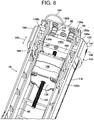
- FIG. 8 is a perspective view of the inside of spool 18, as taken along lines 8-8 in FIG. 7 and with 'lower' movable section 122b pivoted fully away from 'upper' movable section 122a in order to show additional internal components that may be included in the spool.
- spool 18 may include an internal framework 60, to which such internal components of the spool may be affixed, and a mounting plate 58, for attachment of the spool to upright bracket 54 (see, FIG. 3 ).
- Contact surface 118 may also be attached to framework 60 such that the contact surface is external to the framework.
- the upper section 122a is directly attached to framework 60, while the lower section 122b is indirectly attached via its attachment to upper section 122a at pivot member 120.
- machine 10 may include a positioning mechanism 132, which is structured and arranged to establish a position of the roll 28 on spool 18.
- the positioning mechanism 132 may generally comprise an engagement member 134 and an actuator 138.
- engagement member 134 is interposed between the roll 28 and support structure 12 (upright bracket 54 thereof) at the proximal end 52a of spool 18.
- Engagement member 134 is adapted to engage roll 28, and is structured and arranged to be movable relative to spool 18, as indicated by the two-way arrow 143 ( FIG. 8 ).
- Actuator 138 is structured and arranged to move engagement member 134 relative to the spool 18, e.g., bi-directionally as indicated by arrow 143. In this manner, the engagement member 134 and actuator 138 cooperatively establish the position of roll 28 on spool 18.
- spool 18 has an upward angle (relative to a horizontal plane) as the spool extends away from upright bracket 54.
- web roll 28 is gravitationally biased towards bracket 54 of support structure 12, as indicated by arrow 140, which represents the force vector of the gravitational bias that acts on roll 28 as mounted on angled spool 18.
- gravitational bias 140 results in roll 28 being forced against the engagement member (i.e., by gravity).
- Positioning mechanism 132 may further include a biasing element 136, e.g., a pair of biasing elements 136a, b as shown.
- Biasing elements 136a, b may be retained on or secured to mounting plate 58 as shown, e.g., via retainers 172 or the like, and may provide the function of biasing the engagement member 134 away from support structure 12/proximal end 52a of spool 18 and towards actuator 138/distal end 52b.
- biasing element(s) 136 may comprise any suitable resilient device, such as a spring (as illustrated), foam, gas-filled bladder, etc.
- Engagement member 134 may comprise a contact ring 144 and a guide bar 146, with the contact ring 144 being attached to the guide bar via fasteners (e.g., screws) 148.
- Contact ring 144 is the portion of engagement member 134 that engages, e.g., is in physical contact with, roll 28 ( FIG. 9B ), and may be coaxial with spool 18 and external to contact surface 118 thereof ( FIG. 8 ).
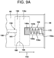
- Guide bar 146 may be structured and arranged to be linearly movable within a track 150, which may comprise a pair of opposing slots 150a, b in internal framework 60 (see, FIGS. 8 and 9A ).
- Guide bar 146 may comprise a pair of 'wing' sections 146a, b, which extend from a center section 146c, with wing sections 146a, b riding in respective slots 150a, b and center section 146c moving within the internal framework 60.
- track 150 thus constrains the movement of guide bar 146, and therefore of contact ring 144 attached thereto at wing sections 146a, b, to linear movement, i.e., in the form of translational movement along, and delimited by, slots 150a, b.
- the biasing element(s) 136 may include a first end 152a and a second end 152b (only biasing element 136a is visible in FIG. 9A ).
- the first end 152a exerts a force against support member 12, e.g., via mounting plate 58, which is attached to the support member.
- the second end 152b exerts an opposing force against guide bar 146, e.g., via direct contact therewith by second end 152b, and thereby biases the guide bar towards actuator 138 and distal end 52b of spool 18.
- the biasing force exerted by the second end 152b of the biasing elements 136 on guide bar 146 will constitute the above-described force 142 exerted by engagement member 134 against roll 28, in opposition to the gravitational force 140 of the roll against the engagement member.
- the inventors hereof have identified a problem associated with inflation and sealing machines.
- operators of such machines have been found to apply excessive force when loading new film rolls onto the spools of the machines, such that the roll makes a rather hard impact with the machine at the proximal end of the spool.
- Such excessive force can damage the machine, particularly when repeated over time. It has been determined that such damage will most often be manifested at actuator 138, particularly if the actuator is rigidly coupled to engagement member 134, such that most of the roll's force is transferred to the actuator during the loading process.
- the positioning mechanism 132 in accordance with the present invention provides a solution to the foregoing problem, whereby engagement member 134 and actuator 138 are configured such that the two components separate from one another when a force, e.g., as exerted by roll 28 on engagement member 134, exceeds a predetermined amount, which will generally occur when excessive force is applied during the roll-loading operation.
- a force e.g., as exerted by roll 28 on engagement member 134
- force 154 is the total of the force contributed by the operator (not shown) from loading roll 28 onto spool 18, plus gravitational force 140 when spool has an upward angle.
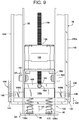
- FIG. 9 and 9C illustrate two steady-state conditions of positioning mechanism 132.
- FIG. 9 shows the 'pre-load' steady-state condition, i.e., prior to roll 28 being loaded onto spool 18.
- FIG. 9C illustrates the 'post-load' steady-state condition, i.e., after roll 28 has been loaded onto the spool and the force 154 associated with such loading has dissipated. In both of such steady-state conditions, it may be seen that actuator 138 is in contact with engagement member 134.
- FIG. 9B illustrates a transitory state of positioning mechanism 132, i.e., the loading of roll 28 onto spool 18, during which the actuator 138 and engagement member 134 separate from one another, thereby separating the roll-loading force 154 from actuator 138, which prevents force 154 from damaging the actuator.
- actuator 138 may comprise a motor 156, a drive screw 158 extending through the motor, and a contact member 160 attached to a distal end 161 of the drive screw, e.g., via set screw 163 as shown, with the distal end 161 of drive screw 158 being embedded inside of contact member 160 ( FIG. 9A ) and set screw 163 securing the distal end 161 therein.
- the motor 156 may be secured to internal frame 60 via mounting bracket 162 and fasteners 164 ( FIG. 9 ).
- motor 156 is preferably a precision-type motor, e.g., a rotary-to-linear motor capable of precise positioning, such as a stepper motor.
- precision motors such as motor 156 are relatively delicate and susceptible to damage from impact-type forces, e.g., as would be experienced from an excessive loading force being applied to roll 28.
- Such damage may be prevented by isolating the motor 156 from force 154, which may be achieved by configuring actuator 138 and engagement member 134 to separate from one another when a force, e.g., force 154 exerted by roll 28 on engagement member 134, exceeds a predetermined amount, e.g., biasing force 142.
- a force e.g., force 154 exerted by roll 28 on engagement member 134
- a predetermined amount e.g., biasing force 142.
- contact member 160 of actuator 138 and guide bar 146 of engagement member 134 have respective opposing surfaces 166, 168, which are shaped and relatively positioned to engage one another, i.e., to be in contact with one another, when positioning mechanism 132 is in a steady-state condition, i.e., either a pre-load ( FIG. 9 ) or post-load ( FIG. 9C ) condition, but also to disengage from one another to form a gap 170 therebetween when a roll 28 is being forcefully loaded onto spool 18 such that the positioning mechanism 132 is in a transitory condition ( FIG.
- FIGS. 9 and 9B i.e., with loading force 154 being applied to engagement member 134 such that the force 154 exceeds the opposing biasing force 142.
- surfaces 166, 168 are both flat, but other shapes are possible, e.g., various three-dimensional shapes that disengageably conform to one another, such as a concave-convex relationship.
- FIGS. 9 and 9B one can also see the movement of the entire engagement member 134 as a result of forceful roll loading, from its starting position in FIG. 9 to its displaced position along spool 18 towards mounting plate 58 in FIG. 9B due to loading force 154 being exerted on the engagement member, with the leading end of contact ring 144 extending beyond the corresponding end of section 122a of spool 18.
- biasing elements 136a, b may be included to provide the function of biasing the engagement member 134 away from support structure 12 (via mounting plate 58) and towards actuator 138.
- the biasing force of biasing elements 136 and overall configuration of positioning mechanism 132 are such that, when positioning mechanism 132 is in a steady-state condition, i.e., either pre-load ( FIG. 9 ) or post-load ( FIG. 9C ), the biasing elements 136 urge guide bar 146 into engagement, i.e., contact, with contact member 160, so that the respective surfaces 168, 166 thereof are pressed together.
- the amount of such biasing force 142 may thus define the predetermined minimum amount of force required to cause engagement member 134 to separate from actuator 138, and thereby produce gap 170, as shown in FIG. 9B .
- the force 154 exerted by roll 28 on engagement member 134 e.g., during loading, exceeds the biasing force 142 exerted by biasing elements 136 on the engagement member 134 against actuator 138 in the steady-state condition of positioning mechanism 132, actuator 138 and engagement member 134 separate from one another, thereby producing gap 170, as shown in FIG. 9B .
- the biasing elements 136 are in the form of springs, such that the biasing force 142 urging the guide bar 146 into engagement with contact member 160 in the pre-load and post-load steady-state conditions of the positioning mechanism 132 ( FIGS. 9 and 9C ) is a spring force.
- guide bar 146 and contact member 160 could be urged (disengageably held) together, e.g., via a mechanical or magnetic union.
- loading force 154 temporarily exceeds the opposing biasing force 142, which had been holding respective surfaces 166, 168 of contact member 160 and guide bar 146 together.
- roll 28 and engagement member 134 are thus accelerating towards mounting plate 58/support structure 12, as propelled by the loading force 154.
- Such acceleration will not damage actuator 138, however, given that the entirety of the force 154 has been de-coupled from the actuator 138 as a result of the separation of the engagement member 134 from the actuator 138 during the loading process.
- biasing element 136 may advantageously provide the function of controlling the movement of roll 28 when actuator 138 and engagement member 134 are separated from one another.
- the biasing force 142 generated by biasing element 136 will preferably be sufficient to absorb at least some, e.g., a substantial amount or all, of force 154, to thereby control the movement of the roll 28 during the transitory phase of separation of actuator 138 from engagement member 134, e.g., by decelerating/dampening the movement of the roll 28/engagement member 134 along force vector 154 in order to stabilize the roll and engagement member, and then move the roll and engagement member along force vector 142 to re-establish contact between the engagement member 134 and actuator 138.
- biasing element(s) 136 may restore machine 10 to a stable/operational run condition, with loading force 154 neutralized, by controlling the movement of roll 28 and returning positioning mechanism 132 to a steady-state position, i.e., the post-loading position as shown in FIG. 9C , in which the opposing surfaces 166, 168 of contact member 160 and guide bar 146 are once again held together by the biasing elements.
- FIG. 9C the roll-positioning operation of positioning mechanism 132 in a steady-state 'post-loading' condition will be described in further detail.
- the function of actuator 138 is to move engagement member 134 relative to spool 18 to thereby establish the position of roll 28 on the spool.
- the purpose of this is to ensure that the open longitudinal edge 30a and/or first ends 42a of transverse seals 38 of web 26 are optimally aligned relative to inflation system 22 and sealing device 24 for proper inflation and sealing of containers 32.
- actuator 138 is adapted to exert a force 174 against guide bar 146, which opposes the biasing force 142 exerted against the guide bar by the biasing element(s) 136.
- Actuator 138 may include any conventional drive means, including mechanical, electrical, and/or hydraulic drive means.
- actuator 138 is in the form of a linear actuator, including a motor 156, a drive screw 158 extending through the motor, and a contact member 160 attached to a distal end 161 of the drive screw, e.g., via set screw 163 as shown.
- the motor 156 is a rotation-to-translation type of motor, e.g., a stepper motor, and moves contact member 160 either towards or away from mounting plate 58/support structure 12, as indicated by double-headed arrow 143 ( FIG. 9A ), by generating clockwise or counter-clockwise rotation of drive screw 158.
- FIG. 9 shows a starting position for the positioning mechanism, i.e., with no roll on spool 18 and the actuator 138 and engagement member 134 in contact with one another due to the force 142 exerted by the biasing element 136.
- FIG. 9B shows a transitory condition for positioning mechanism 132 when loading force 154 is applied to the positioning mechanism from loading roll 28 onto spool 18, resulting in the separation of engagement member 134 from actuator 138.
- the position of the engagement member 134 changes from the starting position in FIG. 9 (moves towards mounting plate 58/support structure 12), but the position of the contact member 160 does not change, given that actuator 138 is not involved in the roll-loading process.
- the positioning mechanism 132 is in a state of readiness to adjust the position of roll 28 on spool 18.
- the positioning mechanism is in the process of making such an adjustment.
- the motor 156 is causing drive screw 158 to rotate in the direction of arrow 176, i.e., clockwise when viewed from behind the drive screw, which causes contact member 160 to apply force 174 against guide bar 146, such that contact member 160 and bar 146 both translate in the direction of the force vector 174 (towards mounting plate 58).
- the engagement member 134, biasing element 136, and actuator 138 synergistically cooperate to control both the loading and precision-placement of web roll 28 on spool 18.
- the former serves to protect motor 156 during roll loading, which maintains the latter ability of the positioning mechanism 132 to accurately control the position of web roll 28, and thereby properly align web 26 as it is conveyed through machine 10.
- Machine 10 may include a web tracking sensor 180, which is adapted to detect a transverse position of the inflatable web 26 with respect to inflation device 22 ( FIG. 6 ). Information from the web tracking sensor 180 may be used to control the operation of the positioning mechanism 132 in order to establish a desired position of roll 28 on spool 18, to thereby maintain the transverse position of web 26 within a predetermined range for optimum alignment with inflation system 22 and sealing device 24.
- a web tracking sensor 180 which is adapted to detect a transverse position of the inflatable web 26 with respect to inflation device 22 ( FIG. 6 ). Information from the web tracking sensor 180 may be used to control the operation of the positioning mechanism 132 in order to establish a desired position of roll 28 on spool 18, to thereby maintain the transverse position of web 26 within a predetermined range for optimum alignment with inflation system 22 and sealing device 24.
- the web tracking sensor 180 may be structured and arranged to detect the transverse position of the web 26 by detecting the position of the open longitudinal edge 30a and/or the position of printed marks on the web, e.g., via a mechanical contact sensor, an optical sensor, an ultrasonic sensor, etc.
- the tracking sensor 180 may be structured and arranged to detect the transverse seals 38, e.g., ends 42a or 42b thereof, such that a position of the transverse seals and/or the ends thereof indicates the transverse position of the web 26.
- the tracking sensor 180 is structured and arranged to detect first ends 42a of the transverse seals 38 via physical contact, such that the position of such first ends 42a indicates the transverse position of the inflatable web 26.
- the transverse seal ends 42a could be detected optically, i.e., via an optical sensor adapted to optically detect such seal ends.
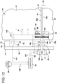
- Controller 94 may be in operative communication with both web tracking sensor 180, e.g., via input cable 182 ( FIG. 10 ), and with positioning mechanism 132, e.g., via output cable 184 ( FIGS. 5 , 8 and 11 ). Controller 94 may further be adapted, e.g., programmed, to receive input 182 from tracking sensor 180 and, based on that input, send output 184 to positioning mechanism 132 to adjust the position of roll 28 on spool 18 so as to maintain the transverse position of the inflatable web 26 within a predetermined range, e.g., so that the first ends 42a of transverse seals 38 are neither too close nor too far away from tracking sensor 180, and thus in good alignment with inflation system 22 and sealing device 24 for proper inflation and sealing.
- a predetermined range e.g., so that the first ends 42a of transverse seals 38 are neither too close nor too far away from tracking sensor 180, and thus in good alignment with inflation system 22 and sealing device 24 for proper inflation and sealing.
- tracking sensor 180 may be structured and arranged to be contacted by the first ends 42a of transverse seals 38.
- Tracking sensor 180 may thus comprise a contact sensor 186 and a detection sensor 188.
- Contact sensor 186 may be adapted to make physical contact with transverse seals 38 without impeding the movement of the web 26 along path 40.
- the contact sensor 186 may thus be movable, e.g., pivotable, translatable, bendable, etc., so that it moves upon contact with the transverse seals 38.
- contact sensor 186 is pivotally mounted inside of inflation nozzle 82 at pivot point 190, with a contact portion 191 extending from nozzle 82 so as to make contact with transverse seals 38 in sequential fashion as web 26 is conveyed past the inflation nozzle.
- Contact portion 191 thus resides inside of web 26 during inflation and sealing operations, i.e., between sheets 36a, b at the openings 34 of the containers 32.
- Contact sensor 186 may be biased against pivot stop 192 by coil spring 194, and is thus pivotally movable along arcuate arrow 196 ( FIG. 10 ).
- the movement of contact sensor 186 serves two functions. First, by moving upon contact with the seals 38, the contact sensor 186 allows the web 26 to continue its conveyance along path 40 ( FIG. 11 ). Preferably the movement is such that web conveyance continues without significant deviation due to the contact with the sensor. Secondly, the movement of the contact sensor 186 allows detection thereof by the detection sensor 188 in such a way that the transverse position of web 26 may be determined.
- the detection sensor 188 may, for example, be an optical sensor, including a light emitter 198 and a light receptor 199 ( FIG. 10A ), wherein light emitter 198 produces a beam of light, which is detect by light receptor 199, with emitter 198 and receptor 199 being spaced apart by gap 201.
- the contact sensor 186 and detection sensor 188 may be relatively arranged as shown in FIG. 10A , such that a tail portion 203 of contact sensor 186 is pivotally movable through gap 201 in detection sensor 188 as contact sensor 186 pivots about pivot point 190 through arc 196. Further, when the contact sensor 186 is in a neutral or resting position as shown in FIG. 10 , i.e., with spring 194 urging the sensor against pivot stop 192 due to no contact between contact portion 191 and transverse seals 38, the tail portion 203 is positioned inside of detection sensor 188 such that the tail portion is interposed between light emitter 198 and light receptor 199, whereby the tail portion 203 prevents the light beam produced by emitter 198 from reaching receptor 199.
- the tail portion 203 may be said to 'break' such light beam, such that no light is detected by receptor 199.
- the detection sensor 188 may thus be configured to send signal 182 to controller 94 only when, and for so long as, light is detected by receptor 199, whereby such signal 182 is indicative of both the fact and duration of contact between transverse seals 38 and contact portion 191 of contact sensor 186.
- the incidence and duration of light detection by receptor 199 i.e., based on the movement of contact sensor 186 due to contact with transverse seals 38, provides an indication of the transverse position of web 26.
- controller 94 sends a command output 184 to positioning mechanism 132, to move the roll 26 on spool 18 in the direction of arrow 178, i.e., towards mounting plate 58/support member 12 ( FIG. 9C ), which causes web 26, and thus ends 42a of transverse seals 38, to move closer to inflation system 22 and sealing device 24.
- controller 94 will send a command output 184 to positioning mechanism 132 to move the roll 26 in the opposite direction of arrow 178 ( FIG. 9C ), i.e., away from mounting plate 58/support member 12. This causes web 26, and thus ends 42a of transverse seals 38, to move away from contact sensor 186, inflation system 22, and sealing device 24.
- light may be detected by receptor 199 in intervals, indicating periodic contact between transverse seals 38 and contact sensor 186, but the duration of each period of light detection may be below the predetermined/pre-programmed value as described above.
- the web 26 is not so far away from inflation system 22 that the transverse seal ends 42a fail to make contact with contact sensor 186, but the web is still too far away for optimal alignment as indicated by the contact sensor 186 being held pivotally away from its neutral/beam-breaking position ( FIG. 10 ) for a duration of time that is less than desired for a proper spatial relationship between the contact sensor 186 and the transverse seal ends 42a.
- controller 94 sends a command output 184 to positioning mechanism 132, to move the roll 26 on spool 18 in the direction of arrow 178 ( FIG. 9C ), which causes web 26 to move closer to inflation system 22 and sealing device 24.
- the transverse position of inflatable web 26 will oscillate within a range, centered on the predetermined/pre-programmed value for the periodic duration of light detection by receptor 199, which corresponds to the selected spatial relationship between the contact sensor 186 and the transverse seal ends 42a.
- Such predetermined range may be as narrow or wide as desired, e.g., depending on how controller 94 is programmed to run the resultant feed-back control loop.
- various modes of control may be employed by controller 94, including proportional, derivative, integral, and combinations thereof, e.g., PID (proportional-integral-derivative) control, to achieve a desired predetermined range within which the transverse position of web 26 oscillates.
- Controller 94 may be in the form of a printed circuit assembly, e.g., a printed circuit board (PCB), and include a control unit, e.g., an electronic controller, such as a microcontroller, which stores pre-programmed operating codes; a programmable logic controller (PLC); a programmable automation controller (PAC); a personal computer (PC); or other such control device which is capable of receiving both operator commands and electronic, sensor-generated inputs, and carrying out predetermined, e.g., pre-programmed, operations based on such commands and inputs. Programming commands may be supplied to the controller 94 via control panel 90 or other type of operator interface, e.g., a wireless communication device.
- a control unit e.g., an electronic controller, such as a microcontroller, which stores pre-programmed operating codes; a programmable logic controller (PLC); a programmable automation controller (PAC); a personal computer (PC); or other such control device which is capable of receiving both operator commands and electronic
- Controller 94 may further be adapted, e.g., programmed, to determine the length of the containers 32 in any given inflatable web used with machine 10.
- the "length" is the longitudinal distance between a leading transverse seal 38a from a downstream pair of seals 38 and a following transverse seal 38b from an adjacent, upstream pair of seals 38, i.e., as measured parallel to the longitudinal edges 30a, b.
- the container length may be determined by controller 94 based on the rate at which web 26 is conveyed along path 40 by conveyance system 20, and upon the duration of the beam-break periods in web tracking sensor 180, in which the contact sensor 186 moves between transverse seals 38a, b within a container 32, and is thus in its neutral/noncontact position as shown in FIG. 10 .
- the rate of web conveyance is a value that is stored in, i.e., 'known by', controller 94, e.g., based on operator input via control panel 90 (and thus the basis of output 102 from controller 94 to conveyance system 20).
- the ability to determine container-length is advantageous, in that it allows the operations of selected sub-assemblies of machine 10 to be customized, based on the determined container-length in the web that is in use as the determination is made, in order to optimize the inflation and sealing of the containers in such web. For example, smaller containers often benefit from higher inflation rates vs. larger containers, and thus the speed of blower 80 may be varied based on the detected container-length.
- controller 94 may further be adapted, e.g., programmed, to cause machine 10 to discontinue operations in such a manner that inconsistent inflation of containers 32 is avoided or at least minimized as a result of a 'stop-then-restart' event.
- controller 94 may thus be configured and programmed to receive a stop command, e.g., from an operator via stop button 92 on control panel 90, and, based on input 182 from tracking sensor 180, send output 102 to web conveyance system 20 to stop conveying the inflatable web 26 such that the web stops at a predetermined location relative to a pair of the transverse seals 38 from adjacent containers, e.g., an un-inflated container 32 adjacent to an inflated container 50.
- a stop command e.g., from an operator via stop button 92 on control panel 90
- output 102 to web conveyance system 20 to stop conveying the inflatable web 26 such that the web stops at a predetermined location relative to a pair of the transverse seals 38 from adjacent containers, e.g., an un-inflated container 32 adjacent to an inflated container 50.
- predetermined location may be one in which a pair of transverse seals 38, designated as 38' for illustration purposes, from adjacent containers, e.g., an un-inflated container 32' and an inflated container 50', arrive at and stop in a straddling position relative to sealing device 24.
- a pair of transverse seals 38 designated as 38' for illustration purposes
- adjacent containers e.g., an un-inflated container 32' and an inflated container 50'
- the downstream container 50' associated with the downstream one 38b' of the pair of transverse seals 38' is fully inflated and sealed closed, with longitudinal seal 48 intersecting the transverse seal 38b' to seal closed the downstream/inflated container 50'.
- the upstream container 32' associated with the upstream one 38a' of the pair of transverse seals 38' is in position to be fully inflated by inflation system 22 and sealed closed by sealing device 24 upon receipt of a restart command, e.g., by the machine operator via start button 91 on control panel 90.
- transverse seal pair 38' is making contact with contact sensor 186, and this event is being 'reported' to controller 94 via input signal 182 from detection sensor 188.
- the controller 94 thus 'knows' the location of the transverse seal pair 38', as well as its rate of conveyance between tracking sensor 180 and sealing device 24.
- the controller 94 controls, e.g., slows, the rate of conveyance of web 26 via output signal 102/motor 68 such that the web stops just as transverse seal pair 38' has arrived at the straddling position shown in FIG. 12 .
- This feature advantageously ensures that the downstream container 50' is fully inflated and sealed closed, and that the upstream container 32' is in the correct position to be fully inflated and sealed closed upon a re-start of the machine, so that inconsistent inflation (e.g., under-inflation, over-inflation, or non-inflation) of the containers does not result from stop/re-start episodes.
- inconsistent inflation e.g., under-inflation, over-inflation, or non-inflation
- sealing device 24 may include a seal zone 200 and an isolation zone 202.
- Isolation zone 202 is upstream from seal zone 200 along the path of travel 40.
- the isolation zone 202 is structured and arranged to substantially isolate the seal zone 200 from irregularities in the web 26 as it is conveyed along path 40, thereby improving the consistency and quality of the longitudinal seal 48 produced by sealing device 24.
- sealing device 24 may comprise a pair of convergent members, e.g., a pair of counter-rotating rollers 62, 64, with sealing element 66 secured to at least one of the rollers, e.g., to roller 62 as shown.
- one convergent member may be rotary while one is stationary.
- the seal zone 200 is located at a point of convergence between the convergent rollers 62, 64, i.e., with nip 65 being located within seal zone 200, while the isolation zone 202 comprises a segment 204 of one of the convergent members, e.g., backing roller 64, against which web 26 is directed ( FIG. 13 ).
- Sealing device 24 may further comprise a deflection device 206, which is structured and arranged to intersect with path 40 in such a way that web 26 is deflected and directed against segment 204 as the web is conveyed along path 40, to thereby produce isolation zone 202.
- a deflection device 206 which is structured and arranged to intersect with path 40 in such a way that web 26 is deflected and directed against segment 204 as the web is conveyed along path 40, to thereby produce isolation zone 202.
- isolation zone 202 is angularly displaced from seal zone 200, and comprises a fixed segment 204, i.e., a fixed arc, of backing roller 64, through which the roller rotates as it comes into contact with web 26, due to the deflection thereof by deflection device 206.
- roller 64 maintains contact with web 26 through seal zone 200, and then leaves contact with the web after rotating through the seal zone.
- the deflection device 206 may comprise a guide bar as shown, or any suitable device capable of deflecting the web onto backing roller 64, such that isolation zone extends from the deflection device 206 to seal zone 200.
- sealing device 24 may further include one or more web guides 208 ( FIG. 14 ) or 208' ( FIG. 15 ).
- the web guides 208, 208' are structured and arranged to direct at least a portion of the web 26 away from seal zone 200 as the web is conveyed along path 40, in order to prevent the web from becoming entangled in the rollers 62, 64 as a result of the formation of longitudinal seal 48 by sealing device 24.
- FIG. 14 One embodiment is illustrated in FIG. 14 , wherein web guides 208, e.g., a pair of such web guides 208a, b, one for sealing roller 62 and one for backing roller 64, respectively, direct web 26 away from seal zone 200 in a downstream direction along path 40.
- web guides 208 e.g., a pair of such web guides 208a, b, one for sealing roller 62 and one for backing roller 64, respectively, direct web 26 away from seal zone 200 in a downstream direction along path 40.
- at least a portion 210a, b of each respective web guide 208a, b is downstream from seal zone 200 along path 40, so that the web 26 is directed in a substantially linear path, e.g., a tangential, non-rotary path, which does not follow the rotation of either of the rollers 62, 64 away from seal zone 200.
- one or both of the web guides 208a, b may include a lateral segment 211 to direct web 26 away from seal zone 200 in a lateral direction, i.e., laterally away from sealing roller 62. As illustrated, lateral segment 211 extends from web guide 208a in a lateral direction relative to path 40. Although a pair of web guides 208a, b is illustrated, only one of the web guides, i.e., either 208a or 208b, may be employed if desired.
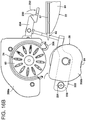
- FIG. 15 An alternative embodiment is shown in FIG. 15 , wherein web guides 208', e.g., a pair of such web guides 208a' and 208b', one on each opposing side of sealing roller 62, direct web 26 away from seal zone 200 in a radial direction, i.e., radially away from sealing roller 62.
- web guides 208' e.g., a pair of such web guides 208a' and 208b', one on each opposing side of sealing roller 62, direct web 26 away from seal zone 200 in a radial direction, i.e., radially away from sealing roller 62.
- at least a portion 210a' and 210b' of each respective web guide 208a' and 208b' is radially spaced from seal zone 200 relative to sealing roller 62, such that web 26 is directed radially away from the seal zone 200, e.g., with downward angles relative to path 40.
- web guides 208a' and 208b' are illustrated, only one of the web guides, i.e., either 208a' or 208b', may be employed if desired. Further, the web guides 208 and 208' may be used together, i.e., in combination, or independently (as illustrated).
- FIG. 5 illustrates one mode of operation, wherein machine 10 may include surface supports, i.e., 'feet', 212, which are adapted to allow the machine to be mounted on a table 214 during operations.
- a receptacle 216 may be placed adjacent to table 214 as shown, such that completed containers 50 may be directed from machine 10 and into the receptacle, e.g., in order to generate a readily-available supply of the inflated/sealed containers for subsequent use.
- Machine 10 may thus further include a detector 218 adapted to detect the presence of a predetermined quantity of the inflated containers 50 in receptacle 216, e.g., a height of the inflated containers in the receptacle.
- Detector 218 may be in operative communication with controller 94, e.g., via input cable 220, and the controller may be adapted, e.g., programmed, to perform at least one of:
- Web conveyance system 20 may comprise a pair of rotary members, e.g., rollers 62, 64, wherein at least one of the rotary members is mounted on a pivot mechanism 222 with an upstream actuator 224 and a downstream pivot point 226.
- the pivot mechanism 222 is movable between:
- backing roller 64 is carried on pivot frame 228, which is pivotally mounted on support structure 12 at pivot point 226.
- Pivot mechanism 222 is a four-bar link mechanism, and includes a pivotally-movable handle member 230. When grasped and moved in the direction of arrow 232 ( FIG. 16B ), the handle member 230 of pivot mechanism 222 allows the backing roller 64 to be moved out of contact with sealing roller 62 to facilitate the placement of web 26 between such rollers, e.g., upon placement of a new roll 28 on spool 18 and subsequent 'threading' of the new web 26 through the above-described components of machine 10 along path 40.
- the handle member 230 is moved in the opposing direction of arrow 232 in order to return the pivot mechanism 222 to its conveyance position as shown in FIG. 16A , so that the rollers 62, 64 are in compressive contact with opposing sides of web 26 and ready to begin withdrawing the web from the new roll and advancing the web along path 40.
- FIG. 14 One embodiment is illustrated in FIG. 14 , wherein web guides 208, e.g., a pair of such web guides 208a, b, one for sealing roller 62 and one for backing roller 64, respectively, direct web 26 away from seal zone 200 in a downstream direction along path 40.
- web guides 208 e.g., a pair of such web guides 208a, b, one for sealing roller 62 and one for backing roller 64, respectively, direct web 26 away from seal zone 200 in a downstream direction along path 40.
- at least a portion 210a, b of each respective web guide 208a, b is downstream from seal zone 200 along path 40, so that the web 26 is directed in a substantially linear path, e.g., a tangential, non-rotary path, which does not follow the rotation of either of the rollers 62, 64 away from seal zone 200.
- one or both of the web guides 208a, b may include a lateral segment 211 to direct web 26 away from seal zone 200 in a lateral direction, i.e., laterally away from sealing roller 62. As illustrated, lateral segment 211 extends from web guide 208a in a lateral direction relative to path 40. Although a pair of web guides 208a, b is illustrated, only one of the web guides, i.e., either 208a or 208b, may be employed if desired.
- FIG. 15 An alternative embodiment is shown in FIG. 15 , wherein web guides 208', e.g., a pair of such web guides 208a' and 208b', one on each opposing side of sealing roller 62, direct web 26 away from seal zone 200 in a radial direction, i.e., radially away from sealing roller 62.
- web guides 208' e.g., a pair of such web guides 208a' and 208b', one on each opposing side of sealing roller 62, direct web 26 away from seal zone 200 in a radial direction, i.e., radially away from sealing roller 62.
- at least a portion 210a' and 210b' of each respective web guide 208a' and 208b' is radially spaced from seal zone 200 relative to sealing roller 62, such that web 26 is directed radially away from the seal zone 200, e.g., with downward angles relative to path 40.
- web guides 208a' and 208b' are illustrated, only one of the web guides, i.e., either 208a' or 208b', may be employed if desired. Further, the web guides 208 and 208' may be used together, i.e., in combination, or independently (as illustrated).
- FIG. 5 illustrates one mode of operation, wherein machine 10 may include surface supports, i.e., 'feet', 212, which are adapted to allow the machine to be mounted on a table 214 during operations.
- a receptacle 216 may be placed adjacent to table 214 as shown, such that completed containers 50 may be directed from machine 10 and into the receptacle, e.g., in order to generate a readily-available supply of the inflated/sealed containers for subsequent use.
- Machine 10 may thus further include a detector 218 adapted to detect the presence of a predetermined quantity of the inflated containers 50 in receptacle 216, e.g., a height of the inflated containers in the receptacle.
- Detector 218 may be in operative communication with controller 94, e.g., via input cable 220, and the controller may be adapted, e.g., programmed, to perform at least one of:
- Web conveyance system 20 may comprise a pair of rotary members, e.g., rollers 62, 64, wherein at least one of the rotary members is mounted on a pivot mechanism 222 with an upstream actuator 224 and a downstream pivot point 226.
- the pivot mechanism 222 is movable between:
- backing roller 64 is carried on pivot frame 228, which is pivotally mounted on support structure 12 at pivot point 226.
- Pivot mechanism 222 is a four-bar link mechanism, and includes a pivotally-movable handle member 230. When grasped and moved in the direction of arrow 232 ( FIG. 16B ), the handle member 230 of pivot mechanism 222 allows the backing roller 64 to be moved out of contact with sealing roller 62 to facilitate the placement of web 26 between such rollers, e.g., upon placement of a new roll 28 on spool 18 and subsequent 'threading' of the new web 26 through the above-described components of machine 10 along path 40.
- the handle member 230 is moved in the opposing direction of arrow 232 in order to return the pivot mechanism 222 to its conveyance position as shown in FIG. 16A , so that the rollers 62, 64 are in compressive contact with opposing sides of web 26 and ready to begin withdrawing the web from the new roll and advancing the web along path 40.
Landscapes
- Engineering & Computer Science (AREA)
- Mechanical Engineering (AREA)
- Containers And Plastic Fillers For Packaging (AREA)
- Making Paper Articles (AREA)
- Replacement Of Web Rolls (AREA)
- Registering, Tensioning, Guiding Webs, And Rollers Therefor (AREA)
- Air Bags (AREA)
- Treatment Of Fiber Materials (AREA)
Claims (14)
- Machine (10) pour gonfler et sceller une bande gonflable (26) comprenant des bords longitudinaux opposés (30a, 30b) et une paire de feuilles (36a, 36b) scellées l'une à l'autre par des joints transversaux (38a, 38b) formant une série de récipients gonflables (32) entre des paires des joints transversaux, chacun des récipients (32) étant capable de contenir à l'intérieur de celui-ci une quantité de gaz et comportant une ouverture (34) pour recevoir un tel gaz, ladite machine comprenant :a. une structure de support (12) ;b. une bobine (18) attachée à ladite structure de support pour supporter, de manière à pouvoir tourner, un rouleau de la bande gonflable, ladite bobine (18) comportant une extrémité proximale (52a) à laquelle ladite bobine (18) est attachée à ladite structure de support (12) ;c. un mécanisme de positionnement (132) structuré et agencé pour établir une position du rouleau (28) sur ladite bobine (18), ledit mécanisme de positionnement (132) comprenant :1) un organe de mise en prise (134) interposé entre le rouleau (28) et ladite structure de support (12) à ladite extrémité proximale (52a) de ladite bobine (18), ledit organe de mise en prise étant apte à se mettre en prise avec le rouleau (28) et à se déplacer par rapport à ladite bobine (18), et2) un actionneur (138) structuré et agencé pour déplacer ledit organe de mise en prise (134) afin d'établir de ce fait ladite position du rouleau (28) sur ladite bobine (18), dans laquelle ledit actionneur (138) et ledit organe de mise en prise (134) sont configurés pour se séparer l'un de l'autre lorsqu'une force exercée sur ledit organe de mise en prise (134) dépasse une quantité prédéterminée ;d. un système de transport de bande (20) pour transporter la bande gonflable le long d'une voie (40) de déplacement sensiblement parallèle aux bords longitudinaux (30a, 30b) de la bande gonflable (26) ;e. un système de gonflage (22) structuré et agencé pour diriger un gaz dans les ouvertures (34) des récipients (32) au fur et à mesure que la bande est avancée le long de la voie (40), en gonflant de ce fait les récipients (32) ;f. un capteur de suivi de bande (180) apte à détecter une position transversale de la bande gonflable par rapport au dit système de gonflage (22) ;g. un dispositif de scellement (24) pour la fermeture étanche des ouvertures (34) des récipients (32) après le gonflage de ceux-ci par le système de gonflage (22) ; eth. un organe de commande (94) en communication opérationnelle avec ledit capteur de suivi de bande (180) et avec ledit mécanisme de positionnement (132), ledit organe de commande étant apte à recevoir une entrée dudit capteur de suivi (180) et, sur la base de ladite entrée, envoyer une sortie au dit mécanisme de positionnement (132) pour ajuster ladite position du rouleau (28) sur ladite bobine (18) de manière à maintenir ladite position transversale de la bande gonflable (26) à l'intérieur d'une plage prédéterminée.
- Machine selon la revendication 1, dans laquelle ledit actionneur (138) et ledit organe de mise en prise (134) comportent des surfaces opposées respectives (166, 168) qui sont formées et positionnées l'une par rapport à l'autre pour :a) se mettre en prise l'une avec l'autre lorsque ledit actionneur (138) déplace ledit organe de mise en prise (134), etb) se mettre hors prise l'une de l'autre lorsque ladite force dépasse ladite quantité prédéterminée.
- Machine selon la revendication 2, dans laquellea) ledit actionneur (138) comprend un organe de contact (166) comportant l'une (166) desdites surfaces opposées ;b) ledit organe de mise en prise (14) comprend un anneau de contact (144) et une barre de guidage (145a, 146b, 146c), ladite barre de guidage comportant l'autre (168) desdites surfaces opposées ;c) ledit anneau de contact (144) est attaché à ladite barre de guidage (145a, 146b, 146c) ; etd) ladite barre de guidage (145a, 146b, 146c) est structurée et agencée pour pouvoir se déplacer linéairement à l'intérieur d'un rail (150a, 150b).
- Machine selon la revendication 3, dans laquelle ledit mécanisme de positionnement (132) comprend en outre un élément de polarisation (136a, 136b) pour polariser ledit organe de mise en prise (134) vers ledit actionneur (138) de sorte que, lorsqu'un rouleau (28) est chargé sur ladite bobine (18) avec une force sur ledit organe de mise en prise (134) qui dépasse ladite quantité prédéterminée pour amener ledit actionneur (138) et ledit organe de mise en prise (134) à se séparer l'un de l'autre, ledit élément de polarisation (136a, 136b) commande un mouvement du rouleau (28) au cours de ladite séparation.
- Machine selon la revendication 4, dans laquelle
ledit élément de polarisation (136a, 136b) force ladite barre de guidage (145a, 146b, 146c) à se mettre en prise avec ledit organe de contact (160) avec une force de polarisation ; et
ladite quantité de force prédéterminée au-dessus de laquelle ledit actionneur (138) et ledit organe de mise en prise (134) se séparent l'un de l'autre comprend ladite force de polarisation. - Machine selon la revendication 5, dans laquelle ledit actionneur (138) est apte à exercer une force contre ladite barre de guidage (145a, 146b, 146c) qui s'oppose à ladite force de polarisation.
- Machine selon la revendication 1, dans laquelle ledit capteur de suivi (180) est structuré et agencé pour détecter des extrémités (42a) des joints transversaux (38a, 38b) de sorte qu'une position de celles-ci indique ladite position transversale de la bande gonflable (26).
- Machine selon la revendication 1, dans laquelle ledit organe de commande (94) est en outre apte à :a) recevoir une commande d'arrêt ; etb) sur la base de ladite entrée provenant dudit capteur de suivi (180), envoyer une sortie au dit système de transport de bande (20) pour arrêter le transport de la bande gonflable (26) de sorte que la bande s'arrête à un emplacement prédéterminé par rapport à une paire des joints transversaux (38a, 38b) à partir de récipients adjacents (32).
- Machine selon la revendication 1, dans laquellea) ledit dispositif de scellement (24) comprend une zone de joint (200) et une zone d'isolation (202) ;b) ladite zone d'isolation (202) est en amont de ladite zone de joint (200) le long de ladite voie de déplacement (40) ; etc) ladite zone d'isolation (202) est structurée et agencée pour isoler sensiblement ladite zone de joint (200) d'irrégularités dans la bande au fur et à mesure de son transport le long de ladite voie (40).
- Machine selon la revendication 9, dans laquellea) ledit dispositif de scellement (24) comprend une paire d'organes convergents (62, 64) ;b) ladite zone de joint (200) est située à un point de convergence entre lesdits organes convergents (62, 64) ; etc) ladite zone d'isolation (202) comprend un segment de l'un desdits organes convergents (62, 64) contre lequel ladite bande (26) est dirigée.
- Machine selon la revendication 10, dans laquelle ledit dispositif de scellement (24) comprend en outre un dispositif de déviation (206), qui est structuré et agencé pour être en intersection avec ladite voie (40) de telle manière que la bande soit dirigée contre ledit segment au fur et à mesure que la bande est transportée le long de ladite voie, afin de produire de ce fait ladite zone d'isolation (202).
- Machine selon la revendication 1, dans laquellea) ledit dispositif de scellement (24) comprend une zone de joint (200) et un ou plusieurs guides de bande (208a, 208b) ; etb) lesdits guides de bande (208a, 208b) sont structurés et agencés pour diriger au moins une portion de la bande (26) à l'écart de ladite zone de joint (200) au fur et à mesure que la bande est transportée le long de ladite voie (40).
- Machine selon la revendication 1, dans laquellea) le rouleau (28) comprend un mandrin (114) présentant une périphérie intérieure ; etb) ladite bobine (18) comprend une surface de contact (118) et est structurée et agencée de sorte que ladite surface de contact (118) exerce une force polarisée vers l'extérieur contre la périphérie intérieure du mandrin (114).
- Machine selon la revendication 1, comprenant en outre un détecteur (218) apte à détecter la présence d'une quantité prédéterminée de récipients gonflés dans un réceptacle (216), ledit détecteur (218) étant en communication opérationnelle avec ledit organe de commande (94) et ledit organe de commande étant apte à effectuer au moins l'un de :a) l'arrêt du fonctionnement de ladite machine une fois que ladite quantité prédéterminée est détectée ; etb) le démarrage du fonctionnement de ladite machine si ladite quantité prédéterminée n'est pas détectée.
Applications Claiming Priority (2)
| Application Number | Priority Date | Filing Date | Title |
|---|---|---|---|
| US14/029,956 US10286617B2 (en) | 2013-09-18 | 2013-09-18 | Machine for inflating and sealing an inflatable web |
| PCT/US2014/055613 WO2015041976A1 (fr) | 2013-09-18 | 2014-09-15 | Machine pour gonfler et sceller une âme gonflable |
Publications (2)
| Publication Number | Publication Date |
|---|---|
| EP3046820A1 EP3046820A1 (fr) | 2016-07-27 |
| EP3046820B1 true EP3046820B1 (fr) | 2017-08-23 |
Family
ID=51703384
Family Applications (1)
| Application Number | Title | Priority Date | Filing Date |
|---|---|---|---|
| EP14784136.5A Active EP3046820B1 (fr) | 2013-09-18 | 2014-09-15 | Machine pour gonfler et sceller une bande gonflable |
Country Status (11)
| Country | Link |
|---|---|
| US (1) | US10286617B2 (fr) |
| EP (1) | EP3046820B1 (fr) |
| JP (1) | JP6457540B2 (fr) |
| CN (1) | CN105705397B (fr) |
| AU (1) | AU2014321497B2 (fr) |
| BR (1) | BR112016005415B1 (fr) |
| CA (1) | CA2922963C (fr) |
| ES (1) | ES2649152T3 (fr) |
| MX (1) | MX2016003348A (fr) |
| NZ (1) | NZ717427A (fr) |
| WO (1) | WO2015041976A1 (fr) |
Families Citing this family (39)
| Publication number | Priority date | Publication date | Assignee | Title |
|---|---|---|---|---|
| US10864664B2 (en) | 2011-08-31 | 2020-12-15 | Pregis Intellipack Llc | Foam-in-bag device with bag-status indicator |
| US10850906B2 (en) * | 2015-03-04 | 2020-12-01 | Storopack, Inc. | Air cushion machine and method |
| JP6466751B2 (ja) * | 2015-03-19 | 2019-02-06 | 株式会社イシダ | フィルムロール支持装置 |
| JP6896379B2 (ja) | 2015-07-02 | 2021-06-30 | シールド・エアー・コーポレイション(ユーエス) | 膨張クッションを提供するシステム |
| WO2017023164A1 (fr) * | 2015-08-03 | 2017-02-09 | Ideepack Holding B.V. | Dispositif et procédé de fabrication de coussins à gaz à partir de matériau de film préconçu |
| US20170036795A1 (en) * | 2015-08-05 | 2017-02-09 | Tung-Lung Chiang | Sealing Structure of Air-Pocket Film Machine |
| US10946606B2 (en) * | 2015-10-20 | 2021-03-16 | Sealed Air Corporation (Us) | Machine for manufacturing inflated cushioning products |
| ES2785664T3 (es) * | 2016-01-29 | 2020-10-07 | Sealed Air Corp | Sistema para producir bandas hinchadas |
| WO2017172834A1 (fr) * | 2016-03-28 | 2017-10-05 | Pregis Innovative Packaging Llc | Galet fou |
| USD832903S1 (en) * | 2016-05-12 | 2018-11-06 | LOGIN Corporate Investment GmbH & Co. KG | Packaging machine |
| USD842352S1 (en) * | 2016-05-16 | 2019-03-05 | Hangzhou Bing Jia Technology Co., Ltd. | Bag or sack filling machine |
| WO2018048745A1 (fr) | 2016-09-06 | 2018-03-15 | Sealed Air Corporation (Us) | Bande d'amortissement gonflable |
| EP3529067B1 (fr) * | 2016-10-24 | 2021-02-24 | Sealed Air Corporation (US) | Poches gonflables à distorsions extérieures réduites |
| US20190248094A1 (en) * | 2016-10-26 | 2019-08-15 | Sealed Air Corporation (Us) | Film inflation systems and components thereof |
| WO2018112286A1 (fr) | 2016-12-15 | 2018-06-21 | Sealed Air Corporation (Us) | Procédé d'emballage |
| US10894652B2 (en) | 2016-12-15 | 2021-01-19 | Sealed Air Corporation (Us) | Inflatable cushioning web |
| WO2018136375A1 (fr) | 2017-01-17 | 2018-07-26 | Sealed Air Corporation (Us) | Système et procédé de détachement de coussins d'emballage |
| WO2018236687A1 (fr) | 2017-06-19 | 2018-12-27 | Sealed Air Corporation (Us) | Emballage rembourré de protection d'objets |
| DE102017114340A1 (de) * | 2017-06-28 | 2019-01-03 | Storopack Hans Reichenecker Gmbh | Vorrichtung zum Bereitstellen von Polstermaterial für Verpackungszwecke |
| WO2019010073A1 (fr) | 2017-07-06 | 2019-01-10 | Sealed Air Corporation (Us) | Emballage avec matelassage gonflé et insert élastique |
| EP3533598A1 (fr) * | 2018-03-01 | 2019-09-04 | Storopack Hans Reichenecker GmbH | Machine et système de production de matériau de rembourrage |
| EP3830013B1 (fr) | 2018-07-30 | 2023-06-28 | Sealed Air Corporation (US) | Mandrin pour maintenir et aligner des rouleaux d'alimentation de film |
| US11542086B2 (en) * | 2018-08-06 | 2023-01-03 | Better Packages, Inc. | Packaging apparatus for film inflation and method thereof |
| WO2020072727A1 (fr) * | 2018-10-04 | 2020-04-09 | Automated Packaging Systems, Llc | Machine de gonflage de coussin d'air |
| EP3880562A4 (fr) | 2018-11-14 | 2022-08-17 | Sealed Air Corporation (US) | Bande cellulaire gonflable à multiples panneaux gonflables |
| EP3898423A1 (fr) | 2018-12-21 | 2021-10-27 | Sealed Air Corporation (US) | Station d'emballage automatisée et système d'emballage d'objets |
| WO2020227587A1 (fr) | 2019-05-09 | 2020-11-12 | Sealed Air Corporation (Us) | Matériaux en bande gonflables et leurs structures d'étanchéité |
| WO2020227586A1 (fr) | 2019-05-09 | 2020-11-12 | Sealed Air Corporation (Us) | Correction de trajet de matériaux en bande gonflables |
| WO2020227584A1 (fr) | 2019-05-09 | 2020-11-12 | Sealed Air Corporation (Us) | Matériaux en bande gonflables et rails pour leur guidage |
| WO2020227591A1 (fr) | 2019-05-09 | 2020-11-12 | Sealed Air Corporation (Us) | Guides pour parties pliées de bandes gonflables |
| EP3966027A1 (fr) | 2019-05-09 | 2022-03-16 | Sealed Air Corporation (US) | Buses de gonflage pour matériaux en bande à canal fermé |
| WO2020227590A1 (fr) | 2019-05-09 | 2020-11-12 | Sealed Air Corporation (Us) | Matériau cellulaire pneumatique gonflable à zones de pliage |
| US11845600B2 (en) | 2019-08-28 | 2023-12-19 | Sealed Air Corporation (Us) | Inflatable packaging material with non-continuous longitudinal channels |
| CN114555482A (zh) | 2019-10-22 | 2022-05-27 | 希悦尔公司 | 可充胀幅材沿充胀喷嘴的被动跟踪 |
| WO2021081028A1 (fr) | 2019-10-22 | 2021-04-29 | Sealed Air Corporation (Us) | Dispositifs de gonflage pour bandes gonflables avec dispositifs de déplacement de gaz en série |
| CN115835955A (zh) | 2020-07-13 | 2023-03-21 | 希悦尔公司 | 具有宽背衬辊的辊密封机器 |
| CN116438057A (zh) | 2020-10-08 | 2023-07-14 | 希悦尔公司 | 缓冲式可封闭袋的幅材 |
| CN112722417B (zh) * | 2020-12-31 | 2022-09-16 | 安徽百特新材料科技有限公司 | 一种真空绝热板表层防涨袋的包装方法 |
| CN116588440A (zh) * | 2023-06-12 | 2023-08-15 | 杭州丙甲科技有限公司 | 一种热封传动机构及气垫机 |
Family Cites Families (48)
| Publication number | Priority date | Publication date | Assignee | Title |
|---|---|---|---|---|
| US3596428A (en) | 1968-10-07 | 1971-08-03 | American Maize Prod Co | Packaging process and apparatus |
| US3546433A (en) | 1969-02-25 | 1970-12-08 | Electronic Control Systems Inc | Roll heater device |
| US3660189A (en) | 1969-04-28 | 1972-05-02 | Constantine T Troy | Closed cell structure and methods and apparatus for its manufacture |
| US3703430A (en) | 1971-03-12 | 1972-11-21 | Joseph L Rich | Apparatus for fabricating plastic cushioning and insulating material |
| US3735551A (en) | 1971-12-20 | 1973-05-29 | Pratt Manufactoring Corp | Apparatus for and method of packaging with gas flushing |
| US3817803A (en) | 1972-06-19 | 1974-06-18 | Fmc Corp | Method of making a cellular cushioning structure |
| US3908881A (en) * | 1973-03-21 | 1975-09-30 | Gary D Mccann | Centering sensor and controller |
| US3868285A (en) | 1973-07-18 | 1975-02-25 | Constantine T Troy | Methods and apparatus for the manufacture of cellular cushioning materials |
| GB1524967A (en) * | 1974-11-13 | 1978-09-13 | Sissons A J | Roll-handling equipment |
| US4096306A (en) | 1975-12-24 | 1978-06-20 | Minnesota Mining And Manufacturing Company | Strip material used in forming air inflated cushioning material |
| US4017351A (en) | 1975-12-24 | 1977-04-12 | Minnesota Mining And Manufacturing Company | System and device for inflating and sealing air inflated cushioning material |
| US4141517A (en) | 1978-03-22 | 1979-02-27 | Martin Automatic, Inc. | Apparatus for adjusting the lateral position of a rolled web |
| US4384442A (en) | 1978-04-27 | 1983-05-24 | Pendleton John M | Apparatus for making cushioning packaging material |
| US4847126A (en) | 1982-07-01 | 1989-07-11 | Hiroshi Yamashiro | Elongated plastic material |
| US5087318A (en) * | 1988-12-02 | 1992-02-11 | Minnesota Mining And Manufacturing Company | Web-aligning apparatus |
| DE3922802A1 (de) | 1989-07-11 | 1991-01-24 | Becker Rolf | Aufblasbarer folienbeutel, insbesondere fuer verpackungszwecke und verfahren zu dessen herstellung |
| US5187917A (en) | 1990-10-29 | 1993-02-23 | Cvp Systems, Inc. | Automatic packaging apparatus and method and flexible pouch therefor |
| DE59106094D1 (de) | 1991-05-03 | 1995-08-31 | Michel Chappuis | Polsterungselement zum Verpacken von Körpern und Vorrichtung zum Herstellen eines Polsterungselementes. |
| US5376219A (en) | 1991-09-26 | 1994-12-27 | Sealed Air Corporation | High speed apparatus for forming foam cushions for packaging purposes |
| US5216868A (en) | 1992-01-28 | 1993-06-08 | Andrew K. Cooper | Packaging product and machine for making same |
| EP0679588B1 (fr) | 1993-11-05 | 1998-03-04 | Shinwa Corporation | Gonfleur pour enveloppe a gaz a compartiments a gaz independants successifs |
| GB9401913D0 (en) | 1994-02-01 | 1994-03-30 | Watkins David L | Bag sealing apparatus |
| US5824392A (en) | 1994-03-24 | 1998-10-20 | Idemitsu Petrochemical Co., Ltd. | Method of producing an air cushion and an apparatus for the same |
| US5552003A (en) | 1994-10-04 | 1996-09-03 | Hoover; Gregory A. | Method for producing inflated dunnage |
| US5660662A (en) | 1995-04-25 | 1997-08-26 | Testone Enterprises, Inc. | Method and apparatus for forming filled cushions, and filled cushions |
| US5664738A (en) * | 1996-05-17 | 1997-09-09 | Fife; Robert L. | Pneumatic web guide |
| US5942076A (en) | 1997-03-13 | 1999-08-24 | Sealed Air Corporation | Inflatable cushion forming machine |
| IL123041A (en) | 1998-01-25 | 2001-05-20 | Nova Tek Technologies Ltd | Apparatus and method for making pouches |
| US5938098A (en) * | 1998-11-17 | 1999-08-17 | Fife; Robert L. | Servo valve |
| US6209286B1 (en) | 1999-03-09 | 2001-04-03 | Novus Packaging Corporation | Machine and method for manufacturing a continuous production of pneumatically filled inflatable packaging pillows |
| US7536837B2 (en) | 1999-03-09 | 2009-05-26 | Free-Flow Packaging International, Inc. | Apparatus for inflating and sealing pillows in packaging cushions |
| US6423166B1 (en) | 1999-04-22 | 2002-07-23 | Ebrahim Simhaee | Method of making collapsed air cell dunnage suitable for inflation |
| US6460313B1 (en) | 1999-05-24 | 2002-10-08 | Andrew Cooper | Packaging filler product and machine for producing same |
| US6582800B2 (en) | 2000-01-20 | 2003-06-24 | Free-Flow Packaging International, Inc. | Method for making pneumatically filled packing cushions |
| CA2423513C (fr) | 2000-08-04 | 2007-05-22 | West Virginia University | Instruments et detection informatises destines a l'apprentissage de l'examen physique |
| US6410119B1 (en) | 2000-11-21 | 2002-06-25 | Free-Flow Packaging International, Inc. | Inflatable, cushioning, bubble wrap product having multiple, interconnected, bubble structures |
| US6651406B2 (en) | 2001-02-13 | 2003-11-25 | Sealed Air Corporation (Us) | Apparatus and method for forming inflated containers |
| US6635145B2 (en) | 2001-06-11 | 2003-10-21 | Andrew Cooper | Packaging filler product |
| AU2005203038A1 (en) * | 2004-07-15 | 2006-02-02 | Sealed Air Corporation (Us) | High-speed apparatus and method for forming inflated chambers |
| US7225599B2 (en) | 2005-04-05 | 2007-06-05 | Sealed Air Corporation | Apparatus and method for forming inflated articles |
| US8695311B2 (en) | 2006-04-26 | 2014-04-15 | Free-Flow Packaging International, Inc. | Apparatus for inflating and sealing packing cushions employing film recognition controller |
| US8567159B2 (en) | 2007-04-12 | 2013-10-29 | Sealed Air Corporation (Us) | Apparatus and method for making inflated articles |
| JP4199823B1 (ja) * | 2008-04-08 | 2008-12-24 | ▲邦▼男 佐藤 | エアー緩衝材製造装置 |
| US20090308965A1 (en) * | 2008-06-17 | 2009-12-17 | Sealed Air Corporation (Us) | Machine, method, and system for severing a web |
| US8402719B2 (en) * | 2008-09-03 | 2013-03-26 | Free-Flowing Packaging International, Inc. | Method and apparatus for inflating and sealing packing cushions with rotary sealing mechanism |
| US7950433B2 (en) * | 2009-02-12 | 2011-05-31 | Sealed Air Corporation (Us) | Machine for inflating and sealing an inflatable web |
| US8991141B2 (en) | 2009-04-06 | 2015-03-31 | Sealed Air Corporation (Us) | Machine for inflating and sealing an inflatable structure |
| US8554363B2 (en) | 2010-09-21 | 2013-10-08 | Sealed Air Corporation | Apparatus configured to dispense a plurality of connected inflatable structures and associated system and method |
-
2013
- 2013-09-18 US US14/029,956 patent/US10286617B2/en active Active
-
2014
- 2014-09-15 EP EP14784136.5A patent/EP3046820B1/fr active Active
- 2014-09-15 ES ES14784136.5T patent/ES2649152T3/es active Active
- 2014-09-15 BR BR112016005415-6A patent/BR112016005415B1/pt active IP Right Grant
- 2014-09-15 JP JP2016543942A patent/JP6457540B2/ja active Active
- 2014-09-15 CA CA2922963A patent/CA2922963C/fr active Active
- 2014-09-15 AU AU2014321497A patent/AU2014321497B2/en active Active
- 2014-09-15 WO PCT/US2014/055613 patent/WO2015041976A1/fr active Application Filing
- 2014-09-15 NZ NZ71742714A patent/NZ717427A/en unknown
- 2014-09-15 MX MX2016003348A patent/MX2016003348A/es active IP Right Grant
- 2014-09-15 CN CN201480063030.5A patent/CN105705397B/zh active Active
Non-Patent Citations (1)
| Title |
|---|
| None * |
Also Published As
| Publication number | Publication date |
|---|---|
| AU2014321497A1 (en) | 2016-03-17 |
| JP6457540B2 (ja) | 2019-01-23 |
| MX2016003348A (es) | 2016-06-06 |
| US20150075114A1 (en) | 2015-03-19 |
| BR112016005415B1 (pt) | 2023-01-24 |
| BR112016005415A2 (fr) | 2017-08-01 |
| AU2014321497B2 (en) | 2017-09-21 |
| ES2649152T3 (es) | 2018-01-10 |
| CA2922963C (fr) | 2018-07-24 |
| CN105705397B (zh) | 2018-02-23 |
| CA2922963A1 (fr) | 2015-03-26 |
| EP3046820A1 (fr) | 2016-07-27 |
| CN105705397A (zh) | 2016-06-22 |
| JP2016532587A (ja) | 2016-10-20 |
| US10286617B2 (en) | 2019-05-14 |
| WO2015041976A1 (fr) | 2015-03-26 |
| NZ717427A (en) | 2019-11-29 |
Similar Documents
| Publication | Publication Date | Title |
|---|---|---|
| EP3046820B1 (fr) | Machine pour gonfler et sceller une bande gonflable | |
| EP3408070B1 (fr) | Système de production de bandes gonflées | |
| US7950433B2 (en) | Machine for inflating and sealing an inflatable web | |
| CA2934067C (fr) | Systeme servant a fournir des coussins gonfles | |
| US11772353B2 (en) | Recipe controlled process for making packaging materials | |
| WO2017053285A1 (fr) | Ensemble de support réglable et de machine de fardage | |
| NZ721521B2 (en) | System for providing inflated cushions | |
| NZ721521A (en) | System for providing inflated cushions | |
| CA2654675A1 (fr) | Appareil de gonflement et de scellage de toile gonflable | |
| US20230256699A1 (en) | Roller sealing machines having wide backing rollers | |
| BR102016015278A2 (pt) | System for supply of inflated pads |
Legal Events
| Date | Code | Title | Description |
|---|---|---|---|
| PUAI | Public reference made under article 153(3) epc to a published international application that has entered the european phase |
Free format text: ORIGINAL CODE: 0009012 |
|
| 17P | Request for examination filed |
Effective date: 20160226 |
|
| AK | Designated contracting states |
Kind code of ref document: A1 Designated state(s): AL AT BE BG CH CY CZ DE DK EE ES FI FR GB GR HR HU IE IS IT LI LT LU LV MC MK MT NL NO PL PT RO RS SE SI SK SM TR |
|
| AX | Request for extension of the european patent |
Extension state: BA ME |
|
| DAX | Request for extension of the european patent (deleted) | ||
| GRAP | Despatch of communication of intention to grant a patent |
Free format text: ORIGINAL CODE: EPIDOSNIGR1 |
|
| INTG | Intention to grant announced |
Effective date: 20170329 |
|
| GRAS | Grant fee paid |
Free format text: ORIGINAL CODE: EPIDOSNIGR3 |
|
| GRAA | (expected) grant |
Free format text: ORIGINAL CODE: 0009210 |
|
| AK | Designated contracting states |
Kind code of ref document: B1 Designated state(s): AL AT BE BG CH CY CZ DE DK EE ES FI FR GB GR HR HU IE IS IT LI LT LU LV MC MK MT NL NO PL PT RO RS SE SI SK SM TR |
|
| RAP1 | Party data changed (applicant data changed or rights of an application transferred) |
Owner name: SEALED AIR CORPORATION (US) |
|
| REG | Reference to a national code |
Ref country code: GB Ref legal event code: FG4D |
|
| REG | Reference to a national code |
Ref country code: CH Ref legal event code: EP |
|
| REG | Reference to a national code |
Ref country code: AT Ref legal event code: REF Ref document number: 920981 Country of ref document: AT Kind code of ref document: T Effective date: 20170915 |
|
| REG | Reference to a national code |
Ref country code: IE Ref legal event code: FG4D |
|
| REG | Reference to a national code |
Ref country code: FR Ref legal event code: PLFP Year of fee payment: 4 |
|
| REG | Reference to a national code |
Ref country code: DE Ref legal event code: R096 Ref document number: 602014013599 Country of ref document: DE |
|
| REG | Reference to a national code |
Ref country code: NL Ref legal event code: MP Effective date: 20170823 |
|
| REG | Reference to a national code |
Ref country code: ES Ref legal event code: FG2A Ref document number: 2649152 Country of ref document: ES Kind code of ref document: T3 Effective date: 20180110 Ref country code: LT Ref legal event code: MG4D |
|
| REG | Reference to a national code |
Ref country code: AT Ref legal event code: MK05 Ref document number: 920981 Country of ref document: AT Kind code of ref document: T Effective date: 20170823 |
|
| PG25 | Lapsed in a contracting state [announced via postgrant information from national office to epo] |
Ref country code: LT Free format text: LAPSE BECAUSE OF FAILURE TO SUBMIT A TRANSLATION OF THE DESCRIPTION OR TO PAY THE FEE WITHIN THE PRESCRIBED TIME-LIMIT Effective date: 20170823 Ref country code: FI Free format text: LAPSE BECAUSE OF FAILURE TO SUBMIT A TRANSLATION OF THE DESCRIPTION OR TO PAY THE FEE WITHIN THE PRESCRIBED TIME-LIMIT Effective date: 20170823 Ref country code: NO Free format text: LAPSE BECAUSE OF FAILURE TO SUBMIT A TRANSLATION OF THE DESCRIPTION OR TO PAY THE FEE WITHIN THE PRESCRIBED TIME-LIMIT Effective date: 20171123 Ref country code: NL Free format text: LAPSE BECAUSE OF FAILURE TO SUBMIT A TRANSLATION OF THE DESCRIPTION OR TO PAY THE FEE WITHIN THE PRESCRIBED TIME-LIMIT Effective date: 20170823 Ref country code: SE Free format text: LAPSE BECAUSE OF FAILURE TO SUBMIT A TRANSLATION OF THE DESCRIPTION OR TO PAY THE FEE WITHIN THE PRESCRIBED TIME-LIMIT Effective date: 20170823 Ref country code: AT Free format text: LAPSE BECAUSE OF FAILURE TO SUBMIT A TRANSLATION OF THE DESCRIPTION OR TO PAY THE FEE WITHIN THE PRESCRIBED TIME-LIMIT Effective date: 20170823 Ref country code: HR Free format text: LAPSE BECAUSE OF FAILURE TO SUBMIT A TRANSLATION OF THE DESCRIPTION OR TO PAY THE FEE WITHIN THE PRESCRIBED TIME-LIMIT Effective date: 20170823 |
|
| PG25 | Lapsed in a contracting state [announced via postgrant information from national office to epo] |
Ref country code: RS Free format text: LAPSE BECAUSE OF FAILURE TO SUBMIT A TRANSLATION OF THE DESCRIPTION OR TO PAY THE FEE WITHIN THE PRESCRIBED TIME-LIMIT Effective date: 20170823 Ref country code: PL Free format text: LAPSE BECAUSE OF FAILURE TO SUBMIT A TRANSLATION OF THE DESCRIPTION OR TO PAY THE FEE WITHIN THE PRESCRIBED TIME-LIMIT Effective date: 20170823 Ref country code: LV Free format text: LAPSE BECAUSE OF FAILURE TO SUBMIT A TRANSLATION OF THE DESCRIPTION OR TO PAY THE FEE WITHIN THE PRESCRIBED TIME-LIMIT Effective date: 20170823 Ref country code: BG Free format text: LAPSE BECAUSE OF FAILURE TO SUBMIT A TRANSLATION OF THE DESCRIPTION OR TO PAY THE FEE WITHIN THE PRESCRIBED TIME-LIMIT Effective date: 20171123 Ref country code: GR Free format text: LAPSE BECAUSE OF FAILURE TO SUBMIT A TRANSLATION OF THE DESCRIPTION OR TO PAY THE FEE WITHIN THE PRESCRIBED TIME-LIMIT Effective date: 20171124 Ref country code: IS Free format text: LAPSE BECAUSE OF FAILURE TO SUBMIT A TRANSLATION OF THE DESCRIPTION OR TO PAY THE FEE WITHIN THE PRESCRIBED TIME-LIMIT Effective date: 20171223 |
|
| PG25 | Lapsed in a contracting state [announced via postgrant information from national office to epo] |
Ref country code: DK Free format text: LAPSE BECAUSE OF FAILURE TO SUBMIT A TRANSLATION OF THE DESCRIPTION OR TO PAY THE FEE WITHIN THE PRESCRIBED TIME-LIMIT Effective date: 20170823 Ref country code: RO Free format text: LAPSE BECAUSE OF FAILURE TO SUBMIT A TRANSLATION OF THE DESCRIPTION OR TO PAY THE FEE WITHIN THE PRESCRIBED TIME-LIMIT Effective date: 20170823 Ref country code: CZ Free format text: LAPSE BECAUSE OF FAILURE TO SUBMIT A TRANSLATION OF THE DESCRIPTION OR TO PAY THE FEE WITHIN THE PRESCRIBED TIME-LIMIT Effective date: 20170823 |
|
| REG | Reference to a national code |
Ref country code: CH Ref legal event code: PL |
|
| REG | Reference to a national code |
Ref country code: DE Ref legal event code: R097 Ref document number: 602014013599 Country of ref document: DE |
|
| PG25 | Lapsed in a contracting state [announced via postgrant information from national office to epo] |
Ref country code: SM Free format text: LAPSE BECAUSE OF FAILURE TO SUBMIT A TRANSLATION OF THE DESCRIPTION OR TO PAY THE FEE WITHIN THE PRESCRIBED TIME-LIMIT Effective date: 20170823 Ref country code: MC Free format text: LAPSE BECAUSE OF FAILURE TO SUBMIT A TRANSLATION OF THE DESCRIPTION OR TO PAY THE FEE WITHIN THE PRESCRIBED TIME-LIMIT Effective date: 20170823 Ref country code: SK Free format text: LAPSE BECAUSE OF FAILURE TO SUBMIT A TRANSLATION OF THE DESCRIPTION OR TO PAY THE FEE WITHIN THE PRESCRIBED TIME-LIMIT Effective date: 20170823 Ref country code: EE Free format text: LAPSE BECAUSE OF FAILURE TO SUBMIT A TRANSLATION OF THE DESCRIPTION OR TO PAY THE FEE WITHIN THE PRESCRIBED TIME-LIMIT Effective date: 20170823 |
|
| REG | Reference to a national code |
Ref country code: IE Ref legal event code: MM4A |
|
| REG | Reference to a national code |
Ref country code: BE Ref legal event code: MM Effective date: 20170930 |
|
| PG25 | Lapsed in a contracting state [announced via postgrant information from national office to epo] |
Ref country code: LU Free format text: LAPSE BECAUSE OF NON-PAYMENT OF DUE FEES Effective date: 20170915 |
|
| PLBE | No opposition filed within time limit |
Free format text: ORIGINAL CODE: 0009261 |
|
| STAA | Information on the status of an ep patent application or granted ep patent |
Free format text: STATUS: NO OPPOSITION FILED WITHIN TIME LIMIT |
|
| PG25 | Lapsed in a contracting state [announced via postgrant information from national office to epo] |
Ref country code: IE Free format text: LAPSE BECAUSE OF NON-PAYMENT OF DUE FEES Effective date: 20170915 Ref country code: LI Free format text: LAPSE BECAUSE OF NON-PAYMENT OF DUE FEES Effective date: 20170930 Ref country code: CH Free format text: LAPSE BECAUSE OF NON-PAYMENT OF DUE FEES Effective date: 20170930 |
|
| 26N | No opposition filed |
Effective date: 20180524 |
|
| PG25 | Lapsed in a contracting state [announced via postgrant information from national office to epo] |
Ref country code: SI Free format text: LAPSE BECAUSE OF FAILURE TO SUBMIT A TRANSLATION OF THE DESCRIPTION OR TO PAY THE FEE WITHIN THE PRESCRIBED TIME-LIMIT Effective date: 20170823 Ref country code: BE Free format text: LAPSE BECAUSE OF NON-PAYMENT OF DUE FEES Effective date: 20170930 |
|
| REG | Reference to a national code |
Ref country code: FR Ref legal event code: PLFP Year of fee payment: 5 |
|
| PG25 | Lapsed in a contracting state [announced via postgrant information from national office to epo] |
Ref country code: MT Free format text: LAPSE BECAUSE OF NON-PAYMENT OF DUE FEES Effective date: 20170915 |
|
| PG25 | Lapsed in a contracting state [announced via postgrant information from national office to epo] |
Ref country code: HU Free format text: LAPSE BECAUSE OF FAILURE TO SUBMIT A TRANSLATION OF THE DESCRIPTION OR TO PAY THE FEE WITHIN THE PRESCRIBED TIME-LIMIT; INVALID AB INITIO Effective date: 20140915 |
|
| PG25 | Lapsed in a contracting state [announced via postgrant information from national office to epo] |
Ref country code: CY Free format text: LAPSE BECAUSE OF FAILURE TO SUBMIT A TRANSLATION OF THE DESCRIPTION OR TO PAY THE FEE WITHIN THE PRESCRIBED TIME-LIMIT Effective date: 20170823 |
|
| PG25 | Lapsed in a contracting state [announced via postgrant information from national office to epo] |
Ref country code: MK Free format text: LAPSE BECAUSE OF FAILURE TO SUBMIT A TRANSLATION OF THE DESCRIPTION OR TO PAY THE FEE WITHIN THE PRESCRIBED TIME-LIMIT Effective date: 20170823 |
|
| PG25 | Lapsed in a contracting state [announced via postgrant information from national office to epo] |
Ref country code: TR Free format text: LAPSE BECAUSE OF FAILURE TO SUBMIT A TRANSLATION OF THE DESCRIPTION OR TO PAY THE FEE WITHIN THE PRESCRIBED TIME-LIMIT Effective date: 20170823 |
|
| PG25 | Lapsed in a contracting state [announced via postgrant information from national office to epo] |
Ref country code: PT Free format text: LAPSE BECAUSE OF FAILURE TO SUBMIT A TRANSLATION OF THE DESCRIPTION OR TO PAY THE FEE WITHIN THE PRESCRIBED TIME-LIMIT Effective date: 20170823 |
|
| PG25 | Lapsed in a contracting state [announced via postgrant information from national office to epo] |
Ref country code: AL Free format text: LAPSE BECAUSE OF FAILURE TO SUBMIT A TRANSLATION OF THE DESCRIPTION OR TO PAY THE FEE WITHIN THE PRESCRIBED TIME-LIMIT Effective date: 20170823 |
|
| P01 | Opt-out of the competence of the unified patent court (upc) registered |
Effective date: 20230425 |
|
| PGFP | Annual fee paid to national office [announced via postgrant information from national office to epo] |
Ref country code: IT Payment date: 20230920 Year of fee payment: 10 Ref country code: GB Payment date: 20230926 Year of fee payment: 10 |
|
| PGFP | Annual fee paid to national office [announced via postgrant information from national office to epo] |
Ref country code: FR Payment date: 20230926 Year of fee payment: 10 Ref country code: DE Payment date: 20230928 Year of fee payment: 10 |
|
| PGFP | Annual fee paid to national office [announced via postgrant information from national office to epo] |
Ref country code: ES Payment date: 20231018 Year of fee payment: 10 |