EP3046733B1 - Dispositif d'entraînement avec accumulateur pneumatique - Google Patents
Dispositif d'entraînement avec accumulateur pneumatique Download PDFInfo
- Publication number
- EP3046733B1 EP3046733B1 EP14766121.9A EP14766121A EP3046733B1 EP 3046733 B1 EP3046733 B1 EP 3046733B1 EP 14766121 A EP14766121 A EP 14766121A EP 3046733 B1 EP3046733 B1 EP 3046733B1
- Authority
- EP
- European Patent Office
- Prior art keywords
- energy
- piston
- gas
- driving
- driving device
- Prior art date
- Legal status (The legal status is an assumption and is not a legal conclusion. Google has not performed a legal analysis and makes no representation as to the accuracy of the status listed.)
- Active
Links
- 239000012528 membrane Substances 0.000 claims description 14
- 238000004146 energy storage Methods 0.000 claims description 10
- 239000007787 solid Substances 0.000 claims description 4
- 230000000977 initiatory effect Effects 0.000 claims 1
- 239000007789 gas Substances 0.000 description 33
- 230000005540 biological transmission Effects 0.000 description 9
- 239000003570 air Substances 0.000 description 7
- 239000002184 metal Substances 0.000 description 3
- CURLTUGMZLYLDI-UHFFFAOYSA-N Carbon dioxide Chemical compound O=C=O CURLTUGMZLYLDI-UHFFFAOYSA-N 0.000 description 2
- 230000001133 acceleration Effects 0.000 description 2
- 239000012080 ambient air Substances 0.000 description 2
- 238000010586 diagram Methods 0.000 description 2
- 229920001971 elastomer Polymers 0.000 description 2
- 239000000806 elastomer Substances 0.000 description 2
- 239000000463 material Substances 0.000 description 2
- IJGRMHOSHXDMSA-UHFFFAOYSA-N Atomic nitrogen Chemical compound N#N IJGRMHOSHXDMSA-UHFFFAOYSA-N 0.000 description 1
- 239000001569 carbon dioxide Substances 0.000 description 1
- 229910002092 carbon dioxide Inorganic materials 0.000 description 1
- 238000006243 chemical reaction Methods 0.000 description 1
- 238000002485 combustion reaction Methods 0.000 description 1
- 230000006835 compression Effects 0.000 description 1
- 238000007906 compression Methods 0.000 description 1
- 238000013016 damping Methods 0.000 description 1
- 230000001419 dependent effect Effects 0.000 description 1
- 230000000694 effects Effects 0.000 description 1
- 239000002737 fuel gas Substances 0.000 description 1
- 238000000265 homogenisation Methods 0.000 description 1
- 238000009434 installation Methods 0.000 description 1
- JCXJVPUVTGWSNB-UHFFFAOYSA-N nitrogen dioxide Inorganic materials O=[N]=O JCXJVPUVTGWSNB-UHFFFAOYSA-N 0.000 description 1
- 239000003380 propellant Substances 0.000 description 1
- 230000001960 triggered effect Effects 0.000 description 1
Images

Classifications
-
- B—PERFORMING OPERATIONS; TRANSPORTING
- B25—HAND TOOLS; PORTABLE POWER-DRIVEN TOOLS; MANIPULATORS
- B25C—HAND-HELD NAILING OR STAPLING TOOLS; MANUALLY OPERATED PORTABLE STAPLING TOOLS
- B25C1/00—Hand-held nailing tools; Nail feeding devices
- B25C1/04—Hand-held nailing tools; Nail feeding devices operated by fluid pressure, e.g. by air pressure
- B25C1/047—Mechanical details
-
- B—PERFORMING OPERATIONS; TRANSPORTING
- B25—HAND TOOLS; PORTABLE POWER-DRIVEN TOOLS; MANIPULATORS
- B25C—HAND-HELD NAILING OR STAPLING TOOLS; MANUALLY OPERATED PORTABLE STAPLING TOOLS
- B25C1/00—Hand-held nailing tools; Nail feeding devices
- B25C1/04—Hand-held nailing tools; Nail feeding devices operated by fluid pressure, e.g. by air pressure
-
- B—PERFORMING OPERATIONS; TRANSPORTING
- B25—HAND TOOLS; PORTABLE POWER-DRIVEN TOOLS; MANIPULATORS
- B25C—HAND-HELD NAILING OR STAPLING TOOLS; MANUALLY OPERATED PORTABLE STAPLING TOOLS
- B25C1/00—Hand-held nailing tools; Nail feeding devices
- B25C1/06—Hand-held nailing tools; Nail feeding devices operated by electric power
-
- B—PERFORMING OPERATIONS; TRANSPORTING
- B25—HAND TOOLS; PORTABLE POWER-DRIVEN TOOLS; MANIPULATORS
- B25C—HAND-HELD NAILING OR STAPLING TOOLS; MANUALLY OPERATED PORTABLE STAPLING TOOLS
- B25C1/00—Hand-held nailing tools; Nail feeding devices
- B25C1/08—Hand-held nailing tools; Nail feeding devices operated by combustion pressure
Definitions
- the invention relates to a tacker according to the preamble of claim 1.
- a mechanical energy store means any component that can absorb and temporarily store mechanical energy.
- it may be a gas spring or preferably an elastically deformable Act solid.
- an elastically deformable solid are inter alia coil springs, coil springs, disc springs, torsion bars, elastic bands of an elastomer or the like to understand.
- each retractable nail, bolt or screw understood.
- the propellant gas in preferred embodiments is air, in particular ambient air. But it can also be gases such as air, nitrogen or carbon dioxide from a pressure reservoir or to reaction gases from a combustion.
- the energy store comprises an elastically deformable solid.
- Such energy storage generate little heat loss and can be well combined with respect to their spring constants for combination with the gas space.
- the energy store comprises a rubber-elastic membrane, wherein the membrane forms the further wall portion.
- a rubber-elastic membrane By widening the gas space volume while the membrane is expanded against its elastic restoring force and thus used as energy storage.
- the diaphragm initially contracts and, at least in a first movement section of the piston, brings about a homogenization of the gas pressure acting on the piston.
- the energy store comprises a piston as a further wall section and a spring, wherein the piston is supported against the spring.
- the advantages of mechanical springs, in particular metal springs can be used with regard to their small installation space and the high possible spring constants.
- the piston is movable in the same direction of movement as the piston of the energy transmission element. This allows a Particularly simple design of the remaining housing wall of the gas space, for example as a simple or stepped cylinder.
- the drive gas is conveyed into the gas space by means of a compressor, which is preferably integrated in the housing.
- a compressor which is preferably integrated in the housing.
- the compressor preferably comprises an electric drive, wherein the electric drive is particularly preferably driven by an accumulator as an energy source. This allows a wireless device, while the high energy densities of modern batteries can be used at the same time.
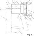
- the drive-in device according to the invention Fig. 1 comprises a hand-held housing 1, in which a power transmission element 2 is accommodated with a drive device 3.
- the drive device comprises a gas space 7, which can be filled by means of a compressor 9 with a drive gas at a defined pressure.
- the energy transmission element 2 comprises a drive element 2a in the form of a substantially cylindrical plunger. In a front region of the tacker, a damping stop 4 for the energy transmission element 2 is arranged.
- Fasteners are received in a magazine 5.
- a feed mechanism (not shown)
- a fastener is in each case transported into a chamber, from where it is accelerated by the action of the drive member 2a and driven through a mouth part into a workpiece (not shown).
- the driving member 2 a is connected to a piston 2 b of the power transmission element 2, wherein the piston 2 b is guided in a cylinder 6.
- the gas space 7 can be filled with a drive gas, in the present case compressed air, under an overpressure relative to the external pressure.
- the gas space 7 is enclosed by a rigid wall section which also comprises a pressure-side part of the cylinder 6, the movable piston 2b as the first variable wall section and a rubber-elastic membrane 8 as the second variable wall section.
- the elastomeric membrane 8 expands depending on the pressure or degree of filling of the gas space 7 against an inherent material tension. As a result, it forms a mechanical energy storage in which energy is stored in addition to the energy in the pressurized gas. To avoid overstretching of the membrane, it is surrounded by a rigid housing wall 1a, against which it can rest at maximum expansion.
- the compressor 9 is driven by an electric drive, for example a rotating electric motor in conjunction with an oscillating mechanism.
- the power source of the electric drive is an accumulator 10 provided on the housing 1.
- ambient air is pumped into the gas space 7 by means of the compressor until a defined pressure is reached. This may in particular be a maximum pressure of the compressor.
- the membrane 8 from a relaxed state (dashed line in FIG Fig. 1 ) into an expanded and tensioned state (solid line in FIG Fig. 1 ).
- the device can be triggered if necessary, which is done by an electromechanical release of the previously held energy transfer element 2.
- the piston 2b is accelerated forward by the applied pressure. Since the membrane initially relaxes, the gas pressure is only slightly reduced, at least in a first movement section.
- Fig. 2 shows by means of a diagram the relationship between pressure and volume in the gas space 7.
- the effect of the elastic membrane is a good constancy of the gas pressure, as long as the membrane is in an at least partially tensioned state.
- the energy transmission element 2 After driving in the fastening means, the energy transmission element 2 is reset by a return spring (not shown) in the starting position and locked. Finally, the refilling of the gas space 7 takes place through the compressor 9.
- a further piston 11 is provided instead of the rubber-elastic membrane 8, which is movably guided in a rear, shaped as a cylinder 12 portion of the gas space 7 and so forms a to the piston 2b further variable wall portion of the gas space 7.
- the piston 11 is guided gas-tight against the cylinder 12, wherein the cylinder 12 on which the outside of the piston 11 is freely connected to the atmosphere.
- the piston 11 is also supported on a plurality of springs 13, which in the present case are coil springs made of metal. In embodiments not shown are torsion, spiral or leaf springs made of metal or Kunsstoff or an elastomer.
- springs 13 shown schematically, which act depending on the position of the piston as tension springs or as compression springs.
- the springs 13 can be arranged inside and / or outside the gas space 7. By an at least partial arrangement within the gas space can be saved particularly effective space.
- the function of the driving device according to the second embodiment is analogous to the first embodiment with the difference that the springs instead of the membrane material form the further mechanical energy storage. It moves the piston 11 increases in pressure in the gas space against the force of the springs 13, so that the gas space increases as in the first embodiment.
Landscapes
- Engineering & Computer Science (AREA)
- Mechanical Engineering (AREA)
- Physics & Mathematics (AREA)
- Fluid Mechanics (AREA)
- Portable Nailing Machines And Staplers (AREA)
- Compressors, Vaccum Pumps And Other Relevant Systems (AREA)
- Reciprocating Pumps (AREA)
Claims (8)
- Dispositif d'enfoncement comportant :un boîtier tenu à la main (1) ayant un élément de transmission d'énergie (2) reçu dans celui-ci pour transmettre de l'énergie à un élément de fixation devant être enfoncé, etun dispositif d'entraînement (3) pour transporter l'élément de transmission d'énergie (2),dans lequel le dispositif d'entraînement (3) comporte un accumulateur d'énergie avec un compartiment de gaz qui peut être rempli avec un gaz d'entraînement sous une surpression définie,dans lequel la surpression dans le compartiment de gaz (7) est présente sous forme d'énergie d'entraînement stockée avant un déclenchement d'une opération d'enfoncement, etdans lequel un piston (2b) de l'élément de transmission d'énergie (2) forme une partie de paroi variable du compartiment de gaz (7),dans lequel le compartiment de gaz (7) comporte au moins une partie de paroi variable supplémentaire (8, 11) pour faire varier le volume du compartiment, caractérisé en ce qu'un remplissage du compartiment de gaz avec le gaz d'entraînement engendre un mouvement de la partie de paroi variable (8, 11) qui augmente le volume du compartiment et charge un accumulateur d'énergie mécanique (8, 13).
- Dispositif d'enfoncement selon la revendication 1, caractérisé en ce que l'accumulateur d'énergie (8, 13) comporte un corps solide élastiquement déformable.
- Dispositif d'enfoncement selon la revendication 2, caractérisé en ce que l'accumulateur d'énergie comporte une membrane élastique comme du caoutchouc (8), dans lequel la membrane forme la partie de paroi supplémentaire.
- Dispositif d'enfoncement selon la revendication 2, caractérisé en ce que l'accumulateur d'énergie comporte un piston (11) en tant que partie de paroi supplémentaire et un ressort (13), dans lequel le piston (11) est supporté contre le ressort (13).
- Dispositif d'enfoncement selon la revendication 4, caractérisé en ce que le piston (11) peut être déplacé dans la même direction de déplacement que le piston (2b) de l'élément de transmission d'énergie (2).
- Dispositif d'enfoncement selon l'une des revendications précédentes, caractérisé en ce que le gaz d'entraînement est transporté dans le compartiment de gaz au moyen d'un compresseur (9) en particulier intégré dans le boîtier (1).
- Dispositif d'enfoncement selon la revendication 6, caractérisé en ce que le compresseur (9) comporte une commande électrique.
- Dispositif d'enfoncement selon la revendication 7, caractérisé en ce que la commande électrique est entraînée au moins facultativement par un accumulateur (10) faisant office de source d'énergie.
Priority Applications (1)
| Application Number | Priority Date | Filing Date | Title |
|---|---|---|---|
| EP14766121.9A EP3046733B1 (fr) | 2013-09-19 | 2014-09-03 | Dispositif d'entraînement avec accumulateur pneumatique |
Applications Claiming Priority (3)
| Application Number | Priority Date | Filing Date | Title |
|---|---|---|---|
| EP13185168.5A EP2851157A1 (fr) | 2013-09-19 | 2013-09-19 | Dispositif d'entraînement avec accumulateur pneumatique |
| EP14766121.9A EP3046733B1 (fr) | 2013-09-19 | 2014-09-03 | Dispositif d'entraînement avec accumulateur pneumatique |
| PCT/EP2014/068693 WO2015039865A1 (fr) | 2013-09-19 | 2014-09-03 | Dispositif d'enfoncement à accumulateur pneumatique |
Publications (2)
| Publication Number | Publication Date |
|---|---|
| EP3046733A1 EP3046733A1 (fr) | 2016-07-27 |
| EP3046733B1 true EP3046733B1 (fr) | 2018-01-10 |
Family
ID=49230566
Family Applications (2)
| Application Number | Title | Priority Date | Filing Date |
|---|---|---|---|
| EP13185168.5A Withdrawn EP2851157A1 (fr) | 2013-09-19 | 2013-09-19 | Dispositif d'entraînement avec accumulateur pneumatique |
| EP14766121.9A Active EP3046733B1 (fr) | 2013-09-19 | 2014-09-03 | Dispositif d'entraînement avec accumulateur pneumatique |
Family Applications Before (1)
| Application Number | Title | Priority Date | Filing Date |
|---|---|---|---|
| EP13185168.5A Withdrawn EP2851157A1 (fr) | 2013-09-19 | 2013-09-19 | Dispositif d'entraînement avec accumulateur pneumatique |
Country Status (5)
| Country | Link |
|---|---|
| US (1) | US10259110B2 (fr) |
| EP (2) | EP2851157A1 (fr) |
| CN (1) | CN105555484B (fr) |
| TW (1) | TW201520010A (fr) |
| WO (1) | WO2015039865A1 (fr) |
Families Citing this family (11)
| Publication number | Priority date | Publication date | Assignee | Title |
|---|---|---|---|---|
| EP2886260A1 (fr) * | 2013-12-19 | 2015-06-24 | HILTI Aktiengesellschaft | Appareil d'enfoncement |
| EP2923800A1 (fr) * | 2014-03-28 | 2015-09-30 | HILTI Aktiengesellschaft | Cloueur à poudre |
| WO2016174994A1 (fr) * | 2015-04-30 | 2016-11-03 | 日立工機株式会社 | Outil pour clouer |
| WO2017045972A1 (fr) * | 2015-09-14 | 2017-03-23 | Hilti Aktiengesellschaft | Cloueuse fonctionnant au moyen d'un gaz combustible et dotée d'un organe d'alimentation |
| US11110577B2 (en) | 2017-11-16 | 2021-09-07 | Milwaukee Electric Tool Corporation | Pneumatic fastener driver |
| JP7247476B2 (ja) * | 2018-05-31 | 2023-03-29 | 工機ホールディングス株式会社 | 打込機 |
| DE102018117519A1 (de) * | 2018-07-19 | 2020-01-23 | Prebena Wilfried Bornemann Gmbh & Co. Kg | Druckluftbetriebene Austreibvorrichtung |
| FR3086569B1 (fr) | 2018-10-01 | 2020-12-18 | Illinois Tool Works | Outil de fixation a gaz et son procede de fonctionnement |
| US11819989B2 (en) | 2020-07-07 | 2023-11-21 | Techtronic Cordless Gp | Powered fastener driver |
| CA3167425A1 (fr) | 2021-07-16 | 2023-01-16 | Techtronic Cordless Gp | Pose-attaches electrique |
| EP4201597A1 (fr) * | 2021-12-23 | 2023-06-28 | Hilti Aktiengesellschaft | Dispositif et procédé d'enfoncement |
Family Cites Families (30)
| Publication number | Priority date | Publication date | Assignee | Title |
|---|---|---|---|---|
| US4200213A (en) * | 1977-08-10 | 1980-04-29 | Agence Nationale De Valorisation De La Recherche (Anvar) | Percussion apparatus |
| US4175314A (en) * | 1978-05-01 | 1979-11-27 | Xerox Corporation | Pneumatically controlled stapling system |
| US4773581A (en) * | 1986-06-13 | 1988-09-27 | Hitachi Koki Company, Ltd. | Combustion gas powered tool |
| US4712379A (en) * | 1987-01-08 | 1987-12-15 | Pow-R Tools Corporation | Manual recycler for detonating impact tool |
| DE4032204C2 (de) * | 1990-10-11 | 1999-10-21 | Hilti Ag | Setzgerät für Befestigungselemente |
| US6123241A (en) * | 1995-05-23 | 2000-09-26 | Applied Tool Development Corporation | Internal combustion powered tool |
| CN2283552Y (zh) * | 1996-04-02 | 1998-06-10 | 赖明兴 | 薄膜式打钉机 |
| DE19962598C2 (de) * | 1999-12-23 | 2002-03-14 | Hilti Ag | Tragbares, brennkraftbetriebenes Arbeitsgerät, insbesondere Setzgerät für Befestigungselemente und Verfahren zu seiner Betriebssteuerung |
| DE19962597C2 (de) * | 1999-12-23 | 2002-07-04 | Hilti Ag | Tragbares, brennkraftbetriebenes Arbeitsgerät und Verfahren zum Bereitstellen eines Gasgemisches in seiner Brennkammer |
| DE10135031C2 (de) * | 2001-07-18 | 2003-08-14 | Hilti Ag | Tragbares, brennkraftbetriebenes Arbeitsgerät, insbesondere Setzgerät für Befestigungselemente |
| DE10222338A1 (de) * | 2002-05-21 | 2003-12-04 | Hilti Ag | Brennkraftbetriebenes Setzgerät |
| DE10260702B4 (de) * | 2002-12-23 | 2014-01-30 | Hilti Aktiengesellschaft | Brennkraftbetriebenes Setzgerät |
| DE10308359B4 (de) * | 2003-02-27 | 2020-12-10 | Hilti Aktiengesellschaft | Brennkraftbetriebenes Setzgerät |
| US6863045B2 (en) * | 2003-05-23 | 2005-03-08 | Illinois Tool Works Inc. | Combustion apparatus having improved airflow |
| US6805272B1 (en) * | 2003-08-06 | 2004-10-19 | Yang Sen-Mu | Pneumatic nail driver |
| US6966478B2 (en) * | 2003-11-03 | 2005-11-22 | Illinois Tool Works Inc | Combustion apparatus having collapsible volume |
| US7673779B2 (en) * | 2004-02-09 | 2010-03-09 | Illinois Tool Works Inc. | Combustion chamber distance control combustion-powered fastener-driving tool |
| DE102004042953B3 (de) * | 2004-09-06 | 2006-02-16 | Hilti Ag | Brenngasbetriebenes Setzgerät |
| DE102004043955B4 (de) * | 2004-09-11 | 2006-07-20 | Hilti Ag | Brennkraftbetriebenes Setzgerät |
| DE102004049474B3 (de) | 2004-10-11 | 2006-03-30 | Hilti Ag | Brenngasbetriebenes Setzgerät |
| DE102005006167B4 (de) * | 2005-02-10 | 2017-01-12 | Hilti Aktiengesellschaft | 10.02.2005Brenngasbetriebenes Setzgerät |
| DE102005000107B4 (de) * | 2005-08-25 | 2014-03-13 | Hilti Aktiengesellschaft | Pneumatisch betriebenes Setzgerät |
| FR2891760B1 (fr) * | 2005-10-11 | 2008-01-11 | Maurice Liesse | Appareil a main a gaz a combustion interne. |
| DE102005000149A1 (de) * | 2005-11-04 | 2007-05-10 | Hilti Ag | Brennkraftbetriebenes Setzgerät |
| DE102006000179A1 (de) * | 2006-04-13 | 2007-10-18 | Hilti Ag | Brennkraftbetriebenes Setzgerät |
| US8205582B2 (en) * | 2007-03-26 | 2012-06-26 | Illinois Tool Works Inc. | Exhaust check valve and piston return system |
| DE102007000219B4 (de) * | 2007-04-11 | 2009-01-29 | Hilti Aktiengesellschaft | Handgeführtes Eintreibgerät |
| CN201073758Y (zh) * | 2007-09-07 | 2008-06-18 | 吴卫东 | 带有梭芯式无钉自停系统的汽钉枪 |
| DE102008000909A1 (de) * | 2008-04-01 | 2009-10-08 | Hilti Aktiengesellschaft | Brennkraftbetriebenes Setzgerät |
| DE102010030091A1 (de) * | 2010-06-15 | 2011-12-15 | Hilti Aktiengesellschaft | Eintreibvorrichtung |
-
2013
- 2013-09-19 EP EP13185168.5A patent/EP2851157A1/fr not_active Withdrawn
-
2014
- 2014-09-03 US US14/917,652 patent/US10259110B2/en active Active
- 2014-09-03 EP EP14766121.9A patent/EP3046733B1/fr active Active
- 2014-09-03 WO PCT/EP2014/068693 patent/WO2015039865A1/fr active Application Filing
- 2014-09-03 CN CN201480051913.4A patent/CN105555484B/zh active Active
- 2014-09-10 TW TW103131127A patent/TW201520010A/zh unknown
Also Published As
| Publication number | Publication date |
|---|---|
| CN105555484B (zh) | 2018-09-11 |
| US10259110B2 (en) | 2019-04-16 |
| EP3046733A1 (fr) | 2016-07-27 |
| EP2851157A1 (fr) | 2015-03-25 |
| WO2015039865A1 (fr) | 2015-03-26 |
| US20160207186A1 (en) | 2016-07-21 |
| CN105555484A (zh) | 2016-05-04 |
| TW201520010A (zh) | 2015-06-01 |
Similar Documents
| Publication | Publication Date | Title |
|---|---|---|
| EP3046733B1 (fr) | Dispositif d'entraînement avec accumulateur pneumatique | |
| EP3046732B1 (fr) | Dispositif de fixation avec accumulateur pneumatique chauffé | |
| EP3349945B1 (fr) | Appareil d'enfoncement entraîné par combustible doté d'une articulation de soupape | |
| EP0743141B1 (fr) | Outil de scellement actionné par poudre avec magasin pour éléments de fixation | |
| WO2019211264A1 (fr) | Cloueuse manuelle et entraînement | |
| EP2465641B1 (fr) | Outil électrique de fixation de boulons | |
| DE102007000226A1 (de) | Handgeführtes Eintreibgerät | |
| EP3349944B1 (fr) | Appareil d'enfoncement entraîné par combustible doté d'une articulation de soupape | |
| EP3349946B1 (fr) | Cloueur entraine par combustible comprenant un magazin | |
| EP3389930B1 (fr) | Cloueur entraîné par combustible | |
| EP3653551A1 (fr) | Système de transport | |
| DE102010061942A1 (de) | Eintreibgerät | |
| WO2017108750A1 (fr) | Outil d'enfoncement actionné par la pression d'une combustion | |
| DE102007000219A1 (de) | Handgeführtes Eintreibgerät | |
| EP4201597A1 (fr) | Dispositif et procédé d'enfoncement | |
| DE19645906C1 (de) | Vorrichtung zum Aufspannen von Netzen | |
| AT523156B1 (de) | Elektrisch-mechanisch betriebenes Werkzeug zum Eintreiben von Befestigungsmitteln | |
| DE2715896C2 (de) | Flüssigkeitspulskanone | |
| DE102021212887A1 (de) | Zellverband für insbesondere ein Hochvoltbatteriesystem | |
| DE102010061947A1 (de) | Eintreibgerät | |
| DE310414C (fr) | ||
| DE10045723A1 (de) | Druckerzeugungsvorrichtung mit einem Verbrennungsmotor | |
| DE102010061938A1 (de) | Eintreibgerät |
Legal Events
| Date | Code | Title | Description |
|---|---|---|---|
| PUAI | Public reference made under article 153(3) epc to a published international application that has entered the european phase |
Free format text: ORIGINAL CODE: 0009012 |
|
| 17P | Request for examination filed |
Effective date: 20160419 |
|
| AK | Designated contracting states |
Kind code of ref document: A1 Designated state(s): AL AT BE BG CH CY CZ DE DK EE ES FI FR GB GR HR HU IE IS IT LI LT LU LV MC MK MT NL NO PL PT RO RS SE SI SK SM TR |
|
| AX | Request for extension of the european patent |
Extension state: BA ME |
|
| RIN1 | Information on inventor provided before grant (corrected) |
Inventor name: BOEHM, CHRISTOPH Inventor name: BRUGGMUELLER, PETER Inventor name: HANNOSCHOECK, NIKOLAUS |
|
| DAX | Request for extension of the european patent (deleted) | ||
| GRAP | Despatch of communication of intention to grant a patent |
Free format text: ORIGINAL CODE: EPIDOSNIGR1 |
|
| INTG | Intention to grant announced |
Effective date: 20170906 |
|
| GRAS | Grant fee paid |
Free format text: ORIGINAL CODE: EPIDOSNIGR3 |
|
| GRAA | (expected) grant |
Free format text: ORIGINAL CODE: 0009210 |
|
| AK | Designated contracting states |
Kind code of ref document: B1 Designated state(s): AL AT BE BG CH CY CZ DE DK EE ES FI FR GB GR HR HU IE IS IT LI LT LU LV MC MK MT NL NO PL PT RO RS SE SI SK SM TR |
|
| REG | Reference to a national code |
Ref country code: CH Ref legal event code: EP Ref country code: AT Ref legal event code: REF Ref document number: 961872 Country of ref document: AT Kind code of ref document: T Effective date: 20180115 |
|
| REG | Reference to a national code |
Ref country code: IE Ref legal event code: FG4D Free format text: LANGUAGE OF EP DOCUMENT: GERMAN |
|
| REG | Reference to a national code |
Ref country code: DE Ref legal event code: R096 Ref document number: 502014006905 Country of ref document: DE |
|
| REG | Reference to a national code |
Ref country code: NL Ref legal event code: MP Effective date: 20180110 |
|
| PG25 | Lapsed in a contracting state [announced via postgrant information from national office to epo] |
Ref country code: NL Free format text: LAPSE BECAUSE OF FAILURE TO SUBMIT A TRANSLATION OF THE DESCRIPTION OR TO PAY THE FEE WITHIN THE PRESCRIBED TIME-LIMIT Effective date: 20180110 |
|
| PG25 | Lapsed in a contracting state [announced via postgrant information from national office to epo] |
Ref country code: ES Free format text: LAPSE BECAUSE OF FAILURE TO SUBMIT A TRANSLATION OF THE DESCRIPTION OR TO PAY THE FEE WITHIN THE PRESCRIBED TIME-LIMIT Effective date: 20180110 Ref country code: HR Free format text: LAPSE BECAUSE OF FAILURE TO SUBMIT A TRANSLATION OF THE DESCRIPTION OR TO PAY THE FEE WITHIN THE PRESCRIBED TIME-LIMIT Effective date: 20180110 Ref country code: LT Free format text: LAPSE BECAUSE OF FAILURE TO SUBMIT A TRANSLATION OF THE DESCRIPTION OR TO PAY THE FEE WITHIN THE PRESCRIBED TIME-LIMIT Effective date: 20180110 Ref country code: FI Free format text: LAPSE BECAUSE OF FAILURE TO SUBMIT A TRANSLATION OF THE DESCRIPTION OR TO PAY THE FEE WITHIN THE PRESCRIBED TIME-LIMIT Effective date: 20180110 Ref country code: NO Free format text: LAPSE BECAUSE OF FAILURE TO SUBMIT A TRANSLATION OF THE DESCRIPTION OR TO PAY THE FEE WITHIN THE PRESCRIBED TIME-LIMIT Effective date: 20180410 Ref country code: CY Free format text: LAPSE BECAUSE OF FAILURE TO SUBMIT A TRANSLATION OF THE DESCRIPTION OR TO PAY THE FEE WITHIN THE PRESCRIBED TIME-LIMIT Effective date: 20180110 |
|
| PG25 | Lapsed in a contracting state [announced via postgrant information from national office to epo] |
Ref country code: IS Free format text: LAPSE BECAUSE OF FAILURE TO SUBMIT A TRANSLATION OF THE DESCRIPTION OR TO PAY THE FEE WITHIN THE PRESCRIBED TIME-LIMIT Effective date: 20180510 Ref country code: SE Free format text: LAPSE BECAUSE OF FAILURE TO SUBMIT A TRANSLATION OF THE DESCRIPTION OR TO PAY THE FEE WITHIN THE PRESCRIBED TIME-LIMIT Effective date: 20180110 Ref country code: LV Free format text: LAPSE BECAUSE OF FAILURE TO SUBMIT A TRANSLATION OF THE DESCRIPTION OR TO PAY THE FEE WITHIN THE PRESCRIBED TIME-LIMIT Effective date: 20180110 Ref country code: PL Free format text: LAPSE BECAUSE OF FAILURE TO SUBMIT A TRANSLATION OF THE DESCRIPTION OR TO PAY THE FEE WITHIN THE PRESCRIBED TIME-LIMIT Effective date: 20180110 Ref country code: GR Free format text: LAPSE BECAUSE OF FAILURE TO SUBMIT A TRANSLATION OF THE DESCRIPTION OR TO PAY THE FEE WITHIN THE PRESCRIBED TIME-LIMIT Effective date: 20180411 Ref country code: RS Free format text: LAPSE BECAUSE OF FAILURE TO SUBMIT A TRANSLATION OF THE DESCRIPTION OR TO PAY THE FEE WITHIN THE PRESCRIBED TIME-LIMIT Effective date: 20180110 Ref country code: BG Free format text: LAPSE BECAUSE OF FAILURE TO SUBMIT A TRANSLATION OF THE DESCRIPTION OR TO PAY THE FEE WITHIN THE PRESCRIBED TIME-LIMIT Effective date: 20180410 |
|
| REG | Reference to a national code |
Ref country code: FR Ref legal event code: PLFP Year of fee payment: 5 |
|
| PG25 | Lapsed in a contracting state [announced via postgrant information from national office to epo] |
Ref country code: MT Free format text: LAPSE BECAUSE OF FAILURE TO SUBMIT A TRANSLATION OF THE DESCRIPTION OR TO PAY THE FEE WITHIN THE PRESCRIBED TIME-LIMIT Effective date: 20180110 |
|
| REG | Reference to a national code |
Ref country code: DE Ref legal event code: R097 Ref document number: 502014006905 Country of ref document: DE |
|
| PG25 | Lapsed in a contracting state [announced via postgrant information from national office to epo] |
Ref country code: RO Free format text: LAPSE BECAUSE OF FAILURE TO SUBMIT A TRANSLATION OF THE DESCRIPTION OR TO PAY THE FEE WITHIN THE PRESCRIBED TIME-LIMIT Effective date: 20180110 Ref country code: IT Free format text: LAPSE BECAUSE OF FAILURE TO SUBMIT A TRANSLATION OF THE DESCRIPTION OR TO PAY THE FEE WITHIN THE PRESCRIBED TIME-LIMIT Effective date: 20180110 Ref country code: AL Free format text: LAPSE BECAUSE OF FAILURE TO SUBMIT A TRANSLATION OF THE DESCRIPTION OR TO PAY THE FEE WITHIN THE PRESCRIBED TIME-LIMIT Effective date: 20180110 Ref country code: EE Free format text: LAPSE BECAUSE OF FAILURE TO SUBMIT A TRANSLATION OF THE DESCRIPTION OR TO PAY THE FEE WITHIN THE PRESCRIBED TIME-LIMIT Effective date: 20180110 |
|
| PLBE | No opposition filed within time limit |
Free format text: ORIGINAL CODE: 0009261 |
|
| STAA | Information on the status of an ep patent application or granted ep patent |
Free format text: STATUS: NO OPPOSITION FILED WITHIN TIME LIMIT |
|
| PG25 | Lapsed in a contracting state [announced via postgrant information from national office to epo] |
Ref country code: DK Free format text: LAPSE BECAUSE OF FAILURE TO SUBMIT A TRANSLATION OF THE DESCRIPTION OR TO PAY THE FEE WITHIN THE PRESCRIBED TIME-LIMIT Effective date: 20180110 Ref country code: SM Free format text: LAPSE BECAUSE OF FAILURE TO SUBMIT A TRANSLATION OF THE DESCRIPTION OR TO PAY THE FEE WITHIN THE PRESCRIBED TIME-LIMIT Effective date: 20180110 Ref country code: CZ Free format text: LAPSE BECAUSE OF FAILURE TO SUBMIT A TRANSLATION OF THE DESCRIPTION OR TO PAY THE FEE WITHIN THE PRESCRIBED TIME-LIMIT Effective date: 20180110 Ref country code: SK Free format text: LAPSE BECAUSE OF FAILURE TO SUBMIT A TRANSLATION OF THE DESCRIPTION OR TO PAY THE FEE WITHIN THE PRESCRIBED TIME-LIMIT Effective date: 20180110 |
|
| 26N | No opposition filed |
Effective date: 20181011 |
|
| PG25 | Lapsed in a contracting state [announced via postgrant information from national office to epo] |
Ref country code: SI Free format text: LAPSE BECAUSE OF FAILURE TO SUBMIT A TRANSLATION OF THE DESCRIPTION OR TO PAY THE FEE WITHIN THE PRESCRIBED TIME-LIMIT Effective date: 20180110 |
|
| PG25 | Lapsed in a contracting state [announced via postgrant information from national office to epo] |
Ref country code: MC Free format text: LAPSE BECAUSE OF FAILURE TO SUBMIT A TRANSLATION OF THE DESCRIPTION OR TO PAY THE FEE WITHIN THE PRESCRIBED TIME-LIMIT Effective date: 20180110 |
|
| REG | Reference to a national code |
Ref country code: CH Ref legal event code: PL |
|
| REG | Reference to a national code |
Ref country code: BE Ref legal event code: MM Effective date: 20180930 |
|
| REG | Reference to a national code |
Ref country code: IE Ref legal event code: MM4A |
|
| PG25 | Lapsed in a contracting state [announced via postgrant information from national office to epo] |
Ref country code: LU Free format text: LAPSE BECAUSE OF NON-PAYMENT OF DUE FEES Effective date: 20180903 |
|
| PG25 | Lapsed in a contracting state [announced via postgrant information from national office to epo] |
Ref country code: IE Free format text: LAPSE BECAUSE OF NON-PAYMENT OF DUE FEES Effective date: 20180903 |
|
| PG25 | Lapsed in a contracting state [announced via postgrant information from national office to epo] |
Ref country code: LI Free format text: LAPSE BECAUSE OF NON-PAYMENT OF DUE FEES Effective date: 20180930 Ref country code: BE Free format text: LAPSE BECAUSE OF NON-PAYMENT OF DUE FEES Effective date: 20180930 Ref country code: CH Free format text: LAPSE BECAUSE OF NON-PAYMENT OF DUE FEES Effective date: 20180930 |
|
| PG25 | Lapsed in a contracting state [announced via postgrant information from national office to epo] |
Ref country code: TR Free format text: LAPSE BECAUSE OF FAILURE TO SUBMIT A TRANSLATION OF THE DESCRIPTION OR TO PAY THE FEE WITHIN THE PRESCRIBED TIME-LIMIT Effective date: 20180110 |
|
| PG25 | Lapsed in a contracting state [announced via postgrant information from national office to epo] |
Ref country code: PT Free format text: LAPSE BECAUSE OF FAILURE TO SUBMIT A TRANSLATION OF THE DESCRIPTION OR TO PAY THE FEE WITHIN THE PRESCRIBED TIME-LIMIT Effective date: 20180110 |
|
| PG25 | Lapsed in a contracting state [announced via postgrant information from national office to epo] |
Ref country code: MK Free format text: LAPSE BECAUSE OF NON-PAYMENT OF DUE FEES Effective date: 20180110 Ref country code: HU Free format text: LAPSE BECAUSE OF FAILURE TO SUBMIT A TRANSLATION OF THE DESCRIPTION OR TO PAY THE FEE WITHIN THE PRESCRIBED TIME-LIMIT; INVALID AB INITIO Effective date: 20140903 |
|
| REG | Reference to a national code |
Ref country code: AT Ref legal event code: MM01 Ref document number: 961872 Country of ref document: AT Kind code of ref document: T Effective date: 20190903 |
|
| PG25 | Lapsed in a contracting state [announced via postgrant information from national office to epo] |
Ref country code: AT Free format text: LAPSE BECAUSE OF NON-PAYMENT OF DUE FEES Effective date: 20190903 |
|
| PGFP | Annual fee paid to national office [announced via postgrant information from national office to epo] |
Ref country code: GB Payment date: 20230920 Year of fee payment: 10 |
|
| PGFP | Annual fee paid to national office [announced via postgrant information from national office to epo] |
Ref country code: FR Payment date: 20230928 Year of fee payment: 10 Ref country code: DE Payment date: 20230920 Year of fee payment: 10 |