EP3046726B1 - Abschaltverzögerung für sperrluftstrom - Google Patents
Abschaltverzögerung für sperrluftstrom Download PDFInfo
- Publication number
- EP3046726B1 EP3046726B1 EP14814686.3A EP14814686A EP3046726B1 EP 3046726 B1 EP3046726 B1 EP 3046726B1 EP 14814686 A EP14814686 A EP 14814686A EP 3046726 B1 EP3046726 B1 EP 3046726B1
- Authority
- EP
- European Patent Office
- Prior art keywords
- machine
- air flow
- valve
- timer
- switchable
- Prior art date
- Legal status (The legal status is an assumption and is not a legal conclusion. Google has not performed a legal analysis and makes no representation as to the accuracy of the status listed.)
- Not-in-force
Links
- 238000010926 purge Methods 0.000 title claims 2
- 230000000903 blocking effect Effects 0.000 claims description 10
- 239000003990 capacitor Substances 0.000 claims description 4
- 239000002245 particle Substances 0.000 claims description 3
- 239000012809 cooling fluid Substances 0.000 claims description 2
- 230000005611 electricity Effects 0.000 claims 1
- 238000007789 sealing Methods 0.000 description 4
- 239000000356 contaminant Substances 0.000 description 2
- 238000001816 cooling Methods 0.000 description 2
- 239000012530 fluid Substances 0.000 description 2
- 239000007788 liquid Substances 0.000 description 2
- 230000004888 barrier function Effects 0.000 description 1
- 239000002826 coolant Substances 0.000 description 1
- 230000001419 dependent effect Effects 0.000 description 1
- 239000000428 dust Substances 0.000 description 1
- 239000007789 gas Substances 0.000 description 1
- 238000000034 method Methods 0.000 description 1
- 230000000149 penetrating effect Effects 0.000 description 1
- 238000005096 rolling process Methods 0.000 description 1
Images

Classifications
-
- B—PERFORMING OPERATIONS; TRANSPORTING
- B23—MACHINE TOOLS; METAL-WORKING NOT OTHERWISE PROVIDED FOR
- B23Q—DETAILS, COMPONENTS, OR ACCESSORIES FOR MACHINE TOOLS, e.g. ARRANGEMENTS FOR COPYING OR CONTROLLING; MACHINE TOOLS IN GENERAL CHARACTERISED BY THE CONSTRUCTION OF PARTICULAR DETAILS OR COMPONENTS; COMBINATIONS OR ASSOCIATIONS OF METAL-WORKING MACHINES, NOT DIRECTED TO A PARTICULAR RESULT
- B23Q11/00—Accessories fitted to machine tools for keeping tools or parts of the machine in good working condition or for cooling work; Safety devices specially combined with or arranged in, or specially adapted for use in connection with, machine tools
- B23Q11/08—Protective coverings for parts of machine tools; Splash guards
- B23Q11/0883—Protective coverings for parts of machine tools; Splash guards for spindles, e.g. for their bearings or casings
Definitions
- the invention relates to a machine with a switch-off delay for a blocking air flow, which is guided against the ingress of cooling fluid and / or dirt particles in a machine unit to be protected.
- Sensitive machine units are often exposed to so-called blocking air to prevent dirt particles, liquids or hot gases from entering them and causing damage.
- the motor spindles are protected by machine tools from a separate compressed air system with sealing air against the ingress of coolant, to prevent their storage is damaged.
- the cooling air source is additionally used as a barrier air source.
- two annular gaps are provided on a roller bearing, which prevent mixing of the two air streams.
- the DE 10 2007 007 343 A1 relates to a dust protection mechanism for a spindle device, which prevents the liquid used in cutting with compressed air from penetrating into the interior of the spindle device. If the spindle speed reaches or falls below a predetermined value, the supplied compressed air is reduced. At the same time, an unspecified timer is set to a period of time. After the expiry of the period of time, the compressed air supply is interrupted.
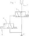
- Fig. 1 a simplified fluid scheme is shown with activated blocking air flow.
- the machine control (not shown) opens the pneumatic valve 3 via a first magnetic coil 5 and switches on the blocking air 1, so that it flows from the operational compressed air system 2 to the motor spindle.
- the bistable pneumatic valve 3 retains its switching state even after the supply voltage has ceased, so that the blocking air flow 1 continues to flow to the motor spindle after the machine has been switched off.
- the pneumatic valve 3 is not switched off electrically via another solenoid but via a pilot valve 4. This is designed as a miniature valve and is activated by a second solenoid 6.
- a follow-up timer 7 is provided which provides a switching pulse after a desired period of time available.
- the on-off switch of the machine is symbolically represented by a main switch 11.
- a capacitor 8 is charged by a power supply 9.
- the capacitor 8 is dimensioned so that it supplies the follow-up timer 7 at least for the duration of the follow-up time, for example 30 minutes, with power.
- the pilot valve 4 is switched via a separate transistor 10. This ensures that sufficient energy is available during the shutdown process.
Landscapes
- Engineering & Computer Science (AREA)
- Mechanical Engineering (AREA)
- Fluid-Pressure Circuits (AREA)
- Motor Or Generator Cooling System (AREA)
Description
- Die Erfindung betrifft eine Maschine mit einer Abschaltverzögerung für einen Sperrluftstrom, der gegen das Eindringen von Kühlflüssigkeit und/oder Schmutzpartikeln in ein zu schützendes Maschinenaggregat geführt wird. Empfindliche Maschinenaggregate werden häufig mit sogenannter Sperrluft beaufschlagt, um zu verhindern, dass Schmutzpartikel, Flüssigkeiten oder heiße Gase in diese eindringen und Schäden verursachen. Beispielsweise werden die Motorspindeln von Werkzeugmaschinen aus einer separaten Druckluftanlage mit Sperrluft gegen das Eindringen von Kühlflüssigkeit geschützt, um zu verhindern dass deren Lagerung beschädigt wird. Aus der
DE 40 15 241 A1 ist eine Werkzeugmaschinenspindel mit luftgekühlter Wälzlagerung bekannt. Dabei wird die Kühlluftquelle zusätzlich als Sperrluftquelle genutzt. Für den Austritt von Kühl- und Sperrluft sind an einem Wälzlager zwei Ringspalte vorgesehen, welche das Vermischen beider Luftströme verhindern. Mit dem Abschalten der Werkzeugmaschine wird diese stromlos. Dann können Verunreinigungen in die Spindel eindringen, wenn diese auf Umgebungstemperatur abkühlt und dabei Luft aus ihrer Umgebung einsaugt. DieDE 10 2007 007 343 A1 betrifft einen Staubschutzmechanismus für eine Spindelvorrichtung, der die beim Schneiden verwendete Flüssigkeit mit Druckluft daran hindert, in den Innenbereich der Spindelvorrichtung einzudringen. Wenn die Spindeldrehzahl einen vorbestimmten Wert einnimmt oder diesen unterschreitet, wird die zugeführte Druckluft reduziert. Gleichzeitig wird ein nicht näher definierter Zeitgeber auf eine Zeitspanne eingestellt. Nach Ablauf der Zeitspanne wird die Druckluftzufuhr unterbrochen. - Es ist die Aufgabe der vorliegenden Erfindung nach dem Ausschalten einer Maschine zu verhindern, dass Verunreinigungen in ein zu schützendes Maschinenaggregat eindringen. Gelöst wird diese Aufgabe mit einer Maschine nach Patentanspruch 1. Vorteilhafte Ausführungen ergeben sich aus den Unteransprüchen. Gemäß einem vorteilhaften Aspekt der Erfindung wird der Sperrluftstrom nach dem Abschalten der Maschine noch weiter aufrecht erhalten. Dazu ist ein Nachlauftimer vorgesehen, der nach Ablauf eines vorbestimmbaren Zeitintervalls ein entsprechendes Ventil schließt. Im Stand der Technik sind elektrische Verzögerungsschaltungen für vielfältige Schaltungsanwendungen bekannt. Diese sind auf die jeweiligen Einsatzverhältnisse zugeschnitten. Allen Verzögerungsschaltungen ist gemeinsam, dass ein zugeführtes Eingangssignal nach Ablauf einer gewünschten Zeitspanne am Ausgang zur Verfügung gestellt wird. Im Gegensatz zu diesen bekannten Verzögerungsschaltungen muss der Nachlauftimer für die Sperrluftstromabschaltung jedoch ohne permanente Stromversorgung auskommen, weil die Maschine nach dem Ausschalten stromlos geworden ist. Im Folgenden wird die Erfindung an Hand eines Ausführungsbeispiels näher beschrieben. Es zeigen:
- Fig. 1
- zeigt ein Fluid-Schema zum Schalten der Sperrluft
- Fig. 2
- zeigt einen Nachlauftimer in schematischer Darstellung
- In
Fig. 1 ist ein vereinfachtes Fluid-Schema bei eingeschaltetem Sperrluftstrom dargestellt. Die Maschinensteuerung (nicht dargestellt) öffnet über eine erste Magnetspule 5 das Pneumatikventil 3 und schaltet die Sperrluft 1 ein, so dass diese von der betrieblichen Druckluftanlage 2 zur Motorspindel strömt. Das bistabile Pneumatikventil 3 behält auch nach Wegfall der Versorgungsspannung seinen Schaltzustand bei, so dass der Sperrluftstrom 1 nach dem Ausschalten der Maschine weiterhin zur Motorspindel strömt. Besonders vorteilhaft wird das Pneumatikventil 3 nicht elektrisch über eine weitere Magnetspule sondern über ein Vorsteuerventil 4 ausgeschaltet. Dieses ist als Miniaturventil ausgeführt und wird über eine zweite Magnetspule 6 aktiviert. Zum Einstellen der gewünschten Verzögerung ist ein Nachlauftimer 7 vorgesehen, der nach Ablauf einer gewünschten Zeitspanne einen Schaltimpuls zur Verfügung stellt. Da zur Aktivierung der Magnetspule 6 nur eine geringe Energiemenge benötigt wird, kann der Nachlauftimer 7 besonders kostengünstig ausgeführt werden. Die Anordnung des Nachlauftimers 7 wird an Hand vonFig. 2 näher erläutert. Der Ein- Ausschalter der Maschine ist symbolisch durch einen Hauptschalter 11 dargestellt. Bei geschlossenem Hauptschalter 11 wird ein Kondensator 8 von einer Stromversorgung 9 aufgeladen. Der Kondensator 8 ist so dimensioniert, dass er den Nachlauftimer 7 mindestens für die Dauer der Nachlaufzeit, beispielsweise 30 Minuten, mit Strom versorgt. Vorteilhaft wird das Vorsteuerventil 4 über einen separaten Transistor 10 geschaltet. Auf diese Weise wird sichergestellt, dass beim Abschaltvorgang ausreichend Energie zur Verfügung steht. -
- 1
- Sperrluft
- 2
- Druckluftanlage
- 3
- Pneumatikventil
- 4
- Vorsteuerventil
- 5
- Erste Magnetspule
- 6
- Zweite Magnetspule
- 7
- Nachlauftimer
- 8
- Kondensator
- 9
- Stromversorgung
- 10
- Transistor
- 11
- Hauptschalter
Claims (4)
- Maschine mit einem Maschinenaggregat, mit einer Abschaltverzögerung für einen Sperrluftstrom (1) gegen das Eindringen von Kühlflüssigkeit und/oder Schmutzpartikeln in das zu schützende Maschinenaggregat und mit einem bistabilen Pneumatikventil (3), wobei der Sperrluftstrom (1) bei eingeschalteter Maschine von einer betrieblichen Druckluftanlage (2) über das Pneumatikventil (3) zum Maschinenaggregat strömt, wobei der Sperrluftstrom (1) nach dem Ausschalten der Maschine nach Ablauf einer gewünschten Zeitspanne selbsttätig abschaltbar ist, wobei die Zeitspanne über einen elektrischen Nachlauftimer (7) einstellbar ist und der Sperrluftstrom (1) bei stromloser Maschine abschaltbar ist,
dadurch gekennzeichnet,
dass das Pneumatikventil (3) über eine erste Magnetspule (5) in die Offenstellung und über ein Vorsteuerventil (4) in die Geschlossenstellung bewegbar ist. - Maschine nach Patentanspruch 1, dadurch gekennzeichnet, dass das Vorsteuerventil als Miniaturventil ausgeführt und über eine zweite Magnetspule (6) aktivierbar ist.
- Maschine nach Patentanspruch 1 oder 2, dadurch gekennzeichnet, dass als Energiespeicher für den Nachlauftimer (7) mindestens ein Kondensator (8) vorgesehen ist.
- Maschine nach einem der Patentansprüche 1 bis 3, dadurch gekennzeichnet, dass die zweite Magnetspule (6) am Vorsteuerventil (4) über einen separaten Transistor (10) schaltbar ist.
Applications Claiming Priority (2)
| Application Number | Priority Date | Filing Date | Title |
|---|---|---|---|
| DE201310015203 DE102013015203B4 (de) | 2013-09-13 | 2013-09-13 | Motorspindel für eine Werkzeugmaschine |
| PCT/DE2014/000439 WO2015035968A1 (de) | 2013-09-13 | 2014-08-26 | Abschaltverzögerung für sperrluftstrom |
Publications (2)
| Publication Number | Publication Date |
|---|---|
| EP3046726A1 EP3046726A1 (de) | 2016-07-27 |
| EP3046726B1 true EP3046726B1 (de) | 2019-05-22 |
Family
ID=52114024
Family Applications (1)
| Application Number | Title | Priority Date | Filing Date |
|---|---|---|---|
| EP14814686.3A Not-in-force EP3046726B1 (de) | 2013-09-13 | 2014-08-26 | Abschaltverzögerung für sperrluftstrom |
Country Status (3)
| Country | Link |
|---|---|
| EP (1) | EP3046726B1 (de) |
| DE (2) | DE102013015203B4 (de) |
| WO (1) | WO2015035968A1 (de) |
Family Cites Families (3)
| Publication number | Priority date | Publication date | Assignee | Title |
|---|---|---|---|---|
| DE4015241A1 (de) * | 1990-05-10 | 1991-11-14 | Universal Kugellager Gmbh | Werkzeugmaschinenspindellagerung |
| JP4897311B2 (ja) * | 2006-02-28 | 2012-03-14 | オークマ株式会社 | 主軸装置の防塵機構 |
| JP4938419B2 (ja) * | 2006-11-15 | 2012-05-23 | オークマ株式会社 | シール装置 |
-
2013
- 2013-09-13 DE DE201310015203 patent/DE102013015203B4/de active Active
-
2014
- 2014-08-26 DE DE112014004182.3T patent/DE112014004182A5/de not_active Ceased
- 2014-08-26 EP EP14814686.3A patent/EP3046726B1/de not_active Not-in-force
- 2014-08-26 WO PCT/DE2014/000439 patent/WO2015035968A1/de not_active Ceased
Non-Patent Citations (1)
| Title |
|---|
| None * |
Also Published As
| Publication number | Publication date |
|---|---|
| DE102013015203A1 (de) | 2015-03-19 |
| DE112014004182A5 (de) | 2016-06-02 |
| DE102013015203B4 (de) | 2015-05-13 |
| WO2015035968A1 (de) | 2015-03-19 |
| EP3046726A1 (de) | 2016-07-27 |
Similar Documents
| Publication | Publication Date | Title |
|---|---|---|
| WO2002102631A1 (de) | Elektrische lenkungsverriegelung | |
| DE102016115441A1 (de) | Elektro-mechanisches Filtersystem zum Reinigen von Luft in Schienenfahrzeugen | |
| EP3580769B1 (de) | Bistabile magnetventil-einrichtung und verfahren zu deren überwachung | |
| DE102011081183A1 (de) | Ventil zur Steuerung von Volumenströmen | |
| DE102015010366A1 (de) | Klappensystem für ein fahrzeug | |
| DE102014105946B4 (de) | Drehtischvorrichtung | |
| DE102009050788A1 (de) | Kondensator-Vorladeschaltung mit Hochspannungsbus | |
| WO2015082038A1 (de) | Ventileinrichtung | |
| DE4403375A1 (de) | Einrichtung und Verfahren zum Steuern eines induktiven Verbrauchers | |
| DE102018117528A1 (de) | Entladeschaltungen zum Entladen von induktiven Elementen mit Temperaturschutz | |
| DE102013015203B4 (de) | Motorspindel für eine Werkzeugmaschine | |
| DE10129153A1 (de) | Elektromagnetisches Ventil mit Haltestromabsenkung | |
| DE102011110929A1 (de) | Hand-Werkzeugmaschine mit einer elektrischen Bremseinrichtung | |
| DE102012010868A1 (de) | Verfahren und Vorrichtung zum Überwachen einer Aktuatorvorrichtung | |
| DE102010056277B4 (de) | Absperrarmatur | |
| DE202007011304U1 (de) | Vorrichtung zur Überwachung eines Kühlkreislaufs | |
| DE2026842B2 (de) | Schaltungsanordnung fuer ein elektromotorisch betriebenes ventil | |
| DE102012208122B4 (de) | Schaltschütz | |
| EP2181770B1 (de) | Zentrifuge | |
| DE2503623A1 (de) | Belueftungseinrichtung fuer einen elektrischen schaltschrank | |
| DE102016107980A1 (de) | Bistabile elektromagnetische Aktorvorrichtung | |
| DE3337095C2 (de) | ||
| DE4403309A1 (de) | Steuergerät mit einem ersten und zweiten elektrischen Versorgungseingang | |
| DE3730517A1 (de) | Schaltungsanordnung fuer die erregung und entregung eines bistabilen relais | |
| DE10216527A1 (de) | Einrichtung zur Drehmomentbegrenzung eines Werkzeugs und Verfahren zu deren Betrieb |
Legal Events
| Date | Code | Title | Description |
|---|---|---|---|
| PUAI | Public reference made under article 153(3) epc to a published international application that has entered the european phase |
Free format text: ORIGINAL CODE: 0009012 |
|
| 17P | Request for examination filed |
Effective date: 20160411 |
|
| AK | Designated contracting states |
Kind code of ref document: A1 Designated state(s): AL AT BE BG CH CY CZ DE DK EE ES FI FR GB GR HR HU IE IS IT LI LT LU LV MC MK MT NL NO PL PT RO RS SE SI SK SM TR |
|
| AX | Request for extension of the european patent |
Extension state: BA ME |
|
| DAX | Request for extension of the european patent (deleted) | ||
| GRAP | Despatch of communication of intention to grant a patent |
Free format text: ORIGINAL CODE: EPIDOSNIGR1 |
|
| STAA | Information on the status of an ep patent application or granted ep patent |
Free format text: STATUS: GRANT OF PATENT IS INTENDED |
|
| INTG | Intention to grant announced |
Effective date: 20181203 |
|
| GRAS | Grant fee paid |
Free format text: ORIGINAL CODE: EPIDOSNIGR3 |
|
| GRAA | (expected) grant |
Free format text: ORIGINAL CODE: 0009210 |
|
| STAA | Information on the status of an ep patent application or granted ep patent |
Free format text: STATUS: THE PATENT HAS BEEN GRANTED |
|
| AK | Designated contracting states |
Kind code of ref document: B1 Designated state(s): AL AT BE BG CH CY CZ DE DK EE ES FI FR GB GR HR HU IE IS IT LI LT LU LV MC MK MT NL NO PL PT RO RS SE SI SK SM TR |
|
| REG | Reference to a national code |
Ref country code: GB Ref legal event code: FG4D Free format text: NOT ENGLISH |
|
| REG | Reference to a national code |
Ref country code: CH Ref legal event code: EP |
|
| REG | Reference to a national code |
Ref country code: IE Ref legal event code: FG4D Free format text: LANGUAGE OF EP DOCUMENT: GERMAN |
|
| REG | Reference to a national code |
Ref country code: DE Ref legal event code: R096 Ref document number: 502014011785 Country of ref document: DE |
|
| REG | Reference to a national code |
Ref country code: AT Ref legal event code: REF Ref document number: 1135524 Country of ref document: AT Kind code of ref document: T Effective date: 20190615 |
|
| REG | Reference to a national code |
Ref country code: NL Ref legal event code: MP Effective date: 20190522 |
|
| REG | Reference to a national code |
Ref country code: LT Ref legal event code: MG4D |
|
| PG25 | Lapsed in a contracting state [announced via postgrant information from national office to epo] |
Ref country code: FI Free format text: LAPSE BECAUSE OF FAILURE TO SUBMIT A TRANSLATION OF THE DESCRIPTION OR TO PAY THE FEE WITHIN THE PRESCRIBED TIME-LIMIT Effective date: 20190522 Ref country code: NL Free format text: LAPSE BECAUSE OF FAILURE TO SUBMIT A TRANSLATION OF THE DESCRIPTION OR TO PAY THE FEE WITHIN THE PRESCRIBED TIME-LIMIT Effective date: 20190522 Ref country code: SE Free format text: LAPSE BECAUSE OF FAILURE TO SUBMIT A TRANSLATION OF THE DESCRIPTION OR TO PAY THE FEE WITHIN THE PRESCRIBED TIME-LIMIT Effective date: 20190522 Ref country code: LT Free format text: LAPSE BECAUSE OF FAILURE TO SUBMIT A TRANSLATION OF THE DESCRIPTION OR TO PAY THE FEE WITHIN THE PRESCRIBED TIME-LIMIT Effective date: 20190522 Ref country code: ES Free format text: LAPSE BECAUSE OF FAILURE TO SUBMIT A TRANSLATION OF THE DESCRIPTION OR TO PAY THE FEE WITHIN THE PRESCRIBED TIME-LIMIT Effective date: 20190522 Ref country code: AL Free format text: LAPSE BECAUSE OF FAILURE TO SUBMIT A TRANSLATION OF THE DESCRIPTION OR TO PAY THE FEE WITHIN THE PRESCRIBED TIME-LIMIT Effective date: 20190522 Ref country code: PT Free format text: LAPSE BECAUSE OF FAILURE TO SUBMIT A TRANSLATION OF THE DESCRIPTION OR TO PAY THE FEE WITHIN THE PRESCRIBED TIME-LIMIT Effective date: 20190922 Ref country code: NO Free format text: LAPSE BECAUSE OF FAILURE TO SUBMIT A TRANSLATION OF THE DESCRIPTION OR TO PAY THE FEE WITHIN THE PRESCRIBED TIME-LIMIT Effective date: 20190822 Ref country code: HR Free format text: LAPSE BECAUSE OF FAILURE TO SUBMIT A TRANSLATION OF THE DESCRIPTION OR TO PAY THE FEE WITHIN THE PRESCRIBED TIME-LIMIT Effective date: 20190522 |
|
| PG25 | Lapsed in a contracting state [announced via postgrant information from national office to epo] |
Ref country code: LV Free format text: LAPSE BECAUSE OF FAILURE TO SUBMIT A TRANSLATION OF THE DESCRIPTION OR TO PAY THE FEE WITHIN THE PRESCRIBED TIME-LIMIT Effective date: 20190522 Ref country code: BG Free format text: LAPSE BECAUSE OF FAILURE TO SUBMIT A TRANSLATION OF THE DESCRIPTION OR TO PAY THE FEE WITHIN THE PRESCRIBED TIME-LIMIT Effective date: 20190822 Ref country code: GR Free format text: LAPSE BECAUSE OF FAILURE TO SUBMIT A TRANSLATION OF THE DESCRIPTION OR TO PAY THE FEE WITHIN THE PRESCRIBED TIME-LIMIT Effective date: 20190823 Ref country code: RS Free format text: LAPSE BECAUSE OF FAILURE TO SUBMIT A TRANSLATION OF THE DESCRIPTION OR TO PAY THE FEE WITHIN THE PRESCRIBED TIME-LIMIT Effective date: 20190522 |
|
| PG25 | Lapsed in a contracting state [announced via postgrant information from national office to epo] |
Ref country code: CZ Free format text: LAPSE BECAUSE OF FAILURE TO SUBMIT A TRANSLATION OF THE DESCRIPTION OR TO PAY THE FEE WITHIN THE PRESCRIBED TIME-LIMIT Effective date: 20190522 Ref country code: RO Free format text: LAPSE BECAUSE OF FAILURE TO SUBMIT A TRANSLATION OF THE DESCRIPTION OR TO PAY THE FEE WITHIN THE PRESCRIBED TIME-LIMIT Effective date: 20190522 Ref country code: EE Free format text: LAPSE BECAUSE OF FAILURE TO SUBMIT A TRANSLATION OF THE DESCRIPTION OR TO PAY THE FEE WITHIN THE PRESCRIBED TIME-LIMIT Effective date: 20190522 Ref country code: DK Free format text: LAPSE BECAUSE OF FAILURE TO SUBMIT A TRANSLATION OF THE DESCRIPTION OR TO PAY THE FEE WITHIN THE PRESCRIBED TIME-LIMIT Effective date: 20190522 Ref country code: SK Free format text: LAPSE BECAUSE OF FAILURE TO SUBMIT A TRANSLATION OF THE DESCRIPTION OR TO PAY THE FEE WITHIN THE PRESCRIBED TIME-LIMIT Effective date: 20190522 |
|
| REG | Reference to a national code |
Ref country code: DE Ref legal event code: R097 Ref document number: 502014011785 Country of ref document: DE |
|
| PG25 | Lapsed in a contracting state [announced via postgrant information from national office to epo] |
Ref country code: SM Free format text: LAPSE BECAUSE OF FAILURE TO SUBMIT A TRANSLATION OF THE DESCRIPTION OR TO PAY THE FEE WITHIN THE PRESCRIBED TIME-LIMIT Effective date: 20190522 Ref country code: IT Free format text: LAPSE BECAUSE OF FAILURE TO SUBMIT A TRANSLATION OF THE DESCRIPTION OR TO PAY THE FEE WITHIN THE PRESCRIBED TIME-LIMIT Effective date: 20190522 |
|
| PLBE | No opposition filed within time limit |
Free format text: ORIGINAL CODE: 0009261 |
|
| STAA | Information on the status of an ep patent application or granted ep patent |
Free format text: STATUS: NO OPPOSITION FILED WITHIN TIME LIMIT |
|
| PG25 | Lapsed in a contracting state [announced via postgrant information from national office to epo] |
Ref country code: TR Free format text: LAPSE BECAUSE OF FAILURE TO SUBMIT A TRANSLATION OF THE DESCRIPTION OR TO PAY THE FEE WITHIN THE PRESCRIBED TIME-LIMIT Effective date: 20190522 |
|
| 26N | No opposition filed |
Effective date: 20200225 |
|
| GBPC | Gb: european patent ceased through non-payment of renewal fee |
Effective date: 20190826 |
|
| PG25 | Lapsed in a contracting state [announced via postgrant information from national office to epo] |
Ref country code: PL Free format text: LAPSE BECAUSE OF FAILURE TO SUBMIT A TRANSLATION OF THE DESCRIPTION OR TO PAY THE FEE WITHIN THE PRESCRIBED TIME-LIMIT Effective date: 20190522 |
|
| PGFP | Annual fee paid to national office [announced via postgrant information from national office to epo] |
Ref country code: DE Payment date: 20200226 Year of fee payment: 6 |
|
| PG25 | Lapsed in a contracting state [announced via postgrant information from national office to epo] |
Ref country code: SI Free format text: LAPSE BECAUSE OF FAILURE TO SUBMIT A TRANSLATION OF THE DESCRIPTION OR TO PAY THE FEE WITHIN THE PRESCRIBED TIME-LIMIT Effective date: 20190522 Ref country code: MC Free format text: LAPSE BECAUSE OF FAILURE TO SUBMIT A TRANSLATION OF THE DESCRIPTION OR TO PAY THE FEE WITHIN THE PRESCRIBED TIME-LIMIT Effective date: 20190522 Ref country code: CH Free format text: LAPSE BECAUSE OF NON-PAYMENT OF DUE FEES Effective date: 20190831 Ref country code: LU Free format text: LAPSE BECAUSE OF NON-PAYMENT OF DUE FEES Effective date: 20190826 Ref country code: LI Free format text: LAPSE BECAUSE OF NON-PAYMENT OF DUE FEES Effective date: 20190831 |
|
| REG | Reference to a national code |
Ref country code: BE Ref legal event code: MM Effective date: 20190831 |
|
| PG25 | Lapsed in a contracting state [announced via postgrant information from national office to epo] |
Ref country code: IE Free format text: LAPSE BECAUSE OF NON-PAYMENT OF DUE FEES Effective date: 20190826 Ref country code: FR Free format text: LAPSE BECAUSE OF NON-PAYMENT OF DUE FEES Effective date: 20190831 |
|
| PG25 | Lapsed in a contracting state [announced via postgrant information from national office to epo] |
Ref country code: BE Free format text: LAPSE BECAUSE OF NON-PAYMENT OF DUE FEES Effective date: 20190831 Ref country code: GB Free format text: LAPSE BECAUSE OF NON-PAYMENT OF DUE FEES Effective date: 20190826 |
|
| REG | Reference to a national code |
Ref country code: AT Ref legal event code: MM01 Ref document number: 1135524 Country of ref document: AT Kind code of ref document: T Effective date: 20190826 |
|
| PG25 | Lapsed in a contracting state [announced via postgrant information from national office to epo] |
Ref country code: AT Free format text: LAPSE BECAUSE OF NON-PAYMENT OF DUE FEES Effective date: 20190826 |
|
| REG | Reference to a national code |
Ref country code: DE Ref legal event code: R119 Ref document number: 502014011785 Country of ref document: DE |
|
| PG25 | Lapsed in a contracting state [announced via postgrant information from national office to epo] |
Ref country code: CY Free format text: LAPSE BECAUSE OF FAILURE TO SUBMIT A TRANSLATION OF THE DESCRIPTION OR TO PAY THE FEE WITHIN THE PRESCRIBED TIME-LIMIT Effective date: 20190522 |
|
| PG25 | Lapsed in a contracting state [announced via postgrant information from national office to epo] |
Ref country code: IS Free format text: LAPSE BECAUSE OF FAILURE TO SUBMIT A TRANSLATION OF THE DESCRIPTION OR TO PAY THE FEE WITHIN THE PRESCRIBED TIME-LIMIT Effective date: 20190922 |
|
| PG25 | Lapsed in a contracting state [announced via postgrant information from national office to epo] |
Ref country code: HU Free format text: LAPSE BECAUSE OF FAILURE TO SUBMIT A TRANSLATION OF THE DESCRIPTION OR TO PAY THE FEE WITHIN THE PRESCRIBED TIME-LIMIT; INVALID AB INITIO Effective date: 20140826 Ref country code: MT Free format text: LAPSE BECAUSE OF FAILURE TO SUBMIT A TRANSLATION OF THE DESCRIPTION OR TO PAY THE FEE WITHIN THE PRESCRIBED TIME-LIMIT Effective date: 20190522 Ref country code: DE Free format text: LAPSE BECAUSE OF NON-PAYMENT OF DUE FEES Effective date: 20210302 |
|
| PG25 | Lapsed in a contracting state [announced via postgrant information from national office to epo] |
Ref country code: MK Free format text: LAPSE BECAUSE OF FAILURE TO SUBMIT A TRANSLATION OF THE DESCRIPTION OR TO PAY THE FEE WITHIN THE PRESCRIBED TIME-LIMIT Effective date: 20190522 |