EP3046671B1 - Vorrichtung zur herstellung eines gleichmässigen temperaturverlaufs für einen thermocycler - Google Patents
Vorrichtung zur herstellung eines gleichmässigen temperaturverlaufs für einen thermocycler Download PDFInfo
- Publication number
- EP3046671B1 EP3046671B1 EP14777985.4A EP14777985A EP3046671B1 EP 3046671 B1 EP3046671 B1 EP 3046671B1 EP 14777985 A EP14777985 A EP 14777985A EP 3046671 B1 EP3046671 B1 EP 3046671B1
- Authority
- EP
- European Patent Office
- Prior art keywords
- thermal
- sample block
- temperature
- various embodiments
- tnu
- Prior art date
- Legal status (The legal status is an assumption and is not a legal conclusion. Google has not performed a legal analysis and makes no representation as to the accuracy of the status listed.)
- Active
Links
- 238000004891 communication Methods 0.000 claims description 22
- 238000006243 chemical reaction Methods 0.000 claims description 7
- 238000000034 method Methods 0.000 description 53
- 239000010410 layer Substances 0.000 description 23
- 238000010438 heat treatment Methods 0.000 description 17
- 238000010586 diagram Methods 0.000 description 14
- 238000003752 polymerase chain reaction Methods 0.000 description 12
- 230000009977 dual effect Effects 0.000 description 10
- 239000000463 material Substances 0.000 description 10
- 230000008569 process Effects 0.000 description 10
- 238000009529 body temperature measurement Methods 0.000 description 9
- 230000001276 controlling effect Effects 0.000 description 8
- 238000005259 measurement Methods 0.000 description 7
- 230000000694 effects Effects 0.000 description 6
- 239000007788 liquid Substances 0.000 description 6
- 239000008188 pellet Substances 0.000 description 6
- 238000012545 processing Methods 0.000 description 6
- 239000004065 semiconductor Substances 0.000 description 6
- 239000000853 adhesive Substances 0.000 description 5
- 230000001070 adhesive effect Effects 0.000 description 5
- 238000001816 cooling Methods 0.000 description 5
- 230000001419 dependent effect Effects 0.000 description 5
- 230000006872 improvement Effects 0.000 description 5
- 238000003860 storage Methods 0.000 description 5
- 238000005382 thermal cycling Methods 0.000 description 5
- 239000004820 Pressure-sensitive adhesive Substances 0.000 description 4
- 230000008878 coupling Effects 0.000 description 4
- 238000010168 coupling process Methods 0.000 description 4
- 238000005859 coupling reaction Methods 0.000 description 4
- 230000001351 cycling effect Effects 0.000 description 4
- 229910052751 metal Inorganic materials 0.000 description 4
- 239000002184 metal Substances 0.000 description 4
- 230000003287 optical effect Effects 0.000 description 4
- 230000003068 static effect Effects 0.000 description 4
- 239000000758 substrate Substances 0.000 description 4
- 230000007704 transition Effects 0.000 description 4
- 230000000712 assembly Effects 0.000 description 3
- 238000000429 assembly Methods 0.000 description 3
- 238000010276 construction Methods 0.000 description 3
- 238000013500 data storage Methods 0.000 description 3
- 238000013461 design Methods 0.000 description 3
- 238000009826 distribution Methods 0.000 description 3
- 239000000499 gel Substances 0.000 description 3
- 239000011541 reaction mixture Substances 0.000 description 3
- 229920002379 silicone rubber Polymers 0.000 description 3
- 239000004945 silicone rubber Substances 0.000 description 3
- 239000000126 substance Substances 0.000 description 3
- RYGMFSIKBFXOCR-UHFFFAOYSA-N Copper Chemical compound [Cu] RYGMFSIKBFXOCR-UHFFFAOYSA-N 0.000 description 2
- XUIMIQQOPSSXEZ-UHFFFAOYSA-N Silicon Chemical compound [Si] XUIMIQQOPSSXEZ-UHFFFAOYSA-N 0.000 description 2
- 239000012790 adhesive layer Substances 0.000 description 2
- 238000000137 annealing Methods 0.000 description 2
- 238000004590 computer program Methods 0.000 description 2
- 229910052802 copper Inorganic materials 0.000 description 2
- 239000010949 copper Substances 0.000 description 2
- 230000001627 detrimental effect Effects 0.000 description 2
- 229920001971 elastomer Polymers 0.000 description 2
- 230000000670 limiting effect Effects 0.000 description 2
- 238000004519 manufacturing process Methods 0.000 description 2
- TWNQGVIAIRXVLR-UHFFFAOYSA-N oxo(oxoalumanyloxy)alumane Chemical compound O=[Al]O[Al]=O TWNQGVIAIRXVLR-UHFFFAOYSA-N 0.000 description 2
- BASFCYQUMIYNBI-UHFFFAOYSA-N platinum Chemical compound [Pt] BASFCYQUMIYNBI-UHFFFAOYSA-N 0.000 description 2
- 230000008092 positive effect Effects 0.000 description 2
- 230000001105 regulatory effect Effects 0.000 description 2
- 229910052710 silicon Inorganic materials 0.000 description 2
- 239000010703 silicon Substances 0.000 description 2
- 238000012360 testing method Methods 0.000 description 2
- 239000011800 void material Substances 0.000 description 2
- ASJSAQIRZKANQN-CRCLSJGQSA-N 2-deoxy-D-ribose Chemical compound OC[C@@H](O)[C@@H](O)CC=O ASJSAQIRZKANQN-CRCLSJGQSA-N 0.000 description 1
- FRWYFWZENXDZMU-UHFFFAOYSA-N 2-iodoquinoline Chemical compound C1=CC=CC2=NC(I)=CC=C21 FRWYFWZENXDZMU-UHFFFAOYSA-N 0.000 description 1
- 229920002799 BoPET Polymers 0.000 description 1
- 102000053602 DNA Human genes 0.000 description 1
- 108020004414 DNA Proteins 0.000 description 1
- 230000004544 DNA amplification Effects 0.000 description 1
- 239000004593 Epoxy Substances 0.000 description 1
- 239000005041 Mylar™ Substances 0.000 description 1
- 239000004642 Polyimide Substances 0.000 description 1
- 229910000577 Silicon-germanium Inorganic materials 0.000 description 1
- LEVVHYCKPQWKOP-UHFFFAOYSA-N [Si].[Ge] Chemical compound [Si].[Ge] LEVVHYCKPQWKOP-UHFFFAOYSA-N 0.000 description 1
- 239000002253 acid Substances 0.000 description 1
- 230000001154 acute effect Effects 0.000 description 1
- 230000002411 adverse Effects 0.000 description 1
- 239000011543 agarose gel Substances 0.000 description 1
- 229910052782 aluminium Inorganic materials 0.000 description 1
- XAGFODPZIPBFFR-UHFFFAOYSA-N aluminium Chemical compound [Al] XAGFODPZIPBFFR-UHFFFAOYSA-N 0.000 description 1
- PNEYBMLMFCGWSK-UHFFFAOYSA-N aluminium oxide Inorganic materials [O-2].[O-2].[O-2].[Al+3].[Al+3] PNEYBMLMFCGWSK-UHFFFAOYSA-N 0.000 description 1
- 230000003321 amplification Effects 0.000 description 1
- 238000004458 analytical method Methods 0.000 description 1
- LTPBRCUWZOMYOC-UHFFFAOYSA-N beryllium oxide Inorganic materials O=[Be] LTPBRCUWZOMYOC-UHFFFAOYSA-N 0.000 description 1
- 229910052797 bismuth Inorganic materials 0.000 description 1
- JCXGWMGPZLAOME-UHFFFAOYSA-N bismuth atom Chemical compound [Bi] JCXGWMGPZLAOME-UHFFFAOYSA-N 0.000 description 1
- 230000015556 catabolic process Effects 0.000 description 1
- 230000008859 change Effects 0.000 description 1
- 230000000295 complement effect Effects 0.000 description 1
- PMHQVHHXPFUNSP-UHFFFAOYSA-M copper(1+);methylsulfanylmethane;bromide Chemical compound Br[Cu].CSC PMHQVHHXPFUNSP-UHFFFAOYSA-M 0.000 description 1
- 238000012937 correction Methods 0.000 description 1
- 238000006731 degradation reaction Methods 0.000 description 1
- 230000001934 delay Effects 0.000 description 1
- 238000009792 diffusion process Methods 0.000 description 1
- 238000001962 electrophoresis Methods 0.000 description 1
- 238000005516 engineering process Methods 0.000 description 1
- 125000003700 epoxy group Chemical group 0.000 description 1
- 238000011534 incubation Methods 0.000 description 1
- 238000002955 isolation Methods 0.000 description 1
- 238000002156 mixing Methods 0.000 description 1
- 238000012986 modification Methods 0.000 description 1
- 230000004048 modification Effects 0.000 description 1
- 238000009828 non-uniform distribution Methods 0.000 description 1
- 238000003199 nucleic acid amplification method Methods 0.000 description 1
- 238000013021 overheating Methods 0.000 description 1
- 239000004033 plastic Substances 0.000 description 1
- 229910052697 platinum Inorganic materials 0.000 description 1
- 229920003223 poly(pyromellitimide-1,4-diphenyl ether) Polymers 0.000 description 1
- 229920000647 polyepoxide Polymers 0.000 description 1
- 229920001721 polyimide Polymers 0.000 description 1
- 229920001296 polysiloxane Polymers 0.000 description 1
- 230000000135 prohibitive effect Effects 0.000 description 1
- 238000005086 pumping Methods 0.000 description 1
- 238000013139 quantization Methods 0.000 description 1
- 238000003753 real-time PCR Methods 0.000 description 1
- 230000009467 reduction Effects 0.000 description 1
- 230000002829 reductive effect Effects 0.000 description 1
- QEBDLIWRLCPLCY-UHFFFAOYSA-N selanylidenebismuth Chemical compound [Bi]=[Se] QEBDLIWRLCPLCY-UHFFFAOYSA-N 0.000 description 1
- OCGWQDWYSQAFTO-UHFFFAOYSA-N tellanylidenelead Chemical compound [Pb]=[Te] OCGWQDWYSQAFTO-UHFFFAOYSA-N 0.000 description 1
- XSOKHXFFCGXDJZ-UHFFFAOYSA-N telluride(2-) Chemical compound [Te-2] XSOKHXFFCGXDJZ-UHFFFAOYSA-N 0.000 description 1
- 238000012546 transfer Methods 0.000 description 1
Images


Classifications
-
- B—PERFORMING OPERATIONS; TRANSPORTING
- B01—PHYSICAL OR CHEMICAL PROCESSES OR APPARATUS IN GENERAL
- B01L—CHEMICAL OR PHYSICAL LABORATORY APPARATUS FOR GENERAL USE
- B01L7/00—Heating or cooling apparatus; Heat insulating devices
- B01L7/52—Heating or cooling apparatus; Heat insulating devices with provision for submitting samples to a predetermined sequence of different temperatures, e.g. for treating nucleic acid samples
-
- B—PERFORMING OPERATIONS; TRANSPORTING
- B01—PHYSICAL OR CHEMICAL PROCESSES OR APPARATUS IN GENERAL
- B01L—CHEMICAL OR PHYSICAL LABORATORY APPARATUS FOR GENERAL USE
- B01L2200/00—Solutions for specific problems relating to chemical or physical laboratory apparatus
- B01L2200/14—Process control and prevention of errors
- B01L2200/143—Quality control, feedback systems
- B01L2200/147—Employing temperature sensors
-
- B—PERFORMING OPERATIONS; TRANSPORTING
- B01—PHYSICAL OR CHEMICAL PROCESSES OR APPARATUS IN GENERAL
- B01L—CHEMICAL OR PHYSICAL LABORATORY APPARATUS FOR GENERAL USE
- B01L2300/00—Additional constructional details
- B01L2300/08—Geometry, shape and general structure
- B01L2300/0809—Geometry, shape and general structure rectangular shaped
- B01L2300/0829—Multi-well plates; Microtitration plates
-
- B—PERFORMING OPERATIONS; TRANSPORTING
- B01—PHYSICAL OR CHEMICAL PROCESSES OR APPARATUS IN GENERAL
- B01L—CHEMICAL OR PHYSICAL LABORATORY APPARATUS FOR GENERAL USE
- B01L2300/00—Additional constructional details
- B01L2300/08—Geometry, shape and general structure
- B01L2300/0848—Specific forms of parts of containers
-
- B—PERFORMING OPERATIONS; TRANSPORTING
- B01—PHYSICAL OR CHEMICAL PROCESSES OR APPARATUS IN GENERAL
- B01L—CHEMICAL OR PHYSICAL LABORATORY APPARATUS FOR GENERAL USE
- B01L2300/00—Additional constructional details
- B01L2300/08—Geometry, shape and general structure
- B01L2300/0887—Laminated structure
-
- B—PERFORMING OPERATIONS; TRANSPORTING
- B01—PHYSICAL OR CHEMICAL PROCESSES OR APPARATUS IN GENERAL
- B01L—CHEMICAL OR PHYSICAL LABORATORY APPARATUS FOR GENERAL USE
- B01L2300/00—Additional constructional details
- B01L2300/12—Specific details about materials
-
- B—PERFORMING OPERATIONS; TRANSPORTING
- B01—PHYSICAL OR CHEMICAL PROCESSES OR APPARATUS IN GENERAL
- B01L—CHEMICAL OR PHYSICAL LABORATORY APPARATUS FOR GENERAL USE
- B01L2300/00—Additional constructional details
- B01L2300/18—Means for temperature control
- B01L2300/1805—Conductive heating, heat from thermostatted solids is conducted to receptacles, e.g. heating plates, blocks
- B01L2300/1822—Conductive heating, heat from thermostatted solids is conducted to receptacles, e.g. heating plates, blocks using Peltier elements
Definitions
- the present disclosure generally relates to apparatuses, systems and methods for thermocycler devices.
- To amplify DNA (Deoxyribose Nucliec Acid) using the PCR process involves cycling a specially constituted liquid reaction mixture through several different temperature incubation periods.
- the reaction mixture is comprised of various components including the DNA to be amplified and at least two primers sufficiently complementary to the sample DNA to be able to create extension products of the DNA being amplified.
- a key to PCR is the concept of thermal cycling: alternating steps of denaturing DNA, annealing short primers to the resulting single strands, and extending those primers to make new copies of double-stranded DNA. In thermal cycling the PCR reaction mixture is repeatedly cycled from high temperatures of around 95° C. for denaturing the DNA, to lower temperatures of approximately 50° C. to 70° C. for primer annealing and extension.
- sample tubes are inserted into sample wells on a metal block.
- the temperature of the metal block is cycled according to prescribed temperatures and times specified by the user in a PCR protocol.
- the cycling is controlled by a computer and associated electronics.
- the samples in the various tubes experience similar changes in temperature.
- differences in sample temperature can be generated by non-uniformity of temperature from region to region within the sample metal block. Temperature gradients exist within the material of the block, causing some samples placed on the block to have different temperatures than others at particular times in the cycle. These differences in temperature and delays in heat transfer can cause the yield of the PCR process to differ from sample vial to sample vial.
- US 2013/157376 A1 discloses methods, devices, and systems for calibrating heat sources of thermal cyclers.
- a thermal-cycling device for thermally processing at least one substance carried by a thermally-conductive microwell plate, which includes a heating-cooling unit that may be placed in thermal contact with a surface of the microwell plate.
- US 2010/116896 A1 discloses a thermostat apparatus for simultaneous thermostatting of at least one sample that is contained, e.g., in sample vessels, having receptacles for receiving the samples or sample vessels, the apparatus having at least one thermostat device for generation of a desired temperature or temperature profile, having a control device for regulating the heating and/or cooling power of the at least one thermostat device, and having at least one regulating temperature sensor that is provided to determine a parameter that is indicative of the temperature and is connected to the control device.
- thermocycler sample block Apparatuses, systems, and methods for providing thermal uniformity throughout a thermocycler sample block are disclosed. Systems and methods are described but not claimed.
- thermoelectric device including a sample block and two or more thermoelectric devices.
- the sample block has a top surface configured to receive a plurality of reaction vessels and an opposing bottom surface.
- the thermoelectric devices are operably coupled to the sample block, wherein each thermoelectric device includes a housing for a thermal sensor and a thermal control interface with a controller.
- Each thermoelectric device is further configured to operate independently from each other to provide a substantially uniform temperature profile throughout the sample block.
- thermoelectric device including a first thermal conducting layer, a second thermal conducting layer, a plurality of Peltier elements and a thermal sensor, is disclosed.
- the Peltier elements are comprised of a semiconductor material and are sandwiched in between the first and the second thermal conducting layers.
- the thermal sensor is housed in between the first and the second thermal conducting layers.
- thermoelectric device including a first thermal conducting layer, a second thermal conducting layer, a plurality of Peltier elements and an open channel, is disclosed.
- the first and second thermal conducting layers have inner and outer surfaces.
- the plurality of Peltier elements comprised of semiconductor material that are adjacent to the inner surface of the first and second thermal conducting layers.
- the open channel is carved out of the first thermal conducting layer and the plurality of Peltier elements exposing the inner surface of the second thermal conducting layer.
- the open channel is configured to contain a thermal sensor.
- a method for controlling sample block temperature is disclosed.
- a block assembly with a sample block and two or more thermoelectric devices (each housing a unique thermal sensor), is provided.
- the two or more thermoelectric devices are paired to their respective unique thermal sensors to form a thermal unit.
- the temperature of each thermal unit is independently controlled with a controller to provide a substantially uniform temperature profile throughout the sample block.
- the sample block assembly includes a sample block and two or more thermoelectric devices (each hosing a unique thermal sensor) in thermal communication with the sample block.
- the sample block is configured to receive a plurality of reaction vessels.
- the controller includes a computer processing unit with machine executable instructions and two or more communication ports.
- each port is operably connected to one of the two or more thermoelectric devices and their respective thermal sensor.
- the machine executable instructions are configured to individually adjust the temperature of each thermoelectric device based on the temperature measurements from their respective thermal sensor to provide a substantially uniform temperature profile throughout the sample block.
- a thermal block assembly with two or more sample blocks, two or more sets of thermoelectric devices, a thermal control interface, and a controller is disclosed.
- Each sample block has a top surface configured to receive a plurality of reaction vessels and an opposing bottom surface.
- Each set of thermo electric devices is operably coupled to each sample block.
- the thermal control interface is in communications with the controller.
- the thermal block assembly comprises at least one sample block, at least one set of thermoelectric devices, a thermal control interface and a controller.
- the sample block has a top surface configured to receive a plurality of reaction vessels and an opposing bottom surface.
- the thermoelectric device is operable coupled to the sample block.
- the thermal control interface is in communications with the controller.
- thermocycler sample block Embodiments of apparatuses, and examples of systems and methods for providing thermal uniformity throughout a thermocycler sample block are described in this specification.
- the section headings used herein are for organizational purposes only and are not to be construed as limiting the described subject matter in any way.
- the specification may have presented a method and/or process as a particular sequence of steps.
- the method or process should not be limited to the particular sequence of steps described.
- other sequences of steps may be possible. Therefore, the particular order of the steps set forth in the specification should not be construed as limitations on the claims.
- the claims directed to the method and/or process should not be limited to the performance of their steps in the order written, and one skilled in the art can readily appreciate that the sequences may be varied and still remain within the scope of the various embodiments.
- Some of the examples described herein can be practiced using various computer system configurations including hand-held devices, microprocessor systems, microprocessor-based or programmable consumer electronics, minicomputers, mainframe computers and the like.
- the examples can also be practiced in distributing computing environments where tasks are performed by remote processing devices that are linked through a network.
- any of the operations that form part of the examples described herein can be useful as machine operations.
- the examples described herein can also relate to a device or an apparatus for performing these operations.
- the apparatuses, systems and methods described herein can be specially constructed for the required purposes or it may be a general purpose computer selectively activated or configured by a computer program stored in the computer.
- various general purpose machines may be used with computer programs written in accordance with the teachings herein, or it may be more convenient to construct a more specialized apparatus to perform the required operations.
- Certain examples can also be embodied as computer readable code on a computer readable medium.
- the computer readable medium is any data storage device that can store data, which can thereafter be read by a computer system. Examples of the computer readable medium include hard drives, network attached storage (NAS), read-only memory, random-access memory, CD-ROMs, CD-Rs, CD-RWs, magnetic tapes, and other optical, FLASH memory and non-optical data storage devices.
- the computer readable medium can also be distributed over a network coupled computer systems so that the computer readable code is stored and executed in a distributed fashion.
- PCR it can be desirable to change the sample temperature between the required temperatures in the cycle as quickly as possible for several reasons.
- the chemical reaction has an optimum temperature for each of its stages and as such less time spent at non-optimum temperatures can mean a better chemical result is achieved.
- a minimum time is usually required at any given set point which sets minimum cycle time for each protocol and any time spent in transition between set points adds to this minimum time. Since the number of cycles is usually quite large, this transition time can significantly add to the total time needed to complete the amplification.
- the absolute temperature that each reaction tube attains during each step of the protocol is critical to the yield of product. As the products are frequently subjected to quantization, the product yield from tube to tube must be as uniform as possible and therefore both the steady-state and dynamic thermal non-uniformity (TNU) must be excellent (i.e., minimized) throughout the block.
- TNU steady-state and dynamic thermal non-uniformity
- TNU is dependent on the difference in temperature between the sample block and any elements or structures proximate to the sample block.
- the sample block In a typical construction of a sample block assembly, the sample block is physically mounted in an instrument and mechanically connected to elements of the instrument that may be at room temperature or ambient. The greater the difference in temperature is between the sample block and the ambient temperature elements of the instrument the greater the heat loss is from the block to the ambient elements. This heat loss is particularly evident at the edges and the corners of the sample block. Accordingly, TNU degrades as the temperature difference between the sample block and the ambient elements increase. For example, TNU is typically worse at 95°C than it would be at 60°C.
- Remedies such as heated cover geometries to enclose the sample block, electric edge heaters around the perimeter of the block and isolation of the sample block from ambient are all well known in the art.
- thermoelectric devices including but not limited to, Peltier thermoelectric devices.
- these Peltier devices can be constructed of pellets of n-type and p-type semiconductor material that are alternately placed in parallel to each other and are electrically connected in series.
- semiconductor materials that can be utilized to form the pellets in a Peltier device, include but are not limited to, bismuth telluride, lead telluride, bismuth selenium and silicon germanium.
- the pellets can be formed from any semiconductor material as long as the resulting Peltier device exhibits thermoelectric heating and cooling properties when a current is run through the Peltier device.
- the interconnections between the pellets can be made with copper which can be bonded to a substrate.
- substrate materials that can be used include but are not limited to copper, aluminum, Aluminum Nitride, Beryllium Oxide, Polyimide or Aluminum Oxide.
- the substrate material can include Aluminum Oxide also known as Alumina. It should be understood, however, that the substrate can include any material that exhibits thermally conductive properties.
- TNU of the sample block and therefore the samples can be critical to PCR performance.
- the concept of TNU is well known in the art as being a measured quantity usually obtained through the use of a TNU test fixture and thermal protocol (or procedure).
- a test fixture can include multiple temperature sensors that are individually inserted into a plurality of sample wells that are defined on the top surface of a sample block.
- an array of 4 wells up to at least 384 wells can be defined on the top surface of a sample block.
- the actual wells selected for TNU measurements are frequently determined during the design of the sample block assembly and may represent those regions of the sample block that are most thermally diverse.
- TNU can be measured through the use of a TNU protocol (or procedure).
- the protocol can be resident on a hand held device or a computer either of which is capable of executing machine-code.
- the protocol can dictate the ramp up and/or ramp down temperature or temperatures settings during which the TNU is to be measured.
- the thermal protocol may or may not include additional parameters depending on the type of TNU being measured.
- Dynamic TNU characterizes the thermal non-uniformity throughout the sample block while transitioning from one temperature to another.
- Static TNU characterizes the thermal non-uniformity of the sample block during a steady-state condition.
- the steady-state condition is usually defined as a hold time or dwell time. Further, the time lapsed during the hold time when the measurement is taken is also important due to the uniformity of the block improving with time.
- a TNU protocol can specify taking temperature measurements while cycling sample block temperatures between 95°C and 60°C.
- the protocol can further specify the measurements being taken 30 seconds after the hold time or dwell time begins. At each temperature and time period all sensors in the fixture are read, and the results are stored in a memory.
- the TNU is then calculated from the temperature readings obtained from the sensors.
- TNU can involve identifying the warmest temperature and the coolest temperature recorded from all the sensors at a specific temperature point, for example 95°C. The TNU can then be calculated by subtracting the coolest temperature from the warmest temperature, and then dividing the difference by two. This method can be referred to as the average difference TNU.
- Gel data refers to an analysis technique used in evaluating the results of DNA amplification through the use of electrophoresis in an agarose gel. This technique is well known to one skilled in the art of microbiology.
- thermoelectric device performance One of the most significant factors affecting the uniformity is variations in thermoelectric device performance between devices. The most difficult point at which to achieve good uniformity is during a constant temperature cycle that is set far away from ambient temperature. In practice, this would be setting a thermocycler at a constant temperature at approximately 95° C or greater. Two or more thermoelectric devices can be matched under these conditions to make a set of devices, wherein they individually produce substantially the same temperature for a given input current. The thermoelectric devices can be matched to within 0.2° C. in any given set.
- Peltier devices are typically connected thermally in parallel and electrically in series to provide each device with the same amount of electrical current, with the expectation that each device will produce substantially the same temperature across the block.
- the electrical current can be provided by an electronic circuit frequently referred to, for example, as a controller, amplifier, power amplifier or adjustable power supply.
- a controller may also utilize a thermal sensor to indicate the temperature of a region of a sample block to provide thermal feedback.
- Thermal sensor devices such as thermistors, platinum resistance devices (PRT), resistance temperature detectors (RTD), thermocouples, bimetallic devices, liquid expansion devices, molecular change-of-state, silicon diodes, infrared radiators and silicon band gap temperature sensors are some of the well known devices capable of indicating the temperature of an object.
- the thermal sensor can be proximate to a Peltier device and in thermal communication with the sample block region.
- thermocycler systems with two, four, six or eight Peltier devices are well known in the art.
- the Peltiers can be grouped.
- four devices can be a group of four devices or two groups of two devices.
- Six devices can be one group of six devices, two groups of 3 devices or 3 groups of two devices.
- eight devices can be one group of eight devices, two groups of four devices or four groups of two devices.
- the grouping is frequently dependent upon the application.
- gradient enabled thermocycler systems typically utilize multiple groupings of two devices.
- the individual devices within any group are typically electrically connected in series and thus not individually controlled.
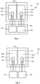
- FIG. 1 is a block diagram that illustrates a sample block assembly according to the prior art.
- the sample block assembly 10 comprises a sample block 11, a pair of Peltier devices 12a and 12b, a thermal sensor 13 and a controller 17.
- the pair of Peltier devices 12a and 12b are electrically connected in series through electrical conduit 16 and electrically connected to the controller 17 through electrical conduits 15.
- the thermal sensor 13 is located in a gap 18 provided between the Peltier devices 12a and 12b, and is electrically connected to the controller 17 through electrical conduits 14. Gap 18 is necessary to provide continuous thermal communication between the sample block 11 and Peltier devices 12a and 12b and between thermal sensor 13 and sample block 11. It should be understood by one skilled in the art that what is depicted in Fig.
- FIG. 1 is not limited to two Peltier devices and may be scaled to apply to any number of Peltier devices. It should be noted that placing thermal sensor 13 in gap region 18 and electrically controlling Peltier devices 12a and 12b in series can be detrimental to achieving good thermal uniformity throughout the sample block. This is due in part to thermal cross interference from the two Peltier devices being simultaneously adjacent to thermal sensor 13 and because electrically controlling the Peltier devices in series does not allow for independent control of the current that is directed to each Peltier to allow for temperature compensation even if temperature non uniformities are detected on the sample block.
- Figure 2 is a block diagram that illustrates a sample block assembly providing independent control of two Peltier devices, in accordance with various embodiments.
- thermal block assembly 20 can be comprised of sample block 21, Peltier devices 22a and 22b, a first sensor 23, a second sensor 24 and a controller 27.
- the configuration shown in Fig. 2 can provide for the independent control of Peltiers 22a and 22b to compensate for temperature non uniformities detected on sample block 21. This can be accomplished by electrically connecting Peltier 22a to controller 27 through electrical conduits 25 and Peltier device 22b to controller 27 through electrical conduits 26.
- Independent control of Peltier devices 22a and 22b to compensate for temperature non uniformities on sample block 21 can be further enabled through placing the first sensor 23 and the second sensor 24 adjacent to Peltiers 12a and 12, respetively.
- First sensor 23 can be electrically connected to controller 27 through electrical conduits 28 and the second sensor 24 can be electrically connected to controller 27 through electrical conduits 29. In this manner the temperature of Peltier device 22a can be dependent on the temperature indicated by first sensor 23, and the temperature of Peltier device 22b can be dependent on the temperature indicated by second sensor 24.
- Figs. 3A, 3B and 3C depict various views of a Peltier device, in accordance with various embodiments.
- Fig. 3A is a top view of Peltier device 30
- Fig. 3B is an isometric view of Peltier device 30
- Fig. 3C is a side view of Peltier device 30.
- One skilled in the art will recognize that the general layout and construction of the Peltier device shown in Fig. 3A, 3B and 3C can be similar to conventional Peltier devices, but with some critical differences (as described below).
- Peltier device 30 can be comprised of a first thermal conducting layer 31, a second thermal conducting layer 34, and a plurality of semiconductor pellets 35 also referred to in the art as Peltier elements sandwiched in between the first 31 and the second 34 conducing layers.
- the second thermal conducting layer 34 can be slightly longer in one dimension than first thermal conducting layer 31 to allow for the connection of wires 33 to provide electrical conduits for connection to controller 17.
- an open channel 32 can be carved out of the first thermal conducting layer 31 and Peltier elements 35 to expose an inner surface 36 of second thermal conducting layer 34.
- open channel 32 can be a groove carved out of an edge surface of the Peltier device.
- open channel 32 can be carved out of the second thermal conducting layer 34 and Peltier elements 35, to expose an inner surface (not depicted) of the first thermal conducting layer 31.
- open channel 32 can further be configured to contain or house a thermal sensor element that can be used to measure a temperature of a region of a sample block positioned adjacent to the thermal sensor.
- the thermal sensor can be integrated into a housing within Peltier device 30.
- the open channel can be sized to accommodate the sensor chosen for a particular application.
- first thermal conducting layer 31 and Peltier elements 35 can adversely impact the TNU across a sample block. This can be caused by the absence of Peltier elements 35 in the region of open channel 32. This potential negative effect on TNU will be discussed later in this disclosure.
- FIG. 4 is a block diagram that illustrates a multi-channel power amplifier system layout used to control the temperature of a sample block assembly, in accordance with various embodiments.
- a multi-channel power amplifier system can be characterized by a controller circuit including multiple electrical circuits or channels.
- each channel can be capable of providing electronic signals such as voltage and/or current to a unique thermoelectric device. That is, one channel can be assigned to one unique thermoelectric device.
- each channel is further capable of being interfaced to a thermal sensor located proximate to (or within) the unique thermoelectric device. The thermal sensor can be configured to convert temperature measurements to an electrical signal that can be read by the controller circuit.
- each unique thermoelectric device is associated with a thermal sensor to form a thermoelectric device control unit that is in communications with a single channel.
- the controller circuit is in communication with an external processor and/or other external computing device capable of executing machine language instructions to provide operational instructions and/or control signals to the controller circuit.
- the processor can be embedded within the controller circuit or located external to the controller circuit but within a common housing with the controller circuit.
- the processor and/or computing device can be in communication with all the channels resident in the controller.
- the processor and/or other computing device can use each channel of the controller to independently control voltage and/or current provided to each unique thermoelectric device based on the electrical signals provided by the thermal sensor associated with the thermoelectric device.
- control of voltage and/or current based on the electrical signal from the sensor represents a closed loop control system.
- the closed loop control system is capable of controlling the temperature of each thermoelectric device independently from each other thereby providing a substantially uniform temperature across the sample block.
- sample block assembly 400 can be comprised of sample block 410 and Peltier devices 420a and 420b.
- Peltier devices 420a and 420b can have substantially the same construction and features as those depicted in Figs. 3A and 3B .
- thermal sensor 430 can be housed or contained in open channel 450 of Peltier device 420a.
- thermal sensor 440 can be housed or contained in open channel 460 of Peltier device 420b.
- controller 490 may have one computer processor or many computer processors.
- the computer processor or processors can be configured to execute machine-code suitable for thermal control of Peltier devices 420a and 420b.
- Controller 490 can further be configured to comprise two independently functional channels 470 and 480. Each channel can be connected to a single processor or each channel can have a dedicated processor. Channel 480 can be electrically connected to Peltier device 420a and associated with thermal sensor 430. Similarly, Channel 470 can be electrically connected to Peltier device 420b and associated with thermal sensor 440.
- the independent channel capability of controller 490 and the housing of thermal sensors 430 and 440 within open channels 450 and 460, respectively, can enable independent temperature control of Peltier devices 420a and 420b. The independence of the control channels can provide the capability to adjust the temperature of each Peltier device so as to ensure the regions of the sample block proximate to each Peltier device are maintained at the same temperature.
- thermal sensor 13 of Fig. 1 and thermal sensors 23 and 24 of Fig. 2 one skilled in the art would recognize that locating the sensors next to the associated Peltier devices would require sufficient space between the Peltier devices to accommodate the sensors.
- the location of thermal sensor 430 in housing 450 (e.g., channel, groove or notch) of Peltier device 420a and thermal sensor 440 in housing 460 (e.g., channel, groove or notch) of Peltier device 420b as depicted in Fig. 4 enables the gap 405 between the Peltier devices to be reduced. The reduction of gap 405 can offer further opportunities to improve thermal uniformity throughout sample block 410.
- FIG. 5 is a block diagram that illustrates a multi-module power amplifier system layout used to control the temperature of a sample block assembly, in accordance with various embodiments.
- a multi-module power amplifier can be differentiated from the multi-channel power amplifier depicted in Fig. 4 .
- a multi-module power amplifier can be characterized as comprising multiple thermal control modules, wherein each module can be capable of providing electronic signals such as voltage and/or current to a thermoelectric device.
- each module is further capable of being interfaced to a thermal sensor located proximate to (or within) a unique to a thermoelectric device. The thermal sensor can be configured to convert temperature measurements to an electrical signal that can be read by the controller circuit.
- each unique thermoelectric device is associated with a thermal sensor to form a thermoelectric device control unit that is in communications with a single thermal control module.
- each module is in communication with a unique processor and/or other computing device capable of executing machine language instructions.
- the unique processor can be embedded in each module or located external to each module.
- the processor can be in communication with a unique thermoelectric device and a unique thermal sensor associated with each module.
- the processor and/or other computing device associated with each module can independently control voltage and/or current to each thermoelectric device based on the electrical signals provided by the unique sensor associated with the thermoelectric device.
- the control of voltage and/or current based on the electrical signal from the sensor represents a closed loop control system capable of controlling the temperature of each thermoelectric device independently from each other thereby providing a substantially uniform temperature across the sample block.
- sample block assembly 500 can be comprised of a sample block 410 and Peltier devices 420a and 420b.
- Fig. 5 further shows thermal sensor 430 can be contained within an open channel 450 of Peltier device 420a.
- thermal sensor 440 is shown contained within open channel 460 of Peltier device 420b.
- sample block assembly 500 can be electrically connected to thermal control modules 570 and 580.
- Peltier device 420a and associated thermal sensor 430 can be electrically connected to independent thermal controller 580
- Peltier device 420b and associated thermal sensor 440 can be electrically connected to independent thermal controller 570.
- independent thermal control modules 570 and 580 can be independent modules each comprising a computer processor capable of executing machine-code suitable for independent thermal control of a Peltier device and associated thermal sensor. Similar to the embodiments depicted in Fig. 4 , the independence of the control modules can provide the capability to individually adjust the temperature of each Peltier device so as to ensure that all the regions of the sample block that is proximate to each Peltier device are maintained at the same temperature.
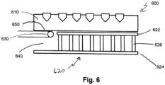
- Fig. 6 is a cross sectional illustration of how a thermal sensor can be placed on a sample block assembly, in accordance with various embodiments.
- sample block assembly 600 comprises sample block 610, thermal sensor 630 and Peltier device 620.
- Fig. 6 further shows the elements of the Peltier device as being comprised of a first thermal conductive layer 622, a second thermal conductive layer 624, thermoelectric pellets 626 and an open channel 640.
- the thermal sensor 630 can be housed in an open channel 640 and proximate to and in thermal communication with sample block region 650.
- the thermal sensor 630 can be housed in a separate and distinct integrated housing (not shown) that is proximate to and in thermal communication with sample block region 650. In various embodiments, the thermal sensor 630 can be integrated (not shown) within Peltier device 620 and proximate to and in thermal communication with thermal conductive layer 622 that is in thermal communication with sample block region 650.
- the thermal block assembly depicted in block diagrams of Figs. 4-6 can also include a heat sink that is in thermal contact with the thermoelectric devices.
- a thermal block assembly is shown in Fig. 7 , which provides a cross sectional schematic of a sample block assembly, in accordance with various embodiments.
- the thermal block assembly 700 comprised of sample block 710, Peltier device 720, open channel 750, thermal sensor 730 and heat sink 740.
- heat sink 740 can further comprise a baseplate 742 and fins 744 extending from the bottom of the baseplate. Heat sink 740 can be in thermal contact with the Peltier device 720 and can contribute to the uniform removal (or dissipation) of heat from the sample block 710.
- Thermal block assembly 700 also shows a location for an edge heater 760.
- an edge heater 760 can be included in a thermal block assembly to counteract the heat flow from a sample block to areas of a lower temperature. Counteracting the heat flow from the sample block can provide an improvement to the TNU performance of the sample block assembly.
- the thermal block assembly can include more than one sample block.
- An example of such a sample block assembly is shown as Fig. 8 which provides a cross sectional illustration of a multi-block sample block assembly and how the various heat sink elements are integrated with the sample block assembly, in accordance with various embodiments.
- sample block assembly 800 can be comprised of sample block 810 and sample block 820.
- Sample block 810 can be in thermal contact with Peltier device 815 and sample block 820 can be in thermal contact with Peltier device 825.
- sample block 810 and 820 and their respective Peltier devices 815 and 825 are also in thermal contact with heat sink 830.
- sample block assembly of Fig. 8 can also have more than one heat sink.
- sample block 810 and 820 and their respective Peltier devices 815 and 825 of sample block assembly 800 can each be in thermal contact with their own individual heat sinks (not shown). That is, sample block assembly 800 can be comprised of two or more sample blocks. Each sample block can be associated with a set of Peltier devices and a heat sink. Such configuration can allow for independent thermal control of each of the sample blocks contained within sample block assembly 800.
- Fig. 9 is a top-view block diagram that illustrates how the individually controlled Peltier devices are positioned underneath a sample block, in accordance with various embodiments.
- thermal block assembly 900 can be comprised of more than one sample block. That is, as depicted, sample block 910 is depicted as being located on top of three Peltier devices (920, 930, 940). While the three Peltier devices are not visible underneath sample block 910, the pairs of electrical connectors 915 that are shown to the left of the sample block 910 depicts the relationship between the sample block 910 and the associated Peltier devices (920, 930, 940). The right side of Fig. 9 shows three Peltier devices 920, 930 and 940.
- Peltiers 920, 930 and 940 are shown without an associated sample block and depicts what would be exposed if sample block 910 was removed. Further, Peltier devices 920, 930 and 940 are arranged such that open channels 925, 935 and 945 are located to the right. Similarly, though not shown, the Peltier devices located under sample block 910 have open channels similar to open channels 925, 935 and 945. In various embodiments a Peltier device can be located under the center region of the sample block, with additional Peltier devices around the outer perimeter of the center Peltier. Such an embodiment can contribute to improving the thermal uniformity of the sample block by providing independent thermal control to the center and each side of the sample block. The open channels in the Peltier devices under sample block 910, however, would be located to the left.
- the independent control of each of the Peltier devices can enable the correction of small temperature variations throughout the sample block.
- Small temperature variations can occur for various reasons including but not limited to mismatched or unmatched Peltier devices, imperfect thermal coupling between the sample block and the Peltier devices, imperfect thermal coupling between the Peltier devices and the heat sink, non-uniform thermal conductivity in the sample block, and non-uniform thermal diffusion of heat into the heat sink.
- the effects of the small variations can be minimized by independently enabling small electrical control adjustments to each Peltier device based on feedback from the thermal sensor (placed within or proximate to each Peltier device) thereby driving small thermal adjustments to provide a substantially uniform temperature throughout the sample block.
- the capability of driving small thermal adjustments to minimize small variations in temperature can also be effective in minimizing differences in thermal uniformity between instruments.
- representative systems of the conventional art typically configure multiple Peltier devices electrically in series. While the series configuration enables the multiple Peltier devices to be subjected to the same electrical current, the series configuration can be prohibitive to independent discrete control of single Peltier elements. Therefore the capability of representative systems of the conventional art can be limited and inhibits small electrical control adjustments to individual Peltier devices that result in small temperature adjustments to provide substantially uniform temperature throughout the sample block.
- thermocycler system 1000 depicts a thermal block assembly 1020 and a thermal control interface 1030 in communications with controller 1010 through communications port 1040.
- controller 1010 is further shown to comprise computer processing unit 1012.
- the computer processing unit 1012 is capable of executing machine instructions contained in computer readable medium 1014.
- Computer processing unit 1012 can be any processor known in the art capable of executing the machine instructions contained in the computer readable medium 1014.
- computer readable medium 1014 can be any type of storage medium known in the art suitable for the application.
- examples of such computer readable storage medium include hard drives, network attached storage (NAS), read-only memory, random-access memory, CD-ROMs, CD-Rs, CD-RWs, magnetic tapes, and other optical, FLASH memory and non-optical data storage devices.
- the computer readable storage medium can also be distributed over network coupled computer systems so that the computer readable code is stored and executed in a distributed fashion.
- FIG 11 is an exemplary process flowchart showing how thermal uniformity can be can be achieved throughout a sample block, in accordance with various embodiments.
- a block assembly is provided.
- the block assembly can include a sample block and two or more thermoelectric devices in thermal communication with the sample block.
- each of the thermoelectric devices can house a unique thermal sensor.
- each of the thermoelectric devices can be paired along with their respective unique thermal sensor to form a unique, physical thermal unit.
- each unique physical thermal unit can be controlled independently as previously presented.
- the independent control capability can be accomplished through the use of various controller configurations including but not limited to multi-channel power amplifiers and multi-module power amplifiers.
- a single channel or module can be used to control a single unique physical thermal unit.
- unique physical thermal units can be combined to form virtual channels.
- Virtual channels can be formed by selectively controlling multiple physical channels or modules to the same temperature setpoint to thermally control multiple thermal units.
- a controller can have six physical channels or modules.
- a six channel or module controller can combine unique physical thermal units into different sized virtual channels capable of providing a substantially uniform temperature across different sized sample blocks.
- six physical channels or modules can be used to provide substantially uniform temperature across a 96 well sample block configured as an 8x12 well rectangular array.
- the six physical channels or modules can be combined to form 2 virtual channels each virtual channel being the combination of 3 adjacent physical channels or modules.
- Such a configuration can provide a substantially uniform temperature across two 48 well sample blocks or two 96 well sample blocks.
- each 48 well sample block can be configured as an 8x6 rectangular well array.
- each 48 well sample block can be configured as 4x12 well rectangular well array.
- the six physical channels or modules can be combined to form three virtual channels. Such a configuration can provide a substantial uniform temperature across three 32 well sample blocks.
- each 32 well sample block can be configured as a 4x8 rectangular well array. It should be understood that the number of physical channels or modules is not limited to six, and that any number of channels or modules either greater than six or less than six are included in the present teachings.
- thermocycler system can include a thermal block assembly and a base unit configured with a controller.
- the thermal block assembly can be removable from the base unit and replaced with a different thermal block assembly.
- Each thermal block assembly can be configured with a different sample block format.
- Sample block formats can be configured with different numbers of sample wells including but not limited to 16 wells, 32 wells, 48 wells, 96 wells or 384 wells.
- the format of the sample block can be encoded in the sample block assembly. Encoding implementations including, but not limited to, hardware jumpers, resistive terminators, pull-up resistors, pull-down resistors or data written to a memory device can provide suitable encoding. In various embodiments the encoded sample block format can be communicated to the base unit and controller or to an externally connected computer device.
- the base unit or external computer device can be capable of decoding the block format communicated from the sample block assembly.
- the base unit or external computer device can be capable of determining what virtual channel configuration corresponds to the sample block format.
- the controller can combine the physical channels of the controller appropriately to result in the required virtual channel configuration.
- the temperature of each of the thermal units can be independently controlled with a controller to maintain a substantially uniform temperature throughout the sample block.
- the controller can be a multi-channel controller, similar to what has previously been described above.
- the controller can be a multi-module controller, also similar to what has been described above.
- TNU as either a difference of about 1.0° C, or an average difference of 0.5° C.
- the TNU values are calculated values based on sample block temperature measurements.
- temperature measurements are acquired from a set of thermal sensors located in specific wells of a sample block.
- the specific well locations of the sensors in the sample block are determined during the design phase of the sample block assembly and can represent the regions of the sample block that are most thermally diverse.
- the temperature measurements are acquired through the use of a protocol (procedure) that can be resident on a hand held device or other computing device either of which is capable of executing machine-code.
- the protocol (procedure) can include thermal cycling parameters such as setpoint temperatures and dwell (hold) times.
- the thermal measurements can be taken during the transition (ramp) from one setpoint temperature to a second setpoint temperature to determine a dynamic TNU.
- the thermal measurements can be taken during the dwell (hold) time to determine a static TNU.
- the protocol (procedure) can include at what point in the dwell (hold) time or transition (ramp) time a measurement would be read.
- a TNU protocol can specify taking temperature measurements while cycling sample block temperatures between 95°C and 60°C.
- the protocol can further specify the measurements being taken 30 seconds after the hold time or dwell time begins. At each temperature and time period all sensors in the fixture are read, and the results are stored in a memory.
- the TNU is then calculated from the temperature readings obtained from the sensors.
- static TNU can be measured 30 seconds after the sample block reaches the setpoint temperature.
- the TNU can then be calculated by subtracting the coolest temperature from the warmest temperature. This method can be referred to as the difference TNU.
- TNU can involve identifying the warmest temperature and the coolest temperature recorded from all the sensors at a specific temperature point, for example 95°C and 60°C.
- static TNU can be measured 30 seconds after the sample block reaches the setpoint temperature.
- the TNU can then be calculated by subtracting the coolest temperature from the warmest temperature, and then dividing the difference by two. This method can be referred to as the average difference TNU.
- the TNU calculated from the sample block temperature measurements is not independent from setpoint temperature. As presented previously, heat loss from the sample block is greater when the temperature difference between the sample block and the ambient temperature is highest. A higher sample block setpoint, therefore, will inherently have a higher TNU. As a result, for example, the calculated TNU at a setpoint of 95°C will be greater than the TNU calculated at a lower temperature, such as 60°C.
- thermal block assemblies can be subject to heat loss from the edges and corners of the sample block. Additionally the inclusion of open channel 32 in Fig. 3 can further result in insufficient and/or non-uniform distribution of heat being supplied throughout a sample block and contribute to a degradation of TNU performance. In various emboidments, this heat loss can be mitigated by including one or more edge heaters as an element of the sample block.
- edge heaters there are several examples of edge heaters commercially available.
- Thermafoil TM Heater Minco Products, Inc., Minneapolis, Minn.
- HEATFLEX Kapton TM Heater Heatron, Inc., Leavenworth, Kans.
- Flexible Heaters Watlow Electric Manufacturing Company, St. Louis, Mo.
- Flexible Heaters Ogden Manufacturing Company, Arlington Heights, Ill.
- the edge heaters can be vulcanized silicone rubber heaters, for example Rubber Heater Assemblies (Minco Products, Inc.), SL-B FlexibleSilicone Rubber Heaters (Chromalox, Inc., Pittsburgh, Pa.), Silicone Rubber Heaters (TransLogic, Inc., Huntington Beach, Calif.), Silicone Rubber Heaters (National Plastic Heater Sensor & Control Co., Scarborough, Ontario, Canada).
- Rubber Heater Assemblies Minco Products, Inc.
- SL-B FlexibleSilicone Rubber Heaters Chromalox, Inc., Pittsburgh, Pa.
- Silicone Rubber Heaters TransLogic, Inc., Huntington Beach, Calif.
- Silicone Rubber Heaters National Plastic Heater Sensor & Control Co., Scarborough, Ontario, Canada.
- the edge heater can be coupled to the edge surface with a variety of pressure sensitive adhesive films. It is desirable to provide uniform thickness and lack of bubbles. Uniform thickness provides uniform contact and uniform heating. Bubbles under the edge heater can cause localized overheating and possible heater burnout. Typically, pressure-sensitive adhesives cure at specified temperature ranges. Examples of pressure-sensitive adhesive films include Minco #10, Minco #12, Minco #19, Minco #17, and Ablefilm 550k (AbleStik Laboratories, Collinso Dominguez, Calif.).
- the edge heater can be coupled to the edge surface with liquid adhesives.
- Liquid adhesives are better suited for curved surfaces than pressure sensitive adhesives.
- Liquid adhesives can include 1-part pastes, 2-part pastes, RTV, epoxies, etc. Bubbles can substantially be avoided by special techniques such as drawing vacuum on the adhesive after mixing, or perforating heaters to permit the bubbles to escape.
- Examples of liquid adhesives include Minco #6, GE #566 (GE Silicones, Wilton, Conn.), Minco 25 #15, Crest 3135 A1B (Lord Chemical, Cary, N.C.).
- the edge heater can be coupled to the edge surface by tape or shrink bands.
- Shrink bands can be constructed of Mylar or Kapton. Instead of an intermediate adhesive layer, the adhesive layer is moved to the top of the pasting heater. Examples of shrink bands and stretch tape include Minco BM3, Minco BK4, and Minco #20.
- the pasting heater can be laminated onto the edge surface, for example by films.
- edge heaters can be mechanically attached to the heating surface.
- an edge heater with eyelets have be attached with a lacing cord, Velcro hooks and loops, metallic fasteners with springs, and independent fasteners with straps.
- the heat supplied by an edge heater can be uniformly distributed or non-uniformly distributed.
- a non-uniform heat distribution can be more effective to compensate for non-uniform heat loss from a sample block to ambient as presented previously.
- the non-uniform heat loss can result from the corners of the sample block losing heat more rapidly than the longer edges of the sample block.
- non-uniform heat distribution can be provided by varying the heat density throughout the edge heater. This technique can, for example, compensate for non-uniform heat loss between the edges of a sample block and the corners as presented above.
- the heat distribution can be such that heat can be applied to specific areas of the block and no heat provided to other areas.
- This technique can, for example, compensate for features or regions of a sample block assembly that can be void of a heat source.
- one or more edge heaters can be used as presented above.
- an edge heater can be affixed to one edge of a sample block.
- An additional edge heater can be affixed to an opposing edge surface or an adjacent edge surface of the sample block or both edge surfaces.
- individual edge heaters can be affixed to any or all four edge surfaces of a rectangular sample block.
- the use of multiple edge heaters can enable independent control of each edge heater to compensate for varying heat loss from the sample block during the execution of a thermal protocol (or procedure).
- Figs. 12 and 13 a set of thermal plots depicts the thermal non-uniformity (TNU) performance profile of a sample block assembly using thermal data measured from a thermal block assembly similar to what is shown in Fig. 8 .
- TNU thermal non-uniformity
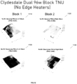
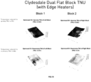
- Fig. 12 is a set of thermal plots depicting the thermal non-uniformity (TNU) performance profile of a dual 96-well sample block assembly without integrated edge heating elements, in accordance with various embodiments.
- the four thermal surface plots shown in Fig. 12 are well known in the art and can be generated through the use of any number of software programs such as Microsoft Excel.
- the surface plots represent the temperature throughout a sample block (without edge heaters) under a specific set of conditions.
- the surface plots of Fig. 12 can represent the thermal profiles of the two sample blocks shown in Fig.8 .
- Surface plots 1110 and 1120 depict the TNU profiles of sample blocks 810 and 820 respectively at an up ramp temperature setting of about 95°C.
- Surface plots 1130 and 1140 represent the TNU of sample blocks 810 and 820 respectively at a down ramp temperature setting of about 60°C.
- the TNU was calculated according to the average difference method discussed above. That is, as shown in the thermal plots of Fig. 12 , the TNU of the sample blocks (without edge heaters) during an up ramp operation to 95°C is between about 0.43°C to about 0.53°C. During a down ramp operation to 60°C, the TNU of the blocks is between about 0.35°C to about 0.46°C.
- Surface plot 1110 shows a slope in temperature on the left side of the plot while Surface plot 1120 shows a slope in temperature on the right side.
- Fig. 9 One skilled in the art, by referring to Fig. 9 , will recognize that the downward slopes shown on surface plots 1110 and 1120 corresponds approximately to the locations of the open channels defined on the Peltier device underneath the sample block. This effect can also be observed in surface plots 1130 and 1140. The effect, however, is not as prominent in surface plots 1130 and 1140, since the temperature difference between the sample block temperature set-point and ambient is much smaller.
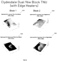
- Fig. 13 is a set of thermal plots depicting the thermal non-uniformity (TNU) performance profile of a dual 96-well sample block assembly with integrated edge heating elements, in accordance with various embodiments.
- Four surface plots 1210, 1220, 1230 and 1240 are depicted in Fig. 13 . Similar to Fig. 12 , surface plots 1210 and 1220 represent the TNU of sample blocks 810 and 820 respectively at an up ramp temperature setting of about 95°C. Surface plots 1230 and 1240 represent the TNU of sample blocks 810 and 820 respectively at a down ramp temperature setting of about 60°C. Similar to the surface plots of Fig. 12 , the TNU for surface plots 1210 through 1240 was also calculated according to the average difference method disclosed previously.
- the surface plots of Fig. 13 are the result of an edge heater being coupled to the substantially flat edge surfaces of sample blocks 810 and 820 of Fig. 8 .
- the coupling of an edge heater to each of blocks 810 and 820 can be accomplished similar to what is shown as edge heater 760 in Fig. 7 .
- the edge heater is configured to provide additional heat to the sample block in the region of the open channels defined on the Peltier devices. The additional heat compensates for the lack of Peltier elements in the open channel, while maintaining the capability of the thermal block assembly to individually control each of the Peltier devices.
- the inclusion of the edge heater has a positive effect for both the TNU at the high temperature and the TNU at the low temperature. Additionally, by comparing the surface plots of Fig. 12 to the surface plots of Fig.13 , one will also recognize that the inclusion of the edge heaters provides an overall improvement to the TNU of both sample blocks.
- the resulting TNUs shown in Fig. 13 is almost a factor of 2 better than the industry standard for the average difference method of 0.5°C that was previously disclosed in Fig. 12 . That is, as shown in the thermal plots of Fig. 13 , the TNU (calculated using an average difference method) of the blocks during an up ramp operation to 95°C is between about 0.26°C and 0.28°C. During a down ramp operation to 60°C, the TNU of the blocks is between about 0.24°C to about 0.29°C.
- Fig. 16 is a set of thermal plots depicting the thermal non-uniformity (TNU) performance profile of a dual 96-well sample block assembly with integrated edge heating elements for a sample block assembly representative of the conventional art.
- Four surface plots 1610, 1620, 1630 and 1640 are depicted in Fig. 16 .
- Surface plots 1610 and 1620 represent the TNU of sample blocks similar to sample blocks 810 and 820 respectively at an up ramp temperature setting of about 95°C.
- Surface plots 1630 and 1640 represent the TNU of sample blocks similar to sample blocks 810 and 820 respectively at a down ramp temperature setting of about 60°C.
- the sample blocks used in creating surface plots 1610 to 1640 differ from sample blocks 810 and 820 of Fig. 8 .
- the sample blocks of Fig. 16 include thermoelectric devices void of open channel 750 of Fig. 7 and are therefore incapable of independent discrete thermal control of the individual thermoelectric devices.. Similar to the surface plots of Fig. 13 , the TNU for surface plots 1610 through 1640 were also calculated according to the average difference method disclosed previously.
- surface plots 1610 through 1640 are the result of an edge heater being coupled to the substantially flat edge surfaces of sample blocks similar to sample blocks 810 and 820 of Fig. 8 .
- the coupling of an edge heater to each of blocks 810 and 820 can be accomplished similar to what is shown as edge heater 760 in Fig. 7 .
- thermoelectric devices with the open channel which enables the capability of independent discrete thermal control of the thermoelectric devices has a positive effect for both the TNU at the high temperature and the TNU at the low temperature.
- the inclusion of the thermoelectric devices with the open channel provides an overall improvement to the TNU of both sample blocks.
- the resulting TNU shown in Fig. 13 shows almost a 45% improvement in TNU as compared to the TNU for the sample blocks of Fig 16 of the conventional art without an open channel in the thermoelectric devices. That is, as shown in the thermal plots of Fig.
- the TNU (calculated using an average difference method) of the blocks during an up ramp operation to 95°C is between about 0.26°C and 0.28°C as compared to the TNU (calculated using an average difference method) of the blocks of Fig. 16 during an up ramp operation to 95°C which is between about 0.47°C and 0.49°C.
- the TNU of the blocks of Fig. 13 is between about 0.24°C to about 0.29°C as compared to the TNU (calculated using an average difference method) of the blocks of Fig. 16 during a down ramp operation to 60°C which is between about 0.41°C and 0.43°C. It should also be noted that the TNU for both Fig. 13 and Fig.
- Fig. 14 is a set of thermal plots depicting the thermal non-uniformity (TNU) performance profile of a dual flat-block sample block assembly without integrated edge heating elements, in accordance with various embodiments.
- TNU thermal non-uniformity
- Fig. 15 is a set of thermal plots depicting the thermal non-uniformity (TNU) performance profile of a dual flat-block sample block assembly with integrated edge heating elements, in accordance with various embodiments.
- TNU thermal non-uniformity
Claims (3)
- Thermoblockanordnung (400, 500, 600, 900), umfassend:einen Probenblock (410, 610, 910) mit einer oberen Oberfläche, die konfiguriert ist, um eine Vielzahl von Reaktionsgefäßen aufzunehmen, und einer gegenüberliegenden unteren Oberfläche; undzwei oder mehr thermoelektrische Vorrichtungen (420a, 420b, 620, 920, 939, 940), die mit dem Probenblock betriebsfähig gekoppelt sind, wobei jede thermoelektrische Vorrichtung ein Gehäuse (450, 460, 640, 925, 935, 945) für einen Thermosensor (430, 440, 630) und eine Thermosteuerschnittstelle (1030) in Kommunikation mit einer Steuerung (1010) einschließt, wobei jede thermoelektrische Vorrichtung eine konfiguriert ist, um unabhängig voneinander in Betrieb zu sein, um ein im Wesentlichen gleichmäßiges Temperaturprofil in dem gesamten Probenblock bereitzustellen, wobei jede der thermoelektrischen Vorrichtungen ferner eine obere Oberfläche in Thermokontakt mit der unteren Oberfläche des Probenblocks und eine gegenüberliegende untere Oberfläche, die dem Probenblock abgewandt ist, umfasst, wobei das Gehäuse eine Nut ist, die aus einer Kantenoberfläche jeder thermoelektrischen Vorrichtung herausgearbeitet ist, und wobei jede der thermoelektrischen Vorrichtungen einen eindeutigen Thermosensor unterbringt.
- Thermoblockanordnung nach Anspruch 1, wobei die obere Oberfläche die Nut umfasst.
- Thermoblockanordnung nach Anspruch 1, wobei die untere Oberfläche die Nut umfasst.
Applications Claiming Priority (2)
| Application Number | Priority Date | Filing Date | Title |
|---|---|---|---|
| US201361878464P | 2013-09-16 | 2013-09-16 | |
| PCT/US2014/055615 WO2015039014A1 (en) | 2013-09-16 | 2014-09-15 | Apparatuses, systems and methods for providing thermocycler thermal uniformity |
Publications (2)
| Publication Number | Publication Date |
|---|---|
| EP3046671A1 EP3046671A1 (de) | 2016-07-27 |
| EP3046671B1 true EP3046671B1 (de) | 2023-04-12 |
Family
ID=51656080
Family Applications (1)
| Application Number | Title | Priority Date | Filing Date |
|---|---|---|---|
| EP14777985.4A Active EP3046671B1 (de) | 2013-09-16 | 2014-09-15 | Vorrichtung zur herstellung eines gleichmässigen temperaturverlaufs für einen thermocycler |
Country Status (9)
| Country | Link |
|---|---|
| US (2) | US20160214110A1 (de) |
| EP (1) | EP3046671B1 (de) |
| JP (1) | JP6655539B2 (de) |
| KR (1) | KR20160055248A (de) |
| CN (2) | CN204625602U (de) |
| CA (1) | CA2922854A1 (de) |
| MX (1) | MX2016003395A (de) |
| SG (1) | SG11201601275UA (de) |
| WO (1) | WO2015039014A1 (de) |
Families Citing this family (14)
| Publication number | Priority date | Publication date | Assignee | Title |
|---|---|---|---|---|
| US20160214110A1 (en) | 2013-09-16 | 2016-07-28 | Life Technologies Corporation | Apparatuses, Systems and Methods for Providing Thermocycler Thermal Uniformity |
| KR20160123356A (ko) | 2014-02-18 | 2016-10-25 | 라이프 테크놀로지스 코포레이션 | 스케일러블 유전자증폭기를 제공하고 열전 장치를 격리시키기 위한 장치, 시스템 및 방법 |
| GB2531260B (en) * | 2014-10-13 | 2019-08-14 | Bae Systems Plc | Peltier effect heat transfer system |
| CA2992978C (en) * | 2015-07-23 | 2023-09-19 | Cepheid | Thermal control device and methods of use |
| US11583862B2 (en) | 2015-09-15 | 2023-02-21 | Life Technologies Corporation | Systems and methods for biological analysis |
| EP3349902B1 (de) * | 2015-09-15 | 2021-05-26 | Life Technologies Corporation | System zur biologischen analyse |
| KR102046943B1 (ko) * | 2017-04-19 | 2019-11-20 | 주식회사 넥서스비 | 휴대용 실시간 pcr 측정기기 |
| KR102022198B1 (ko) * | 2018-09-17 | 2019-09-18 | 서강대학교산학협력단 | 플라즈몬 가열 및 온도 산출 시스템 및 그 방법 |
| US20220184612A1 (en) * | 2019-03-18 | 2022-06-16 | Seegene, Inc. | Thermal cycler comprising sample holder assembly |
| CN111575470B (zh) * | 2020-06-28 | 2021-01-15 | 西北工业大学 | 一种棒状材料连续温度梯度热处理装置和方法 |
| GB2599463A (en) * | 2020-10-05 | 2022-04-06 | James Wyllie Nicholas | Improvements relating to thermoelectric coolers, thermoelectric generators & thermoelectric assemblies |
| GB2621263A (en) * | 2020-10-05 | 2024-02-07 | James Wyllie Nicholas | Improvements relating to thermoelectric coolers, thermoelectric generators & thermoelectric assemblies |
| GB2599645B (en) * | 2020-10-05 | 2022-10-26 | James Wyllie Nicholas | Improvements relating to thermoelectric coolers, thermoelectric generators & thermoelectric assemblies |
| CN114400211A (zh) * | 2022-01-17 | 2022-04-26 | 长鑫存储技术有限公司 | 一种半导体结构及其形成方法 |
Family Cites Families (85)
| Publication number | Priority date | Publication date | Assignee | Title |
|---|---|---|---|---|
| US3036893A (en) | 1960-03-14 | 1962-05-29 | Scientific Industries | Automatic chemical analyzer |
| US3260413A (en) | 1964-08-31 | 1966-07-12 | Scientific Industries | Automatic chemical analyzer |
| US3216804A (en) | 1962-01-31 | 1965-11-09 | Scientific Industries | Automatic chemical analyzer and sample dispenser |
| US3128239A (en) | 1962-06-29 | 1964-04-07 | Robert Z Page | Biological detection equipment |
| US3261668A (en) | 1962-08-14 | 1966-07-19 | Scientific Industries | Chemical analyzer tape |
| US3271112A (en) | 1962-12-12 | 1966-09-06 | Donald L Williams | Apparatus for laboratory testing |
| US3368872A (en) | 1964-08-31 | 1968-02-13 | Scientific Industries | Automatic chemical analyzer |
| DE3265723D1 (en) | 1982-03-18 | 1985-10-03 | Turgut Koruk | Quantized (digital) heating plate |
| US5333675C1 (en) | 1986-02-25 | 2001-05-01 | Perkin Elmer Corp | Apparatus and method for performing automated amplification of nucleic acid sequences and assays using heating and cooling steps |
| US5656493A (en) | 1985-03-28 | 1997-08-12 | The Perkin-Elmer Corporation | System for automated performance of the polymerase chain reaction |
| US5038852A (en) | 1986-02-25 | 1991-08-13 | Cetus Corporation | Apparatus and method for performing automated amplification of nucleic acid sequences and assays using heating and cooling steps |
| CA1339653C (en) | 1986-02-25 | 1998-02-03 | Larry J. Johnson | Appartus and method for performing automated amplification of nucleic acid sequences and assays using heating and cooling steps |
| EP0342155A3 (de) | 1988-05-13 | 1990-06-27 | Agrogen-Stiftung | Laboratoriumsgerät zum wahlweisen Heizen und Kühlen |
| GB8814962D0 (en) | 1988-06-23 | 1988-07-27 | Lep Scient Ltd | Biochemical reaction machine |
| US4865986A (en) | 1988-10-06 | 1989-09-12 | Coy Corporation | Temperature control apparatus |
| DE8814398U1 (de) | 1988-11-17 | 1989-02-16 | Max-Planck-Gesellschaft Zur Foerderung Der Wissenschaften Ev, 3400 Goettingen, De | |
| US4950608A (en) | 1989-04-25 | 1990-08-21 | Scinics Co., Ltd. | Temperature regulating container |
| US5504007A (en) | 1989-05-19 | 1996-04-02 | Becton, Dickinson And Company | Rapid thermal cycle apparatus |
| DE4029004C1 (de) | 1990-09-13 | 1992-04-02 | Max-Planck-Gesellschaft Zur Foerderung Der Wissenschaften Ev, 3400 Goettingen, De | |
| KR100236506B1 (ko) | 1990-11-29 | 2000-01-15 | 퍼킨-엘머시터스인스트루먼츠 | 폴리머라제 연쇄 반응 수행 장치 |
| US6703236B2 (en) | 1990-11-29 | 2004-03-09 | Applera Corporation | Thermal cycler for automatic performance of the polymerase chain reaction with close temperature control |
| US5994056A (en) | 1991-05-02 | 1999-11-30 | Roche Molecular Systems, Inc. | Homogeneous methods for nucleic acid amplification and detection |
| FI915731A0 (fi) | 1991-12-05 | 1991-12-05 | Derek Henry Potter | Foerfarande och anordning foer reglering av temperaturen i ett flertal prov. |
| DE4234086A1 (de) | 1992-02-05 | 1993-08-12 | Diagen Inst Molekularbio | Verfahren zur bestimmung von in vitro amplifizierten nukleinsaeuresequenzen |
| US5601141A (en) * | 1992-10-13 | 1997-02-11 | Intelligent Automation Systems, Inc. | High throughput thermal cycler |
| US5441576A (en) | 1993-02-01 | 1995-08-15 | Bierschenk; James L. | Thermoelectric cooler |
| CA2130517C (en) | 1993-09-10 | 1999-10-05 | Walter Fassbind | Array of reaction containers for an apparatus for automatic performance of temperature cycles |
| US5525300A (en) | 1993-10-20 | 1996-06-11 | Stratagene | Thermal cycler including a temperature gradient block |
| DE4435107C1 (de) | 1994-09-30 | 1996-04-04 | Biometra Biomedizinische Analy | Miniaturisierter Fluß-Thermocycler |
| US20020068357A1 (en) | 1995-09-28 | 2002-06-06 | Mathies Richard A. | Miniaturized integrated nucleic acid processing and analysis device and method |
| US6825047B1 (en) | 1996-04-03 | 2004-11-30 | Applera Corporation | Device and method for multiple analyte detection |
| US5802856A (en) | 1996-07-31 | 1998-09-08 | Stanford University | Multizone bake/chill thermal cycling module |
| DE19646115C2 (de) | 1996-11-08 | 2000-05-25 | Eppendorf Geraetebau Netheler | Verwendung von Temperiereinrichtungen zur Temperierung eines Temperierblockes |
| DE29623597U1 (de) | 1996-11-08 | 1999-01-07 | Eppendorf Geraetebau Netheler | Temperierblock mit Temperiereinrichtungen |
| EP2090366B1 (de) | 1997-03-28 | 2012-12-19 | Life Technologies Corporation | Verbesserungen in einer thermischen Schaltung für PCR |
| US5874667A (en) * | 1997-06-27 | 1999-02-23 | Kasman; David H. | Block-type heater assembly for isothermally heating samples with observation access |
| US6106784A (en) | 1997-09-26 | 2000-08-22 | Applied Chemical & Engineering Systems, Inc. | Thawing station |
| US6558947B1 (en) | 1997-09-26 | 2003-05-06 | Applied Chemical & Engineering Systems, Inc. | Thermal cycler |
| AU9786798A (en) | 1997-10-10 | 1999-05-03 | Biosepra Inc. | Aligned multiwell multiplate stack and method for processing biological/chemicalsamples using the same |
| US7188001B2 (en) | 1998-03-23 | 2007-03-06 | Cepheid | System and method for temperature control |
| US6093370A (en) | 1998-06-11 | 2000-07-25 | Hitachi, Ltd. | Polynucleotide separation method and apparatus therefor |
| JP2000102376A (ja) * | 1998-09-30 | 2000-04-11 | Sanyo Electric Co Ltd | インキュベータの温度制御装置 |
| US6337435B1 (en) * | 1999-07-30 | 2002-01-08 | Bio-Rad Laboratories, Inc. | Temperature control for multi-vessel reaction apparatus |
| US6633785B1 (en) | 1999-08-31 | 2003-10-14 | Kabushiki Kaisha Toshiba | Thermal cycler and DNA amplifier method |
| DE29917313U1 (de) | 1999-10-01 | 2001-02-15 | Mwg Biotech Ag | Vorrichtung zur Durchführung chemischer oder biologischer Reaktionen |
| JP4457331B2 (ja) * | 2000-03-31 | 2010-04-28 | エイブル株式会社 | 振とう培養機及び培養液の計測または制御方法 |
| US6720187B2 (en) * | 2000-06-28 | 2004-04-13 | 3M Innovative Properties Company | Multi-format sample processing devices |
| GB2366628B (en) | 2000-09-11 | 2002-09-18 | Bookham Technology Plc | Method and apparatus for temperature control |
| US7727479B2 (en) | 2000-09-29 | 2010-06-01 | Applied Biosystems, Llc | Device for the carrying out of chemical or biological reactions |
| JP2002355038A (ja) | 2001-03-29 | 2002-12-10 | Japan Science & Technology Corp | 遺伝子解析方法およびその解析装置 |
| DE10221763A1 (de) | 2002-05-15 | 2003-12-04 | Eppendorf Ag | Thermocycler mit in Cyclen angesteuertem Temperierblock |
| JP3980966B2 (ja) | 2002-08-21 | 2007-09-26 | シャープ株式会社 | プレゼンテーション用表示装置 |
| US6730883B2 (en) | 2002-10-02 | 2004-05-04 | Stratagene | Flexible heating cover assembly for thermal cycling of samples of biological material |
| DE20218574U1 (de) | 2002-11-30 | 2003-12-11 | Element-System Rudolf Bohnacker Gmbh | Trägersystem für Regalelemente |
| US8676383B2 (en) | 2002-12-23 | 2014-03-18 | Applied Biosystems, Llc | Device for carrying out chemical or biological reactions |
| EP1641563B1 (de) * | 2003-05-23 | 2018-08-29 | Bio-Rad Laboratories, Inc. | Lokalisierte temperaturregelung für raumanordnungen von reaktionsmedien |
| US20040241048A1 (en) | 2003-05-30 | 2004-12-02 | Applera Corporation | Thermal cycling apparatus and method for providing thermal uniformity |
| US7122799B2 (en) | 2003-12-18 | 2006-10-17 | Palo Alto Research Center Incorporated | LED or laser enabled real-time PCR system and spectrophotometer |
| US20050194367A1 (en) | 2004-03-02 | 2005-09-08 | Fredrick William G.Jr. | System and method for remote controlled actuation of laser processing head |
| US7694694B2 (en) * | 2004-05-10 | 2010-04-13 | The Aerospace Corporation | Phase-change valve apparatuses |
| WO2006002403A1 (en) | 2004-06-23 | 2006-01-05 | Applera Corporation | Thermal cycler |
| US7585663B2 (en) | 2004-08-26 | 2009-09-08 | Applied Biosystems, Llc | Thermal device, system, and method, for fluid processing device |
| US7303450B2 (en) | 2005-09-06 | 2007-12-04 | Lear Corporation | Electrical terminal assembly |
| JP2009537152A (ja) | 2006-05-17 | 2009-10-29 | カリフォルニア インスティテュート オブ テクノロジー | 温度サイクルシステム |
| WO2007146443A2 (en) * | 2006-06-14 | 2007-12-21 | Oldenburg Kevin R Ph D | Thermal-cycling devices and methods of using the same |
| US20080087316A1 (en) | 2006-10-12 | 2008-04-17 | Masa Inaba | Thermoelectric device with internal sensor |
| DE102007003754A1 (de) * | 2007-01-19 | 2008-07-24 | Eppendorf Ag | Temperiervorrichtung mit Kalibrierungseinrichtung |
| US20080176292A1 (en) | 2007-01-23 | 2008-07-24 | Texas A&M University System | Portable buoyancy driven pcr thermocycler |
| WO2008116184A1 (en) | 2007-03-21 | 2008-09-25 | Applera Corporation | Adaptive thermal block temperature control method and system |
| US9170060B2 (en) | 2008-01-22 | 2015-10-27 | Lawrence Livermore National Security, Llc | Rapid microfluidic thermal cycler for nucleic acid amplification |
| US8586794B2 (en) | 2008-07-25 | 2013-11-19 | Basf Se | 5-isopropyl-3-aminomethyl-2-methyl-1-amino-cyclohexane (carvone diamine), and method for the production thereof |
| EP2153901A1 (de) | 2008-08-01 | 2010-02-17 | Eppendorf Ag | Temperierungsvorrichtung mit Testmöglichkeit und Verfahren zum Testen einer Temperierungsvorrichtung |
| US20100081191A1 (en) | 2008-09-26 | 2010-04-01 | Marlow Industries, Inc. | Anisotropic heat spreader for use with a thermoelectric device |
| US20100124766A1 (en) | 2008-11-14 | 2010-05-20 | Life Technologies Corporation | Apparatus and Method for Segmented Thermal Cycler |
| CN102341691A (zh) * | 2008-12-31 | 2012-02-01 | 尹特根埃克斯有限公司 | 具有微流体芯片的仪器 |
| CN102483642B (zh) * | 2009-09-01 | 2014-12-24 | 生命科技公司 | 为快速热循环提供低热不均匀的热块组件和仪器 |
| GB201005704D0 (en) | 2010-04-06 | 2010-05-19 | It Is Internat Ltd | Improvements in systems for chemical and/or biochemical reactions |
| SG184539A1 (en) | 2010-04-09 | 2012-11-29 | Life Technologies Corp | Improved thermal uniformity for thermal cycler instrumentation using dynamic control |
| JP5867668B2 (ja) | 2010-12-01 | 2016-02-24 | セイコーエプソン株式会社 | 熱サイクル装置及び熱サイクル方法 |
| WO2012080746A1 (en) * | 2010-12-17 | 2012-06-21 | Ian Gunter | Methods and systems for fast pcr heating |
| JP5687514B2 (ja) * | 2011-02-17 | 2015-03-18 | 株式会社日立ハイテクノロジーズ | 核酸配列解析装置 |
| US20130157376A1 (en) * | 2011-12-20 | 2013-06-20 | Idaho Technology, Inc. | Thermal Cycler Calibration Device and Related Methods |
| US10928321B2 (en) | 2012-03-09 | 2021-02-23 | Ubiquitome Limited | Portable device for detecting molecule(s) |
| US20160214110A1 (en) | 2013-09-16 | 2016-07-28 | Life Technologies Corporation | Apparatuses, Systems and Methods for Providing Thermocycler Thermal Uniformity |
| KR20160123356A (ko) | 2014-02-18 | 2016-10-25 | 라이프 테크놀로지스 코포레이션 | 스케일러블 유전자증폭기를 제공하고 열전 장치를 격리시키기 위한 장치, 시스템 및 방법 |
-
2014
- 2014-09-15 US US14/917,400 patent/US20160214110A1/en not_active Abandoned
- 2014-09-15 CN CN201420529430.8U patent/CN204625602U/zh active Active
- 2014-09-15 CA CA2922854A patent/CA2922854A1/en not_active Abandoned
- 2014-09-15 JP JP2016542850A patent/JP6655539B2/ja active Active
- 2014-09-15 KR KR1020167009569A patent/KR20160055248A/ko not_active Application Discontinuation
- 2014-09-15 WO PCT/US2014/055615 patent/WO2015039014A1/en active Application Filing
- 2014-09-15 CN CN201480051097.7A patent/CN105813754B/zh active Active
- 2014-09-15 MX MX2016003395A patent/MX2016003395A/es unknown
- 2014-09-15 EP EP14777985.4A patent/EP3046671B1/de active Active
- 2014-09-15 SG SG11201601275UA patent/SG11201601275UA/en unknown
-
2017
- 2017-06-30 US US15/640,241 patent/US10835901B2/en active Active
Also Published As
| Publication number | Publication date |
|---|---|
| KR20160055248A (ko) | 2016-05-17 |
| CN105813754A (zh) | 2016-07-27 |
| WO2015039014A1 (en) | 2015-03-19 |
| MX2016003395A (es) | 2016-06-24 |
| EP3046671A1 (de) | 2016-07-27 |
| US10835901B2 (en) | 2020-11-17 |
| JP6655539B2 (ja) | 2020-02-26 |
| JP2016539657A (ja) | 2016-12-22 |
| US20180056296A1 (en) | 2018-03-01 |
| US20160214110A1 (en) | 2016-07-28 |
| CA2922854A1 (en) | 2015-03-19 |
| CN105813754B (zh) | 2018-12-14 |
| SG11201601275UA (en) | 2016-04-28 |
| CN204625602U (zh) | 2015-09-09 |
Similar Documents
| Publication | Publication Date | Title |
|---|---|---|
| EP3046671B1 (de) | Vorrichtung zur herstellung eines gleichmässigen temperaturverlaufs für einen thermocycler | |
| US20200101461A1 (en) | Apparatuses, systems and methods for providing scalable thermal cyclers and isolating thermoelectric devices | |
| US11073310B2 (en) | Thermal control device and methods of use | |
| AU736484B2 (en) | Improvements in thermal cycler for PCR | |
| EP2339320B1 (de) | Temperaturregler für kleine Flüssigkeitsproben mit unterschiedlichen Wärmekapazitäten | |
| US10391499B2 (en) | Thermal cycling | |
| CN112912721A (zh) | 高样本通量差示扫描量热仪 | |
| EP1386666B1 (de) | Thermo-Zyklus-Vorrichtung zur Ausführung der Polymerase-Kettenreaktion |
Legal Events
| Date | Code | Title | Description |
|---|---|---|---|
| PUAI | Public reference made under article 153(3) epc to a published international application that has entered the european phase |
Free format text: ORIGINAL CODE: 0009012 |
|
| 17P | Request for examination filed |
Effective date: 20160414 |
|
| AK | Designated contracting states |
Kind code of ref document: A1 Designated state(s): AL AT BE BG CH CY CZ DE DK EE ES FI FR GB GR HR HU IE IS IT LI LT LU LV MC MK MT NL NO PL PT RO RS SE SI SK SM TR |
|
| AX | Request for extension of the european patent |
Extension state: BA ME |
|
| RAP1 | Party data changed (applicant data changed or rights of an application transferred) |
Owner name: LIFE TECHNOLOGIES CORPORATION |
|
| DAX | Request for extension of the european patent (deleted) | ||
| STAA | Information on the status of an ep patent application or granted ep patent |
Free format text: STATUS: EXAMINATION IS IN PROGRESS |
|
| 17Q | First examination report despatched |
Effective date: 20190410 |
|
| STAA | Information on the status of an ep patent application or granted ep patent |
Free format text: STATUS: EXAMINATION IS IN PROGRESS |
|
| GRAP | Despatch of communication of intention to grant a patent |
Free format text: ORIGINAL CODE: EPIDOSNIGR1 |
|
| STAA | Information on the status of an ep patent application or granted ep patent |
Free format text: STATUS: GRANT OF PATENT IS INTENDED |
|
| INTG | Intention to grant announced |
Effective date: 20221028 |
|
| GRAS | Grant fee paid |
Free format text: ORIGINAL CODE: EPIDOSNIGR3 |
|
| GRAA | (expected) grant |
Free format text: ORIGINAL CODE: 0009210 |
|
| STAA | Information on the status of an ep patent application or granted ep patent |
Free format text: STATUS: THE PATENT HAS BEEN GRANTED |
|
| AK | Designated contracting states |
Kind code of ref document: B1 Designated state(s): AL AT BE BG CH CY CZ DE DK EE ES FI FR GB GR HR HU IE IS IT LI LT LU LV MC MK MT NL NO PL PT RO RS SE SI SK SM TR |
|
| REG | Reference to a national code |
Ref country code: GB Ref legal event code: FG4D |
|
| REG | Reference to a national code |
Ref country code: CH Ref legal event code: EP |
|
| REG | Reference to a national code |
Ref country code: DE Ref legal event code: R096 Ref document number: 602014086684 Country of ref document: DE |
|
| REG | Reference to a national code |
Ref country code: IE Ref legal event code: FG4D |
|
| REG | Reference to a national code |
Ref country code: AT Ref legal event code: REF Ref document number: 1559478 Country of ref document: AT Kind code of ref document: T Effective date: 20230515 |
|
| REG | Reference to a national code |
Ref country code: LT Ref legal event code: MG9D |
|
| REG | Reference to a national code |
Ref country code: NL Ref legal event code: MP Effective date: 20230412 |
|
| P01 | Opt-out of the competence of the unified patent court (upc) registered |
Effective date: 20230727 |
|
| REG | Reference to a national code |
Ref country code: AT Ref legal event code: MK05 Ref document number: 1559478 Country of ref document: AT Kind code of ref document: T Effective date: 20230412 |
|
| PG25 | Lapsed in a contracting state [announced via postgrant information from national office to epo] |
Ref country code: NL Free format text: LAPSE BECAUSE OF FAILURE TO SUBMIT A TRANSLATION OF THE DESCRIPTION OR TO PAY THE FEE WITHIN THE PRESCRIBED TIME-LIMIT Effective date: 20230412 |
|
| PG25 | Lapsed in a contracting state [announced via postgrant information from national office to epo] |
Ref country code: SE Free format text: LAPSE BECAUSE OF FAILURE TO SUBMIT A TRANSLATION OF THE DESCRIPTION OR TO PAY THE FEE WITHIN THE PRESCRIBED TIME-LIMIT Effective date: 20230412 Ref country code: PT Free format text: LAPSE BECAUSE OF FAILURE TO SUBMIT A TRANSLATION OF THE DESCRIPTION OR TO PAY THE FEE WITHIN THE PRESCRIBED TIME-LIMIT Effective date: 20230814 Ref country code: NO Free format text: LAPSE BECAUSE OF FAILURE TO SUBMIT A TRANSLATION OF THE DESCRIPTION OR TO PAY THE FEE WITHIN THE PRESCRIBED TIME-LIMIT Effective date: 20230712 Ref country code: ES Free format text: LAPSE BECAUSE OF FAILURE TO SUBMIT A TRANSLATION OF THE DESCRIPTION OR TO PAY THE FEE WITHIN THE PRESCRIBED TIME-LIMIT Effective date: 20230412 Ref country code: AT Free format text: LAPSE BECAUSE OF FAILURE TO SUBMIT A TRANSLATION OF THE DESCRIPTION OR TO PAY THE FEE WITHIN THE PRESCRIBED TIME-LIMIT Effective date: 20230412 |
|
| PGFP | Annual fee paid to national office [announced via postgrant information from national office to epo] |
Ref country code: GB Payment date: 20230928 Year of fee payment: 10 |
|
| PG25 | Lapsed in a contracting state [announced via postgrant information from national office to epo] |
Ref country code: RS Free format text: LAPSE BECAUSE OF FAILURE TO SUBMIT A TRANSLATION OF THE DESCRIPTION OR TO PAY THE FEE WITHIN THE PRESCRIBED TIME-LIMIT Effective date: 20230412 Ref country code: PL Free format text: LAPSE BECAUSE OF FAILURE TO SUBMIT A TRANSLATION OF THE DESCRIPTION OR TO PAY THE FEE WITHIN THE PRESCRIBED TIME-LIMIT Effective date: 20230412 Ref country code: LV Free format text: LAPSE BECAUSE OF FAILURE TO SUBMIT A TRANSLATION OF THE DESCRIPTION OR TO PAY THE FEE WITHIN THE PRESCRIBED TIME-LIMIT Effective date: 20230412 Ref country code: LT Free format text: LAPSE BECAUSE OF FAILURE TO SUBMIT A TRANSLATION OF THE DESCRIPTION OR TO PAY THE FEE WITHIN THE PRESCRIBED TIME-LIMIT Effective date: 20230412 Ref country code: IS Free format text: LAPSE BECAUSE OF FAILURE TO SUBMIT A TRANSLATION OF THE DESCRIPTION OR TO PAY THE FEE WITHIN THE PRESCRIBED TIME-LIMIT Effective date: 20230812 Ref country code: HR Free format text: LAPSE BECAUSE OF FAILURE TO SUBMIT A TRANSLATION OF THE DESCRIPTION OR TO PAY THE FEE WITHIN THE PRESCRIBED TIME-LIMIT Effective date: 20230412 Ref country code: GR Free format text: LAPSE BECAUSE OF FAILURE TO SUBMIT A TRANSLATION OF THE DESCRIPTION OR TO PAY THE FEE WITHIN THE PRESCRIBED TIME-LIMIT Effective date: 20230713 Ref country code: AL Free format text: LAPSE BECAUSE OF FAILURE TO SUBMIT A TRANSLATION OF THE DESCRIPTION OR TO PAY THE FEE WITHIN THE PRESCRIBED TIME-LIMIT Effective date: 20230412 |
|
| PGFP | Annual fee paid to national office [announced via postgrant information from national office to epo] |
Ref country code: FR Payment date: 20230926 Year of fee payment: 10 Ref country code: DE Payment date: 20230921 Year of fee payment: 10 |
|
| PG25 | Lapsed in a contracting state [announced via postgrant information from national office to epo] |
Ref country code: FI Free format text: LAPSE BECAUSE OF FAILURE TO SUBMIT A TRANSLATION OF THE DESCRIPTION OR TO PAY THE FEE WITHIN THE PRESCRIBED TIME-LIMIT Effective date: 20230412 |
|
| REG | Reference to a national code |
Ref country code: DE Ref legal event code: R097 Ref document number: 602014086684 Country of ref document: DE |
|
| PG25 | Lapsed in a contracting state [announced via postgrant information from national office to epo] |
Ref country code: SK Free format text: LAPSE BECAUSE OF FAILURE TO SUBMIT A TRANSLATION OF THE DESCRIPTION OR TO PAY THE FEE WITHIN THE PRESCRIBED TIME-LIMIT Effective date: 20230412 |
|
| PG25 | Lapsed in a contracting state [announced via postgrant information from national office to epo] |
Ref country code: SM Free format text: LAPSE BECAUSE OF FAILURE TO SUBMIT A TRANSLATION OF THE DESCRIPTION OR TO PAY THE FEE WITHIN THE PRESCRIBED TIME-LIMIT Effective date: 20230412 Ref country code: SK Free format text: LAPSE BECAUSE OF FAILURE TO SUBMIT A TRANSLATION OF THE DESCRIPTION OR TO PAY THE FEE WITHIN THE PRESCRIBED TIME-LIMIT Effective date: 20230412 Ref country code: RO Free format text: LAPSE BECAUSE OF FAILURE TO SUBMIT A TRANSLATION OF THE DESCRIPTION OR TO PAY THE FEE WITHIN THE PRESCRIBED TIME-LIMIT Effective date: 20230412 Ref country code: EE Free format text: LAPSE BECAUSE OF FAILURE TO SUBMIT A TRANSLATION OF THE DESCRIPTION OR TO PAY THE FEE WITHIN THE PRESCRIBED TIME-LIMIT Effective date: 20230412 Ref country code: DK Free format text: LAPSE BECAUSE OF FAILURE TO SUBMIT A TRANSLATION OF THE DESCRIPTION OR TO PAY THE FEE WITHIN THE PRESCRIBED TIME-LIMIT Effective date: 20230412 Ref country code: CZ Free format text: LAPSE BECAUSE OF FAILURE TO SUBMIT A TRANSLATION OF THE DESCRIPTION OR TO PAY THE FEE WITHIN THE PRESCRIBED TIME-LIMIT Effective date: 20230412 |
|
| PLBE | No opposition filed within time limit |
Free format text: ORIGINAL CODE: 0009261 |
|
| STAA | Information on the status of an ep patent application or granted ep patent |
Free format text: STATUS: NO OPPOSITION FILED WITHIN TIME LIMIT |
|
| 26N | No opposition filed |
Effective date: 20240115 |
|
| REG | Reference to a national code |
Ref country code: CH Ref legal event code: PL |
|
| PG25 | Lapsed in a contracting state [announced via postgrant information from national office to epo] |
Ref country code: SI Free format text: LAPSE BECAUSE OF FAILURE TO SUBMIT A TRANSLATION OF THE DESCRIPTION OR TO PAY THE FEE WITHIN THE PRESCRIBED TIME-LIMIT Effective date: 20230412 |