EP3046377B1 - Procédé pour déterminer une heure de transmission en liaison montante d'un terminal configuré pour une pluralité de cellules dans un système de communications sans fil, et appareil utilisant le procédé - Google Patents
Procédé pour déterminer une heure de transmission en liaison montante d'un terminal configuré pour une pluralité de cellules dans un système de communications sans fil, et appareil utilisant le procédé Download PDFInfo
- Publication number
- EP3046377B1 EP3046377B1 EP14843461.6A EP14843461A EP3046377B1 EP 3046377 B1 EP3046377 B1 EP 3046377B1 EP 14843461 A EP14843461 A EP 14843461A EP 3046377 B1 EP3046377 B1 EP 3046377B1
- Authority
- EP
- European Patent Office
- Prior art keywords
- cell
- downlink
- pucch
- subframe
- uplink
- Prior art date
- Legal status (The legal status is an assumption and is not a legal conclusion. Google has not performed a legal analysis and makes no representation as to the accuracy of the status listed.)
- Active
Links
- 230000005540 biological transmission Effects 0.000 title claims description 71
- 238000000034 method Methods 0.000 title claims description 51
- 238000004891 communication Methods 0.000 title claims description 15
- 230000002776 aggregation Effects 0.000 description 28
- 238000004220 aggregation Methods 0.000 description 28
- 230000032258 transport Effects 0.000 description 26
- 238000013468 resource allocation Methods 0.000 description 20
- 230000008569 process Effects 0.000 description 15
- 238000012544 monitoring process Methods 0.000 description 12
- 230000007480 spreading Effects 0.000 description 9
- 238000003892 spreading Methods 0.000 description 9
- 239000013256 coordination polymer Substances 0.000 description 8
- 125000004122 cyclic group Chemical group 0.000 description 7
- 238000009482 thermal adhesion granulation Methods 0.000 description 7
- 101150071746 Pbsn gene Proteins 0.000 description 6
- 230000011664 signaling Effects 0.000 description 6
- 230000006870 function Effects 0.000 description 5
- 108010003272 Hyaluronate lyase Proteins 0.000 description 4
- 230000004656 cell transport Effects 0.000 description 4
- 230000008859 change Effects 0.000 description 4
- 238000013507 mapping Methods 0.000 description 4
- 101000741965 Homo sapiens Inactive tyrosine-protein kinase PRAG1 Proteins 0.000 description 3
- 102100038659 Inactive tyrosine-protein kinase PRAG1 Human genes 0.000 description 3
- 230000004913 activation Effects 0.000 description 3
- 239000000969 carrier Substances 0.000 description 2
- 230000001419 dependent effect Effects 0.000 description 2
- 238000010586 diagram Methods 0.000 description 2
- 230000004069 differentiation Effects 0.000 description 2
- 230000004044 response Effects 0.000 description 2
- 238000001774 stimulated Raman spectroscopy Methods 0.000 description 2
- 238000003860 storage Methods 0.000 description 2
- 230000006835 compression Effects 0.000 description 1
- 238000007906 compression Methods 0.000 description 1
- 238000012790 confirmation Methods 0.000 description 1
- 238000013506 data mapping Methods 0.000 description 1
- 230000001934 delay Effects 0.000 description 1
- 230000003111 delayed effect Effects 0.000 description 1
- 238000013461 design Methods 0.000 description 1
- 230000009977 dual effect Effects 0.000 description 1
- 230000007774 longterm Effects 0.000 description 1
- 239000011159 matrix material Substances 0.000 description 1
- 238000010295 mobile communication Methods 0.000 description 1
- 230000000737 periodic effect Effects 0.000 description 1
- 230000010363 phase shift Effects 0.000 description 1
- 238000002360 preparation method Methods 0.000 description 1
- 238000012545 processing Methods 0.000 description 1
- 230000002250 progressing effect Effects 0.000 description 1
- 230000008054 signal transmission Effects 0.000 description 1
- 238000001228 spectrum Methods 0.000 description 1
Images


Classifications
-
- H—ELECTRICITY
- H04—ELECTRIC COMMUNICATION TECHNIQUE
- H04W—WIRELESS COMMUNICATION NETWORKS
- H04W56/00—Synchronisation arrangements
- H04W56/004—Synchronisation arrangements compensating for timing error of reception due to propagation delay
- H04W56/0045—Synchronisation arrangements compensating for timing error of reception due to propagation delay compensating for timing error by altering transmission time
-
- H—ELECTRICITY
- H04—ELECTRIC COMMUNICATION TECHNIQUE
- H04B—TRANSMISSION
- H04B7/00—Radio transmission systems, i.e. using radiation field
- H04B7/24—Radio transmission systems, i.e. using radiation field for communication between two or more posts
- H04B7/26—Radio transmission systems, i.e. using radiation field for communication between two or more posts at least one of which is mobile
- H04B7/2621—Radio transmission systems, i.e. using radiation field for communication between two or more posts at least one of which is mobile using frequency division multiple access [FDMA]
-
- H—ELECTRICITY
- H04—ELECTRIC COMMUNICATION TECHNIQUE
- H04B—TRANSMISSION
- H04B7/00—Radio transmission systems, i.e. using radiation field
- H04B7/24—Radio transmission systems, i.e. using radiation field for communication between two or more posts
- H04B7/26—Radio transmission systems, i.e. using radiation field for communication between two or more posts at least one of which is mobile
- H04B7/2643—Radio transmission systems, i.e. using radiation field for communication between two or more posts at least one of which is mobile using time-division multiple access [TDMA]
-
- H—ELECTRICITY
- H04—ELECTRIC COMMUNICATION TECHNIQUE
- H04L—TRANSMISSION OF DIGITAL INFORMATION, e.g. TELEGRAPHIC COMMUNICATION
- H04L5/00—Arrangements affording multiple use of the transmission path
- H04L5/14—Two-way operation using the same type of signal, i.e. duplex
-
- H—ELECTRICITY
- H04—ELECTRIC COMMUNICATION TECHNIQUE
- H04L—TRANSMISSION OF DIGITAL INFORMATION, e.g. TELEGRAPHIC COMMUNICATION
- H04L5/00—Arrangements affording multiple use of the transmission path
- H04L5/14—Two-way operation using the same type of signal, i.e. duplex
- H04L5/1469—Two-way operation using the same type of signal, i.e. duplex using time-sharing
-
- H—ELECTRICITY
- H04—ELECTRIC COMMUNICATION TECHNIQUE
- H04W—WIRELESS COMMUNICATION NETWORKS
- H04W56/00—Synchronisation arrangements
- H04W56/0005—Synchronisation arrangements synchronizing of arrival of multiple uplinks
-
- H—ELECTRICITY
- H04—ELECTRIC COMMUNICATION TECHNIQUE
- H04W—WIRELESS COMMUNICATION NETWORKS
- H04W72/00—Local resource management
- H04W72/20—Control channels or signalling for resource management
- H04W72/21—Control channels or signalling for resource management in the uplink direction of a wireless link, i.e. towards the network
-
- H—ELECTRICITY
- H04—ELECTRIC COMMUNICATION TECHNIQUE
- H04L—TRANSMISSION OF DIGITAL INFORMATION, e.g. TELEGRAPHIC COMMUNICATION
- H04L5/00—Arrangements affording multiple use of the transmission path
- H04L5/003—Arrangements for allocating sub-channels of the transmission path
- H04L5/0053—Allocation of signaling, i.e. of overhead other than pilot signals
Definitions
- the present invention relates to wireless communications, and more particularly, to a method of determining an uplink transmission timing of a user equipment (UE) having a plurality of cells configured therefor.
- UE user equipment
- WO2012/153961 relates to methods for allocating a timing advance value, which is used in a wireless access system supporting carrier aggregation.
- WO2015/016609 falls under A. 54(3) EPC and relates to a method of configuring timing for uplink transmission in a system where carrier aggregation is applied to both frequency division duplex cells and time division duplex cells.
- Long Term Evolution (LTE) based on 3 rd Generation Partnership Project (3GPP) Technical Specification (TS) Release 8 is the leading next-generation mobile communication standard.
- a physical channel can be divided into a Physical Downlink Shared Channel (PDSCH) and a Physical Downlink Control Channel (PDCCH), that is, downlink channels, and a Physical Uplink Shared Channel (PUSCH) and a Physical Uplink Control Channel (PUSCH), that is, uplink channels.
- PDSCH Physical Downlink Shared Channel
- PDCCH Physical Downlink Control Channel
- PUSCH Physical Uplink Shared Channel
- PUSCH Physical Uplink Control Channel
- a PUCCH is an uplink control channel used to send uplink control information, such as a Hybrid Automatic Repeat reQuest (HARQ), an acknowledgement/not-acknowledgement (ACK/NACK) signal, a Channel Quality Indicator (CQI), and a Scheduling Request (SR).
- HARQ Hybrid Automatic Repeat reQuest
- ACK/NACK acknowledgement/not-acknowledgement
- CQI Channel Quality Indicator
- SR Scheduling Request
- a conventional wireless communication system uses either of time division duplex (TDD) and frequency division duplex (FDD).
- TDD is a technique where the same frequency band is used for an uplink and a downlink at different times.
- FDD is a technique where different frequency bands are used for an uplink and a downlink.
- FDD uses two different frequency bands to allow uplink and downlink transmissions simultaneously, whereas TDD does not allow simultaneous uplink and downlink transmissions.
- FDD Frequency Division Duplex
- resources are allocated to the downlink and the uplink at a fixed ratio of 1:1.
- the resources may not be efficiently used.
- FDD needs new communication methods.
- UE advanced user equipment
- communication standards based on the conventional FDD technique need to be changed.
- two cells may be configured for a UE.
- an FDD cell using FDD and a TDD cell using TDD may be configured for a UE.
- a timing advance (TA) value which indicates how much earlier a conventional uplink radio frame is transmitted than a downlink radio frame, is determined on a duplexing mode used in a cell on the assumption that cells using the same duplexing mode are aggregated for one UE.
- the object of the present invention can be achieved by providing a method and a user equipment as set forth in the appended claims.
- UE User Equipment
- MS Mobile Station
- MT Mobile Terminal
- UT User Terminal
- SS Subscriber Station
- PDA Personal Digital Assistant
- the BS commonly refers to a fixed station that communicates with UE.
- the BS can also be called another tem, such as an evolved-NodeB (eNodeB), a Base Transceiver System (BTS), or an access point.
- eNodeB evolved-NodeB
- BTS Base Transceiver System
- a wireless communication system including a BS and UE can be a Time Division Duplex (TDD) system or a Frequency Division Duplex (FDD) system.
- TDD Time Division Duplex
- FDD Frequency Division Duplex
- a TDD system is a wireless communication system that performs UL and DL transmission/reception using different times in the same frequency band.
- An FDD system is a wireless communication system that enables UL and DL transmission/reception at the same time using different frequency bands.
- a wireless communication system can perform communication using radio frames.
- FIG. 1 shows the structure of an FDD radio frame.
- the FDD radio frame includes 10 subframes, and one subframe includes two consecutive slots.
- the slots within the radio frame are assigned indices 0 ⁇ 19.
- the time that is taken for one subframe to be transmitted is called a Transmission Time Interval (TTI).
- TTI can be a minimum scheduling unit.
- the length of one subframe can be 1 ms, and the length of one slot can be 0.5 ms.
- the FDD radio frame may be simply referred to as an FDD frame.
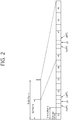
- FIG. 2 shows the structure of a TDD radio frame.
- a downlink (DL) subframe and an uplink (UL) subframe coexist in a TDD radio frame used in TDD.
- Table 1 shows an example of a UL-DL configuration of the radio frame.
- Uplink-downlink configuration Downlink-to-uplink switch-point periodicity Subframe n 0 1 2 3 4 5 6 7 8 9 0 5 ms D S U U U D S U U U 1 5 ms D S U U D D S U U U 2 5 ms D S U D D D S U D D D 3 10 ms D S U U U D D D D D D 4 10 ms D S U U D D D D D D 5 10 ms D S U D D D D D D D D 6 5 ms D S U U U U D S U U U D S U U D
- 'D' indicates a DL subframe
- 'U' indicates a UL subframe
- 'S' indicates a special subframe.
- a subframe having an index #1 and an index #6 may be a special subframe, and includes a downlink pilot time slot (DwPTS), a guard period (GP), and an uplink pilot time slot (UpPTS).
- the DwPTS is used in initial cell search, synchronization, or channel estimation in UE.
- the UpPTS is used for channel estimation in a BS and for the uplink transmission synchronization of UE.
- the GP is an interval in which interference occurring in UL due to the multi-path delay of a DL signal between UL and DL is removed.
- the TDD radio frame may be simply referred to as a TDD frame.
- FIG. 3 shows an example of a resource grid for one downlink slot.
- the downlink slot includes a plurality of Orthogonal Frequency Division Multiplexing (OFDM) symbol in the time domain and includes N RB Resource Blocks (RBs) in the frequency domain.
- the RBs includes one slot in the time domain and a plurality of consecutive subcarrier in the frequency domain in a resource allocation unit.
- the number of RBs N RB included in the downlink slot depends on a downlink transmission bandwidth N DL configured in a cell.
- the N RB can be any one of 6 to 110.
- An uplink slot can have the same structure as the downlink slot.
- Each element on the resource grid is called a Resource Element (RE).
- the RE on the resource grid can be identified by an index pair (k,1) within a slot.
- the number of OFDM symbols and the number of subcarriers within an RB are not limited thereto.
- the number of OFDM symbols and the number of subcarriers can be changed in various ways depending on the length of a CP, frequency spacing, etc.
- one OFDM symbol one of 128, 256, 512, 1024, 1536, and 2048 can be selected and used as the number of subcarriers.
- FIG. 4 shows the structure of a DL subframe.
- a downlink (DL) subframe is divided into a control region and a data region in the time domain.
- the control region includes a maximum of former 3 (maximun 4 according to circumstances) OFDM symbols of a first slot within a sub frame, but the number of OFDM symbols included in the control region can be changed.
- a control channel different from a physical downlink control channel (PDCCH) is allocated to the control region, and a physical downlink shared channel (PDSCH) is allocated to the data region.
- PDCCH physical downlink control channel
- PDSCH physical downlink shared channel
- physical channels can be divided into a physical downlink shared channel (PDSCH) and a physical uplink shared channel (PUSCH), that is, data channels, and a physical downlink control channel (PDCCH), a physical control format indicator channel (PCFICH), a physical hybrid-ARQ indicator channel (PHICH), and a physical uplink control channel (PUCCH), that is, control channels.
- PDSCH physical downlink shared channel
- PUSCH physical uplink shared channel
- PCFICH physical control format indicator channel
- PHICH physical hybrid-ARQ indicator channel
- PUCCH physical uplink control channel
- a PCFICH that is transmitted in the first OFDM symbol of a subframe carries a Control Format Indicator (CFI) regarding the number of OFDM symbols (i.e., the size of a control region) that are used to send control channels within the subframe.
- CFI Control Format Indicator
- UE first receives a CFI on a PCFICH and then monitors PDCCHs.
- a PCFICH is not subject to blind decoding, but is transmitted through the fixed PCFICH resources of a subframe.
- a PHICH carries a positive-acknowledgement (ACK)/negative-acknowledgement (NACK) signal for an uplink Hybrid Automatic Repeat reQuest (HARQ).
- ACK positive-acknowledgement
- NACK negative-acknowledgement
- HARQ Hybrid Automatic Repeat reQuest
- An ACK/NACK signal for uplink (UL) data on a PUSCH which is transmitted by UE is transmitted on a PHICH.
- a physical broadcast channel is transmitted in the former 4 OFDM symbols of a second slot within the first subframe of a radio frame.
- the PBCH carries system information that is essential for UE to communicate with a BS, and system information transmitted through a PBCH is called a Master Information Block (MIB).
- MIB Master Information Block
- SIB System Information Block
- SIB System Information Block
- DCI Downlink Control Information
- DCI can include the resource allocation of a PDSCH (this is also called a DL grant), the resource allocation of a PUSCH (this is also called an UL grant), a set of transmit power control commands for individual MSs within a specific UE group and/or the activation of a Voice over Internet Protocol (VoIP).
- DCI has different formats, which will be described later.
- a channel region in a subframe includes a plurality of control channel elements (CCEs).
- CCE is a logical allocation unit used to provide a coding rate according to the state of a radio channel to a PDCCH and corresponds to a plurality of resource element groups (REGs).
- An REG includes a plurality of REs.
- a PDCCH format and the number of available PDCCH bits are determined based on a relationship between the number of CCEs and a coding rate provided by CCEs.
- One REG includes four REs, and one CCE includes nine REGs.
- ⁇ 1, 2, 4, 8 ⁇ CCEs may be used, and each element of ⁇ 1, 2, 4, 8 ⁇ is defined as a CCE aggregation level.
- the number of CCEs used to transmit a PDDCH is determined by a base station based on a channel state.
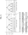
- FIG. 5 illustrates an example of PDCCH monitoring.
- blind decoding is used to detect a PDCCH.
- Blind decoding is a process of de-masking a cyclic redundancy check (CRC) of a received PDCCH (PDCCH candidate) with a desired identifier to check a CRC error, thereby allowing a UE to identify whether the PDCCH is a control channel of the UE.
- the UE does not recognize a position in which a PDCCH thereof is transmitted in a control region and a CCE aggregation level or DCI format used to transmit the PDCCH.
- a plurality of PDCCHs may be transmitted in one subframe.
- the UE monitors a plurality of PDCCHs in each subframe.
- monitoring refers to an attempt of the UE to decode a PDCCH according to a monitored PDCCH format.
- a search space is used to reduce load caused by blind decoding.
- a search space may denote a monitoring set of CCEs for a PDCCH.
- a UE monitors a PDCCH in a corresponding search space.
- a search space is divided into a common search space (CSS) and a UE-specific search space (USS).
- a CSS is a space for searching for a PDCCH having common control information, which includes 16 CCEs with CCE indexes of 0 to 15 and supports a PDCCH having a CCE aggregation level of ⁇ 4, 8 ⁇ .
- a PDCCH (DCI format 0 and 1A) carrying UE-specific information may also be transmitted to the CSS.
- the USS supports a PDCCH having a CEE aggregation level of ⁇ 1, 2, 4, 8 ⁇ .
- a different start point of a search space is defined for a CSS and a USS.
- a start point of a CSS is fixed regardless of subframes, while a start point of a USS may change by subframe according to an UE ID (for example, C-RNTI), a CCE aggregation level and/or a slot number in a radio frame.
- an UE ID for example, C-RNTI
- CCE aggregation level for example, C-RNTI
- slot number for example, a slot number
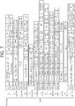
- FIG. 6 illustrates structures of DCI formats used in FDD
- FIG. 7 illustrates structures of DCI formats used in TDD.
- DCI format #A is represented simply by #A.
- the DCI formats include fields to be described below, and the respective fields may be mapped to information bits a 0 to a A-1 .
- the respective fields may be mapped in order described in each DCI format and include padding bits 0.
- a first field may be mapped to a lowest-order information bit a 0
- other consecutive fields may be mapped to high-order information bits.
- a most significant bit (MSB) in each field may be mapped to a lowest-order information bit in the field. For example, an MSB in the first field may be mapped to a 0 .
- a set of fields included in each conventional DCI format is referred to as an information field.
- DCI format 0 is used for PUSCH scheduling in one uplink cell.
- the following information (fields) is transmitted through DCI format 0: 1) Carrier indicator field (CIF, same hereinafter), which may have a length of 0 or 3 bits; 2) Flag for DCI format 0 and DCI format 1A differentiation (0 indicates DCI format 0 and 1 indicates DCI format 1A); 3) Frequency hopping flag (1 bit); 4) Resource block assignment and hopping resource allocation; 5) Modulation and coding scheme and redundancy version (5 bits); 6) New data indicator (1 bit); 7) TPC command for scheduled PUSCH (2 bits); 8) Cyclic shift for DM-RS and orthogonal cover code (OCC) index (3 bits); 9) UL index (2 bits); 10) Downlink assignment index (DAI, only for TDD); 11) CSI request; 12) Sounding reference signal (SRS) request (present only in DCI formats scheduling a PUSCH, mapped to a USS); and 13) Resource allocation type (present only when the number of
- DCI format 1 is used for scheduling one PDSCH codeword in one cell.
- the following information is transmitted through DCI format 1: 1) CIF (0 or 3 bits); 2) Resource allocation header (indicating resource allocation type 0/type 1) - not included on the assumption of resource allocation type 0 when a downlink bandwidth is smaller than 10 PRB, the resource allocation header is not included; 3) Resource block assignment; 4) Modulation and coding scheme (5 bits); 5) HARQ process number (3 bits for FDD and 4 bits for TDD); 6) New data indicator (1 bit); 7) Redundancy version (2 bits); 8) TPC command for PUCCH (2 bits); 9) DAI (2 bits, only for TDD); and 10) HARQ-ACK resource offset (2 bits).
- DCI format 1 If the number of information bits in DCI format 1 is equal to that in DCI format 0/1A, one bit having a value of 0 is added to DCI format 1. If the number of information bits in DCI format 1 is one of ⁇ 12, 14, 16, 20, 24, 26, 32, 40, 44, 56 ⁇ , one or more bits having a value of 0 are added to DCI format 1 so that DCI format 1 has a different payload size from ⁇ 12, 14, 16, 20, 24, 26, 32, 40, 44, 56 ⁇ and payload sizes of DCI format 0/1A.
- DCI format 1A is used for compact scheduling of one PDSCH in one cell codeword or a random access process induced by a PDCCH command.
- DCI corresponding to a PDCCH command may be transmitted through a PDCCH or enhanced PDCCH (EPDCCH).
- PDCCH enhanced PDCCH
- DCI format 1A The following information is transmitted through DCI format 1A: 1) CIF (0 or 3 bits); 2) Flag for DCI format 0 and DCI format 1A differentiation (1 bit); 3) Localized/distributed virtual resource block (VRB) assignment flag (1 bit); 4) Resource block assignment; 5) Preamble index (6 bits); 6) Physical random access channel (PRACH) mask index (4 bits); 7) Modulation and coding scheme (5 bits); 8) HARQ process number (3 bits); 9) New data indicator (1 bit); 10) Redundancy version (2 bits); 11) TPC command for PUCCH (2 bits); 12) DAI (2 bits, only for TDD); 13) SRS request (0 or 1 bit); and 14) HARQ-ACK resource offset (2 bits).
- DCI format 1A If the number of information bits in DCI format 1A is smaller than the number of information bits in DCI format 0, bits having a value of 0 are added so that DCI format 1A has the same payload size as DCI format 0. If the number of information bits in DCI format 1A is one of ⁇ 12, 14, 16, 20, 24, 26, 32, 40, 44, 56 ⁇ , one bit having a value of 0 is added to DCI format 1A.
- DCI format 1B includes precoding information and is used for simple scheduling of one PDSCH codeword in one cell.
- the following information is transmitted through DCI format 1B: 1) CIF (0 or 3 bits); 2) Localized/distributed (VRB) assignment flag (1 bit); 3) Resource block assignment; 4) Modulation and coding scheme (5 bits); 5) HARQ process number (3 bits); 6) New data indicator (1 bit); 7) Redundancy version (2 bits); 8) TPC command for PUCCH (2 bits); 9) DAI (2 bits, only for TDD); 10) Transmitted precoding matrix indicator (TPMI) information for precoding; and 11) PMI confirmation for precoding (1 bit). If the number of information bits in DCI format 1B is equal to one of ⁇ 12, 14, 16, 20, 24, 26, 32, 40, 44, 56 ⁇ , one bit having a value of 0 is added to DCI format 1B.
- DCI format 1C is used for very compact scheduling of one PDSCH codeword and multicast control channel (MCCH) change notification.
- MCCH multicast control channel
- the very compact scheduling the following information is transmitted through DCI format 1C: 1) Gap value indicator (1 bit); 2) Resource block assignment; and 3) Modulation and coding scheme.
- the MCCH change notification the following information is transmitted through DCI format 1C: 1) MCCH change notification information (8 bits); and 2) Reserved information bits.
- DCI format 1D includes precoding and power offset information and is used for simple scheduling of one PDSCH codeword in one cell.
- DCI format 1D The following information is transmitted through DCI format 1D: 1) CIF (0 or 3 bits); 2) Localized/distributed (VRB) assignment flag (1 bit); 3) Resource block assignment; 4) Modulation and coding scheme (5 bits); 5) HARQ process number (3 bits for FDD and 4 bits for TDD); 6) New data indicator (1 bit); 7) Redundancy version (2 bits); 8) TPC command for PUCCH (2 bits); 9) DAI (2 bits, only for TDD); 10) TPMI information for precoding; 11) Downlink power offset (1 bit); and 12) HARQ-ACK resource offset (2 bits). If the number of information bits in DCI format ID is equal to one of ⁇ 12, 14, 16, 20, 24, 26, 32, 40, 44, 56 ⁇ , one bit having a value of 0 is added to DCI format ID.
- DCI format 2 is used for assignment of a PDSCH for a closed-loop MIMO operation.
- the following information is transmitted through DCI format 2: 1) CIF (0 or 3 bits); 2) Resource allocation header (1bit); 3) Resource block assignment; 4) TPC command for PUCCH (2 bits); 5) DAI (2 bits, only for TDD); 6) HARQ process number (3 bits for FDD and 4 bits for TDD); 7) Transport block to codeword swap flag (1 bit); 8) Modulation and coding scheme (5 bits); 9) New data indicator (1 bit); 10) Redundancy version (2 bits); 11) Precoding information; and 12) HARQ-ACK resource offset. 8) to 10) may be given to each transport block.
- DCI format 2A is used for assignment of a PDSCH for an open-loop MIMO operation.
- the following information is transmitted through DCI format 2A: 1) CIF (0 or 3 bits); 2) Resource allocation header (1bit); 3) Resource block allocation; 4) TPC command for PUCCH (2 bits); 5) Downlink assignment flag (DAI, 2 bits, only for TDD); 6) HARQ process number (3 bits for FDD and 4 bits for TDD); 7) Transport block to codeword swap flag (1 bit); 8) Modulation and coding scheme (5 bits); 9) New data indicator (1 bit); 10) Redundancy version (2 bits); 11) Precoding information; and 12) HARQ-ACK resource offset.
- DCI format 2B The following information is transmitted through DCI format 2B: 1) CIF (0 or 3 bits); 2) Resource allocation header (1bit); 3) Resource block allocation; 4) TPC command for PUCCH (2 bits); 5) Downlink assignment flag (DAI, 2 bits, only for TDD); 6) HARQ process number (3 bits for FDD and 4 bits for TDD); 7) Scrambling identity (ID) (1 bit); 8) SRS request (0 or 1 bit); 9) Modulation and coding scheme (5 bits); 10) New data indicator (1 bit); 11) Redundancy version (2 bits); and 12) HARQ-ACK resource offset.
- DCI format 2B The following information is transmitted through DCI format 2B: 1) CIF (0 or 3 bits); 2) Resource allocation header (1bit); 3) Resource block allocation; 4) TPC command for PUCCH (2 bits); 5) Downlink assignment flag (DAI, 2 bits, only for TDD); 6) HARQ process number (3 bits for FDD and 4 bits for TDD); 7) Scrambling identity (ID) (1 bit); 8) SRS request
- DCI format 2C The following information is transmitted through DCI format 2C: 1) CIF (0 or 3 bits); 2) Resource allocation header (1bit); 3) Resource block allocation; 4) TPC command for PUCCH (2 bits); 5) Downlink assignment flag (DAI, 2 bits, only for TDD); 6) HARQ process number (3 bits for FDD and 4 bits for TDD); 7) Antenna port, scrambling ID and number of layers (3 bits); 8) SRS request (0 or 1 bit); 9) Modulation and coding scheme (5 bits); 10) New data indicator (1 bit); 11) Redundancy version (2 bits); and 12) HARQ-ACK resource offset.
- DCI format 2C 1 CIF (0 or 3 bits); 2) Resource allocation header (1bit); 3) Resource block allocation; 4) TPC command for PUCCH (2 bits); 5) Downlink assignment flag (DAI, 2 bits, only for TDD); 6) HARQ process number (3 bits for FDD and 4 bits for TDD); 7) Antenna port, scrambling ID and number of layers (3 bits); 8) S
- DCI format 2D The following information is transmitted through DCI format 2D: 1) CIF (0 or 3 bits); 2) Resource allocation header (1bit); 3) Resource block allocation; 4) TPC command for PUCCH (2 bits); 5) Downlink assignment flag (DAI, 2 bits, only for TDD); 6) HARQ process number (3 bits for FDD and 4 bits for TDD); 7) Antenna port, scrambling ID and number of layers (3 bits); 8) SRS request (0 or 1 bit); 9) Modulation and coding scheme (5 bits); 10) New data indicator (1 bit); 11) Redundancy version (2 bits); 12) PDSCH resource element mapping and quasi-co-location indicator; and 13) HARQ-ACK resource offset.
- DCI format 3 is used to transmit TPC commands for a PUCCH and PUSCH with 2-bit power adjustment.
- N TCP commands may be transmitted through DCI format 3.
- DCI format 3A is used to transmit TPC commands for a PUCCH and PUSCH with 1-bit power adjustment.
- M TCP commands may be transmitted through DCI format 3A.
- DCI format 4 is used for scheduling of a PUSCH in one uplink cell having a multi-antenna port transmission mode.
- FIG. 8 shows the structure of an UL subframe.
- the UL subframe can be divided into a control region to which a physical uplink control channel (PUCCH) for carrying uplink control information is allocated and a data region to which a physical uplink shared channel (PUSCH) for carrying user data is allocated in the frequency domain.
- PUCCH physical uplink control channel
- PUSCH physical uplink shared channel
- a PUCCH is allocated with an RB pair in a subframe. RBs that belong to an RB pair occupy different subcarriers in a fist slot and a second slot. An RB pair has the same RB index m.
- a PUCCH supports multiple formats.
- a PUCCH having a different number of bits in each subframe can be used according to a modulation scheme that is dependent on a PUCCH format.
- Table 2 shows an example of modulation schemes and the number of bits per subframe according to PUCCH formats.
- PUCCH format Modulation scheme Number of bits per subframe 1 N/A N/A 1a BPSK 1 1b QPSK 2 2 QPSK 20 2a QPSK+BPSK 21 2b QPSK+QPSK 22
- the PUCCH format 1 is used to send a Scheduling Request (SR), the PUCCH formats la/lb are used to send an ACK/NACK signal for an HARQ, the PUCCH format 2 is used to send a CQI, and the PUCCH formats 2a/2b are used to send a CQI and an ACK/NACK signal at the same time.
- SR Scheduling Request
- the PUCCH formats la/lb are used.
- the PUCCH format 1 is used.
- the PUCCH format 1 is used.
- the PUCCH format 1 is used. In this case, the ACK/NACK signal is modulated into resources allocated to the SR and is then transmitted.
- All the PUCCH formats use the Cyclic Shift (CS) of a sequence in each OFDM symbol.
- a CS sequence is generated by cyclically shifting a base sequence by a specific CS amount.
- the specific CS amount is indicated by a CS index.
- u is a root index
- n is an element index wherein 0 ⁇ n ⁇ N-1
- N is the length of the base sequence.
- b(n) is defined in section 5.5 of 3GPP TS 36.211 V8.7.0.
- the length of a sequence is the same as the number of elements included in the sequence.
- U can be determined by a cell identifier (ID), a slot number within a radio frame, etc.
- the length N of the base sequence becomes 12 because one resource block includes 12 subcarriers.
- a different base sequence is defined depending on a different root index.
- a CS sequence r(n, I cs ) can be generated by cyclically shifting the base sequence r(n) as in Equation 2.
- r n I cs r n ⁇ exp j 2 ⁇ ⁇ I cs n N , 0 ⁇ I cs ⁇ N ⁇ 1
- I cs is a CS index indicative of a CS amount (0 ⁇ I cs ⁇ N-1).
- An available CS index of a base sequence refers to a CS index that can be derived from the base sequence according to a CS interval.
- the length of a base sequence is 12 and a CS interval is 1, a total number of available CS indices of the base sequence becomes 12.
- a total number of available CS indices of the base sequence becomes 6.
- FIG. 9 shows the channel structure of the PUCCH format 1b in a normal CP.
- One slot includes 7 OFDM symbols, the 3 OFDM symbols become Reference Signal (RS) OFDM symbols for a reference signal, and the 4 OFDM symbols become data OFDM symbols for an ACK/NACK signal.
- RS Reference Signal
- a modulation symbol d(0) is generated by performing Quadrature Phase Shift Keying (QPSK) modulation on an encoded 2-bit ACK/NACK signal.
- QPSK Quadrature Phase Shift Keying
- a CS index I cs can vary depending on a slot number 'ns' within a radio frame and/or a symbol index '1' within a slot.
- the modulation symbol d(0) is spread into a CS sequence r(n,Ics). Assuming that a 1-dimensional spread sequence corresponding to an (i+1) th OFDM symbol is m(i) in a slot,
- the 1-dimensional spread sequence can be spread using an orthogonal sequence.
- K a spreading factor
- a different spreading factor can be used in each slot.
- the 2-dimensional spread sequences ⁇ s(0), s(1), s(2), s(3) ⁇ are subject to IFFT and then transmitted in a corresponding OFDM symbol. Accordingly, an ACK/NACK signal is transmitted on a PUCCH.
- An orthogonal sequence index i, a CS index I cs , and an RB index m are parameters necessary to configure a PUCCH and are also resources used to classify PUCCHs (or MSs). If the number of available CSs is 12 and the number of available orthogonal sequence indices is 3, a PUCCH for a total of 36 MSs can be multiplexed with one RB.
- a resource index n (1) PUCCH is defined so that UE can obtain the three parameters for configuring a PUCCH.
- the resource index n (1) PUCCH n CCE + N (1) PUCCH , wherein n CCE is the number of the first CCE used to send a corresponding PDCCH (i.e., PDCCH including the allocation of DL resources used to received downlink data corresponding to an ACK/NACK signal), and N (1) PUCCH is a parameter that is informed of UE by a BS through a higher layer message.
- Time, frequency, and code resources used to send an ACK/NACK signal are called ACK/NACK resources or PUCCH resources.
- an index of ACK/NACK resources (called an ACK/NACK resource index or PUCCH index) used to send an ACK/NACK signal on a PUCCH can be represented as at least one of an orthogonal sequence index i, a CS index I cs , an RB index m, and an index for calculating the 3 indices.
- ACK/NACK resources can include at least one of an orthogonal sequence, a CS, a resource block, and a combination of them.
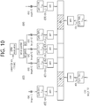
- FIG.10 shows the channel structure of the PUCCH formats 2/2a/2b in a normal CP.
- OFDM symbols 1 and 5 are used to send a demodulation reference signal (DM RS),t hat is, an uplink reference signal, and the remaining OFDM symbols are used to send a CQI.
- DM RS demodulation reference signal
- an OFDM symbol 3 fourth symbol is used for a DM RS.
- 10 CQI information bits can be subject to channel coding at a 1/2 code rate, for example, thus becoming 20 coded bits.
- Reed-Muller code can be used in the channel coding.
- the 20 coded bits are scramble and then subject to QPSK constellation mapping, thereby generating a QPSK modulation symbol (d(0) to d(4) in a slot 0).
- Each QPSK modulation symbol is modulated in a cyclic shift of a base RS sequence 'r(n)' having a length of 12, subject to IFFT, and then transmitted in each of 10 SC-FDMA symbols within a subframe.
- Uniformly spaced 12 CSs enable 12 different MSs to be orthogonally multiplexed in the same PUCCH RB.
- Abase RS sequence 'r(n)' having a length of 12 can be used as a DM RS sequence applied to OFDM symbols 1 and 5.
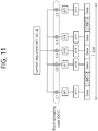
- FIG. 11 shows an example of a channel structure of a PUCCH format 3.
- the PUCCH format 3 is a PUCCH format which uses a block spreading scheme.
- the block spreading scheme means a method of spreading a symbol sequence, which is obtained by modulating a multi-bit ACK/NACK, in a time domain by using a block spreading code.
- a symbol sequence (e.g., ACK/NACK symbol sequence) is transmitted by being spread in the time domain by using the block spreading code.
- An orthogonal cover code (OCC) may be used as the block spreading code.
- Control signals of several UEs may be multiplexed by the block spreading code.
- a symbol e.g., d(0), d(1), d(2), d(3), d(4), etc., of FIG. 7
- UE multiplexing is performed using the cyclic shift of a constant amplitude zero auto-correlation (CAZAC) sequence.
- CAZAC constant amplitude zero auto-correlation
- a symbol sequence including one or more symbols is transmitted in a frequency domain of each data symbol, the symbol sequence is spread in a time domain by using the block spreading code, and UE multiplexing is performed.
- An example in which 2 RS symbols are used in one slot has been illustrated in FIG. 11 , but the present invention is not limited thereto. 3 RS symbols may be used, and an OCC having a spreading factor value of 4 may be used.
- An RS symbol may be generated from a CAZAC sequence having a specific cyclic shift and may be transmitted in such a manner that a plurality of RS symbols in the time domain has been multiplied by a specific OCC.
- the carrier aggregation system is also called a multiple carrier system.
- a 3GPP LTE system supports a case where a DL bandwidth and a UL bandwidth are differently configured, but one component carrier (CC) is a precondition in this case.
- a 3GPP LTE system supports a maximum of 20 MHz and may be different in a UL bandwidth and a DL bandwidth, but supports only one CC in each of UL and DL
- a carrier aggregation also called a bandwidth aggregation or a spectrum aggregation
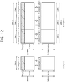
- FIG. 12 shows an example of a comparison between a single carrier system and a carrier aggregation system.
- a carrier aggregation system ( FIG. 12 (b) ) has been illustrated as including three DL CCs and three UL CCs, but the number of DL CCs and UL CCs is not limited.
- a PDCCH and a PDSCH may be independently transmitted in each DL CC, and a PUCCH and a PUSCH may be independently transmitted in each UL CC. Or, a PUCCH may be transmitted only through a specific UL CC.
- a UE Since three pairs of DL CCs and UL CCs are defined, it can be said that a UE is served from three serving cells.
- a serving cell a cell which is configured to provide a service to a user equipment is referred to a serving cell.
- the UE may monitor PDCCHs in a plurality of DL CCs and receive DL transport blocks through the plurality of DL CCs at the same time.
- the UE may send a plurality of UL transport blocks through a plurality of UL CCs at the same time.
- a pair of a DL CC #A and a UL CC #A may become a first serving cell
- a pair of a DL CC #B and a UL CC #B may become a second serving cell
- a DL CC #C and a UL CC#C may become a third serving cell.
- Each serving cell may be identified by a cell index (CI).
- the CI may be unique within a cell or may be UE-specific.
- the serving cell may be divided into a primary cell and a secondary cell.
- the primary cell is a cell on which the UE performs an initial connection establishment procedure or initiates a connection re-establishment procedure, or a cell designated as a primary cell in a handover process.
- the primary cell is also called a reference cell.
- the secondary cell may be configured after an RRC connection has been established and may be used to provide additional radio resources. At least one primary cell is always configured, and a secondary cell may be added/modified/released in response to higher layer signaling (e.g., an RRC message).
- the CI of the primary cell may be fixed. For example, the lowest CI may be designated as the CI of the primary cell.
- the primary cell includes a downlink primary component carrier (DL PCC) and an uplink PCC (UL PCC) in view of a CC.
- the secondary cell includes only a downlink secondary component carrier (DL SCC) or a pair of a DL SCC and a UL SCC in view of a CC.
- DL SCC downlink secondary component carrier
- 'cell' may be mixed with the term 'component carrier (CC)'.
- the carrier aggregation system may support a plurality of CCs, that is, a plurality of serving cells unlike the single carrier system.
- Such a carrier aggregation system may support cross-carrier scheduling.
- the cross-carrier scheduling is a scheduling method capable of performing resource allocation of a PDSCH transmitted through a different component carrier through a PDCCH transmitted through a specific component carrier and/or resource allocation of a PUSCH transmitted through other component carriers except for a component carrier fundamentally linked with the specific component carrier. That is, the PDCCH and the PDSCH may be transmitted through different DL CCs, and a PUSCH may be transmitted through a UL CC different from a UL CC linked with a DL CC to which a PDCCH including a UL is transmitted.
- the PDCCH needs a carrier indicator indicating that PDSCH/PUSCH are transmitted through a certain DL CC/UL CC.
- a field including the carrier indicator refers to a carrier indication field (CIF).
- the carrier aggregation system that supports the cross-carrier scheduling may include a carrier indication field (CIF) to the conventional downlink control information (DCI).
- CIF carrier indication field
- DCI downlink control information
- 3 bits may be extended since the CIF is added to the conventional DCI format (i.e., the DCI format used in LTE), and the PDCCH structure may reuse the conventional coding method, resource allocation method (i.e., resource mapping based on the CCE), and the like.
- a BS may set a PDCCH monitoring DL CC (monitoring CC) group.
- the PDCCH monitoring DL CC group is configured by a part of all aggregated DL CCs. If the cross-carrier scheduling is configured, the UE performs PDCCH monitoring/decoding for only a DL CC included in the PDCCH monitoring DL CC group. That is, the BS transmits a PDCCH with respect to a PDSCH/PUSCH to be scheduled through only the DL CCs included in the PDCCH monitoring DL CC group.
- the PDCCH monitoring DL CC group may be configured in a UE-specific, UE group-specific, or cell-specific manner.
- Non-cross carrier scheduling is a scheduling method capable of performing resource allocation of a PDSCH transmitted through a specific component carrier through a PDCCH transmitted through the specific component carrier and/or resource allocation of a PDSCH transmitted through a component carrier fundamentally linked with the specific component carrier.
- a DL subframe and an UL subframe coexist in one radio frame.
- the number of UL subframes is smaller than that of DL subframes. Accordingly, in preparation for a case where UL subframes for sending an ACK/NACK signal are not sufficient, a plurality of ACK/NACK signals for DL transport blocks received in a plurality of DL subframes is transmitted in one UL subframe.
- UE In ACK/NACK bundling, UE sends ACK if it has successfully decoded all received PDSCHs (i.e., DL transport blocks) and sends NACK in other cases. To this end, ACK or NACKs for each PDSCH are compressed through logical AND operations.
- ACK/NACK multiplexing is also called ACK/NACK channel selection (or simply channel selection).
- UE selects one of a plurality of PUCCH resources and sends ACK/NACK.
- Table below shows DL subframes n-k associated with an UL subframe n according to an UL-DL configuration in 3GPP LTE, wherein k ⁇ K and M is the number of elements of a set K.
- UL-DL Configuration Subframe n 0 1 2 3 4 5 6 7 8 9 0 - - 6 - 4 - - 6 - 4 1 - - 7, 6 4 - - - 7, 6 4 - 2 - - 8, 7, 4, 6 - - - - 8, 7, 4, 6 - - 3 - - 7, 6, 11 6, 5 5, 4 - - - - - 4 - 12, 8, 7, 11 6, 5, 4, 7 - - - - - - - 5 - - 13, 12, 9, 8, 7, 5, 4, 11, 6 - - - - - - - 6 - - 7 7 5 - - 7 7 - - 7 - - 7 - - 7 - - 7 - - 7
- UE can obtain 3 PUCCH resources n (1) PUCCH,0 , n (1) PUCCH,1 , and n (1) PUCCH,2 because it can receive 3 PDCCHs from 3 DL subframes.
- an example of ACK/NACK channel selection is the same as the following table.
- HARQ-ACK(0),HARQ-ACK(1),HARQ-ACK(2) n PUCCH b(0),b(1) ACK, ACK, ACK n (1) PUCCH,2 1,1 ACK, ACK, NACK/DTX n (1) PUCCH,1 1,1 ACK, NACK/DTX, ACK n (1) PUCCH,0 1,1 ACK, NACK/DTX, NACK/DTX n (1) PUCCH,0 0,1 NACK/DTX, ACK, ACK n (1) PUCCH,2 1,0 NACK/DTX, ACK, NACK/DTX n (1) PUCCH,1 0,0 NACK/DTX, NACK/DTX, ACK n (1) PUCCH,2 0,0 DTX, DTX, NACK n (1) PUCCH,2 0,1 DTX, NACK, NACK/DTX n (1) PUCCH,2 0,1 DTX, NACK, NACK/DTX n (1) PUCCH,1 1,0 NACK, NACK/DTX
- HARQ-ACK(i) indicates ACK/NACK for an i th DL subframe of M DL subframes.
- Discontinuous transmission means that a DL transport block has not been received on a PDSCH in a corresponding DL subframe or that a corresponding PDCCH has not been detected.
- 3 PUCCH resources n (1) PUCCH,0 , n (1) PUCCH,1 , and n (1) PUCCH,2 are present, and b(0), b(1) are two bits transmitted using a selected PUCCH.
- ACK/NACK channel selection if at least one ACK is present, NACK and DTX are coupled. This is because all ACK/NACK states cannot be represented by a combination of reserved PUCCH resources and a QPSK symbol. If ACK is not present, however, DTX is decoupled from NACK.
- the above-described ACK/NACK bundling and ACK/NACK multiplexing can be applied in the case where one serving cell has been configured in UE in TDD.
- UE sends ACK/NACK in a subframe n if the UE detects a PDSCH indicated by a corresponding PDCCH in a subframe n-k of a primary cell or detects a Semi-Persistent Scheduling (SPS) release PDCCH.
- SPS Semi-Persistent Scheduling
- a BS can inform UE that semi-persistent transmission and reception are performed in what subframes through a higher layer signal, such as Radio Resource Control (RRC). Parameters given by the higher layer signal can be, for example, the periodicity of a subframe and an offset value.
- RRC Radio Resource Control
- the UE When the UE receives the activation or release signal of SPS transmission through a PDCCH after recognizing semi-persistent transmission through the RRC signaling, the UE performs or releases SPS PDSCH reception or SPS PUSCH transmission. That is, the UE does not immediately perform SPS transmission/reception although SPS scheduling is allocated thereto through the RRC signaling, but when an activation or release signal is received through a PDCCH, performs SPS transmission/reception in a subframe that corresponds to frequency resources (resource block) according to the allocation of the resource block designated by the PDCCH, modulation according to MCS information, a subframe periodicity allocated through the RRC signaling according to a code rate, and an offset value.
- a PDCCH that releases SPS is called an SPS release PDCCH
- a DL SPS release PDCCH that releases DL SPS transmission requires the transmission of an ACK/NACK signal.
- UE sends ACK/NACK using the PUCCH formats la/lb according to a PUCCH resource n (1,p) PUCCH .
- n (1,p) PUCCH indicates an antenna port p.
- the k is determined by Table 5.
- n (1,p) PUCCH can be allocated as in the following equation.
- P can be p0 or p1.
- Equation 3 c is selected in such a way as to satisfy N c ⁇ n CCE ⁇ N c+1 (antenna port p0), N c ⁇ (n CCE + 1) ⁇ N c+1 (antenna port p1) from among ⁇ 0,1,2,3 ⁇ .
- N (1) PUCCH is a value set by a higher layer signal.
- N C max ⁇ 0, floor [N DL RB ⁇ (N RB sc ⁇ c - 4)/36] ⁇ .
- the N DL RB is a DL bandwidth
- N RB SC is the size of an RB indicated by the number of subcarriers in the frequency domain.
- n CCE is a first CCE number used to send a corresponding PDCCH in a subframe n-k m .
- m is a value that makes k m the smallest value in the set K of Table 5.
- the UE can send ACK/NACK in the subframe n using the PUCCH resource n (1,p) PUCCH as follows.
- an SPS PDSCH does not include a scheduling PDCCH
- UE sends ACK/NACK through the PUCCH formats 1a/1b according to n (1,p) PUCCH that is configured by a higher layer signal.
- 4 resources a first PUCCH resource, a second PUCCH resource, a third PUCCH resource, and a fourth PUCCH resource
- one resource can be indicated through the Transmission Power Control (TPC) field of a PDCCH that activates SPS scheduling.
- TPC Transmission Power Control
- TPC field value Resource for channel selection '00' First PUCCH resource '01' Second PUCCH resource '10' Third PUCCH resource '11' Fourth PUCCH resource
- one serving cell is configured (i.e., only a primary cell is configured) in UE, ACK/NACK multiplexing is used, and M>1. That is, it is assumed that a plurality of DL subframes is associated with one UL subframe.
- a PUCCH resource n (1) PUCCH,i for sending ACK/NACK when UE receives a PDSCH in a subframe n-k i (0 ⁇ i ⁇ M-1) or detects a DL SPS release PDCCH can be allocated as in the following equation.
- k i ⁇ K, and the set K has been described with reference to Table 5.
- n 1 PUCCH , i M ⁇ i ⁇ 1 ⁇ N c + i ⁇ N c + 1 + n CCE , i + N 1 PUCCH
- N C max ⁇ 0, floor [N DL RB ⁇ (N RB sc ⁇ c - 4)/36] ⁇ .
- the N DL RB is a DL bandwidth
- N RB sc is the size of an RB indicated by the number of subcarriers in the frequency domain.
- n CCE,i is a first CCE number used to send a corresponding PDCCH in the subframe n - k i .
- PUCCH,i is determined by a configuration given by a higher layer signal and Table 7.
- the UE sends ACK/NACK using channel selection that uses the PUCCH format 1b or the PUCCH format 3.
- Channel selection that uses the PUCCH format 1b used in TDD can be performed as follows.
- UE performs spatial ACK/NACK bundling on a plurality of codewords within one DL subframe and sends spatially bundled ACK/NACK bits for each serving cell through channel selection that uses the PUCCH format 1b.
- Spatial ACK/NACK bundling means the compression of ACK/NACK for each codeword through logical AND operations within the same DL subframe.
- ACK/NACK bits are 4 bits or lower, spatial ACK/NACK bundling is not used and the ACK/NACK bits are transmitted through channel selection that uses the PUCCH format 1b.
- ACK/NACK bits are greater than 20 bits
- spatial ACK/NACK bundling can be performed in each serving cell and ACK/NACK bits subjected to spatial ACK/NACK bundling can be transmitted through the PUCCH format 3. If ACK/NACK bits are 20 bits or lower, spatial ACK/NACK bundling is not used and the ACK/NACK bits are transmitted through the PUCCH format 3.
- ACK/NACK can be transmitted through channel selection that uses the PUCCH format 1b.
- the UE can feed ACK/NACK for a maximum of 2 transport blocks, received in one serving cell, back to a BS by sending 2-bit (b(0)b(1)) information in one PUCCH resource selected from a plurality of PUCCH resources.
- One codeword can be transmitted in one transport block.
- a PUCCH resource can be indicated by a resource index n (1) PUCCH,i .
- A is any one of ⁇ 2, 3, 4 ⁇ , and i is 0 ⁇ i ⁇ (A-1).
- the 2-bit information is indicated as b(0)b(1).
- HARQ-ACK(j) indicates an HARQ ACK/NACK response that is related to a transport block or DL SPS release PDCCH transmitted by a serving cell.
- the HARQ-ACK(j), the serving cell, and the transport block can have the following mapping relationship.
- [Table 8] A HARQ-ACK(j) HARQ-ACK(0) HARQ-ACK(1) HARQ-ACK(2) HARQ-ACK(3) 2 Transport block 1 of primary cell Transport block 2 of secondary cell NA NA 3 Transport block 1 of serving cell 1 Transport block 2 of serving cell 1 Transport block 3 of serving cell 2 NA 4 Transport block 1 of primary cell Transport block 2 of primary cell Transport block 3 of secondary cell Transport block 4 of secondary cell
- HARQ-ACK(0) and HARQ-ACK(1) indicate ACK/NACKs for 2 transport blocks transmitted in a primary cell
- HARQ-ACK(2) and HARQ-ACK(3) indicate ACK/NACKs for 2 transport blocks transmitted in a secondary cell.
- n (1) PUCCH,i is determined to be n CCE,i +N (1) PUCCH .
- n CCE,i means an index of the first CCE that is used to send a PDCCH by a BS, and N (1) PUCCH is a value set through a higher layer signal. If a transmission mode of a primary cell supports up to two transport blocks, a PUCCH resource n (1) PUCCH,i+1 is given.
- n (1) PUCCH,i+1 can be determined to be n CCE,i + 1 + N (1) PUCCH . That is, if a primary cell is set in a transmission mode in which a maximum of up to 2 transport blocks can be transmitted, 2 PUCCH resources can be determined.
- PUCCH resources n (1) PUCCH,i and n (1) PUCCH,i+1 for a transmission mode in which up to 2 transport blocks are supported can be determined by a higher layer configuration.
- a downlink subframe and an uplink subfraem are present at different frequencies in each subframe.
- a downlink subframe may be present in a first frequency band (f1)
- an uplink subframe may be present in a second frequency band (f2).
- downlink subframes are consecutive, and uplink subframes are likewise consecutive.
- a ratio of downlink resources to uplink resources is fixed to 1:1. Accordingly, when a downlink/uplink traffic demand is changed or traffic demand is concentrated in either of the downlink and the uplink, the resources may not be efficiently used.
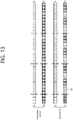
- FIG. 13 illustrates a first embodiment of switching part of uplink resources to downlink resources for use.
- a legacy FDD UE may use f1 for a downlink and f2 for an uplink.
- an advanced UE uses f1 for a downlink as in the legacy FDD UE.
- the advanced UE not only uses f2, which is used by the legacy FDD UE only for the uplink, for an uplink but may use part of resources (for example, subframes 131 represented by D) in f2 even for a downlink.
- the advanced UE may use f2, which is used by the legacy FDD UE only for the uplink, in a divided manner for the uplink and the downlink as necessary. For example, when traffic is concentrated in the downlink and there is little traffic in the uplink, a base station may allocate downlink subframes even for f2 to transmit downlink data. In this case, the base station may notify the UE of a configuration according to the first embodiment.
- the advanced UE supports the configuration and thus is capable of operating according to the first embodiment.
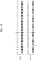
- FIG. 14 illustrates a second embodiment of switching part of uplink resources to downlink resources for use.
- a legacy FDD UE may use f1 for a downlink and f2 for an uplink.
- An advanced UE may not use f1.
- the advanced UE not only uses f2 for an uplink but may use part of resources (for example, subframes 141 represented by D) in f2 even for a downlink.
- a base station may notify the UE of a configuration according to the second embodiment.
- the base station may transmit the downlink subframe configuration information to the advanced UE, specifically through a downlink subframe 141 in f2.
- the base station may transmit the downlink subframe configuration information to the advanced UE through a downlink subframe in f1.
- This process may be possible on the assumption that the advanced UE supports carrier aggregation.
- a UE supporting no carrier aggregation may be allowed to use f1 or use a certain range of f2 switched for TDD in order to receive the downlink subframe configuration information.
- the downlink subframe configuration information may be signaled through an RRC message transmitted through a downlink subframe in f1.
- the downlink subframe configuration information may be signaled through a search space shared between a plurality of UEs, such as a common search space (CSS).
- the downlink subframe configuration information may indicate whether each subframe is switched a downlink subframe.
- the downlink subframe configuration information may indicate which pattern is used among configurable patterns determined for a plurality of subframes. For example, a plurality of patterns in which 10 subframes in a frame are allocated as downlink and uplink subframes is determined in advance, and the downlink subframe configuration information may indicate which pattern is used.
- the advanced UE using f2 used by the legacy UE only for the uplink, for the downlink and the uplink reuses an operation based on an existing TDD UL-DL configuration, thereby reducing complexity in implementation.
- UL/DL direction determination follows the existing TDD UL-DL configuration.
- PUCCH Physical Random access channel
- PRACH physical random access channel
- the base station may schedule an uplink channel of the legacy UE not to collide with downlink transmission for the advanced UE. To this end, the base station configures a default uplink frame for uplink channel transmission of the legacy UE for the advanced UE. Particularly, a PRACH transmission target uplink subframe of the legacy UE may be included in the default uplink subframe for the advanced UE.
- the default uplink subframe may be selected among subframes configured as uplink subframes in a UL/DL configuration assigned for the advanced UE.
- the advanced UE may be provided with a UL/DL configuration including the default uplink subframe in advance.
- subframes in f2 may be configured variably as downlink subframes or uplink subframes. Exceptionally, a subframe designated as the default uplink subframe may not be configured as a downlink subframe.
- a collision between a downlink subframe in the UL/DL configuration and the default uplink subframe may occur due to a signaling error or the like.
- the following methods may be considered.
- the UE may recognize the collision as an error and operate accordingly.
- the UE may recognize the downlink subframe in the UL/DL configuration as an uplink subframe and operate accordingly.
- the base station may perform downlink channel transmission for the advanced UE only in a region other than a default uplink region for uplink channel transmission for the legacy UE in f2.
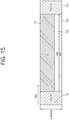
- FIG. 15 illustrates a configuration of a subframe allocable to the advanced UE.
- the configuration illustrated in FIG. 15 may be a subframe configuration according to the second method.
- the legacy UE transmits a PUCCH and an SRS in default uplink regions 151, 152 and 153 in uplink subframes.
- Downlink transmission for the advanced UE may be performed only in a portion 154 of a region excluding the default uplink regions.
- PUCCH regions 151 and 152 for transmitting the PUCCH may be excluded from downlink transmission for the advanced UE by PDSCH scheduling.
- an SRS region 153 for transmitting the SRS is excluded from allocation of downlink OFDM symbols and performs PDSCH data mapping via puncturing or rate-matching.
- Excluding the SRS region may be performed only in an SRS transmission subframe in a cell-specific SRS configuration of a legacy uplink. In downlink scheduling, the existence of the SRS transmission region may be signaled directly.
- a PRACH transmission band in a PRACH transmission target uplink subframe may be also configured as a default uplink region in a PRACH configuration of the legacy UE.
- a subframe or region for transmitting the specific signal may be configured as a default downlink subframe/region for the advanced UE.
- the advanced UE needs to perform downlink time/frequency synchronization with the base station. That is, the advanced UE needs to receive a primary synchronization signal (PSS), a secondary synchronization signal (SSS) or a cell-specific reference signal (CRS) for synchronization.
- PSS primary synchronization signal
- SSS secondary synchronization signal
- CRS cell-specific reference signal
- the subframe/region for transmitting the specific signal may be configured as the default downlink subframe/region.
- the advanced UE operating according to the first embodiment may configure only a subframe for transmitting a periodic RS for tracking or a CRS or CSI-RRS for CSI estimation as the default downlink subframe.
- a tracking/synchronization signal in f1 may be used as it is for downlink subframes in f2.
- the advanced UE operating according to the second embodiment may configure a default downlink subframe for a physical broadcast channel for system information transmission.
- the default downlink subframe may be selected among downlink subframes in a UL/DL configuration assigned to the advanced UE, or a UL/DL configuration including the default downlink subframe may be transmitted to the advanced UE.
- the default downlink subframe may be a subframe predetermined between the base station and the UE. Otherwise, the default downlink subframe may be configured by transmitting an RRC message in f1 or transmitting DCI through a CSS.
- a synchronization HARQ scheme is applied to PUSCH transmission in conventional FDD.
- the synchronization HARQ scheme is performed in order of UL grant reception, PUSCH transmission, PHICH reception, and PUSCH retransmission, in which UL grant reception and PHICH reception have a cycle of 8 ms and PUSCH transmission and PUSCH retransmission have a cycle of 8 ms.
- the reception processes are performed in f1 and the transmission processes are performed in f2.
- the UE may be signaled not to use part of UL/DL subframes defined in the TDD UL/DL configuration.
- the part of uplink/downlink subframes include a plurality of PRBs in the frequency domain, in which the UE may be signaled not to use all of the PRBs or only part of the PRBs for the downlink or uplink.
- the UE may assume that PRBs other than the unavailable PRBs are available for the downlink.
- a remaining region other than the PUCCH regions for the legacy UE may be configured for the downlink.
- scheduling of a downlink subframe in f2 may be performed through a downlink subframe in f1. This is similar to carrier aggregation.
- a separate carrier index (CI) is allocated to f2 and a data channel schedule of each carrier is separately coded and forwarded via separate DCI as in cross carrier scheduling.
- Scheduling for downlink subframes in f1 and scheduling for downlink subrames in f2 are distinguished using a CIF value of DCI.
- a CIF may be configured with 1 bit only.
- bundled scheduling may be used. For example, as in uplink scheduling in TDD UL-DL configuration 0, bitmaps for a downlink subframe in f1 and a downlink subframe in f2 are allocated to one DCI to indicate whether both the downlink subframe in f1 and the downlink subframe in f2 are scheduled or either thereof is scheduled.
- Such a bit field may be added only for a subframe possible for downlink scheduling in f2.
- Such downlink scheduling may be applied only to a specific TM-dependent DCI format.
- the advanced UE When the advanced UE operates according to the first embodiment, the advanced UE, which is configured with cross-carrier scheduling, assumes that a PDSCH starts on OFDM symbol #0. Even when a PDSCH start symbol is not configured as a value of 0 or even before configuration, the advanced UE assumes that a PDSCH starts on OFDM symbol #0.
- the advanced UE may assume that no CRS is transmitted in the downlink.
- the UE may assume that no CRS is transmitted.
- the UE may assume that no CRS is transmitted.
- the UE may assume that no CSS is transmitted in a downlink subframe in f2 DL.
- downlink scheduling since DCI is transmitted in the same subframe where a data channel is transmitted, self-carrier scheduling is possible.
- UL scheduling since DCI needs to be transmitted in an appointed downlink subframe before a uplink data channel transmission timing, configuration of a downlink subframe is restricted.
- uplink scheduling using a downlink subframe in f1 may be allowed for the advanced UE, whereas uplink scheduling using a downlink subframe in f2 may not be allowed.
- uplink scheduling for the advanced UE is performed in downlink subframes in f1 and uplink subframes in f2 UL by FDD.
- a downlink data channel in f1 may also be configured such that the downlink in f2 is configured to transmit only a PDSCH without transmitting a control channel, such as EPDCCH.
- a PUSCH transmission timing of the advanced UE may follow FDD.
- an HARQ-ACK may also be transmitted according to FDD as in aggregation of two FDD carriers.
- an uplink HARQ-ACK, CSI, and PHICH timing may be determined according to a UL/DL configuration of an actual TDD carrier in f2.
- the UEs Since UEs are at different distances from a base station, when the base station simultaneously transmits downlink signals for the respective UEs, the UEs may have different downlink signal reception timings due to a propagation delay or the like. Further, when the UEs transmit uplink signals based on the downlink signal reception timings, uplink signal transmission timings and timings (arrival timings) of the uplink signals reaching the base station may vary by the UEs.
- TA timing advance
- FIG. 16 illustrates an example of assigning a TA value.
- a UE starts transmission of an uplink radio frame i (N TA + N TA offset ) x T S seconds before a start timing of a corresponding downlink radio frame i.
- N TA offset may be 0 for FDD
- N TA offset may be 624 for TDD.
- N TA is a value signaled as an absolute value or relative value (increment) from a base station to the UE
- N TA offset is a value preset between the base station and the UE according to a duplexing mode (that is, FDD or TDD) of a corresponding frequency.
- a downlink subframe and an uplink subframe may overlap due to TA assignment.
- a gap as a guard interval may be applied to a portion which changes from the downlink to the uplink.
- a subframe in frequency band f2, used by an existing UE as an uplink subframe, may be used by an advanced UE as a dedicated downlink subframe.
- a gap may be applied to a last portion of the dedicated downlink subframe or a first portion of an uplink subframe following the dedicated downlink subframe. It is preferable that the gap is applied to the last portion of the dedicated downlink subframe considering that the uplink subframe is used by the existing UE.
- use of a part of OFDM symbols in the downlink subframe used by the advanced UE in frequency band f2 may be limited in order to apply the gap.
- consecutive downlink subframes are configured for the advanced UE in frequency band f2
- the gap may be applied to all of the downlink subframes.
- the gap may not be applied to a downlink subframe preceding a downlink subframe of the advanced UE completely excluding use of an uplink subframe of the existing UE.
- a TA reference may be a downlink subframe in frequency band f1 or a downlink subframe in frequency band f2.
- Using the downlink subframe in frequency band f1 as the reference is useful particularly when PUSCHs are scheduled by FDD, since frequency band f1 enables estimation of secure downlink synchronization.
- the latter case is useful when a channel in frequency band f2 is significantly different in characteristics from a channel in frequency band f1 and is useful for a UE receiving only a downlink in frequency band f2.
- N TA offset 0 may be applied instead of N TA offset of 624, which is for matching a TA with a UE operating in FDD and may be applied for PRACH transmission.
- FIG. 17 illustrates an example of a TA for an existing UE in FDD and a TA for an advanced UE.
- an uplink transmission timing in frequency band f2 precedes a downlink reception timing in frequency band f1 by TA.
- both uplink transmission and downlink reception are possible in frequency band f2.
- a gap represented by G may be included in the downlink subframe ( FIG. 17 (a) and (c) ) or in the uplink subframe ( FIG. 17 (b) and (d) ).
- downlink transmission from a base station to the advanced UE may be performed by an offset value in advance as compared with the existing UE.
- a TA is applied for uplink synchronization of a UE.
- the same idea may be applied for uplink synchronization of a UE using aggregation of an FDD cell and a TDD cell. That is, a UE using aggregation of an FDD cell and a TDD cell uses a TA offset (N TA offset ) of the FDD cell as a TA offset (N TA offset ) of the TDD cell or uses the TA offset (N TA offset ) of the TDD cell as the TA offset (N TA offset ) of the FDD cell.
- the UE may determine TA values for the first and second cells using a combination of a value (N TA,primarycell ) based on a value signaled from the primary cell and an offset value (N TA offset,primarycell ) predetermined according to a duplexing mode of the primary cell.
- TAG timing advance group
- N TA offset is defined differently for an FDD cell and a TDD cell, there is a need for a method of achieving uplink synchronization at the UE with downlink synchronization between the two cells being achieved.
- One method is to divide the FDD cell and the TDD cell to belong to different TAGs all the time.
- N TA is independently allocated the FDD cell and the TDD cell to configure a TA.
- the TDD cell and the FDD cell have similar channel environments and thus have the same channel propagation delay
- the cells are operated in a plurality of TAGs merely to compensate for N TA offset between the two cells, it may be needed to transmit a separate PRACH to each TAG to compensate for a TA value.
- each TAG has a timer (time alignment timer) indicating when cells in the TAG applies a timing according to the TAG until.
- This timer may function as the reference TAG.
- the reference TAG may be a TAG including the primary cell, and the primary cell may be a reference cell. Accordingly, unnecessary PRACH transmission may be avoided.
- TAGs may be configured for the cells.
- N TA offset defined for one cell is applied to another cell.
- a TAG including a primary cell or in the presence of a single TAG only
- N TA offset of the primary cell is applied to the secondary cell.
- N TA offset is changed, if an error occurs in configuration of a secondary cell, an error may occur in TA estimation.
- a cell instructed to transmit a PRACH maintains N TA offset defined according to a frame structure of the cell as it is.
- a cell receiving no instruction to transmit a PRACH adopts N TA offset of the cell instructed to transit the PRACH.
- N TA offset of a cell having a specific CI value may be applied in a corresponding TAG.
- N TA offset applied to a primary cell may be applied.
- N TA offset of a secondary primary cell defined for the small cell may be applied.
- the secondary primary cell is a cell configured to operate similarly to a primary cell in a dual connectivity situation.
- the secondary primary cell may be a cell transmitting a PUCCH to a cell other than a primary cell.
- N TA offset to be applied to a TAG may be directly set.
- N TA offset used to calculate an uplink TA value of the TAG may be determined according to a last cell transmitting a PRACH in the same TAG.
- N TA offset may be determined according to a cell having a specific CI value.
- N TA offset may be determined according to a primary cell or a directly applied type (or N TA offset ) may be indicated.
- FIG. 18 illustrates a method of determining a TA of a UE having a plurality of cells configured therefor.
- the UE receives TA configuration information from a base station (S161).
- the TA configuration information is also referred to as a TA command.
- the TA configuration information (TA command) may be assigned for each TAG.
- TA configuration information for one TAG may indicate an uplink timing variance with respect to a current uplink timing of the TAG.
- the UE determines a TA for each of a plurality of cells, for example, two cells, based on the TA configuration information (S162).
- the two cells may be a part of the plurality of cells.
- the UE adjusts an uplink transmission timing for a PUCCH/PUSCH/SRS of the primary cell based on the received TA configuration information.
- an uplink transmission timing for a PUSCH/SRS of the secondary cell is set the same as that for the primary cell.
- the UE adjusts uplink transmission timings for PUSCH/SRSs of all the secondary cells in the TAG based on the received TA configuration information and sets the same uplink transmission timing for PUSCH/SRSs for all the secondary cells in the TAG.
- the UE sets a TA based on the received TA configuration information, defining N TA offset as 624 regardless of the frame structures of the serving cells. That is, the UE applies N TA offset of 624, used for a cell using a TDD frame, to all the serving cells in the TAG regardless of the frame structures.
- N TA offset of 624 used for a cell using a TDD frame, to all the serving cells in the TAG regardless of the frame structures.
- the same uplink transmission timing for a PUSCH/SRS is set for all the secondary cells in the TAG.
- a TA represents the length of time an uplink frame is transmitted in advance of a downlink frame.
- the first cell may be an FDD cell and the second cell may be a TDD cell.
- a TA applied to the first cell may be applied to the second cell.
- a TA value of the primary cell may be applied to the secondary cell.
- Both the first cell and the second cell may be secondary cells.
- a TA value applied to the TDD cell may also be applied to the FDD cell.
- a TAG including a primary cell may be configured to include both the FDD cell and the TDD cell, and a TAG including no primary cell may be configured such that the FDD cell and the TDD cell do not coexist.
- an advanced UE may borrow part of subframes in a frequency band dedicated to the uplink in conventional FDD for the downlink. Also, the advanced UE may effectively coexist with the conventional FDD UE.
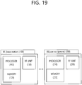
- FIG. 19 is a block diagram of a wireless apparatus in which the embodiments of the present invention is implemented.
- a base station 100 includes a processor 110, a memory 120 and a radio frequency (RF) unit 130.
- the processor 110 implements the proposed functions, processed, and/or methods.
- the memory 120 is connected to the processor 110 and configured to store various information used for the operations for the processor 110.
- the RF unit 130 is connected to the processor 110 and configured to transmit and/or receive a radio signal.
- a UE 200 includes a processor 210, a memory 220, and a RF unit 230.
- the processor 210 implements the proposed functions, processed, and/or methods.
- the memory 220 is connected to the processor 210 and configured to store various information used for the operations for the processor 210.
- the RF unit 230 is connected to the processor 210 and configured to transmit and/or receive a radio signal.
- the processor 110, 210 may include Application-Specific Integrated Circuits (ASICs), other chipsets, logic circuits, data processing devices and/or converters for mutually converting baseband signals and radio signals.
- the memory 120, 220 may include Read-Only Memory (ROM), Random Access Memory (RAM), flash memory, memory cards, storage media and/or other storage devices.
- the RF unit 130, 230 may include one or more antennas for transmitting and/or receiving radio signals.
- the above-described scheme may be implemented as a module (process, function, etc.) for performing the above-described function.
- the module may be stored in the memory 120, 220 and executed by the processor 110, 210.
- the memory 120, 220 may be placed inside or outside the processor 110, 210 and connected to the processor 110, 210 using a variety of well-known means.
Landscapes
- Engineering & Computer Science (AREA)
- Signal Processing (AREA)
- Computer Networks & Wireless Communication (AREA)
- Mobile Radio Communication Systems (AREA)
Claims (2)
- Procédé de détermination d'un horaire d'émission en liaison montante d'un équipement d'utilisateur qui est configuré avec une pluralité de cellules dans un système de communications sans fil, le procédé comprenant :la réception (S161) d'informations de configuration d'avance d'horaire, TA, depuis une station de base ; etla détermination (S162) d'un horaire d'émission en liaison montante pour chacune de deux cellules parmi la pluralité de cellules sur la base des informations de configuration de TA,dans lequel les deux cellules sont incluses dans un groupe, etdans lequel :i) lorsque les deux cellules comprennent une première cellule utilisant une structure de trame de duplexage par répartition en fréquences, FDD, et une seconde cellule utilisant une structure de trame de duplexage par répartition dans le temps, TDD, et lorsque le groupe inclut uniquement des cellules secondaires,
à la fois un horaire d'émission en liaison montante de la première cellule et un horaire d'émission en liaison montante de la seconde cellule sont déterminés par application d'une même valeur de décalage quelles que soient les structures de trame de la première cellule et de la seconde cellule et la même valeur de décalage est une valeur de décalage appliquée à une cellule utilisant la structure de trame TDD, etii) lorsque les deux cellules comprennent la première cellule utilisant la structure de trame FDD et la seconde cellule utilisant la structure de trame TDD et lorsque le groupe inclut une cellule primaire,un horaire d'émission en liaison montante de la cellule primaire est déterminé sur la base des informations de configuration de TA, et à la fois un horaire d'émission en liaison montante de la première cellule et un horaire d'émission en liaison montante de la seconde cellule sont déterminés pour être identique à l'horaire d'émission en liaison montante de la cellule primaire. - Procédé selon la revendication 1, dans lequel à la fois la première cellule et la seconde cellule sont des cellules secondaires.
Applications Claiming Priority (4)
| Application Number | Priority Date | Filing Date | Title |
|---|---|---|---|
| US201361875695P | 2013-09-10 | 2013-09-10 | |
| US201361906856P | 2013-11-20 | 2013-11-20 | |
| US201461930471P | 2014-01-22 | 2014-01-22 | |
| PCT/KR2014/008362 WO2015037880A1 (fr) | 2013-09-10 | 2014-09-05 | Procédé pour déterminer une heure de transmission en liaison montante d'un terminal configuré pour une pluralité de cellules dans un système de communications sans fil, et appareil utilisant le procédé |
Publications (3)
| Publication Number | Publication Date |
|---|---|
| EP3046377A1 EP3046377A1 (fr) | 2016-07-20 |
| EP3046377A4 EP3046377A4 (fr) | 2017-04-26 |
| EP3046377B1 true EP3046377B1 (fr) | 2020-04-01 |
Family
ID=52665927
Family Applications (1)
| Application Number | Title | Priority Date | Filing Date |
|---|---|---|---|
| EP14843461.6A Active EP3046377B1 (fr) | 2013-09-10 | 2014-09-05 | Procédé pour déterminer une heure de transmission en liaison montante d'un terminal configuré pour une pluralité de cellules dans un système de communications sans fil, et appareil utilisant le procédé |
Country Status (6)
| Country | Link |
|---|---|
| US (2) | US10117208B2 (fr) |
| EP (1) | EP3046377B1 (fr) |
| JP (1) | JP6174815B2 (fr) |
| KR (2) | KR20160048097A (fr) |
| CN (1) | CN105580457B (fr) |
| WO (1) | WO2015037880A1 (fr) |
Families Citing this family (31)
| Publication number | Priority date | Publication date | Assignee | Title |
|---|---|---|---|---|
| CN105519014B (zh) * | 2013-09-04 | 2018-11-02 | Lg电子株式会社 | 用于频分双工和时分双工的聚合的方法和设备 |
| US9860914B2 (en) * | 2014-02-10 | 2018-01-02 | Qualcomm Incorporated | Handling FDD and TDD timing offset in FDD and TDD CA in LTE |
| JP5970506B2 (ja) * | 2014-07-31 | 2016-08-17 | 株式会社Nttドコモ | ユーザ装置、及び上り送信タイミング制御方法 |
| JP6666918B2 (ja) * | 2015-08-07 | 2020-03-18 | パナソニック インテレクチュアル プロパティ コーポレーション オブ アメリカPanasonic Intellectual Property Corporation of America | 基地局、端末、送信方法及び受信方法 |
| TW201711430A (zh) * | 2015-09-15 | 2017-03-16 | Chunghwa Telecom Co Ltd | 無線後置網路頻段彈性配置之方法 |
| US10187864B2 (en) | 2016-04-01 | 2019-01-22 | Qualcomm Incorporated | Timing advance design for enhanced component carrier |
| EP3451732B1 (fr) * | 2016-04-28 | 2021-10-06 | Sharp Kabushiki Kaisha | Dispositif terminal, dispositif de station de base et procédés de communication |
| EP4236561A3 (fr) | 2016-07-13 | 2023-10-18 | Samsung Electronics Co., Ltd. | Terminal, station de base et procédés correspondants |
| CN107733550A (zh) * | 2016-08-11 | 2018-02-23 | 株式会社Ntt都科摩 | 指示和确定子帧的起始发送定时的方法、基站和用户设备 |
| CN111954272A (zh) * | 2016-09-28 | 2020-11-17 | 华为技术有限公司 | 一种数据传输的方法及设备 |
| US10652894B2 (en) * | 2016-11-11 | 2020-05-12 | Qualcomm Incorporated | Timing advance reporting for latency reduction |
| CN110392990B (zh) | 2017-01-08 | 2021-07-09 | Lg电子株式会社 | 用于控制交叉链路干扰的方法及其设备 |
| US10499386B2 (en) * | 2017-06-15 | 2019-12-03 | Sharp Kabushiki Kaisha | Procedure, base station and user equipment for uplink transmission without grant |
| US11032816B2 (en) * | 2017-08-10 | 2021-06-08 | Qualcomm Incorporated | Techniques and apparatuses for variable timing adjustment granularity |
| CN110140344B (zh) | 2017-09-26 | 2021-03-05 | 华为技术有限公司 | 一种通知消息的处理方法以及终端 |
| US11102777B2 (en) | 2017-11-10 | 2021-08-24 | Telefonaktiebolaget Lm Ericsson (Publ) | Timing advance offset for uplink-downlink switching in new radio |
| WO2019096273A1 (fr) * | 2017-11-17 | 2019-05-23 | 华为技术有限公司 | Procédé et dispositif d'émission et de réception d'informations |
| CN109802755B (zh) * | 2017-11-17 | 2021-12-17 | 华为技术有限公司 | 下行控制信息确定方法和通信装置 |
| CN110572877B (zh) * | 2017-11-17 | 2020-11-10 | 华为技术有限公司 | 一种信息发送、接收的方法及装置 |
| ES2929855T3 (es) * | 2018-01-09 | 2022-12-02 | Beijing Xiaomi Mobile Software Co Ltd | Procedimientos de capa física y de MAC en un dispositivo inalámbrico |
| JP7066748B2 (ja) * | 2018-01-12 | 2022-05-13 | 株式会社Nttドコモ | 端末、基地局、無線通信システム、及び上り送信タイミング調整方法 |
| KR102638627B1 (ko) | 2018-02-23 | 2024-02-21 | 삼성전자 주식회사 | 무선 통신 시스템에서 불연속 수신 수행 시 설정된 상향링크 데이터의 재전송을 수행하는 방법 및 장치 |
| KR102137253B1 (ko) | 2018-06-26 | 2020-07-23 | 국방과학연구소 | 기준 신호의 초기 타이밍 설정 방법 및 그 장치 |
| CN110662285B (zh) * | 2018-06-29 | 2022-11-08 | 中兴通讯股份有限公司 | 定时调整信息的配置方法及装置 |
| US11082941B2 (en) * | 2018-08-09 | 2021-08-03 | Qualcomm Incorporated | Timing offset techniques in wireless communications |
| AU2019351481A1 (en) * | 2018-09-27 | 2021-05-20 | FG Innovation Company Limited | User equipment and base stations that achieve ultra reliable and low latency communications |
| US11671890B2 (en) * | 2019-12-23 | 2023-06-06 | Qualcomm Incorporated | Timing advance group reporting for layer 1/layer 2-centric inter-cell mobility |
| US20220039125A1 (en) * | 2020-07-31 | 2022-02-03 | Qualcomm Incorporated | Wireless communication with a configurable gap |
| US20220085964A1 (en) * | 2020-09-15 | 2022-03-17 | Qualcomm Incorporated | Enhanced timing advance offset value indications |
| KR20230052131A (ko) * | 2021-10-12 | 2023-04-19 | 삼성전자주식회사 | 무선 통신 시스템에서 신호를 전송하기 위한 장치 및 방법 |
| US11832091B2 (en) * | 2021-12-16 | 2023-11-28 | Qualcomm Incorporated | Timing advance configuration for uplink communication resources |
Family Cites Families (16)
| Publication number | Priority date | Publication date | Assignee | Title |
|---|---|---|---|---|
| DE10009401C2 (de) * | 2000-02-28 | 2003-07-24 | Siemens Ag | Verfahren, Mobilfunksystem und Station zur Ermittlung einer Vorhaltezeit für eine Verbindung zwischen zwei Stationen |
| US8681666B2 (en) | 2007-10-01 | 2014-03-25 | Qualcomm Incorporated | Partial discarding of cyclic prefix for efficient TDD or half-duplex FDD operation |
| CN101572577B (zh) | 2008-04-30 | 2012-11-28 | 电信科学技术研究院 | 一种实现上行发送定时提前的方法和装置 |
| US8934459B2 (en) * | 2010-01-08 | 2015-01-13 | Interdigital Patent Holdings, Inc. | Maintaining time alignment with multiple uplink carriers |
| US8804586B2 (en) | 2010-01-11 | 2014-08-12 | Blackberry Limited | Control channel interference management and extended PDCCH for heterogeneous network |
| WO2012041422A2 (fr) * | 2010-09-30 | 2012-04-05 | Panasonic Corporation | Configuration d'avance de synchronisation pour de multiples porteuses composantes de liaison montante |
| CN103348746B (zh) * | 2011-02-11 | 2017-05-24 | 黑莓有限公司 | 时间提前的随机接入信道发送 |
| CN102118801B (zh) * | 2011-03-31 | 2013-07-24 | 电信科学技术研究院 | 多载波聚合系统中的上行传输方法和设备 |
| US8837304B2 (en) | 2011-04-08 | 2014-09-16 | Sharp Kabushiki Kaisha | Devices for multi-group communications |
| US8705467B2 (en) * | 2011-04-29 | 2014-04-22 | Nokia Corporation | Cross-carrier preamble responses |
| US9391758B2 (en) | 2011-05-06 | 2016-07-12 | Lg Electronics Inc. | Method and apparatus for adjusting transmission timing in wireless access system supporting carrier aggregation |
| US9204411B2 (en) * | 2011-09-12 | 2015-12-01 | Qualcomm Incorporated | Support of multiple timing advance groups for user equipment in carrier aggregation in LTE |
| CN103581918B (zh) * | 2012-07-31 | 2018-06-01 | 夏普株式会社 | 分量载波配置方法、基站和用户设备 |
| US9706568B2 (en) * | 2013-06-28 | 2017-07-11 | Texas Instruments Incorporated | Uplink control signaling for joint FDD and TDD carrier aggregation |
| CN104348603B (zh) * | 2013-07-30 | 2020-06-12 | 北京三星通信技术研究有限公司 | 配置上行传输定时的方法和设备 |
| CN106134272B (zh) * | 2015-01-30 | 2020-01-31 | 华为技术有限公司 | 通信方法、网络设备、用户设备和通信系统 |
-
2014
- 2014-09-05 WO PCT/KR2014/008362 patent/WO2015037880A1/fr active Application Filing
- 2014-09-05 CN CN201480049873.XA patent/CN105580457B/zh active Active
- 2014-09-05 JP JP2016542627A patent/JP6174815B2/ja active Active
- 2014-09-05 KR KR1020167005808A patent/KR20160048097A/ko active Application Filing
- 2014-09-05 KR KR1020177025328A patent/KR101832686B1/ko active IP Right Grant
- 2014-09-05 US US14/915,987 patent/US10117208B2/en active Active
- 2014-09-05 EP EP14843461.6A patent/EP3046377B1/fr active Active
-
2018
- 2018-10-04 US US16/151,799 patent/US10945228B2/en active Active
Non-Patent Citations (1)
| Title |
|---|
| None * |
Also Published As
| Publication number | Publication date |
|---|---|
| JP2016531531A (ja) | 2016-10-06 |
| KR20170105643A (ko) | 2017-09-19 |
| US20160219547A1 (en) | 2016-07-28 |
| EP3046377A4 (fr) | 2017-04-26 |
| JP6174815B2 (ja) | 2017-08-02 |
| US10117208B2 (en) | 2018-10-30 |
| EP3046377A1 (fr) | 2016-07-20 |
| US20190037514A1 (en) | 2019-01-31 |
| US10945228B2 (en) | 2021-03-09 |
| KR101832686B1 (ko) | 2018-02-26 |
| CN105580457B (zh) | 2019-09-10 |
| WO2015037880A1 (fr) | 2015-03-19 |
| KR20160048097A (ko) | 2016-05-03 |
| CN105580457A (zh) | 2016-05-11 |
Similar Documents
| Publication | Publication Date | Title |
|---|---|---|
| US10945228B2 (en) | Method for determining uplink transmission timing of terminal having plurality of cells configured therein in wireless communication system, and apparatus using the method | |
| US11652580B2 (en) | Method and apparatus for transmitting downlink control information in wireless communication system | |
| US10779271B2 (en) | Method and apparatus for decoding downlink control information by terminal in wireless communication system | |
| EP3657715B1 (fr) | Procédé et dispositif de transmission d'ack/nack dans un système de communication sans fil | |
| US10477546B2 (en) | Method and apparatus for communication for terminal in wireless communication system | |
| EP3054616B1 (fr) | Procédé de transmission par un terminal d'ack/nack dans un système de communication sans fil et dispositif correspondant |
Legal Events
| Date | Code | Title | Description |
|---|---|---|---|
| PUAI | Public reference made under article 153(3) epc to a published international application that has entered the european phase |
Free format text: ORIGINAL CODE: 0009012 |
|
| 17P | Request for examination filed |
Effective date: 20160331 |
|
| AK | Designated contracting states |
Kind code of ref document: A1 Designated state(s): AL AT BE BG CH CY CZ DE DK EE ES FI FR GB GR HR HU IE IS IT LI LT LU LV MC MK MT NL NO PL PT RO RS SE SI SK SM TR |
|
| AX | Request for extension of the european patent |
Extension state: BA ME |
|
| DAX | Request for extension of the european patent (deleted) | ||
| A4 | Supplementary search report drawn up and despatched |
Effective date: 20170328 |
|
| RIC1 | Information provided on ipc code assigned before grant |
Ipc: H04W 56/00 20090101AFI20170322BHEP Ipc: H04B 7/26 20060101ALI20170322BHEP |
|
| STAA | Information on the status of an ep patent application or granted ep patent |
Free format text: STATUS: EXAMINATION IS IN PROGRESS |
|
| 17Q | First examination report despatched |
Effective date: 20180914 |
|
| GRAP | Despatch of communication of intention to grant a patent |
Free format text: ORIGINAL CODE: EPIDOSNIGR1 |
|
| STAA | Information on the status of an ep patent application or granted ep patent |
Free format text: STATUS: GRANT OF PATENT IS INTENDED |
|
| INTG | Intention to grant announced |
Effective date: 20191011 |
|
| GRAS | Grant fee paid |
Free format text: ORIGINAL CODE: EPIDOSNIGR3 |
|
| GRAA | (expected) grant |
Free format text: ORIGINAL CODE: 0009210 |
|
| STAA | Information on the status of an ep patent application or granted ep patent |
Free format text: STATUS: THE PATENT HAS BEEN GRANTED |
|
| AK | Designated contracting states |
Kind code of ref document: B1 Designated state(s): AL AT BE BG CH CY CZ DE DK EE ES FI FR GB GR HR HU IE IS IT LI LT LU LV MC MK MT NL NO PL PT RO RS SE SI SK SM TR |
|
| REG | Reference to a national code |
Ref country code: GB Ref legal event code: FG4D |
|
| REG | Reference to a national code |
Ref country code: AT Ref legal event code: REF Ref document number: 1253013 Country of ref document: AT Kind code of ref document: T Effective date: 20200415 Ref country code: CH Ref legal event code: EP |
|
| REG | Reference to a national code |
Ref country code: DE Ref legal event code: R096 Ref document number: 602014063281 Country of ref document: DE |
|
| REG | Reference to a national code |
Ref country code: IE Ref legal event code: FG4D |
|
| REG | Reference to a national code |
Ref country code: NL Ref legal event code: FP |
|
| PG25 | Lapsed in a contracting state [announced via postgrant information from national office to epo] |
Ref country code: BG Free format text: LAPSE BECAUSE OF FAILURE TO SUBMIT A TRANSLATION OF THE DESCRIPTION OR TO PAY THE FEE WITHIN THE PRESCRIBED TIME-LIMIT Effective date: 20200701 |
|
| REG | Reference to a national code |
Ref country code: LT Ref legal event code: MG4D |
|
| PG25 | Lapsed in a contracting state [announced via postgrant information from national office to epo] |
Ref country code: LT Free format text: LAPSE BECAUSE OF FAILURE TO SUBMIT A TRANSLATION OF THE DESCRIPTION OR TO PAY THE FEE WITHIN THE PRESCRIBED TIME-LIMIT Effective date: 20200401 Ref country code: PT Free format text: LAPSE BECAUSE OF FAILURE TO SUBMIT A TRANSLATION OF THE DESCRIPTION OR TO PAY THE FEE WITHIN THE PRESCRIBED TIME-LIMIT Effective date: 20200817 Ref country code: CZ Free format text: LAPSE BECAUSE OF FAILURE TO SUBMIT A TRANSLATION OF THE DESCRIPTION OR TO PAY THE FEE WITHIN THE PRESCRIBED TIME-LIMIT Effective date: 20200401 Ref country code: FI Free format text: LAPSE BECAUSE OF FAILURE TO SUBMIT A TRANSLATION OF THE DESCRIPTION OR TO PAY THE FEE WITHIN THE PRESCRIBED TIME-LIMIT Effective date: 20200401 Ref country code: SE Free format text: LAPSE BECAUSE OF FAILURE TO SUBMIT A TRANSLATION OF THE DESCRIPTION OR TO PAY THE FEE WITHIN THE PRESCRIBED TIME-LIMIT Effective date: 20200401 Ref country code: IS Free format text: LAPSE BECAUSE OF FAILURE TO SUBMIT A TRANSLATION OF THE DESCRIPTION OR TO PAY THE FEE WITHIN THE PRESCRIBED TIME-LIMIT Effective date: 20200801 Ref country code: GR Free format text: LAPSE BECAUSE OF FAILURE TO SUBMIT A TRANSLATION OF THE DESCRIPTION OR TO PAY THE FEE WITHIN THE PRESCRIBED TIME-LIMIT Effective date: 20200702 Ref country code: NO Free format text: LAPSE BECAUSE OF FAILURE TO SUBMIT A TRANSLATION OF THE DESCRIPTION OR TO PAY THE FEE WITHIN THE PRESCRIBED TIME-LIMIT Effective date: 20200701 |
|
| REG | Reference to a national code |
Ref country code: AT Ref legal event code: MK05 Ref document number: 1253013 Country of ref document: AT Kind code of ref document: T Effective date: 20200401 |
|
| PG25 | Lapsed in a contracting state [announced via postgrant information from national office to epo] |
Ref country code: RS Free format text: LAPSE BECAUSE OF FAILURE TO SUBMIT A TRANSLATION OF THE DESCRIPTION OR TO PAY THE FEE WITHIN THE PRESCRIBED TIME-LIMIT Effective date: 20200401 Ref country code: LV Free format text: LAPSE BECAUSE OF FAILURE TO SUBMIT A TRANSLATION OF THE DESCRIPTION OR TO PAY THE FEE WITHIN THE PRESCRIBED TIME-LIMIT Effective date: 20200401 Ref country code: HR Free format text: LAPSE BECAUSE OF FAILURE TO SUBMIT A TRANSLATION OF THE DESCRIPTION OR TO PAY THE FEE WITHIN THE PRESCRIBED TIME-LIMIT Effective date: 20200401 |
|
| PG25 | Lapsed in a contracting state [announced via postgrant information from national office to epo] |
Ref country code: AL Free format text: LAPSE BECAUSE OF FAILURE TO SUBMIT A TRANSLATION OF THE DESCRIPTION OR TO PAY THE FEE WITHIN THE PRESCRIBED TIME-LIMIT Effective date: 20200401 |
|
| REG | Reference to a national code |
Ref country code: DE Ref legal event code: R097 Ref document number: 602014063281 Country of ref document: DE |
|
| PG25 | Lapsed in a contracting state [announced via postgrant information from national office to epo] |
Ref country code: RO Free format text: LAPSE BECAUSE OF FAILURE TO SUBMIT A TRANSLATION OF THE DESCRIPTION OR TO PAY THE FEE WITHIN THE PRESCRIBED TIME-LIMIT Effective date: 20200401 Ref country code: SM Free format text: LAPSE BECAUSE OF FAILURE TO SUBMIT A TRANSLATION OF THE DESCRIPTION OR TO PAY THE FEE WITHIN THE PRESCRIBED TIME-LIMIT Effective date: 20200401 Ref country code: DK Free format text: LAPSE BECAUSE OF FAILURE TO SUBMIT A TRANSLATION OF THE DESCRIPTION OR TO PAY THE FEE WITHIN THE PRESCRIBED TIME-LIMIT Effective date: 20200401 Ref country code: IT Free format text: LAPSE BECAUSE OF FAILURE TO SUBMIT A TRANSLATION OF THE DESCRIPTION OR TO PAY THE FEE WITHIN THE PRESCRIBED TIME-LIMIT Effective date: 20200401 Ref country code: EE Free format text: LAPSE BECAUSE OF FAILURE TO SUBMIT A TRANSLATION OF THE DESCRIPTION OR TO PAY THE FEE WITHIN THE PRESCRIBED TIME-LIMIT Effective date: 20200401 Ref country code: AT Free format text: LAPSE BECAUSE OF FAILURE TO SUBMIT A TRANSLATION OF THE DESCRIPTION OR TO PAY THE FEE WITHIN THE PRESCRIBED TIME-LIMIT Effective date: 20200401 Ref country code: ES Free format text: LAPSE BECAUSE OF FAILURE TO SUBMIT A TRANSLATION OF THE DESCRIPTION OR TO PAY THE FEE WITHIN THE PRESCRIBED TIME-LIMIT Effective date: 20200401 |
|
| PLBE | No opposition filed within time limit |
Free format text: ORIGINAL CODE: 0009261 |
|
| STAA | Information on the status of an ep patent application or granted ep patent |
Free format text: STATUS: NO OPPOSITION FILED WITHIN TIME LIMIT |
|
| PG25 | Lapsed in a contracting state [announced via postgrant information from national office to epo] |
Ref country code: PL Free format text: LAPSE BECAUSE OF FAILURE TO SUBMIT A TRANSLATION OF THE DESCRIPTION OR TO PAY THE FEE WITHIN THE PRESCRIBED TIME-LIMIT Effective date: 20200401 Ref country code: SK Free format text: LAPSE BECAUSE OF FAILURE TO SUBMIT A TRANSLATION OF THE DESCRIPTION OR TO PAY THE FEE WITHIN THE PRESCRIBED TIME-LIMIT Effective date: 20200401 |
|
| 26N | No opposition filed |
Effective date: 20210112 |
|
| PG25 | Lapsed in a contracting state [announced via postgrant information from national office to epo] |
Ref country code: MC Free format text: LAPSE BECAUSE OF FAILURE TO SUBMIT A TRANSLATION OF THE DESCRIPTION OR TO PAY THE FEE WITHIN THE PRESCRIBED TIME-LIMIT Effective date: 20200401 |
|
| REG | Reference to a national code |
Ref country code: CH Ref legal event code: PL |
|
| PG25 | Lapsed in a contracting state [announced via postgrant information from national office to epo] |
Ref country code: SI Free format text: LAPSE BECAUSE OF FAILURE TO SUBMIT A TRANSLATION OF THE DESCRIPTION OR TO PAY THE FEE WITHIN THE PRESCRIBED TIME-LIMIT Effective date: 20200401 |
|
| REG | Reference to a national code |
Ref country code: BE Ref legal event code: MM Effective date: 20200930 |
|
| PG25 | Lapsed in a contracting state [announced via postgrant information from national office to epo] |
Ref country code: LU Free format text: LAPSE BECAUSE OF NON-PAYMENT OF DUE FEES Effective date: 20200905 |
|
| PG25 | Lapsed in a contracting state [announced via postgrant information from national office to epo] |
Ref country code: BE Free format text: LAPSE BECAUSE OF NON-PAYMENT OF DUE FEES Effective date: 20200930 Ref country code: CH Free format text: LAPSE BECAUSE OF NON-PAYMENT OF DUE FEES Effective date: 20200930 Ref country code: LI Free format text: LAPSE BECAUSE OF NON-PAYMENT OF DUE FEES Effective date: 20200930 Ref country code: IE Free format text: LAPSE BECAUSE OF NON-PAYMENT OF DUE FEES Effective date: 20200905 |
|
| PG25 | Lapsed in a contracting state [announced via postgrant information from national office to epo] |
Ref country code: TR Free format text: LAPSE BECAUSE OF FAILURE TO SUBMIT A TRANSLATION OF THE DESCRIPTION OR TO PAY THE FEE WITHIN THE PRESCRIBED TIME-LIMIT Effective date: 20200401 Ref country code: MT Free format text: LAPSE BECAUSE OF FAILURE TO SUBMIT A TRANSLATION OF THE DESCRIPTION OR TO PAY THE FEE WITHIN THE PRESCRIBED TIME-LIMIT Effective date: 20200401 Ref country code: CY Free format text: LAPSE BECAUSE OF FAILURE TO SUBMIT A TRANSLATION OF THE DESCRIPTION OR TO PAY THE FEE WITHIN THE PRESCRIBED TIME-LIMIT Effective date: 20200401 |
|
| PG25 | Lapsed in a contracting state [announced via postgrant information from national office to epo] |
Ref country code: MK Free format text: LAPSE BECAUSE OF FAILURE TO SUBMIT A TRANSLATION OF THE DESCRIPTION OR TO PAY THE FEE WITHIN THE PRESCRIBED TIME-LIMIT Effective date: 20200401 |
|
| P01 | Opt-out of the competence of the unified patent court (upc) registered |
Effective date: 20230524 |
|
| PGFP | Annual fee paid to national office [announced via postgrant information from national office to epo] |
Ref country code: NL Payment date: 20230808 Year of fee payment: 10 |
|
| PGFP | Annual fee paid to national office [announced via postgrant information from national office to epo] |
Ref country code: GB Payment date: 20230807 Year of fee payment: 10 |
|
| PGFP | Annual fee paid to national office [announced via postgrant information from national office to epo] |
Ref country code: FR Payment date: 20230807 Year of fee payment: 10 Ref country code: DE Payment date: 20230807 Year of fee payment: 10 |