EP3045645A1 - Antriebseinrichtung für einen flügel eines fensters oder einer tür - Google Patents
Antriebseinrichtung für einen flügel eines fensters oder einer tür Download PDFInfo
- Publication number
- EP3045645A1 EP3045645A1 EP16151004.5A EP16151004A EP3045645A1 EP 3045645 A1 EP3045645 A1 EP 3045645A1 EP 16151004 A EP16151004 A EP 16151004A EP 3045645 A1 EP3045645 A1 EP 3045645A1
- Authority
- EP
- European Patent Office
- Prior art keywords
- wing
- drive device
- drive
- frame
- spring
- Prior art date
- Legal status (The legal status is an assumption and is not a legal conclusion. Google has not performed a legal analysis and makes no representation as to the accuracy of the status listed.)
- Granted
Links
Images

Classifications
-
- E—FIXED CONSTRUCTIONS
- E05—LOCKS; KEYS; WINDOW OR DOOR FITTINGS; SAFES
- E05F—DEVICES FOR MOVING WINGS INTO OPEN OR CLOSED POSITION; CHECKS FOR WINGS; WING FITTINGS NOT OTHERWISE PROVIDED FOR, CONCERNED WITH THE FUNCTIONING OF THE WING
- E05F15/00—Power-operated mechanisms for wings
- E05F15/60—Power-operated mechanisms for wings using electrical actuators
- E05F15/603—Power-operated mechanisms for wings using electrical actuators using rotary electromotors
- E05F15/611—Power-operated mechanisms for wings using electrical actuators using rotary electromotors for swinging wings
- E05F15/616—Power-operated mechanisms for wings using electrical actuators using rotary electromotors for swinging wings operated by push-pull mechanisms
- E05F15/619—Power-operated mechanisms for wings using electrical actuators using rotary electromotors for swinging wings operated by push-pull mechanisms using flexible or rigid rack-and-pinion arrangements
-
- E—FIXED CONSTRUCTIONS
- E05—LOCKS; KEYS; WINDOW OR DOOR FITTINGS; SAFES
- E05F—DEVICES FOR MOVING WINGS INTO OPEN OR CLOSED POSITION; CHECKS FOR WINGS; WING FITTINGS NOT OTHERWISE PROVIDED FOR, CONCERNED WITH THE FUNCTIONING OF THE WING
- E05F15/00—Power-operated mechanisms for wings
- E05F15/60—Power-operated mechanisms for wings using electrical actuators
- E05F15/603—Power-operated mechanisms for wings using electrical actuators using rotary electromotors
- E05F15/611—Power-operated mechanisms for wings using electrical actuators using rotary electromotors for swinging wings
- E05F15/616—Power-operated mechanisms for wings using electrical actuators using rotary electromotors for swinging wings operated by push-pull mechanisms
-
- E—FIXED CONSTRUCTIONS
- E05—LOCKS; KEYS; WINDOW OR DOOR FITTINGS; SAFES
- E05Y—INDEXING SCHEME ASSOCIATED WITH SUBCLASSES E05D AND E05F, RELATING TO CONSTRUCTION ELEMENTS, ELECTRIC CONTROL, POWER SUPPLY, POWER SIGNAL OR TRANSMISSION, USER INTERFACES, MOUNTING OR COUPLING, DETAILS, ACCESSORIES, AUXILIARY OPERATIONS NOT OTHERWISE PROVIDED FOR, APPLICATION THEREOF
- E05Y2201/00—Constructional elements; Accessories therefor
- E05Y2201/40—Motors; Magnets; Springs; Weights; Accessories therefor
- E05Y2201/43—Motors
-
- E—FIXED CONSTRUCTIONS
- E05—LOCKS; KEYS; WINDOW OR DOOR FITTINGS; SAFES
- E05Y—INDEXING SCHEME ASSOCIATED WITH SUBCLASSES E05D AND E05F, RELATING TO CONSTRUCTION ELEMENTS, ELECTRIC CONTROL, POWER SUPPLY, POWER SIGNAL OR TRANSMISSION, USER INTERFACES, MOUNTING OR COUPLING, DETAILS, ACCESSORIES, AUXILIARY OPERATIONS NOT OTHERWISE PROVIDED FOR, APPLICATION THEREOF
- E05Y2600/00—Mounting or coupling arrangements for elements provided for in this subclass
- E05Y2600/10—Adjustable
-
- E—FIXED CONSTRUCTIONS
- E05—LOCKS; KEYS; WINDOW OR DOOR FITTINGS; SAFES
- E05Y—INDEXING SCHEME ASSOCIATED WITH SUBCLASSES E05D AND E05F, RELATING TO CONSTRUCTION ELEMENTS, ELECTRIC CONTROL, POWER SUPPLY, POWER SIGNAL OR TRANSMISSION, USER INTERFACES, MOUNTING OR COUPLING, DETAILS, ACCESSORIES, AUXILIARY OPERATIONS NOT OTHERWISE PROVIDED FOR, APPLICATION THEREOF
- E05Y2600/00—Mounting or coupling arrangements for elements provided for in this subclass
- E05Y2600/10—Adjustable
- E05Y2600/30—Adjustment motion
- E05Y2600/32—Rotary motion
-
- E—FIXED CONSTRUCTIONS
- E05—LOCKS; KEYS; WINDOW OR DOOR FITTINGS; SAFES
- E05Y—INDEXING SCHEME ASSOCIATED WITH SUBCLASSES E05D AND E05F, RELATING TO CONSTRUCTION ELEMENTS, ELECTRIC CONTROL, POWER SUPPLY, POWER SIGNAL OR TRANSMISSION, USER INTERFACES, MOUNTING OR COUPLING, DETAILS, ACCESSORIES, AUXILIARY OPERATIONS NOT OTHERWISE PROVIDED FOR, APPLICATION THEREOF
- E05Y2900/00—Application of doors, windows, wings or fittings thereof
- E05Y2900/10—Application of doors, windows, wings or fittings thereof for buildings or parts thereof
- E05Y2900/13—Type of wing
- E05Y2900/148—Windows
Definitions
- the invention relates to a drive device for a wing of a window or door mounted in a steerable manner on a frame according to the preamble of claim 1.
- Such a drive device is from the DE 20 2008 004 024 U1 known.
- the drive is held on a one-armed lever, which in turn is articulated on a pivot axis which is held by a bracket attached to the sash frame.
- the drive When opening the wing, i. when stretching the traction device, the drive is pivoted out of its position adjacent to the wing, so that the rectilinear traction means, which is held with its other end on the frame, undergoes a disability-free stretch.
- the invention has for its object to further develop a drive device of the generic type so that its usability extended, increased their reliability and their life is extended.
- a leg spring is provided for applying the spring force, which engages on the one hand in the lever carrying the drive and on the other hand in the console connected to the wing or on the frame.
- the lever and the console are connected to each other by a pivot axis, wherein the console is fixed, for example by means of a sliding block in an undercut groove of the wing.
- leg spring which is also known under the term wrap
- another suitable spring for example, a coil spring in the form of a tension or compression spring, a leaf or a torsion spring may be provided, which pulls the drive or the lever carrying it in the direction of the wing or frame.
- leg spring is configured so that the resulting torque increases in the event of an opening-related pivoting of the lever, whereby the drive is reliably pressed in the direction of the end position, that is to say for engagement with the wing or frame.
- both components are kept at a defined distance from each other, including, as provided for a further aspect of the invention, a spacer sleeve is provided, preferably on the pivot axis, this enveloping, guided.
- the invention now also makes it possible to use the drive device in the case of particularly narrow rotary vane elements, the suitability also contributing to the use of a push chain as the traction means, which is deflected in an arc shape when the vane is opened and closed.
- the push chain with a defined voltage is pressed transversely to the winding direction in the arch shape by the spring, so that there is a defined position of the pivoted wing and collisions with design and fitting parts are avoided.
- the elasticity of the spring prevents overloading of the traction means on the drive housing, so that this remains substantially unimpaired.
- a wing 3 of a door which is held pivotably on a window frame 1, is shown, the window frame 1 having frame frame spars 2 and the wing 3 wing frame spars 4.
- the wing 3 may also be part of a window or a facade element.
- a drive device which has an electric drive 5, with which a traction means 6, in particular in the form of a push chain, is movable, wherein a pinion of the drive 5 is in engagement with the traction means 6.
- the traction means 6 is hinged to the frame 1 and the associated frame spar 2 by means of a pivoting flap 14 attached thereto.
- the push chain is bent transversely to the winding direction arcuately.
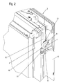
- FIG. 2 which depicts an enlarged partial section of the wing 3, it can be seen that the drive 5 is pivotally mounted on the wing 3, to which a pivoting device 7 is provided with a bracket 9 and a lever 8, which is arranged at a distance to the drive 5 pivot axis 10th is stored, as well as the console.
- a pivoting device 7 is provided with a bracket 9 and a lever 8, which is arranged at a distance to the drive 5 pivot axis 10th is stored, as well as the console.
- the one-armed lever 8 by means of a screw 16 ( Fig. 5 ) attached to the drive 5, which, as in the FIG. 1 can be seen, is connected in the opposite end in the same way at a further pivoting device 7.
- the drive 5 is spring-loaded pivotally held about the pivot axis 10 arranged at a distance thereto.
- the spring force is applied by a leg spring 11, which is guided on the pivot axis 10 and which engages with a leg in the bracket 9 and with the other leg in the one-armed lever 8.
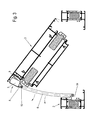
- the drive 5 When opening the wing 3, the drive 5 is pivoted into an end position while maintaining the arcuate course of the traction means 6, in a position as shown in the FIG. 3 can be seen, the drive 5 is lifted by the pivoting of the lever 8 from the wing 3.
- the lever 8 When closing the wing 3, the lever 8 is pivoted by the leg spring 11 in the direction of the wing 3 and the wing frame spar 4, the traction means 6 with a defined voltage initially retains its arc shape, as in the FIG. 3 can be seen, in which the beginning of the closing operation or the end of the opening process is shown.
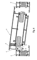
- FIG. 4 Finally, a nearly closed position of the wing 3 again.
- the drive 5 is under spring tension at the bottom of a formed frame of the sash 4.
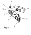
- a pivoting device 7 is shown as a detail. It can be seen that a spacer sleeve 15 is guided on the pivot axis 10, on which in turn the leg spring 11 is mounted. This spacer sleeve 15 acts as a spacer between the lever 8 and the bracket 9, so that a hooking of both components is avoided.
Landscapes
- Power-Operated Mechanisms For Wings (AREA)
- Closing And Opening Devices For Wings, And Checks For Wings (AREA)
Abstract
Description
- Die Erfindung betrifft eine Antriebseinrichtung für einen lenkbar an einem Blendrahmen gelagerten Flügel eines Fensters oder einer Tür nach dem Oberbegriff des Anspruchs 1.
- Eine derartige Antriebseinrichtung ist aus der
DE 20 2008 004 024 U1 bekannt. Darin ist ein Zugmitteltrieb offenbart, bestehend aus einem an einem Flügelrahmen angeordneten elektrischen Antrieb sowie einem Zugmittel, das aus einer geradlinig geführten Kette besteht. - Der Antrieb ist dabei an einem einarmigen Hebel gehalten, der wiederum an einer Schwenkachse angelenkt ist, die von einer am Flügelrahmen befestigten Konsole gehalten ist.
- Beim Öffnen des Flügels, d.h. bei Streckung des Zugmittels, wird der Antrieb aus seiner am Flügel anliegenden Position herausgeschwenkt, so dass das geradlinig verlaufende Zugmittel, das mit seinem anderen Ende am Blendrahmen gehalten ist, eine behinderungsfreie Streckung erfährt.
- Prinzipiell hat sich diese Konstruktion bewährt. Allerdings ist ihr Einsatzgebiet insoweit eingeschränkt, als sie für besonders schmale Drehflügelelemente nicht realisiert werden kann, da die Öffnungskinematik zu Kollisionen mit anderen Bauteilen des Systems führt, die letztendlich eine Einschränkung der Funktionsfähigkeit mit sich bringen.
- In der
DE 10 2006 013 332 A1 ist eine Antriebseinrichtung thematisiert, bei der der Antrieb fest mit dem Flügel verbunden ist. Dabei erfolgt die Streckung des Zugmittels in einem definierten Seitenbogen, wodurch zwar eine Kollision beim Verschwenken mit benachbarten Bauteilen vermieden wird, jedoch führt die starre Anbindung des Antriebs am Flügel zu hohen Biegespannungen am Abtriebsrad des Antriebs, aus denen sich Probleme hinsichtlich der Dauerfestigkeit des Antriebs insgesamt ergeben. Die geforderte und gewünschte Standzeit ist damit nicht erreichbar. - Im Übrigen kann es durch den fehlenden Zwang zur definierten Positionierung des den Antrieb tragenden Hebels beim Schließen des Flügels zu Kollisionen des Antriebs am Blendrahmen kommen, die zu einem erhöhten Verschleiß der beteiligten Funktionsteile führen und die Funktionssicherheit der Antriebseinrichtung beeinträchtigen können.
- Der Erfindung liegt die Aufgabe zugrunde, eine Antriebseinrichtung der gattungsgemäßen Art so weiterzuentwickeln, dass ihre Verwendbarkeit erweitert, ihre Funktionssicherheit erhöht und ihre Standzeit verlängert wird.
- Diese Aufgabe wird durch eine Antriebseinrichtung mit den Merkmalen des Anspruchs 1 gelöst.
- Durch diese konstruktive Ausbildung der Antriebseinrichtung ergeben sich eine ganze Reihe von Vorteilen. So wird gegenüber einer sozusagen federfreien Verschwenkung des Antriebs nach dem Stand der Technik die Funktionssicherheit deutlich erhöht, indem der Antrieb beim Verschließen des Flügels durch ein über eine eingesetzte Feder wirkendes Drehmoment in eine Beschlagnut eines Rahmenholms gedrückt wird. D.h., der Antrieb nimmt in jeder Endposition, im beschriebenen Fall bei geschlossenem Flügel, eine definierte feste Position ein.
- Da der Antrieb federbelastet am Rahmenholm anliegt, ist eine wie auch immer geartete Bewegung, die ein Klappergeräusch erzeugen könnte, praktisch ausgeschlossen. Gegenüber dem Stand der Technik stellt dies eine auch akustische Verbesserung dar. Hierzu gehört auch eine sich ergebende geringere Schwingungsübertragung vom Antrieb auf den Flügel.
- Gegenüber der einen zum Stand der Technik beschriebenen Konstruktion, nach der der Antrieb starr, d.h. nicht schwenkbar gehalten ist, ergibt sich eine wesentlich höhere Standzeit des Antriebs, insbesondere des Antriebsgehäuses, da in Schwenkfunktion auftretende Belastungen, insbesondere Spannungen, durch die eingesetzte Feder abgebaut werden.
- Nach einer vorteilhaften Weiterbildung der Erfindung ist zur Aufbringung der Federkraft eine Schenkelfeder vorgesehen, die einerseits in den den Antrieb tragenden Hebel und andererseits in die am Flügel oder am Blendrahmen angeschlossene Konsole eingreift.
- Dabei sind der Hebel und die Konsole durch eine Schwenkachse miteinander verbunden, wobei die Konsole beispielsweise mittels eines Nutensteins in einer hinterschnittenen Nut des Flügels befestigt ist.
- Anstelle einer Schenkelfeder, die auch unter dem Begriff Schlingfeder bekannt ist, kann auch eine andere geeignete Feder, z. B. eine Schraubenfeder in Form einer Zug- oder Druckfeder, eine Blatt- oder eine Torsionsfeder vorgesehen sein, die den Antrieb bzw. den diesen tragenden Hebel in Richtung des Flügels oder Blendrahmens zieht.
- Die genannte Schenkelfeder ist so konfiguriert, dass bei einem öffnungsbedingten Ausschwenken des Hebels das sich ergebende Drehmoment zunimmt, wodurch der Antrieb zuverlässig in die Richtung der Endstandsposition, sprich zur Anlage am Flügel oder Blendrahmen gedrückt wird.
- Zur Vermeidung eines Verhakens des Hebels und der Konsole, an denen die Schenkelfeder befestigt ist, werden beide Bauteile in einem definierten Abstand zueinander gehalten, wozu, wie nach einem weiteren Gedanken der Erfindung vorgesehen, eine Distanzhülse vorgesehen ist, die bevorzugt auf der Schwenkachse, diese umhüllend, geführt ist.
- Die Erfindung ermöglicht nun auch den Einsatz der Antriebseinrichtung bei besonders schmalen Drehflügelelementen, wobei zur Eignung auch beiträgt, dass als Zugmittel eine Schubkette eingesetzt wird, die beim Öffnen und Schließen des Flügels bogenförmig ausgelenkt ist. Dabei wird durch die Feder die Schubkette mit einer definierten Spannung quer zur Wickelrichtung in die Bogenform gedrückt, so dass sich eine definierte Position des verschwenkten Flügels ergibt und Kollisionen mit Konstruktions- und Beschlagteilen vermieden werden.
- Darüber hinaus verhindert die Elastizität der Feder eine Überlastung des Zugmittels am Antriebsgehäuse, so dass dies im Wesentlichen unbeeinträchtigt bleibt.
- Weitere vorteilhafte Ausbildungen sind in den Unteransprüchen gekennzeichnet.
- Ein Ausführungsbeispiel der Erfindung wird nachfolgend anhand der beigefügten Zeichnungen beschrieben.
- Es zeigen:
- Figur 1
- einen Teilausschnitt einer mit einer erfindungsgemäßen Antriebseinrichtung versehenen Tür in einer schematischen Ansicht
- Figur 2
- einen vergrößerten Ausschnitt der Tür entsprechend der Kennzeichnung II in
Fig. 1 - Figur 3
- einen Querschnitt durch die geöffnete Tür in einer schematischen Darstellung
- Figur 4
- den Querschnitt nach
Fig. 3 in einer weitgehend geschlossenen Stellung der Tür - Figur 5
- eine Einzelheit der Antriebsvorrichtung in einer perspektivischen Ansicht.
- In der
Figur 1 ist ein an einem Blendrahmen 1 verschwenkbar gehaltener Flügel 3 einer Tür dargestellt, wobei der Blendrahmen 1 Blendrahmenholme 2 und der Flügel 3 Flügelrahmenholme 4 aufweist. Anstelle einer Tür kann der Flügel 3 auch Bestandteil eines Fensters oder eines Fassadenelementes sein. - An einem Flügelrahmenholm 4 ist eine Antriebseinrichtung befestigt, die einen elektrischen Antrieb 5 aufweist, mit dem ein Zugmittel 6, insbesondere in Form einer Schubkette, bewegbar ist, wobei ein Ritzel des Antriebs 5 mit dem Zugmittel 6 in Eingriff steht. Andererseits ist das Zugmittel 6 am Blendrahmen 1 bzw. dem zugeordneten Blendrahmenholm 2 mittels einer daran befestigten Schwenklasche 14 angelenkt. Die Schubkette ist dabei quer zur Wickelrichtung bogenförmig auslenkbar.
- In der
Figur 2 , die einen vergrößerten Teilausschnitt des Flügels 3 abbildet, ist erkennbar, dass der Antrieb 5 verschwenkbar am Flügel 3 befestigt ist, wozu eine Schwenkvorrichtung 7 vorgesehen ist, mit einer Konsole 9 und einem Hebel 8, der an einer abständig zum Antrieb 5 angeordneten Schwenkachse 10 gelagert ist, ebenso wie die Konsole 9. - Diese ist fest mit dem Flügel 3 verbunden und zwar mittels eine in eine hinterschnittene Nut des Flügelrahmenholms 4 eingreifenden Nutsteins 13.
- Der einarmige Hebel 8 hingegen ist mittels einer Schraube 16 (
Fig. 5 ) am Antrieb 5 befestigt, der, wie in derFigur 1 erkennbar ist, im gegenüberliegenden Endbereich in gleicher Weise an einer weiteren Schwenkeinrichtung 7 angeschlossen ist. - Erfindungsgemäß ist der Antrieb 5 federbelastet schwenkbar um die abständig dazu angeordnete Schwenkachse 10 gehalten. Die Federkraft wird durch eine Schenkelfeder 11 aufgebracht, die auf der Schwenkachse 10 geführt ist und die mit einem Schenkel in die Konsole 9 und mit dem anderen Schenkel in den einarmigen Hebel 8 eingreift.
- Beim Öffnen des Flügels 3 wird unter Beibehaltung des bogenförmigen Verlaufs des Zugmittels 6 der Antrieb 5 in eine Endstellung verschwenkt, in eine Position, wie sie in der
Figur 3 erkennbar ist, wobei der Antrieb 5 durch die Verschwenkung des Hebels 8 vom Flügel 3 abgehoben ist. - Beim Schließen des Flügels 3 wird der Hebel 8 durch die Schenkelfeder 11 in Richtung des Flügels 3 bzw. des Flügelrahmenholms 4 verschwenkt, wobei das Zugmittel 6 mit einer definierten Spannung zunächst seine Bogenform beibehält, wie sie in der
Figur 3 zu erkennen ist, in der der Beginn des Schließvorgangs bzw. das Ende des Öffnungsvorganges abgebildet ist. Dabei verläuft das Zugmittel 6, bezogen auf den Flügel 3, konvex bogenförmig. - Die
Figur 4 schließlich gibt eine nahezu geschlossene Stellung des Flügels 3 wieder. Dabei liegt der Antrieb 5 unter Federspannung am Grund eines gebildeten Rahmen des Flügelrahmenholms 4. - Durch die Pressung des Antriebs 5 an den Grund des Falzes des Flügels 3 ist eine ausreichende Arretierung des Antriebs 5 in dieser Endstellung gewährleistet, woraus sich eine hohe Funktionssicherheit ergibt, insbesondere da eine Kollision des Antriebs 5 mit dem Blendrahmenholm 2 ausgeschlossen ist.
- In der
Figur 5 ist eine Schwenkvorrichtung 7 als Einzelheit dargestellt. Darin ist zu erkennen, dass auf der Schwenkachse 10 eine Distanzhülse 15 geführt ist, auf der wiederum die Schenkelfeder 11 gelagert ist. Diese Distanzhülse 15 fungiert als Abstandshalter zwischen dem Hebel 8 und der Konsole 9, so dass ein Verhaken beider Bauteile vermieden wird.
Claims (13)
- Antriebseinrichtung für einen verschwenkbar an einem Blendrahmen (1) gelagerten Flügel (3) eines Fensters oder einer Tür, mit einem in Schließstellung des Flügels (3) verdeckt zwischen dem Blendrahmen (1) und dem Flügel (3) angeordneten elektrischen Antrieb (5), der zum Verschwenken des Flügels (3) mit einem einseitig ortsfest gehaltenen Zugmittel (6) in Eingriff steht, dadurch gekennzeichnet, dass der Antrieb (5) federbelastet schwenkbar um eine abständige Schwenkachse (10) am Blendrahmen (1) oder Flügel (3) gehalten ist.
- Antriebseinrichtung nach Anspruch 1, dadurch gekennzeichnet, dass auf der Schwenkachse (10) eine Feder (11) geführt ist, die einerseits an einem den Antrieb (5) tragenden Hebel (8) und andererseits an einer mit dem Blendrahmen (1) oder dem Flügel (3) verbundenen Konsole (9) angreift, wobei der Hebel (8) und die Konsole (9) auf der Schwenkachse (10) gelagert sind.
- Antriebseinrichtung nach Anspruch 1 oder 2, dadurch gekennzeichnet, dass die Konsole (9) ortsfest am Flügel (3) gehalten ist.
- Antriebseinrichtung nach einem der vorhergehenden Ansprüche, dadurch gekennzeichnet, dass der Antrieb (5) mit einer am Blendrahmen (1) oder am Flügel (3) gehaltenen Schraubenfeder in Wirkverbindung steht.
- Antriebseinrichtung nach einem der vorhergehenden Ansprüche, dadurch gekennzeichnet, dass die Feder (11) als Schenkel- oder Torsionsfeder ausgebildet ist.
- Antriebseinrichtung nach einem der vorhergehenden Ansprüche, dadurch gekennzeichnet, dass der Antrieb (5) in Schließstellung des Flügels (3) an den Flügel (3) oder den Blendrahmen (1) angepresst ist.
- Antriebseinrichtung nach einem der vorhergehenden Ansprüche, dadurch gekennzeichnet, dass das Zugmittel (6) aus einer, bezogen auf den Flügel (3) bei dessen Öffnen und Schließen konvex bogenförmig verlaufenden Schubkette gebildet ist.
- Antriebseinrichtung nach einem der vorhergehenden Ansprüche, dadurch gekennzeichnet, dass die Feder (11) in geöffneter Stellung des Flügels (3) gespannt ist.
- Antriebseinrichtung nach einem der vorhergehenden Ansprüche, dadurch gekennzeichnet, dass das Zugmittel (6) an einer mit dem Blendrahmen (1) verbundenen Schwenklasche (14) auf der dem Flügel (3) zugewandten Seite angeschlossen ist.
- Antriebseinrichtung nach einem der vorhergehenden Ansprüche, dadurch gekennzeichnet, dass auf der Schwenkachse (10) eine Distanzhülse (15) geführt ist, an der sich einerseits der Hebel (8) und andererseits die Konsole (9) abstützen.
- Antriebseinrichtung nach einem der vorhergehenden Ansprüche, dadurch gekennzeichnet, dass die Schenkelfeder (11) auf der Distanzhülse (15) geführt ist.
- Antriebseinrichtung nach einem der vorhergehenden Ansprüche, dadurch gekennzeichnet, dass das Zugmittel aus einer Schubkette gebildet ist.
- Antriebseinrichtung nach einem der vorhergehenden Ansprüche, dadurch gekennzeichnet, dass die Schubkette quer zur Wickelrichtung bogenförmig auslenkbar ist.
Applications Claiming Priority (1)
| Application Number | Priority Date | Filing Date | Title |
|---|---|---|---|
| DE202015100182.7U DE202015100182U1 (de) | 2015-01-15 | 2015-01-15 | Antriebseinrichtung für einen Flügel eines Fensters oder einer Tür |
Publications (2)
| Publication Number | Publication Date |
|---|---|
| EP3045645A1 true EP3045645A1 (de) | 2016-07-20 |
| EP3045645B1 EP3045645B1 (de) | 2021-04-14 |
Family
ID=52479002
Family Applications (1)
| Application Number | Title | Priority Date | Filing Date |
|---|---|---|---|
| EP16151004.5A Active EP3045645B1 (de) | 2015-01-15 | 2016-01-13 | Tür oder fenster mit einer antriebseinrichtung |
Country Status (2)
| Country | Link |
|---|---|
| EP (1) | EP3045645B1 (de) |
| DE (1) | DE202015100182U1 (de) |
Citations (3)
| Publication number | Priority date | Publication date | Assignee | Title |
|---|---|---|---|---|
| DE102006013332A1 (de) | 2006-03-21 | 2007-09-27 | SCHÜCO International KG | Fenster- oder Türelement mit einem automatischen Antrieb |
| DE202008004021U1 (de) * | 2008-03-20 | 2008-05-21 | SCHÜCO International KG | Antriebseinrichtung für einen Flügel eines Fensters oder einer Tür |
| DE202008004024U1 (de) | 2008-03-20 | 2008-05-21 | SCHÜCO International KG | Antriebseinrichtung für einen Flügel eines Fensters oder einer Tür |
-
2015
- 2015-01-15 DE DE202015100182.7U patent/DE202015100182U1/de not_active Expired - Lifetime
-
2016
- 2016-01-13 EP EP16151004.5A patent/EP3045645B1/de active Active
Patent Citations (3)
| Publication number | Priority date | Publication date | Assignee | Title |
|---|---|---|---|---|
| DE102006013332A1 (de) | 2006-03-21 | 2007-09-27 | SCHÜCO International KG | Fenster- oder Türelement mit einem automatischen Antrieb |
| DE202008004021U1 (de) * | 2008-03-20 | 2008-05-21 | SCHÜCO International KG | Antriebseinrichtung für einen Flügel eines Fensters oder einer Tür |
| DE202008004024U1 (de) | 2008-03-20 | 2008-05-21 | SCHÜCO International KG | Antriebseinrichtung für einen Flügel eines Fensters oder einer Tür |
Also Published As
| Publication number | Publication date |
|---|---|
| DE202015100182U1 (de) | 2015-01-29 |
| EP3045645B1 (de) | 2021-04-14 |
Similar Documents
| Publication | Publication Date | Title |
|---|---|---|
| EP2257682B1 (de) | Band zur schwenkbaren befestigung eines flügels, einer tür, eines fensters oder dergleichen an einem feststehenden rahmen | |
| EP2317038B1 (de) | Schlossbügelanordnung eines Fahrzeugschlosses, insbesondere für eine Fronthaube | |
| DE10314180A1 (de) | Reversierbarer Fußgängerschutz-Aktuator | |
| DE102011018987A1 (de) | Spannvorrichtung | |
| EP2704922A1 (de) | Verriegelungsvorrichtung | |
| EP3734003B1 (de) | Türgriffanordnung | |
| DE102015102393A1 (de) | Schwenkbeschlag | |
| EP4012141B1 (de) | Montagekonsole für einen türbetätiger | |
| EP3045645B1 (de) | Tür oder fenster mit einer antriebseinrichtung | |
| DE202012001208U1 (de) | Betätigungsvorrichtung für ein Fenster oder eine Tür | |
| EP1970508A2 (de) | Vorrichtung zur Arretierung eines schwenkbaren Bauteiles eines Kraftfahrzeuges | |
| DE202005018419U1 (de) | Vorrichtung zur Führung von Leitungen zwischen einem Rahmen und einem Flügel | |
| EP2735653B1 (de) | Formschlüssige Verbindung mit Abbruchfunktion in einer Richtung zwischen zwei Bauteilen | |
| DE102017119011A1 (de) | Getriebescharnier | |
| DE102013003672A1 (de) | Fahrzeug mit einem Haubenelement | |
| EP2706182B1 (de) | Lastabtrageinrichtung für einen gegen einen Rahmen schwenkbaren Flügel | |
| DE202019106114U1 (de) | Türfeststeller für Nutzfahrzeugaufbauten | |
| EP2511461A2 (de) | Vorrichtung zum fremdkraftunterstützten Verschwenken einer Klappe oder Tür | |
| DE10233125B4 (de) | Vorrichtung zur Fixierung und Arretierung eines Schwenkgliedes, z.B. der Tür eines Fahrzeugs, einer Motorhaube oder einer Kofferraumklappe in einer bestimmten Position | |
| DE102019124646B4 (de) | Verriegelungseinrichtung | |
| EP1936085B1 (de) | Beschlag für Fenster, Türen oder dgl. | |
| DE2462179A1 (de) | Fensterheber fuer kraftfahrzeugfenster | |
| DE102008020021B4 (de) | Zuziehhilfsvorrichtung für einen Kofferraumverschluss | |
| EP1724427A2 (de) | Vorrichtung zur Einstellung der Lage einer Führungsschiene eines Fensterhebers | |
| EP2535499B1 (de) | Lamellenfenster |
Legal Events
| Date | Code | Title | Description |
|---|---|---|---|
| PUAI | Public reference made under article 153(3) epc to a published international application that has entered the european phase |
Free format text: ORIGINAL CODE: 0009012 |
|
| AK | Designated contracting states |
Kind code of ref document: A1 Designated state(s): AL AT BE BG CH CY CZ DE DK EE ES FI FR GB GR HR HU IE IS IT LI LT LU LV MC MK MT NL NO PL PT RO RS SE SI SK SM TR |
|
| AX | Request for extension of the european patent |
Extension state: BA ME |
|
| STAA | Information on the status of an ep patent application or granted ep patent |
Free format text: STATUS: REQUEST FOR EXAMINATION WAS MADE |
|
| 17P | Request for examination filed |
Effective date: 20170116 |
|
| RBV | Designated contracting states (corrected) |
Designated state(s): AL AT BE BG CH CY CZ DE DK EE ES FI FR GB GR HR HU IE IS IT LI LT LU LV MC MK MT NL NO PL PT RO RS SE SI SK SM TR |
|
| STAA | Information on the status of an ep patent application or granted ep patent |
Free format text: STATUS: EXAMINATION IS IN PROGRESS |
|
| 17Q | First examination report despatched |
Effective date: 20180125 |
|
| GRAP | Despatch of communication of intention to grant a patent |
Free format text: ORIGINAL CODE: EPIDOSNIGR1 |
|
| STAA | Information on the status of an ep patent application or granted ep patent |
Free format text: STATUS: GRANT OF PATENT IS INTENDED |
|
| INTG | Intention to grant announced |
Effective date: 20201216 |
|
| GRAS | Grant fee paid |
Free format text: ORIGINAL CODE: EPIDOSNIGR3 |
|
| GRAA | (expected) grant |
Free format text: ORIGINAL CODE: 0009210 |
|
| STAA | Information on the status of an ep patent application or granted ep patent |
Free format text: STATUS: THE PATENT HAS BEEN GRANTED |
|
| AK | Designated contracting states |
Kind code of ref document: B1 Designated state(s): AL AT BE BG CH CY CZ DE DK EE ES FI FR GB GR HR HU IE IS IT LI LT LU LV MC MK MT NL NO PL PT RO RS SE SI SK SM TR |
|
| REG | Reference to a national code |
Ref country code: GB Ref legal event code: FG4D Free format text: NOT ENGLISH |
|
| REG | Reference to a national code |
Ref country code: CH Ref legal event code: EP |
|
| REG | Reference to a national code |
Ref country code: DE Ref legal event code: R096 Ref document number: 502016012792 Country of ref document: DE |
|
| REG | Reference to a national code |
Ref country code: IE Ref legal event code: FG4D Free format text: LANGUAGE OF EP DOCUMENT: GERMAN |
|
| REG | Reference to a national code |
Ref country code: AT Ref legal event code: REF Ref document number: 1382522 Country of ref document: AT Kind code of ref document: T Effective date: 20210515 |
|
| REG | Reference to a national code |
Ref country code: LT Ref legal event code: MG9D |
|
| REG | Reference to a national code |
Ref country code: NL Ref legal event code: MP Effective date: 20210414 |
|
| PG25 | Lapsed in a contracting state [announced via postgrant information from national office to epo] |
Ref country code: HR Free format text: LAPSE BECAUSE OF FAILURE TO SUBMIT A TRANSLATION OF THE DESCRIPTION OR TO PAY THE FEE WITHIN THE PRESCRIBED TIME-LIMIT Effective date: 20210414 Ref country code: BG Free format text: LAPSE BECAUSE OF FAILURE TO SUBMIT A TRANSLATION OF THE DESCRIPTION OR TO PAY THE FEE WITHIN THE PRESCRIBED TIME-LIMIT Effective date: 20210714 Ref country code: LT Free format text: LAPSE BECAUSE OF FAILURE TO SUBMIT A TRANSLATION OF THE DESCRIPTION OR TO PAY THE FEE WITHIN THE PRESCRIBED TIME-LIMIT Effective date: 20210414 Ref country code: NL Free format text: LAPSE BECAUSE OF FAILURE TO SUBMIT A TRANSLATION OF THE DESCRIPTION OR TO PAY THE FEE WITHIN THE PRESCRIBED TIME-LIMIT Effective date: 20210414 Ref country code: FI Free format text: LAPSE BECAUSE OF FAILURE TO SUBMIT A TRANSLATION OF THE DESCRIPTION OR TO PAY THE FEE WITHIN THE PRESCRIBED TIME-LIMIT Effective date: 20210414 |
|
| PG25 | Lapsed in a contracting state [announced via postgrant information from national office to epo] |
Ref country code: SE Free format text: LAPSE BECAUSE OF FAILURE TO SUBMIT A TRANSLATION OF THE DESCRIPTION OR TO PAY THE FEE WITHIN THE PRESCRIBED TIME-LIMIT Effective date: 20210414 Ref country code: RS Free format text: LAPSE BECAUSE OF FAILURE TO SUBMIT A TRANSLATION OF THE DESCRIPTION OR TO PAY THE FEE WITHIN THE PRESCRIBED TIME-LIMIT Effective date: 20210414 Ref country code: PL Free format text: LAPSE BECAUSE OF FAILURE TO SUBMIT A TRANSLATION OF THE DESCRIPTION OR TO PAY THE FEE WITHIN THE PRESCRIBED TIME-LIMIT Effective date: 20210414 Ref country code: NO Free format text: LAPSE BECAUSE OF FAILURE TO SUBMIT A TRANSLATION OF THE DESCRIPTION OR TO PAY THE FEE WITHIN THE PRESCRIBED TIME-LIMIT Effective date: 20210714 Ref country code: PT Free format text: LAPSE BECAUSE OF FAILURE TO SUBMIT A TRANSLATION OF THE DESCRIPTION OR TO PAY THE FEE WITHIN THE PRESCRIBED TIME-LIMIT Effective date: 20210816 Ref country code: ES Free format text: LAPSE BECAUSE OF FAILURE TO SUBMIT A TRANSLATION OF THE DESCRIPTION OR TO PAY THE FEE WITHIN THE PRESCRIBED TIME-LIMIT Effective date: 20210414 Ref country code: LV Free format text: LAPSE BECAUSE OF FAILURE TO SUBMIT A TRANSLATION OF THE DESCRIPTION OR TO PAY THE FEE WITHIN THE PRESCRIBED TIME-LIMIT Effective date: 20210414 Ref country code: IS Free format text: LAPSE BECAUSE OF FAILURE TO SUBMIT A TRANSLATION OF THE DESCRIPTION OR TO PAY THE FEE WITHIN THE PRESCRIBED TIME-LIMIT Effective date: 20210814 Ref country code: GR Free format text: LAPSE BECAUSE OF FAILURE TO SUBMIT A TRANSLATION OF THE DESCRIPTION OR TO PAY THE FEE WITHIN THE PRESCRIBED TIME-LIMIT Effective date: 20210715 |
|
| REG | Reference to a national code |
Ref country code: DE Ref legal event code: R097 Ref document number: 502016012792 Country of ref document: DE |
|
| PG25 | Lapsed in a contracting state [announced via postgrant information from national office to epo] |
Ref country code: RO Free format text: LAPSE BECAUSE OF FAILURE TO SUBMIT A TRANSLATION OF THE DESCRIPTION OR TO PAY THE FEE WITHIN THE PRESCRIBED TIME-LIMIT Effective date: 20210414 Ref country code: SM Free format text: LAPSE BECAUSE OF FAILURE TO SUBMIT A TRANSLATION OF THE DESCRIPTION OR TO PAY THE FEE WITHIN THE PRESCRIBED TIME-LIMIT Effective date: 20210414 Ref country code: SK Free format text: LAPSE BECAUSE OF FAILURE TO SUBMIT A TRANSLATION OF THE DESCRIPTION OR TO PAY THE FEE WITHIN THE PRESCRIBED TIME-LIMIT Effective date: 20210414 Ref country code: DK Free format text: LAPSE BECAUSE OF FAILURE TO SUBMIT A TRANSLATION OF THE DESCRIPTION OR TO PAY THE FEE WITHIN THE PRESCRIBED TIME-LIMIT Effective date: 20210414 Ref country code: EE Free format text: LAPSE BECAUSE OF FAILURE TO SUBMIT A TRANSLATION OF THE DESCRIPTION OR TO PAY THE FEE WITHIN THE PRESCRIBED TIME-LIMIT Effective date: 20210414 Ref country code: CZ Free format text: LAPSE BECAUSE OF FAILURE TO SUBMIT A TRANSLATION OF THE DESCRIPTION OR TO PAY THE FEE WITHIN THE PRESCRIBED TIME-LIMIT Effective date: 20210414 |
|
| PLBE | No opposition filed within time limit |
Free format text: ORIGINAL CODE: 0009261 |
|
| STAA | Information on the status of an ep patent application or granted ep patent |
Free format text: STATUS: NO OPPOSITION FILED WITHIN TIME LIMIT |
|
| 26N | No opposition filed |
Effective date: 20220117 |
|
| PG25 | Lapsed in a contracting state [announced via postgrant information from national office to epo] |
Ref country code: IS Free format text: LAPSE BECAUSE OF FAILURE TO SUBMIT A TRANSLATION OF THE DESCRIPTION OR TO PAY THE FEE WITHIN THE PRESCRIBED TIME-LIMIT Effective date: 20210814 Ref country code: AL Free format text: LAPSE BECAUSE OF FAILURE TO SUBMIT A TRANSLATION OF THE DESCRIPTION OR TO PAY THE FEE WITHIN THE PRESCRIBED TIME-LIMIT Effective date: 20210414 |
|
| PG25 | Lapsed in a contracting state [announced via postgrant information from national office to epo] |
Ref country code: IT Free format text: LAPSE BECAUSE OF FAILURE TO SUBMIT A TRANSLATION OF THE DESCRIPTION OR TO PAY THE FEE WITHIN THE PRESCRIBED TIME-LIMIT Effective date: 20210414 |
|
| PG25 | Lapsed in a contracting state [announced via postgrant information from national office to epo] |
Ref country code: MC Free format text: LAPSE BECAUSE OF FAILURE TO SUBMIT A TRANSLATION OF THE DESCRIPTION OR TO PAY THE FEE WITHIN THE PRESCRIBED TIME-LIMIT Effective date: 20210414 |
|
| REG | Reference to a national code |
Ref country code: CH Ref legal event code: PL |
|
| GBPC | Gb: european patent ceased through non-payment of renewal fee |
Effective date: 20220113 |
|
| REG | Reference to a national code |
Ref country code: BE Ref legal event code: MM Effective date: 20220131 |
|
| PG25 | Lapsed in a contracting state [announced via postgrant information from national office to epo] |
Ref country code: LU Free format text: LAPSE BECAUSE OF NON-PAYMENT OF DUE FEES Effective date: 20220113 Ref country code: GB Free format text: LAPSE BECAUSE OF NON-PAYMENT OF DUE FEES Effective date: 20220113 |
|
| PG25 | Lapsed in a contracting state [announced via postgrant information from national office to epo] |
Ref country code: FR Free format text: LAPSE BECAUSE OF NON-PAYMENT OF DUE FEES Effective date: 20220131 Ref country code: BE Free format text: LAPSE BECAUSE OF NON-PAYMENT OF DUE FEES Effective date: 20220131 |
|
| PG25 | Lapsed in a contracting state [announced via postgrant information from national office to epo] |
Ref country code: LI Free format text: LAPSE BECAUSE OF NON-PAYMENT OF DUE FEES Effective date: 20220131 Ref country code: CH Free format text: LAPSE BECAUSE OF NON-PAYMENT OF DUE FEES Effective date: 20220131 |
|
| PG25 | Lapsed in a contracting state [announced via postgrant information from national office to epo] |
Ref country code: IE Free format text: LAPSE BECAUSE OF NON-PAYMENT OF DUE FEES Effective date: 20220113 |
|
| REG | Reference to a national code |
Ref country code: AT Ref legal event code: MM01 Ref document number: 1382522 Country of ref document: AT Kind code of ref document: T Effective date: 20220113 |
|
| PG25 | Lapsed in a contracting state [announced via postgrant information from national office to epo] |
Ref country code: AT Free format text: LAPSE BECAUSE OF NON-PAYMENT OF DUE FEES Effective date: 20220113 |
|
| P01 | Opt-out of the competence of the unified patent court (upc) registered |
Effective date: 20230815 |
|
| PG25 | Lapsed in a contracting state [announced via postgrant information from national office to epo] |
Ref country code: HU Free format text: LAPSE BECAUSE OF FAILURE TO SUBMIT A TRANSLATION OF THE DESCRIPTION OR TO PAY THE FEE WITHIN THE PRESCRIBED TIME-LIMIT; INVALID AB INITIO Effective date: 20160113 |
|
| PG25 | Lapsed in a contracting state [announced via postgrant information from national office to epo] |
Ref country code: MK Free format text: LAPSE BECAUSE OF FAILURE TO SUBMIT A TRANSLATION OF THE DESCRIPTION OR TO PAY THE FEE WITHIN THE PRESCRIBED TIME-LIMIT Effective date: 20210414 Ref country code: CY Free format text: LAPSE BECAUSE OF FAILURE TO SUBMIT A TRANSLATION OF THE DESCRIPTION OR TO PAY THE FEE WITHIN THE PRESCRIBED TIME-LIMIT Effective date: 20210414 |
|
| PG25 | Lapsed in a contracting state [announced via postgrant information from national office to epo] |
Ref country code: MT Free format text: LAPSE BECAUSE OF FAILURE TO SUBMIT A TRANSLATION OF THE DESCRIPTION OR TO PAY THE FEE WITHIN THE PRESCRIBED TIME-LIMIT Effective date: 20210414 |
|
| PG25 | Lapsed in a contracting state [announced via postgrant information from national office to epo] |
Ref country code: TR Free format text: LAPSE BECAUSE OF FAILURE TO SUBMIT A TRANSLATION OF THE DESCRIPTION OR TO PAY THE FEE WITHIN THE PRESCRIBED TIME-LIMIT Effective date: 20210414 |
|
| PGFP | Annual fee paid to national office [announced via postgrant information from national office to epo] |
Ref country code: DE Payment date: 20251222 Year of fee payment: 11 |