EP3045595B1 - Verfahren und vorrichtung zur detektion von stagnierendem wasser - Google Patents
Verfahren und vorrichtung zur detektion von stagnierendem wasser Download PDFInfo
- Publication number
- EP3045595B1 EP3045595B1 EP15201505.3A EP15201505A EP3045595B1 EP 3045595 B1 EP3045595 B1 EP 3045595B1 EP 15201505 A EP15201505 A EP 15201505A EP 3045595 B1 EP3045595 B1 EP 3045595B1
- Authority
- EP
- European Patent Office
- Prior art keywords
- water
- energy store
- signal
- energy
- charge
- Prior art date
- Legal status (The legal status is an assumption and is not a legal conclusion. Google has not performed a legal analysis and makes no representation as to the accuracy of the status listed.)
- Active
Links
Images
Classifications
-
- G—PHYSICS
- G01—MEASURING; TESTING
- G01F—MEASURING VOLUME, VOLUME FLOW, MASS FLOW OR LIQUID LEVEL; METERING BY VOLUME
- G01F1/00—Measuring the volume flow or mass flow of fluid or fluent solid material wherein the fluid passes through a meter in a continuous flow
- G01F1/05—Measuring the volume flow or mass flow of fluid or fluent solid material wherein the fluid passes through a meter in a continuous flow by using mechanical effects
-
- E—FIXED CONSTRUCTIONS
- E03—WATER SUPPLY; SEWERAGE
- E03B—INSTALLATIONS OR METHODS FOR OBTAINING, COLLECTING, OR DISTRIBUTING WATER
- E03B7/00—Water main or service pipe systems
- E03B7/07—Arrangement of devices, e.g. filters, flow controls, measuring devices, siphons or valves, in the pipe systems
-
- E—FIXED CONSTRUCTIONS
- E03—WATER SUPPLY; SEWERAGE
- E03C—DOMESTIC PLUMBING INSTALLATIONS FOR FRESH WATER OR WASTE WATER; SINKS
- E03C1/00—Domestic plumbing installations for fresh water or waste water; Sinks
- E03C1/02—Plumbing installations for fresh water
- E03C1/10—Devices for preventing contamination of drinking-water pipes, e.g. means for aerating self-closing flushing valves
-
- F—MECHANICAL ENGINEERING; LIGHTING; HEATING; WEAPONS; BLASTING
- F03—MACHINES OR ENGINES FOR LIQUIDS; WIND, SPRING, OR WEIGHT MOTORS; PRODUCING MECHANICAL POWER OR A REACTIVE PROPULSIVE THRUST, NOT OTHERWISE PROVIDED FOR
- F03B—MACHINES OR ENGINES FOR LIQUIDS
- F03B13/00—Adaptations of machines or engines for special use; Combinations of machines or engines with driving or driven apparatus; Power stations or aggregates
- F03B13/10—Submerged units incorporating electric generators or motors
-
- F—MECHANICAL ENGINEERING; LIGHTING; HEATING; WEAPONS; BLASTING
- F24—HEATING; RANGES; VENTILATING
- F24D—DOMESTIC- OR SPACE-HEATING SYSTEMS, e.g. CENTRAL HEATING SYSTEMS; DOMESTIC HOT-WATER SUPPLY SYSTEMS; ELEMENTS OR COMPONENTS THEREFOR
- F24D17/00—Domestic hot-water supply systems
- F24D17/0073—Arrangements for preventing the occurrence or proliferation of microorganisms in the water
-
- G—PHYSICS
- G01—MEASURING; TESTING
- G01N—INVESTIGATING OR ANALYSING MATERIALS BY DETERMINING THEIR CHEMICAL OR PHYSICAL PROPERTIES
- G01N33/00—Investigating or analysing materials by specific methods not covered by groups G01N1/00 - G01N31/00
- G01N33/18—Water
-
- E—FIXED CONSTRUCTIONS
- E03—WATER SUPPLY; SEWERAGE
- E03C—DOMESTIC PLUMBING INSTALLATIONS FOR FRESH WATER OR WASTE WATER; SINKS
- E03C2201/00—Details, devices or methods not otherwise provided for
- E03C2201/40—Arrangement of water treatment devices in domestic plumbing installations
-
- Y—GENERAL TAGGING OF NEW TECHNOLOGICAL DEVELOPMENTS; GENERAL TAGGING OF CROSS-SECTIONAL TECHNOLOGIES SPANNING OVER SEVERAL SECTIONS OF THE IPC; TECHNICAL SUBJECTS COVERED BY FORMER USPC CROSS-REFERENCE ART COLLECTIONS [XRACs] AND DIGESTS
- Y02—TECHNOLOGIES OR APPLICATIONS FOR MITIGATION OR ADAPTATION AGAINST CLIMATE CHANGE
- Y02E—REDUCTION OF GREENHOUSE GAS [GHG] EMISSIONS, RELATED TO ENERGY GENERATION, TRANSMISSION OR DISTRIBUTION
- Y02E10/00—Energy generation through renewable energy sources
- Y02E10/20—Hydro energy
Definitions
- the invention relates to a method for the detection of stagnant drinking water according to the preamble of claim 1 and a device for the detection of stagnant drinking water according to the preamble of claim 8, see for example DE102008039272A1 and DE102014104393A1 .
- Stagnant water is understood to mean water that is in a line section for a certain period of time. Stagnant water occurs when water is not withdrawn (tapped) for a certain period of time.
- ring lines are known from the prior art, from which relatively short branch lines lead to the water tapping points.
- the advantage of such a construction is that the water in the ring line is moved when tapping from each water withdrawal point, so that the water remains in the ring line for a short time and stagnant water only occurs in the relatively short stub lines. The latter is left out by a flushing process before the drinking water (from the ring line) can be used.
- Ring lines are complex and cannot be implemented everywhere.
- Precautions can also be taken in terms of materials that reduce nucleation.
- materials are known from the prior art which reduce the risk of the formation of a biofilm.
- the risk of using contaminated drinking water can be reduced by letting the water run for a while before tapping the drinking water intended for use. This will flush the line and drain any stagnant water.
- the running time of the water is up to a few minutes.
- the invention has for its object to detect stagnant water while reducing unnecessary water consumption.
- the invention combines several advantages.
- One advantage is that electrical energy is generated by running water. There is therefore no need for a separate energy source.
- Another important advantage of the invention is that information about whether the water is stagnant or not can be obtained from the state of charge of the energy store.
- the invention uses a discharged energy store in order to obtain the information from this that the water in the line section is stagnant water.
- the energy store will preferably be chosen so that its discharge time is shorter than the time in which the water is viewed subjectively or objectively as stagnant water.
- the discharge time is less than 12 hours, preferably less than 6 hours.
- drinking water is already defined as stagnation water if water has stood still for more than 4 hours in the respective line section. Such conditions are found particularly in medical facilities such as hospitals. against this background, it may be expedient for the discharge time to be less than 4 hours.
- the invention can be used in public facilities such as hospitals, old people's and nursing homes or schools, but also in private households.
- the degree of freshness is preferably derived from the stagnation of the drinking water. It is therefore preferably possible, on the one hand, to ensure that the tap water is fresh and, on the other hand, that unnecessary water is not wasted (due to unnecessary rinsing of the line).
- the degree of freshness is understood to mean, for example, only the states “fresh” or “not fresh”.
- graded degrees of freshness can also be determined. These are preferably derived from a partially discharged energy store. If the energy store has a residual charge, it can be deduced from this that the tap water is "still fresh”.
- the degree of freshness of the water is advantageously indicated acoustically and / or visually.
- the degree of freshness can thus be quickly ascertained by the user.
- "fresh" water can be displayed with a light that e.g. is green or blue. Additionally or alternatively, a signal tone or a series of signal tones can occur. In the case of "not fresh", ie stagnant water, there is preferably no acoustic and / or visual display.
- stagnation water it can be a red signal. So the water is said to be "fresh” because there is no signal he follows.
- the signal is a warning signal for stagnant water.
- the energy store discharges. If the line or line section is then flushed, the energy store recharges.
- the drinking water is advantageously specified as "fresh" after a certain, preferably predetermined, expiry time.
- the water is said to be “fresh” when the energy store is fully charged or has reached a predetermined charge level. It is also possible to specify a specific expiry time, for example 1 minute.
- the run-down time is adjustable.
- the method can be adapted to its specific location. If it is known, for example, that the line section to the water tapping point is long, the run-out time will be rather long. With a short line section, for example a short stub line, the run-down time can be kept relatively short. Due to the adjustability, the amount of flushing water, that is to say stagnant water leaking out, can be kept as low as possible. Such water saving is environmentally friendly.
- the run-down time is infinitely adjustable.
- the run-down time can be set at specified intervals.
- the adjustability described above offers a simple possibility of adapting the method according to the invention to ambient conditions. A certain knowledge of the location is required. A more precise adjustability can be achieved by allowing water to run out once to determine the run-out time, measuring the water temperature during the run-out and determining the run-out time based on the change in water temperature.
- the background to this setting option is that the water temperature adapts to the ambient temperature when it is at a standstill. This is, for example, the room temperature through which the respective line goes. In northern and western European countries, the room temperature is higher than the temperature of the "fresh" water from the central water supply. On the other hand, countries in warm regions are also known in which the room temperature may be lower due to air conditioning.
- the temperature brass can be done manually, for example, by sensing the temperature. As soon as the perceived water temperature changes subjectively, this defines the time interval after which the water is "fresh". The run-off time determined in this way can be used for future water withdrawal processes.
- Such energy stores can be considered as energy stores, which store electrical energy and discharge in a suitable period of time.
- an accumulator can be used. Since the discharge times for accumulators are long due to the design, additional electrical components (such as an optical display) can be provided, which are fed by the accumulator. This shortens the discharge time.
- the energy store is designed as a capacitor.
- Such capacitors can be kept very small in design.
- capacitors have suitable charging and discharging curves.
- the generator is preferably driven by a turbine.
- the turbine is advantageously part of the device. It is expediently arranged in the line section.
- the control and evaluation unit records the state of charge of the energy store.
- the signal transmitter emits a signal depending on the state of charge of the energy store. If the energy storage is empty, the signal generator does not emit a signal. When the energy store is full, the signal generator preferably emits a signal, in particular one that identifies the water as "fresh".
- the signal is advantageously an optical signal.
- the signal can be designed as a permanent or flashing light signal.
- "fresh" water is indicated by a first, for example permanent, light signal.
- stagnant water is displayed with a second, for example differently colored, light signal.
- a corresponding signal is emitted which can be different than the first signal used for "fresh" water is available.
- the device according to the invention is simple and consists of a few parts. It is considered to be particularly advantageous if the device is designed as an end piece or intermediate piece for a water outlet, in particular for a water fitting. The device according to the invention can therefore also be installed as a retrofit part. A further modification of a standard valve is not necessary for this. In this context, it is also advantageous if the energy store is designed as a capacitor, which allows a particularly small size of the device according to the invention and an accommodation in the end or intermediate piece.
- an input device is provided, by means of which the control and evaluation unit can be fed with a time interval.
- the time interval can be the time it takes for the stagnant water to run out of a line section until it is fresh. If the energy storage device is discharged, the water is only indicated as "fresh” after the time interval has been entered into the control and evaluation unit.
- the information about "fresh” water can be provided by an active (for example optical or acoustic) signal or by the fact that no signal is emitted. In the latter case, there is a signal if it is stagnant water.
- a temperature sensor can be provided, which provides additional monitoring of the water.
- the escaping stagnant water can be monitored to determine whether a constant water temperature occurs after a temperature change, possibly after a preset time interval.
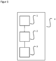
- the device according to the invention has a generator 1 which is arranged in a line section (not shown here).
- the generator 1 is driven by a turbine located in the flow-through line section and thereby generates electrical energy.
- the energy is stored in an energy store 2, which can be designed, for example, as a capacitor.
- Reference number 3 denotes a signal transmitter which emits an optical signal, for example, when fresh water is present at the tap.
- the components 1, 2 and 3 can be accommodated in a unit 4, which is for example an end or intermediate piece 4 for a water outlet.
Landscapes
- Engineering & Computer Science (AREA)
- Chemical & Material Sciences (AREA)
- Life Sciences & Earth Sciences (AREA)
- Health & Medical Sciences (AREA)
- Physics & Mathematics (AREA)
- General Physics & Mathematics (AREA)
- Mechanical Engineering (AREA)
- General Engineering & Computer Science (AREA)
- Combustion & Propulsion (AREA)
- Public Health (AREA)
- Water Supply & Treatment (AREA)
- Hydrology & Water Resources (AREA)
- Medicinal Chemistry (AREA)
- Food Science & Technology (AREA)
- Analytical Chemistry (AREA)
- Biochemistry (AREA)
- General Health & Medical Sciences (AREA)
- Immunology (AREA)
- Pathology (AREA)
- Thermal Sciences (AREA)
- Fluid Mechanics (AREA)
- Domestic Plumbing Installations (AREA)
- Physical Water Treatments (AREA)
Description
- Die Erfindung betrifft ein Verfahren zur Detektion von stagnierendem Trinkwasser gemäß dem Oberbegriff des Patentanspruchs 1 und eine Vorrichtung zur Detektion von stagnierendem Trinkwasser gemäß dem Oberbegriff des Patentanspruchs 8, siehe z.B.
DE102008039272A1 undDE102014104393A1 . - Unter stagnierendem Wasser wird Wasser verstanden, das während eines bestimmten Zeitraums in einem Leitungsabschnitt steht. Stagnierendes Wasser tritt dann auf, wenn Wasser über einen bestimmten Zeitraum hinweg nicht entnommen (abgezapft) wird.
- Bereits nach einigen Stunden kann es in stagnierendem Wasser aufgrund chemischer, physikalischer und mikrobieller Prozesse auf der Innenfläche des entsprechenden Leitungsabschnitts zur Bildung eines Biofilms kommen. Keime, die sich im Biofilm vermehren, gelangen bei einer Wasserentnahme an den Verbraucher. Hierdurch kann sich für den Verbraucher ein gesundheitliches Risiko ergeben.
- Von der Verkeimung betroffen sind Leitungsabschnitte von z.B. Armaturen, Leitungen, Duschschläuchen und Hahnausläufen. Zur Vermeidung bzw. Reduzierung von Verkeimungen in Leitungsabschnitten sind aus dem Stand der Technik Ringleitungen bekannt, von denen relativ kurze Stichleitungen zu den Wasserentnahmestellen abgehen. Der Vorteil einer derartigen Konstruktion liegt darin, dass beim Abzapfen aus jeder Wasserentnahmestelle das Wasser in der Ringleitung bewegt wird, so dass die Verweildauer des Wassers in der Ringleitung gering ist und stagnierendes Wasser lediglich in den relativ kurzen Stichleitungen auftritt. Letzteres wird durch einen Spülvorgang ausgelassen, bevor das Trinkwasser (aus der Ringleitung) verwendet werden kann. Ringleitungen sind aufwendig und nicht überall realisierbar.
- Auch materialtechnisch können Vorkehrungen getroffen werden, die eine Keimbildung reduzieren. Insbesondere sind aus dem Stand der Technik Materialien bekannt, die die Gefahr der Bildung eines Biofilms reduzieren.
- Grundsätzlich kann die Gefahr der Benutzung von verkeimtem Trinkwasser dadurch reduziert werden, dass vor dem Abzapfen von zur Verwendung vorgesehenem Trinkwasser das Wasser einige Zeit laufen gelassen wird. Hierdurch wird die Leitung gespült und mögliches Stagnations-Wasser abgeführt. Je nach Länge der Wasserzuführleitung beträgt die Laufzeit des Wassers bis zu einigen Minuten.
- Das vorbeschriebene Verfahren hat sich in der Praxis bewährt. Allerdings ist ein Ableiten von unbenutztem Wasser über einen längeren Zeitraum umweltunfreundlich, und zwar insbesondere dann, wenn aus Sicherheitsgründen das Wasser länger abgeführt wird als es eigentlich erforderlich wäre.
- Auch zeigt die Praxis, dass vor der Benutzung einer Trinkwasser-Zapfstelle häufig nicht klar ist, ob es sich bei dem anstehenden Wasser um stagnierendes Wasser handelt oder nicht. Häufig sichert sich der Verbraucher dadurch ab, dass - unabhängig von dem Stagnationsgrad des Wassers - das Wasser grundsätzlich über längeren Zeitraum laufen gelassen wird, bevor es für seine eigentliche Verwendung abgezapft wird. Unnötige Wasserverschwendung ist die Folge.
- Hier greift die Erfindung ein.
- Der Erfindung liegt die Aufgabe zugrunde, stagnierendes Wasser zu detektieren bei gleichzeitiger Reduzierung von unnötigem Wasserverbrauch.
- Die Aufgabe wird durch ein Verfahren mit den Merkmalen des Anspruchs 1 gelöst.
- Die Erfindung vereint mehrere Vorteile. Ein Vorteil besteht darin, dass durch fließendes Wasser elektrische Energie erzeugt wird. Es ist also keine gesonderte Energiequelle erforderlich. Ein weiterer wesentlicher Vorteil der Erfindung besteht darin, dass aus dem Ladezustand des Energiespeichers eine Information darüber gewonnen werden kann, ob es sich um stagnierendes Wasser handelt oder nicht. Insbesondere nutzt die Erfindung einen entladenen Energiespeicher, um hieraus die Information zu gewinnen, dass es sich bei dem Wasser in dem Leitungsabschnitt um stagnierendes Wasser handelt.
- Den Energiespeicher wird man vorzugsweise so wählen, dass seine Entladungszeit kürzer ist als die Zeit, in der das Wasser subjektiv oder objektiv als Stagnationswasser betrachtet wird. Beispielsweise beträgt die Entladungszeit weniger als 12 Stunden, vorzugsweise weniger als 6 Stunden. Je nach Einsatzzweck wird Trinkwasser bereits dann als Stagnationswasser definiert, wenn Wasser auf dem Weg im jeweiligen Leitungsabschnitt länger als 4 Stunden stillsteht. Derartige Bedingungen finden sich insbesondere in medizinischen Einrichtungen wie Krankenhäusern. Vor diesem Hintergrund kann es zweckmäßig sein, dass die Entladungszeit weniger als 4 Stunden beträgt.
- Die Erfindung kann wie vorstehend angedeutet in öffentlichen Einrichtungen wie Krankenhäusern, Alten- und Pflegeheimen oder Schulen, aber auch in privaten Haushalten zum Einsatz kommen.
- Vorzugsweise wird aus der Stagnation des Trinkwassers dessen Frischegrad abgeleitet. Es ist vorzugsweise also möglich, dass einerseits sichergestellt werden kann, dass das abgezapfte Wasser frisch ist, und dass andererseits nicht unnötiges Wasser (durch unnötiges Spülen der Leitung) verschwendet wird.
- An dieser Stelle sei darauf hingewiesen, dass im Rahmen der Erfindung unter dem Frischegrad beispielsweise lediglich die Zustände "frisch" oder "nicht frisch" verstanden werden. In Weiterbildung der Erfindung können aber auch abgestufte Frischegrade ermittelt werden. Diese werden vorzugsweise aus einem teilweise entladenen Energiespeicher abgeleitet. Wenn also der Energiespeicher eine Restladung aufweist, kann hieraus abgeleitet werden, dass das abgezapfte Wasser "noch frisch" ist.
- Vorteilhafterweise wird der Frischegrad des Wassers akustisch und/oder visuell angegeben. Der Frischegrad ist also für den Benutzer schnell erfassbar. Beispielsweise kann "frisches" Wasser mit einem Licht angezeigt werden, das z.B. grün oder blau ist. Zusätzlich oder alternativ kann ein Signalton oder eine Reihe von Signaltönen erfolgen. Bei "nicht frischem", also stagnierendem Wasser erfolgt vorzugsweise keine akustische und/oder visuelle Anzeige.
- Alternativ und ebenfalls als vorteilhaft angesehen wird es, wenn Stagnationswasser visualisiert wird. Beispielsweise kann es sich um ein rotes Signal handeln. Das Wasser wird also dadurch als "frisch" angegeben, dass kein Signal erfolgt. Bei dieser Variante handelt es sich bei dem Signal also um ein Warnsignal für Stagnationswasser.
- Sobald das Wasser über einen bestimmten, vorzugsweise einen vorgegebenen, Zeitraum in dem Leitungsabschnitt still steht, entlädt sich der Energiespeicher. Wird die Leitung bzw. der Leitungsabschnitt daraufhin gespült, lädt sich der Energiespeicher wieder auf. Vorteilhafterweise wird das Trinkwasser bei entladenem Energiespeicher nach einer bestimmten, vorzugsweise vorgegebenen, Auslaufzeit als "frisch" angegeben. In diesem Zusammenhang sind mehrere Szenarien denkbar. Beispielsweise wird das Wasser dann als "frisch" angegeben, wenn der Energiespeicher voll aufgeladen ist oder einen vorgegebenen Ladezustand erreicht hat. Auch möglich ist die Vorgabe einer konkreten Auslaufzeit, beispielsweise 1 Minute.
- Als bevorzugt wird es angesehen, wenn die Auslaufzeit einstellbar ist. Hierdurch ist das Verfahren an seinen konkreten Einsatzort anpassbar. Sofern es beispielsweise bekannt ist, dass der Leitungsabschnitt zu der Wasserentnahmestelle lang ist, wird man die Auslaufzeit eher lang wählen. Bei einem kurzen Leitungsabschnitt, beispielsweise einer kurzen Stichleitung, kann die Auslaufzeit relativ kurz gehalten werden. Durch die Einstellbarkeit kann die Menge an Spülwasser, also an auslaufendem Stagnationswasser, möglichst gering gehalten werden. Eine derartige Wassereinsparung ist umweltfreundlich.
- In der Praxis kann vorgesehen sein, dass die Auslaufzeit stufenlos einstellbar ist. Alternativ ist die Auslaufzeit in vorgegebenen Intervallen einstellbar.
- Die vorbeschriebene Einstellbarkeit bietet eine einfache Möglichkeit, das erfindungsgemäße Verfahren an Umgebungsbedingungen anzupassen. Dabei wird eine gewisse Ortskenntnis vorausgesetzt. Eine genauere Einstellbarkeit kann dadurch geschaffen werden, dass zur Bestimmung der Auslaufzeit einmalig Wasser auslaufen gelassen wird, dass die Wassertemperatur während des Auslaufens gemessen wird und dass die Auslaufzeit auf Grundlage der Wassertemperaturänderung festgelegt wird. Der Hintergrund dieser Einstellmöglichkeit liegt darin, dass sich die Wassertemperatur bei Stillstand an die Umgebungstemperatur anpasst. Hierbei handelt es sich beispielsweise um die Raumtemperatur, durch die die jeweilige Leitung geht. In nord- und westeuropäischen Ländern ist die Raumtemperatur höher als die Temperatur des aus der zentralen Wasserversorgung stammenden "frischen" Wassers. Andererseits sind auch Länder in warmen Regionen bekannt, in denen aufgrund er Klimatisierung die Raumtemperatur geringer sein kann. Sobald eine bestimmte Temperaturänderung stattfindet, kann davon ausgegangen werden, dass Frischwasser an der Entnahmestelle ansteht. In der Praxis kann die Temperaturmessing beispielsweise manuell, also durch Fühlen der Temperatur, erfolgen. Sobald sich die gefühlte Wassertemperatur subjektiv ändert, ist hierdurch das Zeitintervall festgelegt, nach dem das Wasser "frisch" ist. Die so ermittelte Auslaufzeit kann für zukünftige Wasser-Entnahmevorgänge verwendet werden.
- Als Energiespeicher kommen solche Speicher in Betracht, die elektrische Energie speichern und sich in einem geeigneten Zeitraum entladen. Beispielsweise kann ein Akkumulator zum Einsatz kommen. Da die Entladezeiten bei Akkumulatoren konstruktionsbedingt lang sind, können zusätzliche elektrische Bauteile (wie zum Beispiel eine optische Anzeige) vorgesehen sein, die vom Akkumulator gespeist werden. Hierdurch verkürzt sich die Entladezeit.
- Als besonders vorteilhaft wird es angesehen, wenn der Energiespeicher als Kondensator ausgebildet ist. Derartige Kondensatoren können konstruktiv sehr klein gehalten werden. Darüber hinaus weisen Kondensatoren geeignete Lade- und Entladekurven auf.
- Die Aufgabe wird ferner durch eine Vorrichtung mit den Merkmalen des Anspruchs 8 gelöst.
- Der Generator wird vorzugsweise durch eine Turbine angetrieben. Die Turbine ist vorteilhaft Bestandteil der Vorrichtung. Sie ist zweckmäßig im Leitungsabschnitt angeordnet.
- Die Steuer- und Auswerteinheit erfasst den Ladezustand des Energiespeichers. Der Signalgeber gibt in Abhängigkeit vom Ladezustand des Energiespeichers ein Signal ab. Wenn der Energiespeicher leer ist, gibt der Signalgeber kein Signal ab. Wenn der Energiespeicher voll ist, gibt der Signalgeber vorzugsweise ein Signal ab, insbesondere ein solches, dass das Wasser als "frisch" ausweist.
- Vorteilhafterweise handelt es sich bei dem Signal um ein optisches Signal. Das Signal kann als permanentes oder blinkendes Lichtsignal ausgebildet sein. Beispielsweise ist es denkbar, dass "frisches" Wasser durch ein erstes, beispielsweise permanentes, Lichtsignal angezeigt wird. Je nach Entladezeit des Energiespeichers wird stagnierendes Wasser mit einem zweitem, beispielsweise andersfarbigem, Lichtsignal angezeigt. Wie bereits vorstehend erläutert, erfolgt bei entladenem Energiespeicher kein Signal, wobei zusätzlich vorteilhaft vorgesehen sein kann, dass während der Aufladung des Energiespeichers, während also noch stagnierendes Wasser abläuft, ein entsprechendes Signal abgegeben wird, das anders ein kann als das erste Signal, das für "frisches" Wasser steht.
- Ebenfalls als vorteilhaft wird es angesehen, wenn nicht "frisches" Wasser signalisiert wird, sondern Stagnationswasser. Im Normalbetrieb, wenn also "frisches" Wasser an der Entnahmestelle anliegt, erfolgt vorteilhaft kein Signal. Wenn jedoch der Energiespeicher leer ist und stagnierendes Wasser entnommen wird, wird die elektrische Energie des Generators dazu genutzt, ein Signal auszugeben, dass es sich um Stagnationswasser handelt. Beispielsweise ist das Signal rot.
- Die erfindungsgemäße Vorrichtung ist einfach und aus wenigen Teilen aufgebaut. Als besonders vorteilhaft wird es angesehen, wenn die Vorrichtung als End- oder Zwischenstück für einen Wasserauslauf, insbesondere für eine Wasserarmatur, ausgebildet ist. Die erfindungsgemäße Vorrichtung kann also auch als Nachrüstteil eingebaut werden. Ein weitergehender Umbau einer Standardarmatur ist hierzu nicht erforderlich. In diesem Zusammenhang vorteilhaft es auch, wenn der Energiespeicher als Kondensator ausgebildet ist, der eine besonders kleine Baugröße der erfindungsgemäßen Vorrichtung und eine Unterbringung in dem End- oder Zwischenstück gestattet.
- In Weiterbildung der Erfindung wird vorgeschlagen, dass eine Eingabeeinrichtung vorgesehen ist, mittels der die Steuer- und Auswerteeinheit mit einem Zeitintervall gespeist werden kann. Bei dem Zeitintervall kann es sich um diejenige Zeit handeln, die das stagnierende Wasser benötigt, aus einem Leitungsabschnitt auszulaufen, bis es frisch ist. Bei entladenem Energiespeicher wird das Wasser - nach entsprechender Eingabe in die Steuer- und Auswerteinheit - erst nach dem Zeitintervall als "frisch" indiziert. Wie bereits zuvor erläutert, kann die Information über "frisches" Wasser durch ein aktives (z.B. optisches oder akustisches) Signal oder dadurch zur Verfügung gestellt werden, dass kein Signal abgegeben wird. In letzterem Fall liegt dann ein Signal an, wenn es sich um Stagnationswasser handelt.
- Zusätzlich kann ein Temperaturfühler vorgesehen sein, der eine zusätzliche Überwachung des Wassers zur Verfügung stellt. Beispielsweise kann das auslaufende Stagnationswasser dahingehend überwacht werden, ob es - ggf. nach einem voreingestellten Zeitintervall - nach einer Temperaturänderung zu einer konstanten Wassertemperatur kommt.
- Im Folgenden wird die Erfindung anhand der anhängenden Zeichnung im Zusammenhang mit dem dargestellten Ausführungsbeispiel näher erläutert. Die Zeichnung zeigt in
- Figur 1:
- in schematischer Darstellung den grundsätzlichen Aufbau einer erfindungsgemäßen Detektionsvorrichtung.
- Die erfindungsgemäße Vorrichtung weist einen Generator 1 auf, der in einem (hier nicht dargestellten) Leitungsabschnitt angeordnet ist. Der Generator 1 wird über eine im durchströmten Leitungsabschnitt befindliche Turbine angetrieben und erzeugt hierdurch elektrische Energie. Die Energie wird in einem Energiespeicher 2 gespeichert, der beispielsweise als Kondensator ausgebildet sein kann. Mit dem Bezugszeichen 3 ist ein Signalgeber gekennzeichnet, der ein zum Beispiel optisches Signal abgibt, wenn an der Zapfstelle frisches Wasser anliegt. Die Bauteile 1, 2 und 3 können in einer Einheit 4 untergebracht sein, die beispielsweise ein End- oder Zwischenstück 4 für einen Wasserauslauf ist.
Claims (13)
- Verfahren zur Detektion von stagnierendem Trinkwasser,- wobei in einem Leitungsabschnitt durch fließendes Wasser elektrische Energie erzeugt wird,dadurch gekennzeichnet,- dass die elektrische Energie in einem Energiespeicher gespeichert wird,- dass der Ladezustand des Energiespeichers erfasst wird, und- dass aus dem Ladezustand des Energiespeichers Informationen über eine mögliche Stagnation des Trinkwassers gewonnen werden.
- Verfahren nach Anspruch 1, dadurch gekennzeichnet, dass aus der Stagnation des Trinkwassers der Frischegrad abgeleitet wird.
- Verfahren nach Anspruch 2, dadurch gekennzeichnet, dass der Frischegrad des Wassers vorzugsweise akustisch und/oder visuell angegeben wird.
- Verfahren nach Anspruch 2 oder 3, dadurch gekennzeichnet, dass bei entladenem Energiespeicher das Trinkwasser nach einer vorgegebenen Auslaufzeit als "frisch" angegeben wird.
- Verfahren nach Anspruch 4, dadurch gekennzeichnet, dass die Auslaufzeit einstellbar ist.
- Verfahren nach Anspruch 4 oder 5, dadurch gekennzeichnet, dass zur Bestimmung der Auslaufzeit einmalig Wasser auslaufen gelassen wird, dass die Wassertemperatur während des Auslaufens gemessen wird und dass die Auslaufzeit auf Grundlage der Wassertemperaturänderung festgelegt wird.
- Verfahren nach einem der Ansprüche 1 bis 6, dadurch gekennzeichnet, dass der Energiespeicher als Kondensator ausgebildet ist.
- Vorrichtung zur Detektion von stagnierendem Trinkwasser, mit- einem Generator (1) zur Erzeugung elektrischer Energie, gekennzeichnet durch- einen Energiespeicher (2) zum Speichern der elektrischen Energie,- eine Steuer- und Auswerteeinheit, die den Ladezustand des Energiespeichers erfasst, und- einen Signalgeber (3), der in Abhängigkeit vom Ladezustand des Energiespeichers ein Signal abgibt.
- Vorrichtung nach Anspruch 8, dadurch gekennzeichnet, dass es sich bei dem Signal um ein optisches Signal handelt.
- Vorrichtung nach Anspruch 8 oder 9, dadurch
gekennzeichnet, dass sie als End- oder Zwischenstück (4) für einen Wasserauslauf, insbesondere eine Wasserarmatur, ausgebildet ist. - Vorrichtung nach einem der Ansprüche 8 bis 10, dadurch gekennzeichnet, dass der Energiespeicher (2) als Kondensator ausgebildet ist.
- Vorrichtung nach einem der Ansprüche 8 bis 11,
gekennzeichnet durch eine Eingabeeinrichtung, mittels der die Steuer- und Auswerteeinheit mit einem Zeitintervall gespeist werden kann. - Vorrichtung nach einem der Ansprüche 8 bis 12,
gekennzeichnet durch einen zusätzlichen Temperaturfühler.
Applications Claiming Priority (1)
| Application Number | Priority Date | Filing Date | Title |
|---|---|---|---|
| DE102015100457.7A DE102015100457A1 (de) | 2015-01-14 | 2015-01-14 | Verfahren und Vorrichtung zur Detektion von stagnierendem Wasser |
Publications (2)
| Publication Number | Publication Date |
|---|---|
| EP3045595A1 EP3045595A1 (de) | 2016-07-20 |
| EP3045595B1 true EP3045595B1 (de) | 2020-04-01 |
Family
ID=55070730
Family Applications (1)
| Application Number | Title | Priority Date | Filing Date |
|---|---|---|---|
| EP15201505.3A Active EP3045595B1 (de) | 2015-01-14 | 2015-12-21 | Verfahren und vorrichtung zur detektion von stagnierendem wasser |
Country Status (3)
| Country | Link |
|---|---|
| US (2) | US10184814B2 (de) |
| EP (1) | EP3045595B1 (de) |
| DE (1) | DE102015100457A1 (de) |
Families Citing this family (2)
| Publication number | Priority date | Publication date | Assignee | Title |
|---|---|---|---|---|
| CN106290774A (zh) * | 2016-11-17 | 2017-01-04 | 百奥森(江苏)食品安全科技有限公司 | 一种自来水终端水质检测装置 |
| US11984768B2 (en) | 2020-04-17 | 2024-05-14 | Zurn Water, Llc | Hydroelectric generator for faucet and flush valve |
Family Cites Families (12)
| Publication number | Priority date | Publication date | Assignee | Title |
|---|---|---|---|---|
| JPH0733561Y2 (ja) * | 1989-11-17 | 1995-07-31 | 株式会社イナックス | 蓄電池の充電切れ防止装置 |
| DE4410993A1 (de) * | 1994-03-30 | 1995-10-05 | Keramag Keramische Werke Ag | Berührungslose, elektronische Steuerung von Wasserausläufen |
| DE102005060890A1 (de) * | 2004-12-21 | 2006-07-20 | T.E.M.! Techn. Entwicklungen Und Management Gmbh | Spülsystem zum Zwecke der automatischen Spülung von Urinalen und ähnlichen sanitärtechnischen Einrichtungen |
| BRPI0616890A2 (pt) | 2005-10-06 | 2011-07-05 | Pionetics Corp | aparelho de tratamento de fluido, e, métodos de tratamento de um fluido, de filtração de fluido em uma célula eletroquìmica, e de operação de uma célula eletroquìmica |
| US9146564B2 (en) | 2006-03-06 | 2015-09-29 | Deka Products Limited Partnership | Product dispensing system |
| DE102007009007B4 (de) * | 2007-02-23 | 2010-10-21 | Frank Jobst | Vorrichtung zur Überwachung der Spülaktivitäten einer Wasserleitung |
| US10562757B2 (en) | 2007-09-06 | 2020-02-18 | Deka Products Limited Partnership | Product dispensing system |
| DE102008039272B4 (de) * | 2008-08-23 | 2021-08-26 | Amphiro Ag | Verfahren zur Ermittlung des Ressourcenverbrauches |
| US20140312253A1 (en) * | 2011-12-05 | 2014-10-23 | Livne Gan | Compact self powered and automated attachment to a fluid system |
| DE102013001584A1 (de) * | 2013-01-30 | 2014-07-31 | Franke Aquarotter GmbH | Sanitäranordnung |
| DE102014104395A1 (de) * | 2013-04-05 | 2014-10-09 | Herbert Wimberger | Sanitärarmatur |
| DK2886727T3 (en) * | 2013-12-17 | 2018-08-13 | Grohe Ag | SANITARY ASSEMBLY AND METHOD FOR SUPPLYING ENERGY FOR SUCH ASSEMBLY |
-
2015
- 2015-01-14 DE DE102015100457.7A patent/DE102015100457A1/de not_active Withdrawn
- 2015-12-21 EP EP15201505.3A patent/EP3045595B1/de active Active
- 2015-12-22 US US14/978,600 patent/US10184814B2/en active Active
-
2017
- 2017-10-31 US US15/798,847 patent/US10309809B2/en not_active Expired - Fee Related
Non-Patent Citations (1)
| Title |
|---|
| None * |
Also Published As
| Publication number | Publication date |
|---|---|
| US10309809B2 (en) | 2019-06-04 |
| US10184814B2 (en) | 2019-01-22 |
| US20180052021A1 (en) | 2018-02-22 |
| US20190170548A9 (en) | 2019-06-06 |
| EP3045595A1 (de) | 2016-07-20 |
| DE102015100457A1 (de) | 2016-07-14 |
| US20160202094A1 (en) | 2016-07-14 |
Similar Documents
| Publication | Publication Date | Title |
|---|---|---|
| EP0009263B1 (de) | Verfahren zur Überprüfung auf Leckverluste sowie dabei verwendbarer Messchacht | |
| EP0855473B1 (de) | Vorrichtung und Verfahren zur Nutzung von Grauwasser | |
| EP3918296B1 (de) | Verfahren zum detektieren einer leckage in einem leitungssystem und steuersystem zur durchführung des verfahrens | |
| WO2014029699A1 (de) | Leckageschutz-anordnung | |
| DE102018009511A1 (de) | Spülvorrichtung, System und Verfahren zur Durchführung von Hygienespülungen | |
| EP3045595B1 (de) | Verfahren und vorrichtung zur detektion von stagnierendem wasser | |
| EP3835495B1 (de) | Spülvorrichtung, system und verfahren zur durchführung von hygienespülungen | |
| DE102019201263A1 (de) | Trink- und Brauchwassersystem und Verfahren zum Spülen desselben | |
| DE202014105702U1 (de) | Sanitäranordnung | |
| AT519689B1 (de) | Spülvorrichtung zum spülen einer wasserleitung | |
| DE202015100139U1 (de) | Vorrichtung zur Detektion von stagnierendem Wasser | |
| DE102017105083B4 (de) | Sanitärarmatur mit einem Wasserauslass und einem Seifenauslass | |
| EP3612279A1 (de) | Feuerlöschanlage, feuerlöschsystem mit selbiger, sowie verfahren zum bestimmen der ausbreitung eines feuers | |
| CH709814A2 (de) | Einrichtung und Verfahren zum Überwachen des hygienischen Status einer Trinkwasser-Installation. | |
| DE102010008511A1 (de) | Flüssigkeitsmengenmessgerät und Verfahren zum Bestimmen einer volumetrischen Messgröße | |
| EP1517213B1 (de) | Dosiergerät zur Herstellung einer Desinfektionsmittelbrauchslösung aus Konzentraten | |
| DE102018118910A1 (de) | Spülmodul und Verfahren zum Spülen von Flüssigkeitsleitungen | |
| EP2885467A1 (de) | Leckageschutz-anordnung | |
| EP3564664A1 (de) | Wasserarmatur mit spülautomatik | |
| EP3604698B1 (de) | Verfahren und spülsystem zum spülen von wasserleitungsnetzen | |
| DE102011100347A1 (de) | Frühwarnsystem bei Rohrverstopfung | |
| DE102024122728A1 (de) | System zum Verringern der zu entsorgenden Abwassermenge | |
| DE24574C (de) | Selbstthätige Schmiervorrichtung für Dampfmaschinen | |
| DE102023110242A1 (de) | System zur Begrenzug eines kumulierten Fluiddurchflussvolumens durch einen Fluidleitungsquerschnitt und Verfahren zum Betrieb des Systems | |
| DE102017126399A1 (de) | Verfahren und Vorrichtung zum Betrieb einer Sanitäreinrichtung |
Legal Events
| Date | Code | Title | Description |
|---|---|---|---|
| PUAI | Public reference made under article 153(3) epc to a published international application that has entered the european phase |
Free format text: ORIGINAL CODE: 0009012 |
|
| AK | Designated contracting states |
Kind code of ref document: A1 Designated state(s): AL AT BE BG CH CY CZ DE DK EE ES FI FR GB GR HR HU IE IS IT LI LT LU LV MC MK MT NL NO PL PT RO RS SE SI SK SM TR |
|
| AX | Request for extension of the european patent |
Extension state: BA ME |
|
| STAA | Information on the status of an ep patent application or granted ep patent |
Free format text: STATUS: REQUEST FOR EXAMINATION WAS MADE |
|
| 17P | Request for examination filed |
Effective date: 20161220 |
|
| RBV | Designated contracting states (corrected) |
Designated state(s): AL AT BE BG CH CY CZ DE DK EE ES FI FR GB GR HR HU IE IS IT LI LT LU LV MC MK MT NL NO PL PT RO RS SE SI SK SM TR |
|
| RIC1 | Information provided on ipc code assigned before grant |
Ipc: F24D 17/00 20060101ALI20190918BHEP Ipc: E03C 1/10 20060101AFI20190918BHEP Ipc: G01N 33/18 20060101ALI20190918BHEP |
|
| GRAP | Despatch of communication of intention to grant a patent |
Free format text: ORIGINAL CODE: EPIDOSNIGR1 |
|
| STAA | Information on the status of an ep patent application or granted ep patent |
Free format text: STATUS: GRANT OF PATENT IS INTENDED |
|
| INTG | Intention to grant announced |
Effective date: 20191120 |
|
| GRAS | Grant fee paid |
Free format text: ORIGINAL CODE: EPIDOSNIGR3 |
|
| GRAA | (expected) grant |
Free format text: ORIGINAL CODE: 0009210 |
|
| STAA | Information on the status of an ep patent application or granted ep patent |
Free format text: STATUS: THE PATENT HAS BEEN GRANTED |
|
| AK | Designated contracting states |
Kind code of ref document: B1 Designated state(s): AL AT BE BG CH CY CZ DE DK EE ES FI FR GB GR HR HU IE IS IT LI LT LU LV MC MK MT NL NO PL PT RO RS SE SI SK SM TR |
|
| REG | Reference to a national code |
Ref country code: GB Ref legal event code: FG4D Free format text: NOT ENGLISH |
|
| REG | Reference to a national code |
Ref country code: AT Ref legal event code: REF Ref document number: 1251486 Country of ref document: AT Kind code of ref document: T Effective date: 20200415 Ref country code: CH Ref legal event code: EP |
|
| REG | Reference to a national code |
Ref country code: DE Ref legal event code: R096 Ref document number: 502015012140 Country of ref document: DE |
|
| REG | Reference to a national code |
Ref country code: IE Ref legal event code: FG4D Free format text: LANGUAGE OF EP DOCUMENT: GERMAN |
|
| REG | Reference to a national code |
Ref country code: CH Ref legal event code: NV Representative=s name: VALIPAT S.A. C/O BOVARD SA NEUCHATEL, CH |
|
| PG25 | Lapsed in a contracting state [announced via postgrant information from national office to epo] |
Ref country code: BG Free format text: LAPSE BECAUSE OF FAILURE TO SUBMIT A TRANSLATION OF THE DESCRIPTION OR TO PAY THE FEE WITHIN THE PRESCRIBED TIME-LIMIT Effective date: 20200701 |
|
| REG | Reference to a national code |
Ref country code: NL Ref legal event code: MP Effective date: 20200401 |
|
| REG | Reference to a national code |
Ref country code: LT Ref legal event code: MG4D |
|
| PG25 | Lapsed in a contracting state [announced via postgrant information from national office to epo] |
Ref country code: PT Free format text: LAPSE BECAUSE OF FAILURE TO SUBMIT A TRANSLATION OF THE DESCRIPTION OR TO PAY THE FEE WITHIN THE PRESCRIBED TIME-LIMIT Effective date: 20200817 Ref country code: GR Free format text: LAPSE BECAUSE OF FAILURE TO SUBMIT A TRANSLATION OF THE DESCRIPTION OR TO PAY THE FEE WITHIN THE PRESCRIBED TIME-LIMIT Effective date: 20200702 Ref country code: FI Free format text: LAPSE BECAUSE OF FAILURE TO SUBMIT A TRANSLATION OF THE DESCRIPTION OR TO PAY THE FEE WITHIN THE PRESCRIBED TIME-LIMIT Effective date: 20200401 Ref country code: NO Free format text: LAPSE BECAUSE OF FAILURE TO SUBMIT A TRANSLATION OF THE DESCRIPTION OR TO PAY THE FEE WITHIN THE PRESCRIBED TIME-LIMIT Effective date: 20200701 Ref country code: LT Free format text: LAPSE BECAUSE OF FAILURE TO SUBMIT A TRANSLATION OF THE DESCRIPTION OR TO PAY THE FEE WITHIN THE PRESCRIBED TIME-LIMIT Effective date: 20200401 Ref country code: IS Free format text: LAPSE BECAUSE OF FAILURE TO SUBMIT A TRANSLATION OF THE DESCRIPTION OR TO PAY THE FEE WITHIN THE PRESCRIBED TIME-LIMIT Effective date: 20200801 Ref country code: NL Free format text: LAPSE BECAUSE OF FAILURE TO SUBMIT A TRANSLATION OF THE DESCRIPTION OR TO PAY THE FEE WITHIN THE PRESCRIBED TIME-LIMIT Effective date: 20200401 Ref country code: CZ Free format text: LAPSE BECAUSE OF FAILURE TO SUBMIT A TRANSLATION OF THE DESCRIPTION OR TO PAY THE FEE WITHIN THE PRESCRIBED TIME-LIMIT Effective date: 20200401 Ref country code: SE Free format text: LAPSE BECAUSE OF FAILURE TO SUBMIT A TRANSLATION OF THE DESCRIPTION OR TO PAY THE FEE WITHIN THE PRESCRIBED TIME-LIMIT Effective date: 20200401 |
|
| PG25 | Lapsed in a contracting state [announced via postgrant information from national office to epo] |
Ref country code: RS Free format text: LAPSE BECAUSE OF FAILURE TO SUBMIT A TRANSLATION OF THE DESCRIPTION OR TO PAY THE FEE WITHIN THE PRESCRIBED TIME-LIMIT Effective date: 20200401 Ref country code: HR Free format text: LAPSE BECAUSE OF FAILURE TO SUBMIT A TRANSLATION OF THE DESCRIPTION OR TO PAY THE FEE WITHIN THE PRESCRIBED TIME-LIMIT Effective date: 20200401 Ref country code: LV Free format text: LAPSE BECAUSE OF FAILURE TO SUBMIT A TRANSLATION OF THE DESCRIPTION OR TO PAY THE FEE WITHIN THE PRESCRIBED TIME-LIMIT Effective date: 20200401 |
|
| PG25 | Lapsed in a contracting state [announced via postgrant information from national office to epo] |
Ref country code: AL Free format text: LAPSE BECAUSE OF FAILURE TO SUBMIT A TRANSLATION OF THE DESCRIPTION OR TO PAY THE FEE WITHIN THE PRESCRIBED TIME-LIMIT Effective date: 20200401 |
|
| REG | Reference to a national code |
Ref country code: DE Ref legal event code: R097 Ref document number: 502015012140 Country of ref document: DE |
|
| PG25 | Lapsed in a contracting state [announced via postgrant information from national office to epo] |
Ref country code: SM Free format text: LAPSE BECAUSE OF FAILURE TO SUBMIT A TRANSLATION OF THE DESCRIPTION OR TO PAY THE FEE WITHIN THE PRESCRIBED TIME-LIMIT Effective date: 20200401 Ref country code: EE Free format text: LAPSE BECAUSE OF FAILURE TO SUBMIT A TRANSLATION OF THE DESCRIPTION OR TO PAY THE FEE WITHIN THE PRESCRIBED TIME-LIMIT Effective date: 20200401 Ref country code: DK Free format text: LAPSE BECAUSE OF FAILURE TO SUBMIT A TRANSLATION OF THE DESCRIPTION OR TO PAY THE FEE WITHIN THE PRESCRIBED TIME-LIMIT Effective date: 20200401 Ref country code: ES Free format text: LAPSE BECAUSE OF FAILURE TO SUBMIT A TRANSLATION OF THE DESCRIPTION OR TO PAY THE FEE WITHIN THE PRESCRIBED TIME-LIMIT Effective date: 20200401 Ref country code: RO Free format text: LAPSE BECAUSE OF FAILURE TO SUBMIT A TRANSLATION OF THE DESCRIPTION OR TO PAY THE FEE WITHIN THE PRESCRIBED TIME-LIMIT Effective date: 20200401 |
|
| PLBE | No opposition filed within time limit |
Free format text: ORIGINAL CODE: 0009261 |
|
| STAA | Information on the status of an ep patent application or granted ep patent |
Free format text: STATUS: NO OPPOSITION FILED WITHIN TIME LIMIT |
|
| PG25 | Lapsed in a contracting state [announced via postgrant information from national office to epo] |
Ref country code: SK Free format text: LAPSE BECAUSE OF FAILURE TO SUBMIT A TRANSLATION OF THE DESCRIPTION OR TO PAY THE FEE WITHIN THE PRESCRIBED TIME-LIMIT Effective date: 20200401 Ref country code: PL Free format text: LAPSE BECAUSE OF FAILURE TO SUBMIT A TRANSLATION OF THE DESCRIPTION OR TO PAY THE FEE WITHIN THE PRESCRIBED TIME-LIMIT Effective date: 20200401 |
|
| 26N | No opposition filed |
Effective date: 20210112 |
|
| PG25 | Lapsed in a contracting state [announced via postgrant information from national office to epo] |
Ref country code: SI Free format text: LAPSE BECAUSE OF FAILURE TO SUBMIT A TRANSLATION OF THE DESCRIPTION OR TO PAY THE FEE WITHIN THE PRESCRIBED TIME-LIMIT Effective date: 20200401 |
|
| GBPC | Gb: european patent ceased through non-payment of renewal fee |
Effective date: 20201221 |
|
| PG25 | Lapsed in a contracting state [announced via postgrant information from national office to epo] |
Ref country code: MC Free format text: LAPSE BECAUSE OF FAILURE TO SUBMIT A TRANSLATION OF THE DESCRIPTION OR TO PAY THE FEE WITHIN THE PRESCRIBED TIME-LIMIT Effective date: 20200401 |
|
| REG | Reference to a national code |
Ref country code: BE Ref legal event code: MM Effective date: 20201231 |
|
| PG25 | Lapsed in a contracting state [announced via postgrant information from national office to epo] |
Ref country code: LU Free format text: LAPSE BECAUSE OF NON-PAYMENT OF DUE FEES Effective date: 20201221 Ref country code: FR Free format text: LAPSE BECAUSE OF NON-PAYMENT OF DUE FEES Effective date: 20201231 Ref country code: IE Free format text: LAPSE BECAUSE OF NON-PAYMENT OF DUE FEES Effective date: 20201221 |
|
| PG25 | Lapsed in a contracting state [announced via postgrant information from national office to epo] |
Ref country code: GB Free format text: LAPSE BECAUSE OF NON-PAYMENT OF DUE FEES Effective date: 20201221 |
|
| REG | Reference to a national code |
Ref country code: AT Ref legal event code: MM01 Ref document number: 1251486 Country of ref document: AT Kind code of ref document: T Effective date: 20201221 |
|
| PGFP | Annual fee paid to national office [announced via postgrant information from national office to epo] |
Ref country code: CH Payment date: 20211221 Year of fee payment: 7 |
|
| PG25 | Lapsed in a contracting state [announced via postgrant information from national office to epo] |
Ref country code: AT Free format text: LAPSE BECAUSE OF NON-PAYMENT OF DUE FEES Effective date: 20201221 |
|
| PG25 | Lapsed in a contracting state [announced via postgrant information from national office to epo] |
Ref country code: TR Free format text: LAPSE BECAUSE OF FAILURE TO SUBMIT A TRANSLATION OF THE DESCRIPTION OR TO PAY THE FEE WITHIN THE PRESCRIBED TIME-LIMIT Effective date: 20200401 Ref country code: MT Free format text: LAPSE BECAUSE OF FAILURE TO SUBMIT A TRANSLATION OF THE DESCRIPTION OR TO PAY THE FEE WITHIN THE PRESCRIBED TIME-LIMIT Effective date: 20200401 Ref country code: CY Free format text: LAPSE BECAUSE OF FAILURE TO SUBMIT A TRANSLATION OF THE DESCRIPTION OR TO PAY THE FEE WITHIN THE PRESCRIBED TIME-LIMIT Effective date: 20200401 |
|
| PGFP | Annual fee paid to national office [announced via postgrant information from national office to epo] |
Ref country code: IT Payment date: 20211224 Year of fee payment: 7 |
|
| PG25 | Lapsed in a contracting state [announced via postgrant information from national office to epo] |
Ref country code: MK Free format text: LAPSE BECAUSE OF FAILURE TO SUBMIT A TRANSLATION OF THE DESCRIPTION OR TO PAY THE FEE WITHIN THE PRESCRIBED TIME-LIMIT Effective date: 20200401 |
|
| PG25 | Lapsed in a contracting state [announced via postgrant information from national office to epo] |
Ref country code: BE Free format text: LAPSE BECAUSE OF NON-PAYMENT OF DUE FEES Effective date: 20201231 |
|
| PGFP | Annual fee paid to national office [announced via postgrant information from national office to epo] |
Ref country code: DE Payment date: 20221231 Year of fee payment: 8 |
|
| REG | Reference to a national code |
Ref country code: CH Ref legal event code: PL |
|
| PG25 | Lapsed in a contracting state [announced via postgrant information from national office to epo] |
Ref country code: LI Free format text: LAPSE BECAUSE OF NON-PAYMENT OF DUE FEES Effective date: 20221231 Ref country code: CH Free format text: LAPSE BECAUSE OF NON-PAYMENT OF DUE FEES Effective date: 20221231 |
|
| PG25 | Lapsed in a contracting state [announced via postgrant information from national office to epo] |
Ref country code: IT Free format text: LAPSE BECAUSE OF NON-PAYMENT OF DUE FEES Effective date: 20221221 |
|
| REG | Reference to a national code |
Ref country code: DE Ref legal event code: R119 Ref document number: 502015012140 Country of ref document: DE |
|
| PG25 | Lapsed in a contracting state [announced via postgrant information from national office to epo] |
Ref country code: DE Free format text: LAPSE BECAUSE OF NON-PAYMENT OF DUE FEES Effective date: 20240702 |
|
| PG25 | Lapsed in a contracting state [announced via postgrant information from national office to epo] |
Ref country code: DE Free format text: LAPSE BECAUSE OF NON-PAYMENT OF DUE FEES Effective date: 20240702 |
|
| PG25 | Lapsed in a contracting state [announced via postgrant information from national office to epo] |
Ref country code: IS Free format text: LAPSE BECAUSE OF NON-PAYMENT OF DUE FEES Effective date: 20200801 |