EP3045372A1 - Spring-enhanched friction damper supported by a joint - Google Patents
Spring-enhanched friction damper supported by a joint Download PDFInfo
- Publication number
- EP3045372A1 EP3045372A1 EP16151889.9A EP16151889A EP3045372A1 EP 3045372 A1 EP3045372 A1 EP 3045372A1 EP 16151889 A EP16151889 A EP 16151889A EP 3045372 A1 EP3045372 A1 EP 3045372A1
- Authority
- EP
- European Patent Office
- Prior art keywords
- spring
- axle
- friction
- friction damper
- slanting
- Prior art date
- Legal status (The legal status is an assumption and is not a legal conclusion. Google has not performed a legal analysis and makes no representation as to the accuracy of the status listed.)
- Granted
Links
- 239000000725 suspension Substances 0.000 claims abstract description 3
- 230000008859 change Effects 0.000 claims description 6
- 230000007246 mechanism Effects 0.000 claims description 3
- 238000010276 construction Methods 0.000 description 8
- 238000013016 damping Methods 0.000 description 6
- 229920001971 elastomer Polymers 0.000 description 4
- 239000007789 gas Substances 0.000 description 4
- 230000004044 response Effects 0.000 description 3
- IJGRMHOSHXDMSA-UHFFFAOYSA-N Atomic nitrogen Chemical compound N#N IJGRMHOSHXDMSA-UHFFFAOYSA-N 0.000 description 2
- 230000008901 benefit Effects 0.000 description 2
- 230000015572 biosynthetic process Effects 0.000 description 2
- 238000005096 rolling process Methods 0.000 description 2
- 229910001018 Cast iron Inorganic materials 0.000 description 1
- 239000004677 Nylon Substances 0.000 description 1
- 229910000831 Steel Inorganic materials 0.000 description 1
- 230000002301 combined effect Effects 0.000 description 1
- 230000001627 detrimental effect Effects 0.000 description 1
- 230000000694 effects Effects 0.000 description 1
- 239000000806 elastomer Substances 0.000 description 1
- 239000007788 liquid Substances 0.000 description 1
- 239000000463 material Substances 0.000 description 1
- 229910052757 nitrogen Inorganic materials 0.000 description 1
- 229920001778 nylon Polymers 0.000 description 1
- 230000009467 reduction Effects 0.000 description 1
- 239000010959 steel Substances 0.000 description 1
Images

Classifications
-
- B—PERFORMING OPERATIONS; TRANSPORTING
- B61—RAILWAYS
- B61F—RAIL VEHICLE SUSPENSIONS, e.g. UNDERFRAMES, BOGIES OR ARRANGEMENTS OF WHEEL AXLES; RAIL VEHICLES FOR USE ON TRACKS OF DIFFERENT WIDTH; PREVENTING DERAILING OF RAIL VEHICLES; WHEEL GUARDS, OBSTRUCTION REMOVERS OR THE LIKE FOR RAIL VEHICLES
- B61F5/00—Constructional details of bogies; Connections between bogies and vehicle underframes; Arrangements or devices for adjusting or allowing self-adjustment of wheel axles or bogies when rounding curves
- B61F5/26—Mounting or securing axle-boxes in vehicle or bogie underframes
- B61F5/30—Axle-boxes mounted for movement under spring control in vehicle or bogie underframes
- B61F5/301—Axle-boxes mounted for movement under spring control in vehicle or bogie underframes incorporating metal springs
-
- B—PERFORMING OPERATIONS; TRANSPORTING
- B61—RAILWAYS
- B61F—RAIL VEHICLE SUSPENSIONS, e.g. UNDERFRAMES, BOGIES OR ARRANGEMENTS OF WHEEL AXLES; RAIL VEHICLES FOR USE ON TRACKS OF DIFFERENT WIDTH; PREVENTING DERAILING OF RAIL VEHICLES; WHEEL GUARDS, OBSTRUCTION REMOVERS OR THE LIKE FOR RAIL VEHICLES
- B61F5/00—Constructional details of bogies; Connections between bogies and vehicle underframes; Arrangements or devices for adjusting or allowing self-adjustment of wheel axles or bogies when rounding curves
- B61F5/26—Mounting or securing axle-boxes in vehicle or bogie underframes
- B61F5/30—Axle-boxes mounted for movement under spring control in vehicle or bogie underframes
- B61F5/32—Guides, e.g. plates, for axle-boxes
Definitions
- the present invention relates to a spring enhanced friction damper supported by a joint, in the bogies and wheelsets of railway cars and other railway rolling stock.
- railway-car bogie and wheelset solutions are intended to attach the wheelsets flexibly and permit the axles to rotate and be steered according to the rails of the track.
- the flexes and movements of the structure must be suitably controlled and damped, so that uncontrolled movements will not take place within the operating speed range of the cars.
- the movements must be in all conditions as similar as possible, while there can be no deviations or variations in the kinetic forces. Detrimental variation can be caused, for example, by the formation of ice or rime on the guide or damper surfaces, in which case the forces and coefficients of friction affecting their movements will change uncontrollably.
- bogie and wheelset solutions are known.
- One solution for guiding sets of wheels is disclosed in United States patent application US2009/0031918 .
- at least some of the bogie's springs are supported at their upper end on a convex head-cup surface.
- the solution described is stated to improve transverse and longitudinal stiffness and friction properties. In this way hunting and wheel wear are reduced. Attempts have also been made to improve controllability by means of various elastomeric dampers and supports.
- One special feature of the invention is intended to create a friction damper, the damping response of which can be better forecast than previously, irrespective of the running situation and conditions and the operation of which can, if necessary, be adjusted.
- the intention is to create a friction damper, the damping of which can be adjusted and/or altered with the aid of the adjustment of a spring.
- the invention is based on helical springs being used in the support of at least one wheelset, and a slider, in which there is at least one curved guide surface, which guide surface has at least one radius of curvature relative to the axis parallel to the longitudinal axis of the wheelset, being fitted to the side of the upper end of each helical spring, and set to be supported on the axle box of the axle.
- a friction damper is arranged, the shape of which corresponds to the shape of the guide surface for supporting the spring plate of the upper end of the spring, and at least one planar slanting friction surface, which is arranged to correspond to a similar counter surface in the frame of the bogie/car.
- At least one spring element by means of which a spring force parallel to the slanting friction surface is formed, is fitted between the slider and the fixed support surface relative to the slider.
- the friction damper there is at least one pin, which is attached to the body of the friction damper, at least one threaded counter sleeve, which is attached to the frame of the bogie/car, at least one threaded adjustment pin, which corresponds to the threaded counter sleeve, and at least one return spring, which is fitted between the pin and adjustment pin of the friction damper's body in such a way that the pins and spring are arranged parallel to the planar friction surface, in such a way that the spring permits movement parallel to the plane of the friction surface.
- an adjustment element in the frame of the bogie/car for altering the pre-tensioning of the spring.
- the return spring is a helical spring or similar spring element based on deformation.
- the return spring is a gas or liquid spring, or similar spring element based on a change in pressure.
- the pre-tensioning or spring force parallel to the slanting friction surfaces prevents the friction surfaces from sticking and at the same time ensures that the slider presses against the axle box and that continuous contact between the slider and the friction damper is preserved.
- the direction of movement and spring force of the spring can be arranged to be parallel to the slanting friction surfaces, so that the direction of their effect is the same and the combined effect can be easily controlled.
- a significant advantage of some of the embodiments of the invention is that with the aid of them the angle of tilt of the wedge can be altered. This is important, because a steep angle of the slanting friction surfaces can lead to an excessively reduced vertical load and an uncontrolled steering response. With a small wedge angle, on the other hand, there is a greater danger of the movement of the friction surfaces sticking, or an otherwise uneven movement response. This problem can be controlled with the aid of a preset spring force or a dampened spring force.
- the present invention is intended primarily for use in the bogies and wheelsets of railway cars. It can also be adapted to similar applications in other railway rolling stock.
- Figure 1 shows the support of a wheel set of a railway car, seen from the end of the axle 1.
- On the axle is a centre point 14 marked by an arrow and the longitudinal axis of the wheelset runs through this point.
- the axle 1 and the wheels 12 (2 items) form an axle set.
- the axle set and the axle boxes 2 (2 items) with their bearings 13 form correspondingly a wheelset.
- the wheel pair and the opposite sides of the suspension are symmetrical.
- In the friction damper supported by a joint in order to form support for a wheelset of a railway car there is at least one axle 1 with wheels 12, bearings 13, and axle boxes 2, as well as helical springs 3 fitted to the axle box at both sides of the axle 1 on at least both ends of the axle 1, in order to carry the railway car.
- the helical springs 3 can be supported either on support points in the car, i.e. on the frame 4 of the car, or on the frame 4 of the bogie, which in turn supports the railway car.
- the axle box 2 In the axle box 2, there are head-cup plates 5, on which the helical springs 3 fitted between the axle box 2 and the bogie's/car's frame 4 are received.
- the axle box 2 can also consist of several components, for example, a bearing housing and a saddle, which contain head-cup surfaces for the springs.
- the bearing housing then comprises only a counter surface for the bearing of the axle and vertical guide surfaces of the saddle. These pieces are supported on each other in such a way that they can move, according to the situation, relative to each other slighting in the longitudinal and transverse directions.
- the friction damper comprises a slider 6, in which there is a first guide surface 7 and a second guide surface 15 supported on the axle box 2 (in the second alternative embodiment 19, Figure 2 ), fitted moveably to the axle box 2 of the axle 1 on the side of the upper end of every helical spring 3.
- the guide surface 7 is a spherical guide surface 7 pointing away from the axle box.
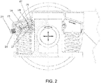
- the sliding surface of the other guide surface 15 is planar, as is the head-cup surface 18 of its axle box 2, a second alternative embodiment of the second guide surface being shown in Figure 2 .
- the first guide surface 7 is formed of at least one curved surface, which forms the guide surface 7 and which guide surface 7 has at least one radius of curvature around the axis parallel to the longitudinal axle of the wheelset.
- This guide surface can advantageously be cylindrical or spherical.
- a spherical guide surface permits a free rotation in all directions around the spherical surface, whereas a cylindrical guide surface supports the spring plate 9 against lateral torsion
- the friction damper comprises a counter surface 8 supporting the guide surface 7 of the slider 6 of the axle box 2, the shape of which corresponds to the shape of the guide surface 7 and the head-cup surface 17 of the spring plate 9, in order to support the upper end of the spring 3.
- At the upper end of the friction damper there is, on the opposite side of the head-cup surface 17 of the spring plate 9, at least one planar slanting friction surface 10, which is arranged to correspond to the similar counter surface 11 in the frame of the bogie/car 4.
- the slant of these surfaces relative to the horizontal can vary, and the surfaces or at least one of them can be surfaced, hardened, or otherwise treated in order to created suitable friction properties.
- the slider 6 is supported against the side of the axle box 2, but does not prevent the axle box 2 from moving vertically.
- the movements of the wheelset seek to rotate the axle box 2 around its vertical axis relative to the frame of the bogie/car 4, and the movements of the axle box 2 and the spring 3 correspondingly tend to move the slider 6 and the friction damper's spring plate 9 arranged against it, but if the movement surface (7 and 8) between the slider 6 and the friction damper's spring plate 9 is given a spherical shape, a change in the attitude of the slider 6 will not cause a rotational force in the spring plate 9.
- the helical spring 3 conforms well to lateral movement, and thus the helical spring 3 continues to press the slanting friction surface 10 of the friction damper evenly on the slanting counter surface 11 of the frame of the bogie/car 4, irrespective of the movements of the axle box, and the friction surface 10 and the counter-surface 11 remain precisely against each other, and a gap cannot form between them.
- the spring plate 9 remains horizontal despite the movements, whereas the head-cup plates 5 of the springs of the axle box 2 can move according to the movements of the axle box 2 caused by the steering of the wheels 12. Due to this, the slanting surfaces are continuously in a planar contact with each other.
- the friction force between the surfaces remains constant and rime, ice, or dirt cannot collect between the surfaces, which could hinder the movement of the friction surfaces and thus the travel of the bogie/car.
- the surface pressure in the movement surface 15 between the axle box 2 and the slider 6 remains even and the surfaces remain in parallel. This is made possible by the spherical or cylindrical curved surface acting as a pivot or bearing.
- the operation of the friction damper can be influenced by dimensioning.
- the radius R of the sphere or cylinder surface 7 and its head-cup surface 8 the distance between the starting point of the radius R and the sliding surface of the axle box, and the eccentricity of the starting point of the radius R and the support force acting on the spherical surface, as well as well as changes relative to the angle ⁇ relative to the vertical of the axle box 2 and the slider's movement surface 15, and the angle ⁇ of the slanting friction surface 10 and the slanting counter surface 11, can affect the surface pressures and damping.
- the surface pressure between the spherical or cylindrical curved surfaces 7 and 8 are adjusted and, with the aid of the distance between the starting point of the radius R and the sliding surface of the axle box and the eccentricity of the starting point of radius R and the support force acting on the spherical surface, the surface pressure between the curved surfaces 7 and 8 and the planar surfaces 10 and 11 can be adjusted.
- the angle ⁇ relative to the vertical of the axle box 2 and the movement surface of the slider and of the angle ⁇ relative to the horizontal of the slanting friction surface 10 and the slanting counter surface 11 the changing of the damping relative to the load can be influenced.
- damping is created on the basis of the kinetic friction between the friction surface 10 and its counter surface 11 and partly of the kinetic friction between the slider 6 and the axle box 2.
- the friction damper of Figure 1 there is, in addition, at least one core 26, which is attached to the body 22 of the friction damper, and at least one counter sleeve 24, which is attached to the frame 4 of the bogie/car. At least one adjustment pin 25, which is supported on the threaded counter sleeve 24. At least one spring element 16 is fitted between the core 26 and the adjustment pin 25, in such a way that the core 26 of the friction damper, the adjustment pin 25, and the spring 16 are arranged in parallel with the planar friction surfaces 10 and 11, in such a way that the spring 16 permits movement parallel to the friction surface 10, 11.
- the spring can be any element whatever creating a suitable spring force, such as a helical spring, a plate spring, a rubber spring, a gas spring, or a hydrospring.
- a thread is formed in the counter sleeve 24, with the aid of which the pre-tensioning of the spring can be adjusted.
- a change in pressure can be used as the adjustment element or adjustment element based on electrical positioning.
- the spring mechanism is formed on a conical adjustment pin 25 and a threaded counter sleeve 24 attached to the frame 4 of the bogie/car. The adjustment pin 25 and the core 26 of the friction damper guide the spring 16 into place, but also permit it a small degree of lateral movement.
- the friction damper is made to act over a wider angle range than without a spring.
- the angle ⁇ of the slanting friction surfaces relative to the horizontal can be 18 - 25°, or even 30°.
- a longitudinal movement can easily take place, which can be controlled with the aid of the spring.
- the surface pressure is reduced, which, together with the reduction in unnecessary movement increases the durability, service interval, and service life of the friction damper.
- the spring also prevents the jamming of the slanting friction surfaces, so that the axle remaining in a curved position when leaving a curve is prevented and the travel of the car is more stable.
- the tension of the spring is set according to the empty car, in such a way that the rebound is not too stiff, but the spring force is nevertheless sufficient to prevent jamming.
- the spring slightly increases vertical damping and lightens the wheel weight, which must be taken into account when designing the bogie and in installing and adjusting the spring.
- the spring force is set by dimensioning for the spring of the friction damper the same spring force, which is set for the base plate and locking it with a lock nut or other suitable locking element.
- the adjustment of the spring can change and it is indeed worth adjusting according to the wear in the bogie. Adjustment can be performed mechanically with the aid of pre-tensioning or by altering the gas pressure of a gas-filled spring such as a nitrogen spring.
- Figure 2 shows a second alternative embodiment of the construction of the spring element and its adjustment.
- the spring body 23 is a unified bar, on the shaft of which two flanges 27 are fitted.
- the flanges 27 are supported on the body of the spring plate 9 and in this embodiment on the counter component 29 acts as a counter surface 8 and on the frame 4 of the bogie/car.
- the spring 16 is a sleeve-like rubber spring, which is fitted between the flanges 27 around the bar of the spring body 23.
- the spring mechanism of the return spring comprises at least one spring plate 28 inside the friction damper 22 for supporting the return spring's 16 support flange 27, as well as at least one threaded counter sleeve 24 attached to the frame of the bogie/car for supporting the adjustment pin 25.
- the friction surfaces of the damper according to the invention can be made, for example, of tempered steel, with the counter surface being of fibre-reinforced nylon, reinforced rubber, or cast iron.
- the friction-surface pairs or guide-surface pairs can be made from other materials too, which have sufficient strength in the desired surface pressure and suitable friction properties.
- a construction is depicted in the example of Figure 1 , in which there is one spring 3 on each side of the axle box. In addition to these, there can be several springs in the construction, if required by the load-bearing capacity.
Landscapes
- Engineering & Computer Science (AREA)
- Mechanical Engineering (AREA)
- Vibration Prevention Devices (AREA)
- Springs (AREA)
- Vibration Dampers (AREA)
Abstract
Description
- The present invention relates to a spring enhanced friction damper supported by a joint, in the bogies and wheelsets of railway cars and other railway rolling stock.
- Railway-car bogie and wheelset solutions are intended to attach the wheelsets flexibly and permit the axles to rotate and be steered according to the rails of the track. For the steering to be controlled, the flexes and movements of the structure must be suitably controlled and damped, so that uncontrolled movements will not take place within the operating speed range of the cars. In particular, the movements must be in all conditions as similar as possible, while there can be no deviations or variations in the kinetic forces. Detrimental variation can be caused, for example, by the formation of ice or rime on the guide or damper surfaces, in which case the forces and coefficients of friction affecting their movements will change uncontrollably.
- Many different kinds of bogie and wheelset solutions are known. One solution for guiding sets of wheels is disclosed in United States patent application
US2009/0031918 . In it, at least some of the bogie's springs are supported at their upper end on a convex head-cup surface. The solution described is stated to improve transverse and longitudinal stiffness and friction properties. In this way hunting and wheel wear are reduced. Attempts have also been made to improve controllability by means of various elastomeric dampers and supports. - Though bogies and wheelsets could be made of operate well in some operating conditions, changes in the weather, such as changes in temperature and moisture, cause difficulties. Moisture can collect in structures and components, and in turn cause the formation of ice or rime. This can lead particularly to sliding surfaces jamming or their friction properties changing, as a result of which the travel of the bogie or wheelset changes. For the aforementioned reasons, it would be advantageous to create a structure, the operation of which is improved especially in changing weather conditions.
- One special feature of the invention is intended to create a friction damper, the damping response of which can be better forecast than previously, irrespective of the running situation and conditions and the operation of which can, if necessary, be adjusted. According to one embodiment of the invention, the intention is to create a friction damper, the damping of which can be adjusted and/or altered with the aid of the adjustment of a spring.
- The invention is based on helical springs being used in the support of at least one wheelset, and a slider, in which there is at least one curved guide surface, which guide surface has at least one radius of curvature relative to the axis parallel to the longitudinal axis of the wheelset, being fitted to the side of the upper end of each helical spring, and set to be supported on the axle box of the axle. At the upper end of the helical spring, a friction damper is arranged, the shape of which corresponds to the shape of the guide surface for supporting the spring plate of the upper end of the spring, and at least one planar slanting friction surface, which is arranged to correspond to a similar counter surface in the frame of the bogie/car. At least one spring element, by means of which a spring force parallel to the slanting friction surface is formed, is fitted between the slider and the fixed support surface relative to the slider.
- In the friction damper, there is at least one pin, which is attached to the body of the friction damper, at least one threaded counter sleeve, which is attached to the frame of the bogie/car, at least one threaded adjustment pin, which corresponds to the threaded counter sleeve, and at least one return spring, which is fitted between the pin and adjustment pin of the friction damper's body in such a way that the pins and spring are arranged parallel to the planar friction surface, in such a way that the spring permits movement parallel to the plane of the friction surface.
- According to one embodiment of the invention, there is an adjustment element in the frame of the bogie/car for altering the pre-tensioning of the spring.
- According to one embodiment, the return spring is a helical spring or similar spring element based on deformation.
- According to one embodiment, the return spring is a gas or liquid spring, or similar spring element based on a change in pressure.
- Several advantages are gained with the aid of the invention.
- With the aid of the invention, it is possible to ensure the operation of the friction damper in all weather conditions. The pre-tensioning or spring force parallel to the slanting friction surfaces prevents the friction surfaces from sticking and at the same time ensures that the slider presses against the axle box and that continuous contact between the slider and the friction damper is preserved. The direction of movement and spring force of the spring can be arranged to be parallel to the slanting friction surfaces, so that the direction of their effect is the same and the combined effect can be easily controlled. A significant advantage of some of the embodiments of the invention is that with the aid of them the angle of tilt of the wedge can be altered. This is important, because a steep angle of the slanting friction surfaces can lead to an excessively reduced vertical load and an uncontrolled steering response. With a small wedge angle, on the other hand, there is a greater danger of the movement of the friction surfaces sticking, or an otherwise uneven movement response. This problem can be controlled with the aid of a preset spring force or a dampened spring force.
-
-
Figure 1 shows a partial cross-section of one embodiment of the invention. -
Figure 2 shows a partial cross-section of a second alternative embodiment of the spring element and its adjustment. - The present invention is intended primarily for use in the bogies and wheelsets of railway cars. It can also be adapted to similar applications in other railway rolling stock.
-
Figure 1 shows the support of a wheel set of a railway car, seen from the end of the axle 1. On the axle is a centre point 14 marked by an arrow and the longitudinal axis of the wheelset runs through this point. The axle 1 and the wheels 12 (2 items) form an axle set. The axle set and the axle boxes 2 (2 items) with theirbearings 13 form correspondingly a wheelset. The wheel pair and the opposite sides of the suspension are symmetrical. In the friction damper supported by a joint, in order to form support for a wheelset of a railway car there is at least one axle 1 with wheels 12,bearings 13, and axle boxes 2, as well as helical springs 3 fitted to the axle box at both sides of the axle 1 on at least both ends of the axle 1, in order to carry the railway car. The helical springs 3 can be supported either on support points in the car, i.e. on the frame 4 of the car, or on the frame 4 of the bogie, which in turn supports the railway car. In the axle box 2, there are head-cup plates 5, on which the helical springs 3 fitted between the axle box 2 and the bogie's/car's frame 4 are received. - The axle box 2 can also consist of several components, for example, a bearing housing and a saddle, which contain head-cup surfaces for the springs. The bearing housing then comprises only a counter surface for the bearing of the axle and vertical guide surfaces of the saddle. These pieces are supported on each other in such a way that they can move, according to the situation, relative to each other slighting in the longitudinal and transverse directions.
- The friction damper comprises a slider 6, in which there is a first guide surface 7 and a
second guide surface 15 supported on the axle box 2 (in the second alternative embodiment 19,Figure 2 ), fitted moveably to the axle box 2 of the axle 1 on the side of the upper end of every helical spring 3. In this embodiment, the guide surface 7 is a spherical guide surface 7 pointing away from the axle box. The sliding surface of theother guide surface 15 is planar, as is the head-cup surface 18 of its axle box 2, a second alternative embodiment of the second guide surface being shown inFigure 2 . The first guide surface 7 is formed of at least one curved surface, which forms the guide surface 7 and which guide surface 7 has at least one radius of curvature around the axis parallel to the longitudinal axle of the wheelset. This guide surface can advantageously be cylindrical or spherical. A spherical guide surface permits a free rotation in all directions around the spherical surface, whereas a cylindrical guide surface supports the spring plate 9 against lateral torsion. - A spring plate 9, with the aid of which the actual friction damper is formed, is fitted to the upper end of the helical springs 3. The friction damper comprises a counter surface 8 supporting the guide surface 7 of the slider 6 of the axle box 2, the shape of which corresponds to the shape of the guide surface 7 and the head-cup surface 17 of the spring plate 9, in order to support the upper end of the spring 3. At the upper end of the friction damper, there is, on the opposite side of the head-cup surface 17 of the spring plate 9, at least one planar
slanting friction surface 10, which is arranged to correspond to thesimilar counter surface 11 in the frame of the bogie/car 4. The slant of these surfaces relative to the horizontal can vary, and the surfaces or at least one of them can be surfaced, hardened, or otherwise treated in order to created suitable friction properties. - In the friction damper according to the invention, the slider 6 is supported against the side of the axle box 2, but does not prevent the axle box 2 from moving vertically. The movements of the wheelset seek to rotate the axle box 2 around its vertical axis relative to the frame of the bogie/car 4, and the movements of the axle box 2 and the spring 3 correspondingly tend to move the slider 6 and the friction damper's spring plate 9 arranged against it, but if the movement surface (7 and 8) between the slider 6 and the friction damper's spring plate 9 is given a spherical shape, a change in the attitude of the slider 6 will not cause a rotational force in the spring plate 9. The helical spring 3 conforms well to lateral movement, and thus the helical spring 3 continues to press the
slanting friction surface 10 of the friction damper evenly on theslanting counter surface 11 of the frame of the bogie/car 4, irrespective of the movements of the axle box, and thefriction surface 10 and thecounter-surface 11 remain precisely against each other, and a gap cannot form between them. The spring plate 9 remains horizontal despite the movements, whereas the head-cup plates 5 of the springs of the axle box 2 can move according to the movements of the axle box 2 caused by the steering of the wheels 12. Due to this, the slanting surfaces are continuously in a planar contact with each other. The friction force between the surfaces remains constant and rime, ice, or dirt cannot collect between the surfaces, which could hinder the movement of the friction surfaces and thus the travel of the bogie/car. Correspondingly, the surface pressure in themovement surface 15 between the axle box 2 and the slider 6 remains even and the surfaces remain in parallel. This is made possible by the spherical or cylindrical curved surface acting as a pivot or bearing. In addition, it is advantageous to arrange the longitudinal axis of the helical spring 3 at, or close to the centre point of the friction surface, when the surface pressure will be as even as possible over the whole surface. - The operation of the friction damper can be influenced by dimensioning. For example, the radius R of the sphere or cylinder surface 7 and its head-cup surface 8, the distance between the starting point of the radius R and the sliding surface of the axle box, and the eccentricity of the starting point of the radius R and the support force acting on the spherical surface, as well as well as changes relative to the angle β relative to the vertical of the axle box 2 and the slider's
movement surface 15, and the angle α of the slantingfriction surface 10 and the slantingcounter surface 11, can affect the surface pressures and damping. By means of the dimensioning of the radius R, the surface pressure between the spherical or cylindrical curved surfaces 7 and 8 are adjusted and, with the aid of the distance between the starting point of the radius R and the sliding surface of the axle box and the eccentricity of the starting point of radius R and the support force acting on the spherical surface, the surface pressure between the curved surfaces 7 and 8 and theplanar surfaces friction surface 10 and the slantingcounter surface 11, the changing of the damping relative to the load can be influenced. In this embodiment, damping is created on the basis of the kinetic friction between thefriction surface 10 and itscounter surface 11 and partly of the kinetic friction between the slider 6 and the axle box 2. - In the friction damper of
Figure 1 , there is, in addition, at least onecore 26, which is attached to thebody 22 of the friction damper, and at least onecounter sleeve 24, which is attached to the frame 4 of the bogie/car. At least oneadjustment pin 25, which is supported on the threadedcounter sleeve 24. At least onespring element 16 is fitted between the core 26 and theadjustment pin 25, in such a way that thecore 26 of the friction damper, theadjustment pin 25, and thespring 16 are arranged in parallel with the planar friction surfaces 10 and 11, in such a way that thespring 16 permits movement parallel to thefriction surface - A thread is formed in the
counter sleeve 24, with the aid of which the pre-tensioning of the spring can be adjusted. A change in pressure can be used as the adjustment element or adjustment element based on electrical positioning. The spring mechanism is formed on aconical adjustment pin 25 and a threadedcounter sleeve 24 attached to the frame 4 of the bogie/car. Theadjustment pin 25 and thecore 26 of the friction damper guide thespring 16 into place, but also permit it a small degree of lateral movement. - With the aid of the spring, the friction damper is made to act over a wider angle range than without a spring. In the spring-enhanced friction damper, the angle α of the slanting friction surfaces relative to the horizontal can be 18 - 25°, or even 30°. At a lesser angle, a longitudinal movement can easily take place, which can be controlled with the aid of the spring. With the aid of a low angle, the surface pressure is reduced, which, together with the reduction in unnecessary movement increases the durability, service interval, and service life of the friction damper. The spring also prevents the jamming of the slanting friction surfaces, so that the axle remaining in a curved position when leaving a curve is prevented and the travel of the car is more stable. The tension of the spring is set according to the empty car, in such a way that the rebound is not too stiff, but the spring force is nevertheless sufficient to prevent jamming. The spring slightly increases vertical damping and lightens the wheel weight, which must be taken into account when designing the bogie and in installing and adjusting the spring. The spring force is set by dimensioning for the spring of the friction damper the same spring force, which is set for the base plate and locking it with a lock nut or other suitable locking element. The adjustment of the spring can change and it is indeed worth adjusting according to the wear in the bogie. Adjustment can be performed mechanically with the aid of pre-tensioning or by altering the gas pressure of a gas-filled spring such as a nitrogen spring.
-
Figure 2 shows a second alternative embodiment of the construction of the spring element and its adjustment. In this construction, the spring body 23 is a unified bar, on the shaft of which twoflanges 27 are fitted. Theflanges 27 are supported on the body of the spring plate 9 and in this embodiment on thecounter component 29 acts as a counter surface 8 and on the frame 4 of the bogie/car. In this construction, thespring 16 is a sleeve-like rubber spring, which is fitted between theflanges 27 around the bar of the spring body 23. In this construction, the spring mechanism of the return spring comprises at least onespring plate 28 inside thefriction damper 22 for supporting the return spring's 16support flange 27, as well as at least one threadedcounter sleeve 24 attached to the frame of the bogie/car for supporting theadjustment pin 25. At least one flanged guide bar 23, for supporting theadjustment pin 25 and thesupport flange 27 of thereturn spring 16 and guiding the flexing movement parallel to the longitudinal axis of thereturn spring 16. - The friction surfaces of the damper according to the invention can be made, for example, of tempered steel, with the counter surface being of fibre-reinforced nylon, reinforced rubber, or cast iron. However, it is obvious that the friction-surface pairs or guide-surface pairs can be made from other materials too, which have sufficient strength in the desired surface pressure and suitable friction properties.
- A construction is depicted in the example of
Figure 1 , in which there is one spring 3 on each side of the axle box. In addition to these, there can be several springs in the construction, if required by the load-bearing capacity. - List of reference numbers,
Figure 1 : - 1 axle
- 2 axle box
- 3 helical spring
- 4 frame (bogie/car)
- 5 head cup (axle box's 2 or saddle's head cup 5 for the helical spring 3)
- 6 slider
- 7 first guide surface (surface against the slider's 6 spring plate)
- 8 counter surface (surface against the spring plate's 9 slider 6)
- 9 spring plate
- 10 slanting friction surface (spring plate's 9 surface against the bogie's/car's frame 4)
- 11 slanting counter surface (surface against the spring plate 9 of the bogie's/car's frame 4)
- 12 wheel
- 13 bearing
- 14 centre point
- 15 second guide surface (slider's 6 surface against the axle box 2)
- 16 return spring (helical spring)
- 18 axle box's counter surface (surface of the axle box 2 against the slider 6)
- 22 body of the friction damper
- 24 threaded counter sleeve
- 25 adjustment pin
- 26 core of the friction damper
- R radius of the counter surface
- α angle relative to the horizontal plane
- β angle relative to the vertical plane
- List of reference numbers,
Figure 2 , second alternative embodiment of the spring element and its adjustment: - 16 return spring (elastomer spring, i.e. different to the construction according to
Figure 1 ) - 22 body of the friction damper
- 23 flanged guide bar
- 24 threaded counter sleeve
- 25 adjustment pin (head of the adjustment pin is different to the construction according to
Figure 1 ) - 27 support flange of the spring
- 28 spring plate (spring plate of the return spring 16)
Claims (7)
- Friction damper supported by a joint in the suspension of a wheelset of a railway car, in at least one wheelset, which comprises at least one axle (1), together with wheels (12), bearings (13), and axle boxes (2), there are helical springs (3) fitted to the ends of the axle (1) on both sides of the axle's (1) axle box (3), in order to support the railway car, or to attach the railway car to the frame (4) of the bogie,
characterized
by a slider (6) on the side of the upper end of each helical spring (3) and arranged to be moveably attached to the axle's (1) axle box (2), and in which there is at least one curved guide surface (7), which guide surface (7) has at least one radius of curvature parallel to the axis of the wheelset around the axle, and
by a friction damper (22) fitted to the upper end of the helical springs (3), which comprises a counter surface (8) supported on the curved guide surface (7) of the slider (6) of the axle box (2), the shape of which corresponds to the shape of the curved guide surface (7), a spring plate (9), which contains a head cup (17) for supporting the upper end of the helical spring (3), and at least one planar slanting friction surface (10), which is supported on a planar slanting counter surface (11) in the frame of the bogie/car (4), and which is arranged to correspond to the slanting friction surface (10) of the friction damper,
by at least one spring (16), which is arranged in parallel with the planar slanting counter surface (11) in the frame (4) of the bogie/car, and the slanting friction surface (10) of the friction damper, in such a way that it creates a spring force parallel to the plan of the slanting friction surface (10). - Damper according to Claim 1, characterized- by at least one core (26), which is supported on the friction damper (22),- by at least one threaded counter sleeve (24), which is attached to the frame (4) of the bogie/car, and- by at least one adjustment pin (25) which is supported on the threaded counter sleeve (24),- at least one spring element (16), which is fitted between the core (26) and the adjustment pin (25), and in which- the core (26) of the friction damper, the adjustment pin (25), and the spring (16) are arranged in parallel with the planar slanting friction surface (10), in such a way that the spring (16) permits movement parallel to the plane of the friction surface (10).
- Damper according to Claim 1 or 2, characterized in that its spring mechanism includes an adjustment element for altering the pre-tensioning of the spring (16).
- Friction damper according to any of Claims 1 - 3, characterized in that the adjustment element is a thread.
- Friction damper according to any of Claims 1 - 4, characterized in that the spring (16) is a helical spring or a similar spring element based on deformation.
- Friction damper according to any of Claims 1 - 5, characterized in that the spring (16) is a gas spring or a hydrospring or a similar spring element based on a change in pressure.
- Friction damper according to any of Claims 1 - 6, characterized in that the adjustment element is a pressure adjustment element.
Applications Claiming Priority (1)
| Application Number | Priority Date | Filing Date | Title |
|---|---|---|---|
| FI20155039 | 2015-01-19 |
Publications (2)
| Publication Number | Publication Date |
|---|---|
| EP3045372A1 true EP3045372A1 (en) | 2016-07-20 |
| EP3045372B1 EP3045372B1 (en) | 2020-02-26 |
Family
ID=55486434
Family Applications (1)
| Application Number | Title | Priority Date | Filing Date |
|---|---|---|---|
| EP16151889.9A Active EP3045372B1 (en) | 2015-01-19 | 2016-01-19 | Spring-enhanched friction damper supported by a joint |
Country Status (1)
| Country | Link |
|---|---|
| EP (1) | EP3045372B1 (en) |
Citations (4)
| Publication number | Priority date | Publication date | Assignee | Title |
|---|---|---|---|---|
| WO2001085521A1 (en) * | 2000-05-11 | 2001-11-15 | Daimlerchrysler Ag | Undercarriage of a rail vehicle with radially adjustable wheelsets |
| EP1186504A2 (en) * | 2000-09-11 | 2002-03-13 | Naco Incorporated | Railcar truck |
| GB2448804A (en) * | 2007-04-28 | 2008-10-29 | Sct Europ Ltd | Suspension for a rail vehicle bogie |
| US20090031918A1 (en) | 2005-01-07 | 2009-02-05 | Sct Technology, Llc | Railway Bogies |
-
2016
- 2016-01-19 EP EP16151889.9A patent/EP3045372B1/en active Active
Patent Citations (4)
| Publication number | Priority date | Publication date | Assignee | Title |
|---|---|---|---|---|
| WO2001085521A1 (en) * | 2000-05-11 | 2001-11-15 | Daimlerchrysler Ag | Undercarriage of a rail vehicle with radially adjustable wheelsets |
| EP1186504A2 (en) * | 2000-09-11 | 2002-03-13 | Naco Incorporated | Railcar truck |
| US20090031918A1 (en) | 2005-01-07 | 2009-02-05 | Sct Technology, Llc | Railway Bogies |
| GB2448804A (en) * | 2007-04-28 | 2008-10-29 | Sct Europ Ltd | Suspension for a rail vehicle bogie |
Also Published As
| Publication number | Publication date |
|---|---|
| EP3045372B1 (en) | 2020-02-26 |
Similar Documents
| Publication | Publication Date | Title |
|---|---|---|
| CA2846165C (en) | Stabilized railway freight car truck | |
| JP6633120B2 (en) | Body support device and railway vehicle | |
| US6817301B1 (en) | Railroad freight car truck suspension yaw stabilizer | |
| CA1060932A (en) | Railway truck side bearing | |
| EP2647541A1 (en) | Central suspension apparatus, goods wagon bogie and express railroad goods wagon | |
| EP3045374B1 (en) | Weighing arrangement | |
| EP3369640A1 (en) | Method for improving overall performance of rail vehicle bogie and suspension damping system | |
| US9956968B2 (en) | Bearing adapter side frame interface for a railway car truck | |
| RU2573100C1 (en) | Railway vehicle bogie | |
| US20130056919A1 (en) | Damping device | |
| RU77592U1 (en) | TWO-WAY CAR TRUCK | |
| CN107244332B (en) | Railway wagon bogie | |
| AU2010352460A1 (en) | Railway freight car bogie | |
| RU133486U1 (en) | TWO-axle RAILWAY TRUCK CAR | |
| EP3045372B1 (en) | Spring-enhanched friction damper supported by a joint | |
| EP3045373B1 (en) | Friction damper supported by a joint | |
| RU90396U1 (en) | LATERAL BRACKET OF THE BODY OF THE LOAD RAILWAY CAR | |
| EP3135553B1 (en) | Method to prevent rupture of steel spring | |
| CN107253483B (en) | Railway wagon bogie | |
| US2394548A (en) | Spring suspension for railroad cars | |
| RU2610892C1 (en) | Body lateral support at bogie | |
| RU2760372C1 (en) | Eight-axle rail road carriage | |
| US5537932A (en) | Railway truck bearing lateral thrust pads | |
| EP3848269B1 (en) | Bogie for rubber-tired light rail vehicle | |
| WO2021158134A1 (en) | Friction damper, particularly in bogie suspension system |
Legal Events
| Date | Code | Title | Description |
|---|---|---|---|
| PUAI | Public reference made under article 153(3) epc to a published international application that has entered the european phase |
Free format text: ORIGINAL CODE: 0009012 |
|
| AK | Designated contracting states |
Kind code of ref document: A1 Designated state(s): AL AT BE BG CH CY CZ DE DK EE ES FI FR GB GR HR HU IE IS IT LI LT LU LV MC MK MT NL NO PL PT RO RS SE SI SK SM TR |
|
| AX | Request for extension of the european patent |
Extension state: BA ME |
|
| STAA | Information on the status of an ep patent application or granted ep patent |
Free format text: STATUS: REQUEST FOR EXAMINATION WAS MADE |
|
| 17P | Request for examination filed |
Effective date: 20170120 |
|
| RBV | Designated contracting states (corrected) |
Designated state(s): AL AT BE BG CH CY CZ DE DK EE ES FI FR GB GR HR HU IE IS IT LI LT LU LV MC MK MT NL NO PL PT RO RS SE SI SK SM TR |
|
| GRAP | Despatch of communication of intention to grant a patent |
Free format text: ORIGINAL CODE: EPIDOSNIGR1 |
|
| STAA | Information on the status of an ep patent application or granted ep patent |
Free format text: STATUS: GRANT OF PATENT IS INTENDED |
|
| INTG | Intention to grant announced |
Effective date: 20190903 |
|
| RIN1 | Information on inventor provided before grant (corrected) |
Inventor name: JAAKOLA, EERO |
|
| GRAS | Grant fee paid |
Free format text: ORIGINAL CODE: EPIDOSNIGR3 |
|
| GRAA | (expected) grant |
Free format text: ORIGINAL CODE: 0009210 |
|
| STAA | Information on the status of an ep patent application or granted ep patent |
Free format text: STATUS: THE PATENT HAS BEEN GRANTED |
|
| AK | Designated contracting states |
Kind code of ref document: B1 Designated state(s): AL AT BE BG CH CY CZ DE DK EE ES FI FR GB GR HR HU IE IS IT LI LT LU LV MC MK MT NL NO PL PT RO RS SE SI SK SM TR |
|
| RAP1 | Party data changed (applicant data changed or rights of an application transferred) |
Owner name: VR-YHTYMAE OY |
|
| REG | Reference to a national code |
Ref country code: GB Ref legal event code: FG4D |
|
| REG | Reference to a national code |
Ref country code: CH Ref legal event code: EP |
|
| REG | Reference to a national code |
Ref country code: AT Ref legal event code: REF Ref document number: 1237276 Country of ref document: AT Kind code of ref document: T Effective date: 20200315 |
|
| REG | Reference to a national code |
Ref country code: IE Ref legal event code: FG4D |
|
| REG | Reference to a national code |
Ref country code: DE Ref legal event code: R096 Ref document number: 602016030384 Country of ref document: DE |
|
| PG25 | Lapsed in a contracting state [announced via postgrant information from national office to epo] |
Ref country code: NO Free format text: LAPSE BECAUSE OF FAILURE TO SUBMIT A TRANSLATION OF THE DESCRIPTION OR TO PAY THE FEE WITHIN THE PRESCRIBED TIME-LIMIT Effective date: 20200526 Ref country code: FI Free format text: LAPSE BECAUSE OF FAILURE TO SUBMIT A TRANSLATION OF THE DESCRIPTION OR TO PAY THE FEE WITHIN THE PRESCRIBED TIME-LIMIT Effective date: 20200226 Ref country code: RS Free format text: LAPSE BECAUSE OF FAILURE TO SUBMIT A TRANSLATION OF THE DESCRIPTION OR TO PAY THE FEE WITHIN THE PRESCRIBED TIME-LIMIT Effective date: 20200226 |
|
| REG | Reference to a national code |
Ref country code: NL Ref legal event code: MP Effective date: 20200226 |
|
| REG | Reference to a national code |
Ref country code: LT Ref legal event code: MG4D |
|
| PG25 | Lapsed in a contracting state [announced via postgrant information from national office to epo] |
Ref country code: BG Free format text: LAPSE BECAUSE OF FAILURE TO SUBMIT A TRANSLATION OF THE DESCRIPTION OR TO PAY THE FEE WITHIN THE PRESCRIBED TIME-LIMIT Effective date: 20200526 Ref country code: SE Free format text: LAPSE BECAUSE OF FAILURE TO SUBMIT A TRANSLATION OF THE DESCRIPTION OR TO PAY THE FEE WITHIN THE PRESCRIBED TIME-LIMIT Effective date: 20200226 Ref country code: IS Free format text: LAPSE BECAUSE OF FAILURE TO SUBMIT A TRANSLATION OF THE DESCRIPTION OR TO PAY THE FEE WITHIN THE PRESCRIBED TIME-LIMIT Effective date: 20200626 Ref country code: LV Free format text: LAPSE BECAUSE OF FAILURE TO SUBMIT A TRANSLATION OF THE DESCRIPTION OR TO PAY THE FEE WITHIN THE PRESCRIBED TIME-LIMIT Effective date: 20200226 Ref country code: GR Free format text: LAPSE BECAUSE OF FAILURE TO SUBMIT A TRANSLATION OF THE DESCRIPTION OR TO PAY THE FEE WITHIN THE PRESCRIBED TIME-LIMIT Effective date: 20200527 Ref country code: HR Free format text: LAPSE BECAUSE OF FAILURE TO SUBMIT A TRANSLATION OF THE DESCRIPTION OR TO PAY THE FEE WITHIN THE PRESCRIBED TIME-LIMIT Effective date: 20200226 |
|
| PG25 | Lapsed in a contracting state [announced via postgrant information from national office to epo] |
Ref country code: NL Free format text: LAPSE BECAUSE OF FAILURE TO SUBMIT A TRANSLATION OF THE DESCRIPTION OR TO PAY THE FEE WITHIN THE PRESCRIBED TIME-LIMIT Effective date: 20200226 |
|
| PG25 | Lapsed in a contracting state [announced via postgrant information from national office to epo] |
Ref country code: SM Free format text: LAPSE BECAUSE OF FAILURE TO SUBMIT A TRANSLATION OF THE DESCRIPTION OR TO PAY THE FEE WITHIN THE PRESCRIBED TIME-LIMIT Effective date: 20200226 Ref country code: EE Free format text: LAPSE BECAUSE OF FAILURE TO SUBMIT A TRANSLATION OF THE DESCRIPTION OR TO PAY THE FEE WITHIN THE PRESCRIBED TIME-LIMIT Effective date: 20200226 Ref country code: DK Free format text: LAPSE BECAUSE OF FAILURE TO SUBMIT A TRANSLATION OF THE DESCRIPTION OR TO PAY THE FEE WITHIN THE PRESCRIBED TIME-LIMIT Effective date: 20200226 Ref country code: PT Free format text: LAPSE BECAUSE OF FAILURE TO SUBMIT A TRANSLATION OF THE DESCRIPTION OR TO PAY THE FEE WITHIN THE PRESCRIBED TIME-LIMIT Effective date: 20200719 Ref country code: ES Free format text: LAPSE BECAUSE OF FAILURE TO SUBMIT A TRANSLATION OF THE DESCRIPTION OR TO PAY THE FEE WITHIN THE PRESCRIBED TIME-LIMIT Effective date: 20200226 Ref country code: LT Free format text: LAPSE BECAUSE OF FAILURE TO SUBMIT A TRANSLATION OF THE DESCRIPTION OR TO PAY THE FEE WITHIN THE PRESCRIBED TIME-LIMIT Effective date: 20200226 Ref country code: RO Free format text: LAPSE BECAUSE OF FAILURE TO SUBMIT A TRANSLATION OF THE DESCRIPTION OR TO PAY THE FEE WITHIN THE PRESCRIBED TIME-LIMIT Effective date: 20200226 Ref country code: CZ Free format text: LAPSE BECAUSE OF FAILURE TO SUBMIT A TRANSLATION OF THE DESCRIPTION OR TO PAY THE FEE WITHIN THE PRESCRIBED TIME-LIMIT Effective date: 20200226 Ref country code: SK Free format text: LAPSE BECAUSE OF FAILURE TO SUBMIT A TRANSLATION OF THE DESCRIPTION OR TO PAY THE FEE WITHIN THE PRESCRIBED TIME-LIMIT Effective date: 20200226 |
|
| REG | Reference to a national code |
Ref country code: AT Ref legal event code: MK05 Ref document number: 1237276 Country of ref document: AT Kind code of ref document: T Effective date: 20200226 |
|
| REG | Reference to a national code |
Ref country code: DE Ref legal event code: R097 Ref document number: 602016030384 Country of ref document: DE |
|
| PLBE | No opposition filed within time limit |
Free format text: ORIGINAL CODE: 0009261 |
|
| STAA | Information on the status of an ep patent application or granted ep patent |
Free format text: STATUS: NO OPPOSITION FILED WITHIN TIME LIMIT |
|
| PG25 | Lapsed in a contracting state [announced via postgrant information from national office to epo] |
Ref country code: IT Free format text: LAPSE BECAUSE OF FAILURE TO SUBMIT A TRANSLATION OF THE DESCRIPTION OR TO PAY THE FEE WITHIN THE PRESCRIBED TIME-LIMIT Effective date: 20200226 Ref country code: AT Free format text: LAPSE BECAUSE OF FAILURE TO SUBMIT A TRANSLATION OF THE DESCRIPTION OR TO PAY THE FEE WITHIN THE PRESCRIBED TIME-LIMIT Effective date: 20200226 |
|
| 26N | No opposition filed |
Effective date: 20201127 |
|
| PG25 | Lapsed in a contracting state [announced via postgrant information from national office to epo] |
Ref country code: PL Free format text: LAPSE BECAUSE OF FAILURE TO SUBMIT A TRANSLATION OF THE DESCRIPTION OR TO PAY THE FEE WITHIN THE PRESCRIBED TIME-LIMIT Effective date: 20200226 Ref country code: SI Free format text: LAPSE BECAUSE OF FAILURE TO SUBMIT A TRANSLATION OF THE DESCRIPTION OR TO PAY THE FEE WITHIN THE PRESCRIBED TIME-LIMIT Effective date: 20200226 |
|
| REG | Reference to a national code |
Ref country code: DE Ref legal event code: R119 Ref document number: 602016030384 Country of ref document: DE |
|
| PG25 | Lapsed in a contracting state [announced via postgrant information from national office to epo] |
Ref country code: MC Free format text: LAPSE BECAUSE OF FAILURE TO SUBMIT A TRANSLATION OF THE DESCRIPTION OR TO PAY THE FEE WITHIN THE PRESCRIBED TIME-LIMIT Effective date: 20200226 |
|
| REG | Reference to a national code |
Ref country code: CH Ref legal event code: PL |
|
| GBPC | Gb: european patent ceased through non-payment of renewal fee |
Effective date: 20210119 |
|
| PG25 | Lapsed in a contracting state [announced via postgrant information from national office to epo] |
Ref country code: LU Free format text: LAPSE BECAUSE OF NON-PAYMENT OF DUE FEES Effective date: 20210119 |
|
| REG | Reference to a national code |
Ref country code: BE Ref legal event code: MM Effective date: 20210131 |
|
| PG25 | Lapsed in a contracting state [announced via postgrant information from national office to epo] |
Ref country code: FR Free format text: LAPSE BECAUSE OF NON-PAYMENT OF DUE FEES Effective date: 20210131 |
|
| PG25 | Lapsed in a contracting state [announced via postgrant information from national office to epo] |
Ref country code: LI Free format text: LAPSE BECAUSE OF NON-PAYMENT OF DUE FEES Effective date: 20210131 Ref country code: GB Free format text: LAPSE BECAUSE OF NON-PAYMENT OF DUE FEES Effective date: 20210119 Ref country code: CH Free format text: LAPSE BECAUSE OF NON-PAYMENT OF DUE FEES Effective date: 20210131 Ref country code: DE Free format text: LAPSE BECAUSE OF NON-PAYMENT OF DUE FEES Effective date: 20210803 |
|
| PG25 | Lapsed in a contracting state [announced via postgrant information from national office to epo] |
Ref country code: IE Free format text: LAPSE BECAUSE OF NON-PAYMENT OF DUE FEES Effective date: 20210119 Ref country code: LI Free format text: LAPSE BECAUSE OF NON-PAYMENT OF DUE FEES Effective date: 20210131 Ref country code: CH Free format text: LAPSE BECAUSE OF NON-PAYMENT OF DUE FEES Effective date: 20210131 |
|
| PGRI | Patent reinstated in contracting state [announced from national office to epo] |
Ref country code: LI Effective date: 20211020 Ref country code: CH Effective date: 20211020 |
|
| PG25 | Lapsed in a contracting state [announced via postgrant information from national office to epo] |
Ref country code: BE Free format text: LAPSE BECAUSE OF NON-PAYMENT OF DUE FEES Effective date: 20210131 |
|
| PGFP | Annual fee paid to national office [announced via postgrant information from national office to epo] |
Ref country code: CH Payment date: 20230109 Year of fee payment: 8 |
|
| PG25 | Lapsed in a contracting state [announced via postgrant information from national office to epo] |
Ref country code: HU Free format text: LAPSE BECAUSE OF FAILURE TO SUBMIT A TRANSLATION OF THE DESCRIPTION OR TO PAY THE FEE WITHIN THE PRESCRIBED TIME-LIMIT; INVALID AB INITIO Effective date: 20160119 |
|
| PG25 | Lapsed in a contracting state [announced via postgrant information from national office to epo] |
Ref country code: CY Free format text: LAPSE BECAUSE OF FAILURE TO SUBMIT A TRANSLATION OF THE DESCRIPTION OR TO PAY THE FEE WITHIN THE PRESCRIBED TIME-LIMIT Effective date: 20200226 |
|
| PG25 | Lapsed in a contracting state [announced via postgrant information from national office to epo] |
Ref country code: MK Free format text: LAPSE BECAUSE OF FAILURE TO SUBMIT A TRANSLATION OF THE DESCRIPTION OR TO PAY THE FEE WITHIN THE PRESCRIBED TIME-LIMIT Effective date: 20200226 |
|
| PGFP | Annual fee paid to national office [announced via postgrant information from national office to epo] |
Ref country code: CH Payment date: 20240201 Year of fee payment: 9 |