EP3369640A1 - Method for improving overall performance of rail vehicle bogie and suspension damping system - Google Patents
Method for improving overall performance of rail vehicle bogie and suspension damping system Download PDFInfo
- Publication number
- EP3369640A1 EP3369640A1 EP16858570.1A EP16858570A EP3369640A1 EP 3369640 A1 EP3369640 A1 EP 3369640A1 EP 16858570 A EP16858570 A EP 16858570A EP 3369640 A1 EP3369640 A1 EP 3369640A1
- Authority
- EP
- European Patent Office
- Prior art keywords
- stiffness
- rubber
- ball hinge
- bogie
- tumbler
- Prior art date
- Legal status (The legal status is an assumption and is not a legal conclusion. Google has not performed a legal analysis and makes no representation as to the accuracy of the status listed.)
- Pending
Links
Images


Classifications
-
- B—PERFORMING OPERATIONS; TRANSPORTING
- B61—RAILWAYS
- B61F—RAIL VEHICLE SUSPENSIONS, e.g. UNDERFRAMES, BOGIES OR ARRANGEMENTS OF WHEEL AXLES; RAIL VEHICLES FOR USE ON TRACKS OF DIFFERENT WIDTH; PREVENTING DERAILING OF RAIL VEHICLES; WHEEL GUARDS, OBSTRUCTION REMOVERS OR THE LIKE FOR RAIL VEHICLES
- B61F5/00—Constructional details of bogies; Connections between bogies and vehicle underframes; Arrangements or devices for adjusting or allowing self-adjustment of wheel axles or bogies when rounding curves
- B61F5/02—Arrangements permitting limited transverse relative movements between vehicle underframe or bolster and bogie; Connections between underframes and bogies
- B61F5/22—Guiding of the vehicle underframes with respect to the bogies
- B61F5/24—Means for damping or minimising the canting, skewing, pitching, or plunging movements of the underframes
-
- B—PERFORMING OPERATIONS; TRANSPORTING
- B61—RAILWAYS
- B61F—RAIL VEHICLE SUSPENSIONS, e.g. UNDERFRAMES, BOGIES OR ARRANGEMENTS OF WHEEL AXLES; RAIL VEHICLES FOR USE ON TRACKS OF DIFFERENT WIDTH; PREVENTING DERAILING OF RAIL VEHICLES; WHEEL GUARDS, OBSTRUCTION REMOVERS OR THE LIKE FOR RAIL VEHICLES
- B61F5/00—Constructional details of bogies; Connections between bogies and vehicle underframes; Arrangements or devices for adjusting or allowing self-adjustment of wheel axles or bogies when rounding curves
- B61F5/26—Mounting or securing axle-boxes in vehicle or bogie underframes
- B61F5/30—Axle-boxes mounted for movement under spring control in vehicle or bogie underframes
- B61F5/301—Axle-boxes mounted for movement under spring control in vehicle or bogie underframes incorporating metal springs
Definitions
- the present invention relates to an adjusting method and device for performance of locomotive components, and particularly relates to a method and a bogie system for improving overall performance of secondary suspension bogie of a rail vehicle by changing component structures of a primary suspension system, a secondary suspension system and a traction rod system of the vehicle bogie, so as to enhance the overall performance of a rail vehicle bogie.
- the present invention belongs to the technical field of manufacturing of critical components.
- a vehicle bogie system is one of the most important components in a rail vehicle structure. Various parameters of the bogie also directly decide vehicle stability and riding comfort of the vehicle.
- the vehicle bogie is an independent component formed by assembling components and devices of a running part of a locomotive.
- the vehicle bogie plays the action of supporting a vehicle body, a steering device and a brake, and ensures safe and smooth operation of the locomotive on the track.
- the locomotive bogie also plays the action of driving.
- the components that form the bogie include wheel pairs, an axle box device, a spring suspension device, a basic braking device, a framework or side frame, a swing bolster, etc.
- a driving device is also arranged on the bogie of the locomotive and a motor car. There are many types of bogies.
- the bogies can be divided into a two-axle bogie, a three-axle bogie and a multi-axle bogie in accordance with the number of axles; and can be divided into a primary spring suspension bogie and a secondary spring suspension bogie in accordance with the suspension mode of the spring.
- high-speed motor cars in China generally adopt the secondary spring suspension bogie.
- the components of the primary suspension system, the secondary suspension system and a traction bar system of the bogie are critical portions of the overall system.
- the performance of the primary suspension system, the secondary suspension system and the traction bar system directly affects the performance of the whole bogie, wherein the primary suspension system is mounted between a bogie frame of the rail vehicle and an axle box to ensure vertical, transverse and longitudinal stiffness of the primary suspension system and transmit acting force in three directions: vertical direction, longitudinal direction and transverse direction.
- the locomotive weight above the bogie frame is transmitted to the axle box through an axle box spring of the primary suspension, and then transmitted to wheels and steel rails.
- the stiffness of transmitting the vertical force by the axle box spring is called as the vertical stiffness of the primary suspension.
- Pulling force or braking force that acts on the circumference of wheel is transmitted to the axle box.
- the longitudinal force is then transmitted to the bogie frame through the longitudinal stiffness of an axle box locating device.
- the transverse force of the steel rail that acts on the wheel pair is transmitted to the framework through the transverse stiffness of the axle box locating device.
- the stiffness of the primary suspension in three directions (vertical direction, longitudinal direction and transverse direction) shall be selected appropriately so that the locomotive has good dynamics performance.
- the device mounted between the bogie frame (or side frame) and the swing bolster (or framework and vehicle body) is called as a swing bolster spring device or a central spring device, and also known as a secondary suspension device.
- the vertical stiffness or static deflection of the secondary suspension is a very important parameter.
- the locomotives with a speed above 120km per hour are often provided with a traversing device.
- the spring device between the vehicle body and the bogie is also used as the traversing device and is widely applied.
- the mass of the vehicle body is supported on the bogie through elastic side bearings on the left side and the right side of the bogie frame.
- the elastic side bearings are composed of round springs or rubber-metal pads and become the secondary suspensions.
- the effect of the traversing device is played through the transverse elastic displacement of the elastic side bearings.
- the traction bar system is a connection apparatus between the vehicle body and the bogie.
- the traction bar system serves as a bearing apparatus for transmitting gravity, and also serves as a traction apparatus for transmitting longitudinal force.
- the traction bar system can also transmit transverse force, can realize rotation within a certain range and allows the vehicle body to transverse relative to the bogie within a certain range.
- the above primary suspension system, secondary suspension system and traction bar system bear various loads on the vehicle body and the bogie, wherein the vertical load comprises dead weight and load; transverse load comprises wind power and centrifugal force; and longitudinal load comprises pulling force and braking force.
- the vertical load comprises dead weight and load
- transverse load comprises wind power and centrifugal force
- longitudinal load comprises pulling force and braking force.
- various dynamic loads caused by vehicle vibration and uneven path, including acting force between wheel tracks, etc.
- the tumbler node is a connecting piece that connects the primary tumbler axle and the bogie framework, the tumbler node has great restrictive effect on the axle box and the bearing in the axle box. If the longitudinal (radial) stiffness of the tumbler node is too large, the transverse load of the wheel pair on the steel rail may be further increased. Meanwhile, the steel rail also generates the same transverse reaction on the wheel pair, thereby wearing rims. Similarly, this transverse load also increases the transverse load of the bearing in the axle box, aggravating the bearing wear in the axle box. Therefore, to reduce the bearing wear in the axle box, it is beneficial to appropriately reducing the longitudinal stiffness of the bogie.
- the selection of the longitudinal (radial) stiffness of the bogie depends on the selection of a rate of radial stiffness to axial stiffness (abbreviated as ratio of radial/axial stiffness) to a great extent, and generally limited to about 7:1.
- the bogie takes the secondary suspension system structure, has many combined elements, each component generates an effect on the bogie and eccentricity and displacement after system installation are caused due to accumulated tolerance in combined installation, thereby increasing the deflection load of the bogie. This will cause the problem of the wear of the wheel pair, thereby increasing the wear of the bearing in the axle box. In fact, it is insufficient to consider the ratio of radial/axial stiffness only in determining the design of the ratio of radial/axial stiffness of the bogie currently.
- the bogie is a composite bearing element that bears the radial load, the axial load, the deflection load and the torsional load simultaneously. Therefore, the bogie shall be limited from four aspects of radial direction, axial direction, deflection and torsion.
- the technical problem of the present invention is to propose a method and a bogie system for improving overall performance of a secondary suspension bogie of a rail vehicle by changing component structures of a primary suspension system, a secondary suspension system and a traction rod system of the vehicle bogie with respect to the problem of easy generation of serious wear of axle box bearing in the existing secondary suspension bogie.
- the method and the bogie system effectively reduce the wear of the axle box bearing by changing some structures of the primary suspension system, the secondary suspension system and the traction rod system of the vehicle bogie.
- the present invention provides a method for improving overall performance of a rail vehicle bogie, used to improve overall performance of a secondary suspension bogie of a rail vehicle by changing component structures of a primary suspension system, a secondary suspension system and a traction rod system of the vehicle bogie.
- the primary suspension system adjusts the longitudinal stiffness, axial stiffness, torsional stiffness and deflection stiffness of a tumbler node by changing parameters of adjusting the tumbler node, so that the longitudinal stiffness and deflection stiffness of the tumbler node are reduced and the transverse load of the vehicle when passing a curve at high speed is reduced. Meanwhile, the axial stiffness is increased to avoid reducing the torsional stiffness of the tumbler node, thereby reducing the wear of an bearing in a axle box.
- the vertical stiffness of the primary suspension is reduced by changing the structure of a vertical stopper.
- an artiroll torsion bar is prevented from generating axial movement by changing the structure of a fulcrum ball hinge of the artiroll torsion bar.
- the nonlinear stiffness of a traction ball hinge is controlled by adjusting the structure of the traction ball hinge of the traction rod system component, so that the traction ball hinge alleviates transitional nonlinear stiffness.
- the longitudinal stiffness, axial stiffness, torsional stiffness and deflection stiffness of the overall bogie are adjusted and the overall performance of the bogie is further improved through the change of the tumbler node and the vertical stopper of the primary suspension system, the structural change of the fulcrum ball hinge of the artiroll torsion bar of the secondary suspension system and the structural change of the traction ball hinge.
- the longitudinal stiffness, axial stiffness, torsional stiffness and deflection stiffness of the tumbler node are adjusted through the adjustment of the parameters of the tumbler node in a manner of adjusting the rubber layer thickness of the tumbler node, the angle of a rubber layer bevel, the pre-compression amount of the rubber layer and the structural size of a sheath in metal, so that the longitudinal stiffness of the tumbler node is controlled as 11-13 KN.mm -1 and the axial stiffness is controlled as 6-8 KN.mm -1 , thereby reducing the transverse load of the vehicle when passing the curve at high speed and reducing the wear of the bearing in the axle box.
- various parameters of the tumbler node are adjusted as follows: firstly, the torsion angle of the tumbler node is computed according to the tumbler length and the vertical deformation of a steel spring; the deflection angle of the tumbler node is computed according to the tumbler length and the transverse deformation of the steel spring; the longitudinal stiffness, the deflection stiffness and the torsional stiffness of the tumbler node are determined according to the torsion angle and the deflection angle of the tumbler node; then, longitudinal stiffness, axial stiffness, torsional stiffness and deflection stiffness required by the tumbler node are computed by using finite element calculation according to the transverse load and the vertical load of the vehicle; and finally, the rubber layer thickness of the tumbler node, the angle of a rubber layer bevel, the pre-compression amount of the rubber layer and the structural size of a sheath in metal are determined according to the longitudinal stiffness, the deflection stiffness, the torsional stiffness and the axial stiffness of the tumbler
- the change of the structure of the vertical stopper to reduce the vertical stiffness of the primary suspension is realized as follows: a frequent-contact type vertical stopper is adopted; the vertical stopper is in a contact state under no load; therefore, relative slip does not occur between a rubber surface and a framework guide barrel; the stiffness of the vertical stopper is set as nonlinear stiffness; front stiffness is small, and rear stiffness is large; in this way, the risk of vehicle derailment is avoided, and the steel spring is protected; and meanwhile, a metal hard stopper (base) is arranged, and has the effect of the vertical stopper.
- the vertical stopper controls the abrupt change of the vertical stiffness by controlling the position of a turning point, realizes a curve pattern of the vertical stiffness of a product by adjusting the height size of a rubber profile, the rubber diameter size, the angle size of the rubber profile and the diameter size of the base, obtains different initial stiffnesses and final stiffnesses by adjusting the rubber diameter size and the rubber angle size, controls the sharp trend of the change of the vertical stiffness and controls the vertical stiffness to change in two-stage to multi-stage stiffness by adjusting the angle size of the rubber profile, and controls the size of the vertical stopper by adjusting the height size of the base.
- the change of the structure of the fulcrum ball hinge of the artiroll torsion bar to prevent the artiroll torsion bar from generating axial movement is realized as follows: the structure of the fulcrum ball hinge of the artiroll torsion bar is adjusted to adjust the torsional stiffness and radial pre-pressure, change the rubber volume, adjust the transverse deformation capability, increase axial and transverse positioning stiffness of the torsion rod and prevent the torsion rod from generating axial movement.
- the artiroll torsion bar is prevented from generating axial movement is realized by adjusting the radius size of the rubber layer of the fulcrum ball hinge of the artiroll torsion bar, changing the pre-compression amount between the rubber of the fulcrum ball hinge and the torsion bar axis, adjusting the torsional stiffness and radial pre-pressure on the premise of guaranteeing longitudinal positioning stiffness (radial stiffness), and adjusting the transverse deformation capability by changing the rubber volume; and simultaneously changing the matching with a bulge corresponding to the torsion bar axis through the adjustment of a slot size and a slot shape of the rubber surface, so as to increase the transverse positioning stiffness (axial stiffness) of the torsion bar axis, thereby preventing the axial movement of the torsion bar.
- the nonlinear stiffness of the traction ball hinge is controlled by adjusting the structure of the traction ball hinge of the traction rod system component is realized as follows: an integral metal jacket is prepressed to press the traction ball hinge in the end part of the traction rod, thereby avoiding the problems of rubber wear, rubber cracking and movement of split-structure metal sheath in the ball hinge during a working cycle due to the adoption of an assembly type split-structure traction ball hinge.
- a metal spindle of the traction ball hinge has a prism structure with an arc spherical surface.
- the metal jacket is a thin wall metal jacket having a special-shape reinforcing structure (including triangle, trapezoid or arc, etc.).
- the empty direction of the metal spindle, the empty direction of the metal jacket and the empty direction of a rubber elastomer are matched.
- a proper reinforcing structure is designed in a transition region of the metal jacket, to offset the reacting force of the elastomer on the metal jacket, thereby preventing the metal jacket from being deformed after forming or during use, and reducing or avoiding the wear of a matching surface during installation or reloading of the product due to an oval phenomenon on the excircle of the matching surface; otherwise, it may influence the product life and component life and even result in the problems of product or component failure, etc.
- a bogie suspension vibration reducing system comprises a primary suspension system, a secondary suspension system and a traction rod system component.
- the longitudinal stiffness, axial stiffness, torsional stiffness and deflection stiffness of the tumbler node of the primary suspension system are changed in a manner of adjusting the rubber layer thickness of the tumbler node, the angle of a rubber layer bevel, the pre-compression amount of the rubber layer and the structural size of a sheath in metal, so that the longitudinal stiffness and deflection stiffness of the tumbler node are reduced and the transverse load of the vehicle when passing a curve at high speed is reduced.
- the axial stiffness is increased to avoid reducing the torsional stiffness of the tumbler node, such that the longitudinal stiffness of the tumbler node is controlled as 11-13 KN.mm -1 and the axial stiffness is controlled as 6-8 KN.mm -1 , thereby reducing the transverse load of the vehicle when passing the curve at high speed and reducing the wear of the bearing in the axle box.
- the change of the structure of the vertical stopper to reduce the vertical stiffness of the primary suspension is realized as follows: a frequent-contact type vertical stopper is adopted; the vertical stopper is in a contact state under no load; therefore, relative slip does not occur between a rubber surface and a framework guide barrel; the stiffness of the vertical stopper is set as nonlinear stiffness; front stiffness is small, and rear stiffness is large; in this way, the risk of vehicle derailment is avoided, and the steel spring is protected.
- a fulcrum ball hinge with a grooved rubber surface is adopted as the fulcrum ball hinge of the artiroll torsion bar.
- the fulcrum ball hinge comprises an upper-half cover, a lower-half cover and a rubber sleeve arranged between the upper-half cover and the lower-half cover.
- the torsion bar penetrates through the rubber sleeve.
- a tumbler is arranged on one end of the torsion bar, and successively penetrates through the lower-half cover and the upper-half cover and is screwed in a main framework through a connecting bolt.
- a groove is formed in the inner circumferential surface of the rubber sleeve.
- the outer circumferential surface of the torsion bar contacts the groove in the inner circumferential surface of the rubber sleeve.
- the metal spindle of the traction ball hinge has a prism structure with an arc spherical surface.
- the metal jacket is a thin wall metal jacket having a special-shape reinforcing structure.
- the empty direction of the metal spindle, the empty direction of the metal jacket and the empty direction of the rubber elastomer are matched.
- a proper reinforcing structure is designed in the transition region of the metal jacket, to offset the reacting force of the elastomer on the metal jacket, thereby preventing the metal jacket from being deformed after forming or during use.
- the tumbler node is formed by combining two sections of elastic rubber members with symmetric structures, and comprises a left metal jacket and a left metal lining.
- a left rubber layer is integrally vulcanized between the left metal jacket and the left metal lining.
- the tumbler node also comprises a right metal jacket and a right metal lining.
- a right rubber layer is integrally vulcanized between the right metal jacket and the right metal lining.
- the left rubber layer and the right rubber layer are obliquely arranged in opposite directions.
- Inner holes of the left metal lining and the right metal lining are respectively taper holes which are arranged in opposite directions, wherein the angle between the bevel and the axis of the left rubber layer and the right rubber layer is 14-28 degrees; the bevel length of the left rubber layer and the right rubber layer is 35-60 mm; the internal diameter of the tumbler node lining is set as 90-93 mm, and the external diameter is set as 128-132 mm; the internal diameter of the diameter size of the jacket is set as 128-132 mm, and the external diameter is set as 170-173 mm; the matching of the diameter sizes of the tumbler node lining and jacket is ensured so that the longitudinal stiffness of the tumbler node is controlled as 11-13 KN.mm -1 and the axial stiffness is controlled as 6-8 KN.mm -1 ; and the longitudinal stiffness is controlled to reduce the deflection stiffness, thereby reducing the transverse load of the vehicle when passing the curve at high speed and reducing the wear of the bearing in the axle box.
- the fulcrum ball hinge device comprises an upper-half supporting seat and a lower-half supporting seat.
- the upper-half supporting seat is fixedly connected to the vehicle framework.
- the fulcrum ball hinge is disposed between the upper-half supporting seat and the lower-half supporting seat, and successively penetrates through the lower-half supporting seat, the lower-half cover and the upper-half cover and is screwed in the upper-half supporting seat through a connecting bolt, so that the fulcrum ball hinge device is fixedly connected to the vehicle framework.
- the present invention finds that the reason is that structures of elastic elements of a bogie suspension system and selection of performance parameters thereof have problems. Firstly, the tumbler ball hinge causes bearing wear due to too large longitudinal stiffness and deflection stiffness. Secondly, the steel spring of the primary suspension is cracked due to too large vertical stiffness of the primary suspension. Thirdly, the fulcrum ball hinge of the artiroll torsion bar causes lateral movement of the bar body.
- the traction ball hinge as a ball hinge with hollow or solid structure type, or a joint or a similar flexible connecting product has functional opening in the structural direction, after the product is formed, the ex circle of the matching surface is oval or the excircle of the matching surface of the product is oval during use; and then the matching surface is worn and loses the stiffness, and the product life and component life are influenced.
- systematic analysis and study are conducted, and reasons of generating the problems are deeply analyzed, thereby proposing to improve overall performance of a secondary suspension bogie of a rail vehicle by changing component structures of a primary suspension system, a secondary suspension system and a traction rod system of the vehicle bogie.
- the primary suspension system adjusts the longitudinal stiffness, axial stiffness, torsional stiffness and deflection stiffness of a tumbler node by changing parameters of adjusting the tumbler node, so that the longitudinal stiffness and deflection stiffness of the tumbler node are reduced and the transverse load of the vehicle when passing a curve at high speed is reduced. Meanwhile, the axial stiffness is increased to avoid reducing the torsional stiffness of the tumbler node, thereby reducing the wear of an bearing in a axle box.
- the vertical stiffness of the primary suspension is reduced by changing the structure of a vertical stopper.
- an artiroll torsion bar is prevented from generating axial movement by changing the structure of a fulcrum ball hinge of the artiroll torsion bar.
- the nonlinear stiffness of a traction ball hinge is controlled by adjusting the structure of the traction ball hinge of the traction rod system component, so that the traction ball hinge alleviates transitional nonlinear stiffness.
- the longitudinal stiffness, axial stiffness, torsional stiffness and deflection stiffness of the overall bogie are adjusted and the overall performance of the bogie is further improved through the change of the tumbler node and the vertical stopper of the primary suspension system, the structural change of the fulcrum ball hinge of the artiroll torsion bar of the secondary suspension system and the structural change of the traction ball hinge.
- the test proves that this can effectively improve the integral structural performance of the bogie on the whole, and effectively reduce the wear of the axle bearing.
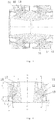
- a bogie suspension vibration reducing system comprises in a bogie 1 a primary suspension system 2, a secondary suspension system 3 and a traction rod system 4.
- the longitudinal stiffness, axial stiffness, torsional stiffness and deflection stiffness of the tumbler node 5 of the primary suspension system are changed in a manner of adjusting the rubber layer thickness of the tumbler node, the angle of a rubber layer bevel, the pre-compression amount of the rubber layer and the structural size of a sheath in metal, so that the longitudinal stiffness and deflection stiffness of the tumbler node 5 are reduced and the transverse load of the vehicle when passing a curve at high speed is reduced.
- the axial stiffness is increased to avoid reducing the torsional stiffness of the tumbler node, such that the longitudinal stiffness of the tumbler node is controlled as 11-13 KN.mm -1 and the axial stiffness is controlled as 6-8 KN.mm -1 , thereby reducing the transverse load of the vehicle when passing the curve at high speed and reducing the wear of the bearing in the axle box.
- the change of the structure of the vertical stopper 6 of the primary suspension system to reduce the vertical stiffness of the primary suspension is realized as follows: a frequent-contact type vertical stopper is adopted; the vertical stopper 6 is in a contact state under no load; therefore, relative slip does not occur between a rubber surface and a framework guide barrel; the stiffness of the vertical stopper is set as nonlinear stiffness; front stiffness is small, and rear stiffness is large; in this way, the derailment risk of the vehicle 8 is avoided, and the steel spring 9 is protected.
- a fulcrum ball hinge with a grooved rubber surface is adopted as the fulcrum ball hinge of the artiroll torsion bar system 7.
- the fulcrum ball hinge comprises an upper-half cover, a lower-half cover and a rubber sleeve arranged between the upper-half cover and the lower-half cover.
- the torsion bar penetrates through the rubber sleeve.
- a tumbler is arranged on one end of the torsion bar, and successively penetrates through the lower-half cover and the upper-half cover and is screwed in a main framework through a connecting bolt.
- a groove is formed in the inner circumferential surface of the rubber sleeve.
- the outer circumferential surface of the torsion bar contacts the groove in the inner circumferential surface of the rubber sleeve.
- the metal spindle of the traction ball hinge has a prism structure with an arc spherical surface.
- the metal jacket is a thin wall metal jacket having a special-shape reinforcing structure.
- the empty direction of the metal spindle, the empty direction of the metal jacket and the empty direction of the rubber elastomer are matched.
- a proper reinforcing structure is designed in the transition region of the metal jacket, to offset the reacting force of the elastomer on the metal jacket, thereby preventing the metal jacket from being deformed after forming or during use.
- Fig. 1 and Fig. 2 show schematic diagrams of the present invention. It can be seen from the figures that, the present invention relates to a method for improving overall performance of a rail vehicle bogie, used to improve overall performance of a secondary suspension bogie of a rail vehicle by changing component structures of a primary suspension system, a secondary suspension system and a traction rod system of the vehicle bogie.
- the primary suspension system adjusts the longitudinal stiffness, axial stiffness, torsional stiffness and deflection stiffness of a tumbler node by changing parameters of adjusting the tumbler node, so that the longitudinal stiffness and deflection stiffness of the tumbler node are reduced and the transverse load of the vehicle when passing a curve at high speed is reduced.
- the axial stiffness is increased to avoid reducing the torsional stiffness of the tumbler node, thereby reducing the wear of a bearing in an axle box.
- the vertical stiffness of the primary suspension is reduced by changing the structure of a vertical stopper.
- an artiroll torsion bar is prevented from generating axial movement by changing the structure of a fulcrum ball hinge of the artiroll torsion bar.
- the nonlinear stiffness of a traction ball hinge is controlled by adjusting the structure of the traction ball hinge of the traction rod system component, so that the traction ball hinge alleviates transitional nonlinear stiffness.
- the longitudinal stiffness, axial stiffness, torsional stiffness and deflection stiffness of the overall bogie are adjusted and the overall performance of the bogie is further improved through the change of the tumbler node and the vertical stopper of the primary suspension system, the structural change of the fulcrum ball hinge of the artiroll torsion bar of the secondary suspension system and the structural change of the traction ball hinge.
- the longitudinal stiffness, axial stiffness, torsional stiffness and deflection stiffness of the tumbler node are adjusted through the adjustment of the parameters of the tumbler node in a manner of adjusting the rubber layer thickness of the tumbler node, the angle of a rubber layer bevel, the pre-compression amount of the rubber layer and the structural size of a sheath in metal, so that the longitudinal stiffness of the tumbler node is controlled as 11-13 KN.mm -1 and the axial stiffness is controlled as 6-8 KN.mm -1 , thereby reducing the transverse load of the vehicle when passing the curve at high speed and reducing the wear of the bearing in the axle box.
- the torsion angle of the tumbler node is computed according to the tumbler length and the vertical deformation of a steel spring; the deflection angle of the tumbler node is computed according to the tumbler length and the transverse deformation of the steel spring; the longitudinal stiffness, the deflection stiffness and the torsional stiffness of the tumbler node are determined according to the torsion angle and the deflection angle of the tumbler node; then, longitudinal stiffness, axial stiffness, torsional stiffness and deflection stiffness required by the tumbler node are computed by using finite element calculation according to the transverse load and the vertical load of the vehicle; and finally, the rubber layer thickness of the tumbler node, the angle of a rubber layer bevel, the pre-compression amount of the rubber layer and the structural size of a sheath in metal are determined according to the longitudinal stiffness, the deflection stiffness, the torsional stiffness and the axial stiffness of the tumbler
- the pre-compression amount of the rubber layer of the tumbler node is controlled as 10-12 mm.
- the lug boss of an inner metal part is prolonged to 5.5-6.5 mm, and a two-section assembly structure is adopted. During assembly, a shell gap of two sections of the tumbler node is adjusted.
- the pressing force ensures that the pressing load is at least larger than 80 kN or is 3 times of the maximum transverse force, so as to increase the axial stiffness of the tumbler node.
- the bevel angle of the rubber layer of the tumbler node is in inverse proportion to the radial stiffness of the tumbler node and is in direct proportion to the axial stiffness.
- the structure sizes of the metal lining and jacket of the tumbler node include: the internal diameter of the tumbler node lining is set as 90-93 mm, and the external diameter is set as 128-132 mm; the internal diameter of the diameter size of the jacket is set as 128-132 mm, and the external diameter is set as 170-173 mm; the matching of the diameter sizes of the tumbler node lining and jacket is ensured so that the longitudinal stiffness of the tumbler node is controlled as 11-13 KN.mm -1 and the axial stiffness is controlled as 6-8 KN.mm -1 , thereby reducing the transverse load of the vehicle when passing the curve at high speed and reducing the wear of the bearing in the axle box.
- the change of the structure of the vertical stopper to reduce the vertical stiffness of the primary suspension is realized as follows: a frequent-contact type vertical stopper is adopted; the vertical stopper is in a contact state under no load; therefore, relative slip does not occur between a rubber surface and a framework guide barrel; the stiffness of the vertical stopper is set as nonlinear stiffness; front stiffness is small, and rear stiffness is large; in this way, the risk of vehicle derailment is avoided, and the steel spring is protected; and meanwhile, a metal hard stopper (base) is arranged, and has the effect of the vertical stopper.
- the vertical stopper controls the abrupt change of the vertical stiffness by controlling the position of a turning point, realizes a curve pattern of the vertical stiffness of a product by adjusting the height size of a rubber profile, the rubber diameter size, the angle size of the rubber profile and the diameter size of the base, obtains different initial stiffnesses and final stiffnesses by adjusting the rubber diameter size and the rubber angle size, controls the sharp trend of the change of the vertical stiffness and controls the vertical stiffness to change in two-stage to multi-stage stiffness by adjusting the angle size of the rubber profile, and controls the size of the vertical stopper by adjusting the height size of the base.
- the change of the structure of the fulcrum ball hinge of the artiroll torsion bar to prevent the artiroll torsion bar from generating axial movement is realized as follows: the structure of the fulcrum ball hinge of the artiroll torsion bar is adjusted to adjust the torsional stiffness and radial pre-pressure, change the rubber volume, adjust the transverse deformation capability, increase axial and transverse positioning stiffness of the torsion rod and prevent the torsion rod from generating axial movement.
- the artiroll torsion bar is prevented from generating axial movement is realized by adjusting the radius size of the rubber layer of the fulcrum ball hinge of the artiroll torsion bar, changing the pre-compression amount between the rubber of the fulcrum ball hinge and the torsion bar axis, adjusting the torsional stiffness and radial pre-pressure on the premise of guaranteeing longitudinal positioning stiffness (radial stiffness), and adjusting the transverse deformation capability by changing the rubber volume; and simultaneously changing the matching with a bulge corresponding to the torsion bar axis through the adjustment of a slot size and a slot shape of the rubber surface, so as to increase the transverse positioning stiffness (axial stiffness) of the torsion bar axis, thereby preventing the axial movement of the torsion bar.
- the nonlinear stiffness of the traction ball hinge is controlled by adjusting the structure of the traction ball hinge of the traction rod system component is realized as follows: an integral metal jacket is prepressed to press the traction ball hinge in the end part of the traction rod, thereby avoiding the problems of rubber wear, rubber cracking and movement of split-structure metal sheath in the ball hinge during a working cycle due to the adoption of an assembly type split-structure traction ball hinge.
- a metal spindle of the traction ball hinge has a prism structure with an arc spherical surface.
- the metal jacket is a thin wall metal jacket having a special-shape reinforcing structure (including triangle, trapezoid or arc, etc.).
- the empty direction of the metal spindle, the empty direction of the metal jacket and the empty direction of a rubber elastomer are matched.
- a proper reinforcing structure is designed in a transition region of the metal jacket, to offset the reacting force of the elastomer on the metal jacket, thereby preventing the metal jacket from being deformed after forming or during use, and reducing or avoiding the wear of a matching surface during installation or reloading of the product due to an oval phenomenon on the excircle of the matching surface; otherwise, it may influence the product life and component life and even result in the problems of product or component failure, etc.
- Embodiment 1 is basically the same as an optical embodiment in structures, but the tumbler node is formed by combining two sections of elastic rubber members with symmetric structures (as shown in Fig. 3 and Fig. 4 ), and comprises a left metal jacket 12 and a left metal lining 11. A left rubber layer 13 is integrally vulcanized between the left metal jacket 12 and the left metal lining 11. The tumbler node also comprises a right metal jacket 14 and a right metal lining 15. A right rubber layer 16 is integrally vulcanized between the right metal jacket 14 and the right metal lining 15.
- Inner holes of the left metal lining 11 and the right metal lining 15 are respectively taper holes which are arranged in opposite directions, i.e., a large head of each taper hole is outside and a small head of each taper hole is inside, and the taper holes are close to each other back to back, wherein the internal diameter D1 of the tumbler node lining is set as 90-93 mm, and the external diameter D3 is set as 128-132 mm; the internal diameter D2 of the diameter size of the jacket is set as 128-132 mm, and the external diameter D4 is set as 170-173 mm; the matching of the diameter sizes of the tumbler node lining and jacket is ensured so that the longitudinal stiffness of the tumbler node is controlled as 11-13 KN.mm -1 and the axial stiffness is controlled as 6-8 KN.mm -1 , thereby reducing the transverse load of the vehicle when passing the curve at high speed and reducing the wear of the bearing in the axle box.
- Both ends of the rubber layer of the tumbler node lining are inwards dug into a ring of annular groove, wherein the depth size H3 of the groove at one end with a small diameter is controlled as 15-30 mm, the depth size H4 of the groove at one end with a large diameter is controlled as 10-20 mm; the form of digging a complete ring of groove not only reduces the radial stiffness of the tumbler node, but also enhances the axial stiffness of the tumbler node so that the longitudinal stiffness of the tumbler node is controlled as 11-13 KN.mm -1 and the axial stiffness is controlled as 6-8 KN.mm -1 , thereby reducing the transverse load of the vehicle when passing the curve at high speed and reducing the wear of the bearing in the axle box. Meanwhile, it is convenient for installation without empty direction.
- the groove is a multi-section deep groove, wherein the first section of groove 17 is a one-sided bevel groove which is concave inwards from a port surface of the rubber layer; in the one-sided bevel groove, one edge is an annular edge parallel to the axis of the tumbler node, and another edge is a first oblique edge which is closed up inwards; the second section of groove 18 is an arc bevel groove having an arc bottom edge.
- one edge is a second oblique edge having a slope identical with that of a bevel of the rubber layer of the tumbler node, the second oblique edge is connected with the first oblique edge of the one-sided bevel groove; another edge of the arc bevel groove is an annular edge connected with the annular edge of the one-sided bevel groove; and the annular edge is connected with the second oblique edge through an arc to form the arc bevel groove.
- the annular edge and the first oblique edge of the one-sided bevel groove are covering edges of the rubber layer of the tumbler node.
- the annular edge and the first oblique edge respectively continue to the end surface of the metal lining and the metal sheath of the tumbler node to form an overall wrap shape.
- the fulcrum ball hinge (as shown in Fig. 5 and Fig. 6 ) of the bogie comprises an upper-half cover 22, a lower-half cover 23 and a rubber sleeve 24 arranged between the upper-half cover 22 and the lower-half cover 23.
- the torsion bar penetrates through the rubber sleeve 24.
- a tumbler is arranged on one end of the torsion bar, and successively penetrates through the lower-half cover 23 and the upper-half cover 22 and is screwed in a main framework through a connecting bolt.
- a groove 27 is formed in the inner circumferential surface of the rubber sleeve 24.
- the outer circumferential surface of the torsion bar 21 contacts the groove 27 in the inner circumferential surface of the rubber sleeve.
- the groove is formed in the inner circumferential surface of the rubber sleeve, so as to reduce the torsional stiffness of the rubber sleeve.
- the rubber sleeve can always conduct torsion together with the torsion bar and the rubber sleeve and the torsion bar may not be loosened, thereby avoiding horizontal movement of the torsion bar.
- the notch of the groove is matched with the outer circumferential surface to form a horizontal limiting structure for the torsion bar, thereby increasing the horizontal positioning stiffness of the torsion bar and further limiting the transverse movement of the torsion bar.
- the groove formed in the inner circumferential surface of the rubber sleeve can accommodate part of inflated and deformed rubber body, thereby reducing the phenomenon of stress concentration herein and enhancing the service life of the rubber sleeve.
- the groove is formed in the inner circumferential surface of the rubber sleeve to reduce the torsional stiffness of the rubber sleeve, and the notch of the groove is matched with the outer circumferential surface of the torsion bar to form a limiting structure to prevent the torsion bar from moving transversely. This is realized through improvement on the existing structure without additionally adding components. The purpose of preventing the torsion bar from moving transversely is achieved, the manufacturing cost is reduced and the installation of the torsion bar is convenient.
- the quantity of the groove 27 is set as one.
- Each groove 27 is configured to be a continuous groove.
- the continuous groove is a groove that extends continuously.
- Each groove 27 is formed in the inner circumferential surface of the rubber sleeve 4 along the circumferential direction, and a plane encircled by each groove 27 is perpendicular to the axis of the torsion bar 21.
- the above structure is designed. When the torsion bar moves transversely, the effect of limiting the transverse movement of the torsion bar through the groove is better.
- the rubber sleeve is in a fifty-fifty structure. On the inner circumferential surface of the rubber sleeve, a complete ring of groove is formed along the circumferential direction.
- the cross section of the groove 27 is a semicircle, and can be set into a trapezoid, a rectangle or a triangle herein.
- the cross section is designed into the semicircle because the semicircle does not have any sharp part and the rubber sleeve may not produce the phenomenon of stress concentration in the sharp part.
- Spacings L are reserved between both ends of the rubber sleeve 24 and between both ends of the upper-half cover 22 and the lower-half cover 23.
- the spacings L are set as 6 mm to 20 mm. In this way, during operation, when the rubber sleeve is inflated and deformed, both ends of the rubber sleeve are protruded outwards, and the protruding positions of the rubber sleeve generate friction with other fittings, thereby damaging the rubber sleeve.
- the set spacings L can prevent both ends from protruding to the outer parts of the upper-half cover and the lower-half cover when the rubber sleeve is inflated and deformed, thereby avoiding the friction between the protruding positions of the rubber sleeve and other fittings and further enhancing the service life of the rubber sleeve.
- Embodiment 2 is basically the same as the optical embodiment in structures, but the fulcrum ball hinge device comprises an upper-half supporting seat and a lower-half supporting seat.
- the upper-half supporting seat is fixedly connected to the vehicle framework.
- the fulcrum ball hinge is disposed between the upper-half supporting seat and the lower-half supporting seat, and successively penetrates through the lower-half supporting seat, the lower-half cover and the upper-half cover and is screwed in the upper-half supporting seat through a connecting bolt, so that the fulcrum ball hinge device is fixedly connected to the vehicle framework.
- Both ends of the rubber layer of the tumbler node lining of the bogie are inwards dug into a ring of annular groove, wherein the depth size H3 of the groove at one end with a small diameter is controlled as 15-30 mm, the depth size H4 of the groove at one end with a large diameter is controlled as 10-20 mm; the form of digging a complete ring of groove not only reduces the radial stiffness of the bogie, but also enhances the axial stiffness of the bogie so that the longitudinal stiffness of the bogie is controlled as 11-13 KN.mm -1 and the axial stiffness is controlled as 6-8 KN.mm -1 , thereby reducing the transverse load of the vehicle when passing the curve at high speed and reducing the wear of the bearing in the axle box.
- the groove is a multi-section deep groove, wherein the first section of groove is a one-sided bevel groove which is concave inwards from a port surface of the rubber layer; in the one-sided bevel groove, one edge is an annular edge parallel to the axis of the bogie, and another edge is a first oblique edge which is closed up inwards; the second section of groove is an arc bevel groove having an arc bottom edge.
- one edge is a second oblique edge having a slope identical with that of a bevel of the rubber layer of the bogie, the second oblique edge is connected with the first oblique edge of the one-sided bevel groove; another edge of the arc bevel groove is an annular edge connected with the annular edge of the one-sided bevel groove; and the annular edge is connected with the second oblique edge through an arc to form the arc bevel groove.
- the annular edge and the first oblique edge of the one-sided bevel groove are covering edges of the rubber layer of the bogie.
- the annular edge and the first oblique edge respectively continue to the end surface of the metal lining and the metal sheath of the bogie to form an overall wrap shape.
- the traction ball hinge of the traction rod system 4 of the bogie alleviates transitional nonlinear stiffness (as shown in Fig. 7 and Fig. 8 ).
- An integral metal jacket is prepressed to press the traction ball hinge in the end part of the traction rod.
- the metal spindle 31 of the traction ball hinge has a prism structure with an arc spherical surface.
- the metal jacket 32 is a thin wall metal jacket having a special-shape reinforcing structure.
- the empty direction of the metal spindle, the empty direction of the metal jacket and the empty direction of the rubber elastomer 33 are matched.
- a proper reinforcing structure 34 is designed in the transition region of the metal jacket, to offset the reacting force of the elastomer on the metal jacket, thereby preventing the metal jacket from being deformed after forming or during use.
- the vertical stopper of the bogie adopts the frequent-contact vertical stopper (as shown in FIG. 9 and FIG. 10 ).
- a locating base 44 is fixed above the axle box 45.
- a dual-coil helical steel spring 42 is arranged above the locating base 44.
- the steel spring 42 supports the locomotive weight above a bogie frame 46.
- the vertical stopper 41 is arranged in the steel spring 42. The convex edge of the base of the vertical stopper 41 is abutted against the locating base 44.
- the vertical stopper 41 and the locating base 44 are gyrators, the vertical stopper 41 can be clamped in the locating base 44.
- a framework guide barrel 43 is arranged directly above the vertical stopper 41.
- the vertical stopper 41 is an axisymmetric gyrator and comprises a rubber body 411, a rubber lug boss 412 and a base 413, while the rubber lug boss 412 comprises a lug boss top 421 and a lug boss outer side 422.
- the rubber lug boss 412 has a circular table shape.
- the included angle between the lug boss top 421 and the lug boss outer side 422 is angle A
- the included angle between the first annular flat segment 411 and a horizontal plane is angle B.
- Angle A and angle B are reduced, so as to increase the range of variable stiffness of the vertical stopper 41. Otherwise, angle A and angle B are increased, so as to reduce the range of variable stiffness of the vertical stopper 41.
- a concave hole 414 is disposed in the middle position of the bottom of the rubber body 11.
- the base 413 is embedded into the rubber body 411. Especially, the base body 413 above the convex edge 432 of the base extends into the rubber body 11.
- the present invention finds that the reason is that structures of elastic elements of a bogie suspension system and selection of performance parameters thereof have problems. Firstly, the tumbler ball hinge causes bearing wear due to too large longitudinal stiffness and deflection stiffness. Secondly, the steel spring of the primary suspension is cracked due to too large vertical stiffness of the primary suspension. Thirdly, the fulcrum ball hinge of the artiroll torsion bar causes lateral movement of the bar body.
- the traction ball hinge as a ball hinge with hollow or solid structure type, or a joint or a similar flexible connecting product has functional opening in the structural direction, after the product is formed, the ex circle of the matching surface is oval or the excircle of the matching surface of the product is oval during use; and then the matching surface is worn and loses the stiffness, and the product life and component life are influenced.
- systematic analysis and study are conducted, and reasons of generating the problems are deeply analyzed, thereby proposing to improve overall performance of a secondary suspension bogie of a rail vehicle by changing component structures of a primary suspension system, a secondary suspension system and a traction rod system of the vehicle bogie.
- the primary suspension system adjusts the longitudinal stiffness, axial stiffness, torsional stiffness and deflection stiffness of a tumbler node by changing parameters of adjusting the tumbler node, so that the longitudinal stiffness and deflection stiffness of the tumbler node are reduced and the transverse load of the vehicle when passing a curve at high speed is reduced. Meanwhile, the axial stiffness is increased to avoid reducing the torsional stiffness of the tumbler node, thereby reducing the wear of an bearing in a axle box.
- the vertical stiffness of the primary suspension is reduced by changing the structure of a vertical stopper.
- an artiroll torsion bar is prevented from generating axial movement by changing the structure of a fulcrum ball hinge of the artiroll torsion bar.
- the nonlinear stiffness of a traction ball hinge is controlled by adjusting the structure of the traction ball hinge of the traction rod system component, so that the traction ball hinge alleviates transitional nonlinear stiffness.
- the longitudinal stiffness, axial stiffness, torsional stiffness and deflection stiffness of the overall bogie are adjusted and the overall performance of the bogie is further improved through the change of the tumbler node and the vertical stopper of the primary suspension system, the structural change of the fulcrum ball hinge of the artiroll torsion bar of the secondary suspension system and the structural change of the traction ball hinge.
- the test proves that this can effectively improve the integral structural performance of the bogie on the whole, and effectively reduce the wear of the axle bearing.
- the present invention takes two-section type conical composite structure, calculates the torsion angle and the deflection angle of the bogie for determining the longitudinal stiffness and the deflection stiffness of the bogie, and determines the bevel of the bogie through the longitudinal stiffness and the deflection stiffness of the bogie, so as to ensure that angle A between each section of bevel of the bogie and the axis is 14-28 degrees, the length L of the rubber layer is 35-60 mm and the thickness H of the rubber layer is 22-30 mm, thereby ensuring that the axial stiffness of the bogie is controlled as 6-8 KN.mm -1 and the radial stiffness is controlled as 11-13 KN.mm -1 , enhancing the axial stiffness of the bogie and reducing the radial stiffness.
- the test proves that the wear of the bearing in the axle box can be effectively prevented or reduced.
- the groove is formed in the inner circumferential surface of the rubber sleeve of the fulcrum ball hinge, so as to reduce the torsional stiffness of the rubber sleeve.
- the notch of the formed groove is matched with the outer circumferential surface of the torsion bar to form a transverse limiting structure of the torsion bar to further limit the transverse movement of the torsion bar.
- the formed groove breaks the continuity of the rubber body, thereby reducing the phenomenon of stress concentration when the rubber body is compressed, inflated and deformed and enhancing the service life of the rubber sleeve.
- the spacings are reserved between both ends of the rubber sleeve and between both ends of the upper-half cover and the lower-half cover, so as to prevent both ends from protruding to the outer parts of the upper-half cover and the lower-half cover when the rubber sleeve is inflated and deformed, thereby avoiding the friction between the protruding positions of the rubber sleeve and other fittings and further enhancing the service life of the rubber sleeve.
- the upper-half supporting seat and the lower-half supporting seat are added, so that the torsion bar can be stably supported and connected to the vehicle framework, thereby better preventing the torsion bar from moving transversely and then ensuring convenient and rapid installation of the torsion bar and increasing the installation efficiency of the artiroll torsion bar.
- a bulge part is arranged on the outer circumferential surface of the torsion bar, and the bulge part on the outer circumferential surface of the torsion bar is matched with the groove in the inner circumferential surface of the rubber body to form a horizontal limiting structure for the torsion bar, thereby increasing the horizontal positioning stiffness of the torsion bar and further limiting the transverse movement of the torsion bar.
- a frequent-contact type vertical stopper is adopted; the vertical stopper is in a contact state under no load; therefore, relative slip does not occur between a rubber surface and a framework guide barrel; the wear of the product is small and the nonlinear degree of the stiffness of the vertical stopper is high; front stiffness is small, and rear stiffness is large; in this way, the risk of vehicle derailment is avoided, and the steel spring is protected.
Abstract
Description
- The present invention relates to an adjusting method and device for performance of locomotive components, and particularly relates to a method and a bogie system for improving overall performance of secondary suspension bogie of a rail vehicle by changing component structures of a primary suspension system, a secondary suspension system and a traction rod system of the vehicle bogie, so as to enhance the overall performance of a rail vehicle bogie. The present invention belongs to the technical field of manufacturing of critical components.
- A vehicle bogie system is one of the most important components in a rail vehicle structure. Various parameters of the bogie also directly decide vehicle stability and riding comfort of the vehicle. The vehicle bogie is an independent component formed by assembling components and devices of a running part of a locomotive. The vehicle bogie plays the action of supporting a vehicle body, a steering device and a brake, and ensures safe and smooth operation of the locomotive on the track. In addition, the locomotive bogie also plays the action of driving. The components that form the bogie include wheel pairs, an axle box device, a spring suspension device, a basic braking device, a framework or side frame, a swing bolster, etc. A driving device is also arranged on the bogie of the locomotive and a motor car. There are many types of bogies. The bogies can be divided into a two-axle bogie, a three-axle bogie and a multi-axle bogie in accordance with the number of axles; and can be divided into a primary spring suspension bogie and a secondary spring suspension bogie in accordance with the suspension mode of the spring.
- At present, high-speed motor cars in China generally adopt the secondary spring suspension bogie. In recent years, for example, (BST) CRH1A-250 style in China and TGV - A high-speed motor cars in France adopt similar bogies. In this kind of bogie system, the components of the primary suspension system, the secondary suspension system and a traction bar system of the bogie are critical portions of the overall system. The performance of the primary suspension system, the secondary suspension system and the traction bar system directly affects the performance of the whole bogie, wherein the primary suspension system is mounted between a bogie frame of the rail vehicle and an axle box to ensure vertical, transverse and longitudinal stiffness of the primary suspension system and transmit acting force in three directions: vertical direction, longitudinal direction and transverse direction. The locomotive weight above the bogie frame is transmitted to the axle box through an axle box spring of the primary suspension, and then transmitted to wheels and steel rails. The stiffness of transmitting the vertical force by the axle box spring is called as the vertical stiffness of the primary suspension. Pulling force or braking force that acts on the circumference of wheel is transmitted to the axle box. The longitudinal force is then transmitted to the bogie frame through the longitudinal stiffness of an axle box locating device. When the locomotive passes through a curve, the transverse force of the steel rail that acts on the wheel pair is transmitted to the framework through the transverse stiffness of the axle box locating device. The stiffness of the primary suspension in three directions (vertical direction, longitudinal direction and transverse direction) shall be selected appropriately so that the locomotive has good dynamics performance. The device mounted between the bogie frame (or side frame) and the swing bolster (or framework and vehicle body) is called as a swing bolster spring device or a central spring device, and also known as a secondary suspension device. The vertical stiffness or static deflection of the secondary suspension is a very important parameter. The locomotives with a speed above 120km per hour are often provided with a traversing device. In recent years, the spring device between the vehicle body and the bogie is also used as the traversing device and is widely applied. The mass of the vehicle body is supported on the bogie through elastic side bearings on the left side and the right side of the bogie frame. The elastic side bearings are composed of round springs or rubber-metal pads and become the secondary suspensions. The effect of the traversing device is played through the transverse elastic displacement of the elastic side bearings. The traction bar system is a connection apparatus between the vehicle body and the bogie. The traction bar system serves as a bearing apparatus for transmitting gravity, and also serves as a traction apparatus for transmitting longitudinal force. The traction bar system can also transmit transverse force, can realize rotation within a certain range and allows the vehicle body to transverse relative to the bogie within a certain range.
- The above primary suspension system, secondary suspension system and traction bar system bear various loads on the vehicle body and the bogie, wherein the vertical load comprises dead weight and load; transverse load comprises wind power and centrifugal force; and longitudinal load comprises pulling force and braking force. In addition, there are also various dynamic loads caused by vehicle vibration and uneven path, including acting force between wheel tracks, etc. These forces shall be transmitted by the primary suspension system, the secondary suspension system and the traction bar system and shall be alleviated and attenuated. It can be seen that the functional performance of the primary suspension system, the secondary suspension system and the traction bar system have important significance to the guarantee of operation smoothness and safety of the vehicle. But in the existing secondary spring suspension bogie (such as (BST) CRH1A-250 style bogie in China), it is found in operation that the axle box bearing of the bogie of the secondary suspension system is worn seriously, which results in the damage to the axle box of the whole bogie and seriously affects the dynamics performance of the locomotive. This will greatly influence normal operation of the vehicle and reduce the service life of the vehicle. Therefore, it is necessary to further study on this.
- There is no report about patent literature with the same technology as the present invention through patent retrieval. There are several patents related to the present invention:
- 1. The PCT patent with the Patent No. of
WO2013091319A1 and the title of HIGH SPEED RAILWAY VEHICLE BOGIE. The patent discloses a secondary spring suspension bogie which is a bogie of a high-speed railway train, including a wheel set, a framework, a primary spring suspension system and a secondary spring suspension system, wherein the framework comprises side beams and a middle cross beam. The middle region of each side beam is a mid-concave portion. Both ends of the middle cross beam are respectively connected with the mid-concave portion of the side beam. The primary spring suspension system comprises primary axle box suspension devices. One end of each primary axle box suspension device is connected with the wheel axle of the wheel set, and the other end is supported on one end of one side beam. The secondary spring suspension system comprises at least two spring groups disposed between the side beams at an interval with the middle cross beam. The upper part of the spring group is connected with one carbody. In the bogie of the high-speed railway train used for the present invention, the spring group of the secondary spring suspension system can provide inherent torque of rotational resistance between the framework and the carbody, thereby increasing linear operation stability, curve negotiation performance and critical speed of the railway train. - 2. The patent for invention with the patent application No. of
CN201110440779.5 - 3. A patent for invention with the Patent No. of
FR8420063 - 4. A patent for invention with the patent No. of
CN201410755469.6 - Although the above patents involve the secondary suspension bogie and propose some improvements of the secondary suspension bogie, the patents only propose some partial improvements, fail to propose how to integrally change the system structure and especially lack of solutions for improving the overall performance of the rail vehicle bogie by changing component structures of the primary suspension system, the secondary suspension system and the traction bar system. As a result, up to now, the bogie of the secondary suspension still has the problem of serious wear of the axle box bearing and needs to be further studied.
Meanwhile, through the study on the wear of the axle bearing of the secondary suspension bogie, it is found that the wear of the axle bearing occurs mainly because the wheel pair generates great transverse load on the steel rail when the vehicle passes through the curve at high speed. Because the tumbler node is a connecting piece that connects the primary tumbler axle and the bogie framework, the tumbler node has great restrictive effect on the axle box and the bearing in the axle box. If the longitudinal (radial) stiffness of the tumbler node is too large, the transverse load of the wheel pair on the steel rail may be further increased. Meanwhile, the steel rail also generates the same transverse reaction on the wheel pair, thereby wearing rims. Similarly, this transverse load also increases the transverse load of the bearing in the axle box, aggravating the bearing wear in the axle box. Therefore, to reduce the bearing wear in the axle box, it is beneficial to appropriately reducing the longitudinal stiffness of the bogie. But if the longitudinal stiffness of the bogie is reduced greatly, the connection restrictive effect for connecting the axle box and the framework in the bogie is influenced. In this way, the vehicle will generate snakelike motion, thereby reducing smoothness and causing derailment in serious cases. Therefore, how to select appropriate longitudinal (radial) stiffness of the bogie becomes the key to effectively prevent the bearing wear in the axle box. The selection of the longitudinal (radial) stiffness of the bogie depends on the selection of a rate of radial stiffness to axial stiffness (abbreviated as ratio of radial/axial stiffness) to a great extent, and generally limited to about 7:1. However, it is found in study that the bogie takes the secondary suspension system structure, has many combined elements, each component generates an effect on the bogie and eccentricity and displacement after system installation are caused due to accumulated tolerance in combined installation, thereby increasing the deflection load of the bogie. This will cause the problem of the wear of the wheel pair, thereby increasing the wear of the bearing in the axle box. In fact, it is insufficient to consider the ratio of radial/axial stiffness only in determining the design of the ratio of radial/axial stiffness of the bogie currently. In practical application, the bogie is a composite bearing element that bears the radial load, the axial load, the deflection load and the torsional load simultaneously. Therefore, the bogie shall be limited from four aspects of radial direction, axial direction, deflection and torsion. - The technical problem of the present invention is to propose a method and a bogie system for improving overall performance of a secondary suspension bogie of a rail vehicle by changing component structures of a primary suspension system, a secondary suspension system and a traction rod system of the vehicle bogie with respect to the problem of easy generation of serious wear of axle box bearing in the existing secondary suspension bogie. The method and the bogie system effectively reduce the wear of the axle box bearing by changing some structures of the primary suspension system, the secondary suspension system and the traction rod system of the vehicle bogie.
- The present invention provides a method for improving overall performance of a rail vehicle bogie, used to improve overall performance of a secondary suspension bogie of a rail vehicle by changing component structures of a primary suspension system, a secondary suspension system and a traction rod system of the vehicle bogie. The primary suspension system adjusts the longitudinal stiffness, axial stiffness, torsional stiffness and deflection stiffness of a tumbler node by changing parameters of adjusting the tumbler node, so that the longitudinal stiffness and deflection stiffness of the tumbler node are reduced and the transverse load of the vehicle when passing a curve at high speed is reduced. Meanwhile, the axial stiffness is increased to avoid reducing the torsional stiffness of the tumbler node, thereby reducing the wear of an bearing in a axle box. In addition, the vertical stiffness of the primary suspension is reduced by changing the structure of a vertical stopper. In the secondary suspension system, an artiroll torsion bar is prevented from generating axial movement by changing the structure of a fulcrum ball hinge of the artiroll torsion bar. The nonlinear stiffness of a traction ball hinge is controlled by adjusting the structure of the traction ball hinge of the traction rod system component, so that the traction ball hinge alleviates transitional nonlinear stiffness. The longitudinal stiffness, axial stiffness, torsional stiffness and deflection stiffness of the overall bogie are adjusted and the overall performance of the bogie is further improved through the change of the tumbler node and the vertical stopper of the primary suspension system, the structural change of the fulcrum ball hinge of the artiroll torsion bar of the secondary suspension system and the structural change of the traction ball hinge.
- Further, the longitudinal stiffness, axial stiffness, torsional stiffness and deflection stiffness of the tumbler node are adjusted through the adjustment of the parameters of the tumbler node in a manner of adjusting the rubber layer thickness of the tumbler node, the angle of a rubber layer bevel, the pre-compression amount of the rubber layer and the structural size of a sheath in metal, so that the longitudinal stiffness of the tumbler node is controlled as 11-13 KN.mm-1 and the axial stiffness is controlled as 6-8 KN.mm-1, thereby reducing the transverse load of the vehicle when passing the curve at high speed and reducing the wear of the bearing in the axle box.
- Further, various parameters of the tumbler node are adjusted as follows: firstly, the torsion angle of the tumbler node is computed according to the tumbler length and the vertical deformation of a steel spring; the deflection angle of the tumbler node is computed according to the tumbler length and the transverse deformation of the steel spring; the longitudinal stiffness, the deflection stiffness and the torsional stiffness of the tumbler node are determined according to the torsion angle and the deflection angle of the tumbler node; then, longitudinal stiffness, axial stiffness, torsional stiffness and deflection stiffness required by the tumbler node are computed by using finite element calculation according to the transverse load and the vertical load of the vehicle; and finally, the rubber layer thickness of the tumbler node, the angle of a rubber layer bevel, the pre-compression amount of the rubber layer and the structural size of a sheath in metal are determined according to the longitudinal stiffness, the deflection stiffness, the torsional stiffness and the axial stiffness of the tumbler node, so that the longitudinal stiffness of the tumbler node is controlled as 11-13 KN.mm-1 and the axial stiffness is controlled as 6-8 KN.mm-1.
- Further, the change of the structure of the vertical stopper to reduce the vertical stiffness of the primary suspension is realized as follows: a frequent-contact type vertical stopper is adopted; the vertical stopper is in a contact state under no load; therefore, relative slip does not occur between a rubber surface and a framework guide barrel; the stiffness of the vertical stopper is set as nonlinear stiffness; front stiffness is small, and rear stiffness is large; in this way, the risk of vehicle derailment is avoided, and the steel spring is protected; and meanwhile, a metal hard stopper (base) is arranged, and has the effect of the vertical stopper.
- Further, the vertical stopper controls the abrupt change of the vertical stiffness by controlling the position of a turning point, realizes a curve pattern of the vertical stiffness of a product by adjusting the height size of a rubber profile, the rubber diameter size, the angle size of the rubber profile and the diameter size of the base, obtains different initial stiffnesses and final stiffnesses by adjusting the rubber diameter size and the rubber angle size, controls the sharp trend of the change of the vertical stiffness and controls the vertical stiffness to change in two-stage to multi-stage stiffness by adjusting the angle size of the rubber profile, and controls the size of the vertical stopper by adjusting the height size of the base.
- Further, the change of the structure of the fulcrum ball hinge of the artiroll torsion bar to prevent the artiroll torsion bar from generating axial movement is realized as follows: the structure of the fulcrum ball hinge of the artiroll torsion bar is adjusted to adjust the torsional stiffness and radial pre-pressure, change the rubber volume, adjust the transverse deformation capability, increase axial and transverse positioning stiffness of the torsion rod and prevent the torsion rod from generating axial movement.
- Further, the artiroll torsion bar is prevented from generating axial movement is realized by adjusting the radius size of the rubber layer of the fulcrum ball hinge of the artiroll torsion bar, changing the pre-compression amount between the rubber of the fulcrum ball hinge and the torsion bar axis, adjusting the torsional stiffness and radial pre-pressure on the premise of guaranteeing longitudinal positioning stiffness (radial stiffness), and adjusting the transverse deformation capability by changing the rubber volume; and simultaneously changing the matching with a bulge corresponding to the torsion bar axis through the adjustment of a slot size and a slot shape of the rubber surface, so as to increase the transverse positioning stiffness (axial stiffness) of the torsion bar axis, thereby preventing the axial movement of the torsion bar.
- Further, the nonlinear stiffness of the traction ball hinge is controlled by adjusting the structure of the traction ball hinge of the traction rod system component is realized as follows: an integral metal jacket is prepressed to press the traction ball hinge in the end part of the traction rod, thereby avoiding the problems of rubber wear, rubber cracking and movement of split-structure metal sheath in the ball hinge during a working cycle due to the adoption of an assembly type split-structure traction ball hinge.
- Further, a metal spindle of the traction ball hinge has a prism structure with an arc spherical surface. The metal jacket is a thin wall metal jacket having a special-shape reinforcing structure (including triangle, trapezoid or arc, etc.). The empty direction of the metal spindle, the empty direction of the metal jacket and the empty direction of a rubber elastomer are matched. A proper reinforcing structure is designed in a transition region of the metal jacket, to offset the reacting force of the elastomer on the metal jacket, thereby preventing the metal jacket from being deformed after forming or during use, and reducing or avoiding the wear of a matching surface during installation or reloading of the product due to an oval phenomenon on the excircle of the matching surface; otherwise, it may influence the product life and component life and even result in the problems of product or component failure, etc.
- A bogie suspension vibration reducing system comprises a primary suspension system, a secondary suspension system and a traction rod system component. The longitudinal stiffness, axial stiffness, torsional stiffness and deflection stiffness of the tumbler node of the primary suspension system are changed in a manner of adjusting the rubber layer thickness of the tumbler node, the angle of a rubber layer bevel, the pre-compression amount of the rubber layer and the structural size of a sheath in metal, so that the longitudinal stiffness and deflection stiffness of the tumbler node are reduced and the transverse load of the vehicle when passing a curve at high speed is reduced. Meanwhile, the axial stiffness is increased to avoid reducing the torsional stiffness of the tumbler node, such that the longitudinal stiffness of the tumbler node is controlled as 11-13 KN.mm-1 and the axial stiffness is controlled as 6-8 KN.mm-1, thereby reducing the transverse load of the vehicle when passing the curve at high speed and reducing the wear of the bearing in the axle box. Meanwhile, the change of the structure of the vertical stopper to reduce the vertical stiffness of the primary suspension is realized as follows: a frequent-contact type vertical stopper is adopted; the vertical stopper is in a contact state under no load; therefore, relative slip does not occur between a rubber surface and a framework guide barrel; the stiffness of the vertical stopper is set as nonlinear stiffness; front stiffness is small, and rear stiffness is large; in this way, the risk of vehicle derailment is avoided, and the steel spring is protected. In the secondary suspension system, a fulcrum ball hinge with a grooved rubber surface is adopted as the fulcrum ball hinge of the artiroll torsion bar. The fulcrum ball hinge comprises an upper-half cover, a lower-half cover and a rubber sleeve arranged between the upper-half cover and the lower-half cover. The torsion bar penetrates through the rubber sleeve. A tumbler is arranged on one end of the torsion bar, and successively penetrates through the lower-half cover and the upper-half cover and is screwed in a main framework through a connecting bolt. A groove is formed in the inner circumferential surface of the rubber sleeve. The outer circumferential surface of the torsion bar contacts the groove in the inner circumferential surface of the rubber sleeve. The traction ball hinge of the traction rod system alleviates transitional nonlinear stiffness. An integral metal jacket is prepressed to press the traction ball hinge in the end part of the traction rod. The metal spindle of the traction ball hinge has a prism structure with an arc spherical surface. The metal jacket is a thin wall metal jacket having a special-shape reinforcing structure. The empty direction of the metal spindle, the empty direction of the metal jacket and the empty direction of the rubber elastomer are matched. A proper reinforcing structure is designed in the transition region of the metal jacket, to offset the reacting force of the elastomer on the metal jacket, thereby preventing the metal jacket from being deformed after forming or during use.
- Further, the tumbler node is formed by combining two sections of elastic rubber members with symmetric structures, and comprises a left metal jacket and a left metal lining. A left rubber layer is integrally vulcanized between the left metal jacket and the left metal lining. The tumbler node also comprises a right metal jacket and a right metal lining. A right rubber layer is integrally vulcanized between the right metal jacket and the right metal lining. The left rubber layer and the right rubber layer are obliquely arranged in opposite directions. Inner holes of the left metal lining and the right metal lining are respectively taper holes which are arranged in opposite directions, wherein the angle between the bevel and the axis of the left rubber layer and the right rubber layer is 14-28 degrees; the bevel length of the left rubber layer and the right rubber layer is 35-60 mm; the internal diameter of the tumbler node lining is set as 90-93 mm, and the external diameter is set as 128-132 mm; the internal diameter of the diameter size of the jacket is set as 128-132 mm, and the external diameter is set as 170-173 mm; the matching of the diameter sizes of the tumbler node lining and jacket is ensured so that the longitudinal stiffness of the tumbler node is controlled as 11-13 KN.mm-1 and the axial stiffness is controlled as 6-8 KN.mm-1; and the longitudinal stiffness is controlled to reduce the deflection stiffness, thereby reducing the transverse load of the vehicle when passing the curve at high speed and reducing the wear of the bearing in the axle box.
- Further, the fulcrum ball hinge device comprises an upper-half supporting seat and a lower-half supporting seat. The upper-half supporting seat is fixedly connected to the vehicle framework. The fulcrum ball hinge is disposed between the upper-half supporting seat and the lower-half supporting seat, and successively penetrates through the lower-half supporting seat, the lower-half cover and the upper-half cover and is screwed in the upper-half supporting seat through a connecting bolt, so that the fulcrum ball hinge device is fixedly connected to the vehicle framework.
- After common problems of CRH1A-250 vehicle bogie used in site are repeatedly studied, the present invention finds that the reason is that structures of elastic elements of a bogie suspension system and selection of performance parameters thereof have problems. Firstly, the tumbler ball hinge causes bearing wear due to too large longitudinal stiffness and deflection stiffness. Secondly, the steel spring of the primary suspension is cracked due to too large vertical stiffness of the primary suspension. Thirdly, the fulcrum ball hinge of the artiroll torsion bar causes lateral movement of the bar body. Further, because the traction ball hinge as a ball hinge with hollow or solid structure type, or a joint or a similar flexible connecting product has functional opening in the structural direction, after the product is formed, the ex circle of the matching surface is oval or the excircle of the matching surface of the product is oval during use; and then the matching surface is worn and loses the stiffness, and the product life and component life are influenced. For the above problems, systematic analysis and study are conducted, and reasons of generating the problems are deeply analyzed, thereby proposing to improve overall performance of a secondary suspension bogie of a rail vehicle by changing component structures of a primary suspension system, a secondary suspension system and a traction rod system of the vehicle bogie. The primary suspension system adjusts the longitudinal stiffness, axial stiffness, torsional stiffness and deflection stiffness of a tumbler node by changing parameters of adjusting the tumbler node, so that the longitudinal stiffness and deflection stiffness of the tumbler node are reduced and the transverse load of the vehicle when passing a curve at high speed is reduced. Meanwhile, the axial stiffness is increased to avoid reducing the torsional stiffness of the tumbler node, thereby reducing the wear of an bearing in a axle box. In addition, the vertical stiffness of the primary suspension is reduced by changing the structure of a vertical stopper. In the secondary suspension system, an artiroll torsion bar is prevented from generating axial movement by changing the structure of a fulcrum ball hinge of the artiroll torsion bar. The nonlinear stiffness of a traction ball hinge is controlled by adjusting the structure of the traction ball hinge of the traction rod system component, so that the traction ball hinge alleviates transitional nonlinear stiffness. The longitudinal stiffness, axial stiffness, torsional stiffness and deflection stiffness of the overall bogie are adjusted and the overall performance of the bogie is further improved through the change of the tumbler node and the vertical stopper of the primary suspension system, the structural change of the fulcrum ball hinge of the artiroll torsion bar of the secondary suspension system and the structural change of the traction ball hinge. The test proves that this can effectively improve the integral structural performance of the bogie on the whole, and effectively reduce the wear of the axle bearing.
-
-
Fig. 1 is a structural schematic diagram of a bogie in an embodiment of the present invention. -
Fig. 2 is a top schematic diagram of a bogie structure inFig. 1 . -
Fig. 3 is a structural schematic diagram of a tumbler node in an embodiment. -
Fig. 4 is a structural schematic diagram of a left node of a tumbler node. -
Fig. 5 is a structural schematic diagram of a fulcrum ball hinge of an artiroll torsion bar in an embodiment. -
Fig. 6 is a structural schematic diagram of a fulcrum ball hinge of an artiroll torsion bar in an embodiment. -
Fig. 7 is a structural schematic diagram of a traction ball hinge in an embodiment. -
Fig. 8 is a structural schematic diagram of a side surface of a traction ball hinge in an embodiment. -
Fig. 9 is a schematic diagram of integral installation of a vertical stopper of a primary suspension in an embodiment. -
Fig. 10 is a structural schematic diagram of a vertical stopper of a primary suspension in an embodiment. -
Fig. 11 is a schematic diagram that the present invention is applied to a specific vehicle bogie. -
Fig. 1 and Fig. 2 show a specific embodiment of the present invention. A bogie suspension vibration reducing system comprises in a bogie 1 aprimary suspension system 2, asecondary suspension system 3 and a traction rod system 4. The longitudinal stiffness, axial stiffness, torsional stiffness and deflection stiffness of thetumbler node 5 of the primary suspension system are changed in a manner of adjusting the rubber layer thickness of the tumbler node, the angle of a rubber layer bevel, the pre-compression amount of the rubber layer and the structural size of a sheath in metal, so that the longitudinal stiffness and deflection stiffness of thetumbler node 5 are reduced and the transverse load of the vehicle when passing a curve at high speed is reduced. Meanwhile, the axial stiffness is increased to avoid reducing the torsional stiffness of the tumbler node, such that the longitudinal stiffness of the tumbler node is controlled as 11-13 KN.mm-1 and the axial stiffness is controlled as 6-8 KN.mm-1, thereby reducing the transverse load of the vehicle when passing the curve at high speed and reducing the wear of the bearing in the axle box. Meanwhile, the change of the structure of thevertical stopper 6 of the primary suspension system to reduce the vertical stiffness of the primary suspension is realized as follows: a frequent-contact type vertical stopper is adopted; thevertical stopper 6 is in a contact state under no load; therefore, relative slip does not occur between a rubber surface and a framework guide barrel; the stiffness of the vertical stopper is set as nonlinear stiffness; front stiffness is small, and rear stiffness is large; in this way, the derailment risk of thevehicle 8 is avoided, and thesteel spring 9 is protected. In the secondary suspension system, a fulcrum ball hinge with a grooved rubber surface is adopted as the fulcrum ball hinge of the artirolltorsion bar system 7. The fulcrum ball hinge comprises an upper-half cover, a lower-half cover and a rubber sleeve arranged between the upper-half cover and the lower-half cover. The torsion bar penetrates through the rubber sleeve. A tumbler is arranged on one end of the torsion bar, and successively penetrates through the lower-half cover and the upper-half cover and is screwed in a main framework through a connecting bolt. A groove is formed in the inner circumferential surface of the rubber sleeve. The outer circumferential surface of the torsion bar contacts the groove in the inner circumferential surface of the rubber sleeve. The traction ball hinge of the traction rod system 4 alleviates transitional nonlinear stiffness. An integral metal jacket is prepressed to press the traction ball hinge in the end part of the traction rod. The metal spindle of the traction ball hinge has a prism structure with an arc spherical surface. The metal jacket is a thin wall metal jacket having a special-shape reinforcing structure. The empty direction of the metal spindle, the empty direction of the metal jacket and the empty direction of the rubber elastomer are matched. A proper reinforcing structure is designed in the transition region of the metal jacket, to offset the reacting force of the elastomer on the metal jacket, thereby preventing the metal jacket from being deformed after forming or during use. - The present invention is further described below in combination with the drawings and the specific embodiments.
-
Fig. 1 and Fig. 2 show schematic diagrams of the present invention. It can be seen from the figures that, the present invention relates to a method for improving overall performance of a rail vehicle bogie, used to improve overall performance of a secondary suspension bogie of a rail vehicle by changing component structures of a primary suspension system, a secondary suspension system and a traction rod system of the vehicle bogie. The primary suspension system adjusts the longitudinal stiffness, axial stiffness, torsional stiffness and deflection stiffness of a tumbler node by changing parameters of adjusting the tumbler node, so that the longitudinal stiffness and deflection stiffness of the tumbler node are reduced and the transverse load of the vehicle when passing a curve at high speed is reduced. Meanwhile, the axial stiffness is increased to avoid reducing the torsional stiffness of the tumbler node, thereby reducing the wear of a bearing in an axle box. In addition, the vertical stiffness of the primary suspension is reduced by changing the structure of a vertical stopper. In the secondary suspension system, an artiroll torsion bar is prevented from generating axial movement by changing the structure of a fulcrum ball hinge of the artiroll torsion bar. The nonlinear stiffness of a traction ball hinge is controlled by adjusting the structure of the traction ball hinge of the traction rod system component, so that the traction ball hinge alleviates transitional nonlinear stiffness. The longitudinal stiffness, axial stiffness, torsional stiffness and deflection stiffness of the overall bogie are adjusted and the overall performance of the bogie is further improved through the change of the tumbler node and the vertical stopper of the primary suspension system, the structural change of the fulcrum ball hinge of the artiroll torsion bar of the secondary suspension system and the structural change of the traction ball hinge. - The longitudinal stiffness, axial stiffness, torsional stiffness and deflection stiffness of the tumbler node are adjusted through the adjustment of the parameters of the tumbler node in a manner of adjusting the rubber layer thickness of the tumbler node, the angle of a rubber layer bevel, the pre-compression amount of the rubber layer and the structural size of a sheath in metal, so that the longitudinal stiffness of the tumbler node is controlled as 11-13 KN.mm-1 and the axial stiffness is controlled as 6-8 KN.mm-1, thereby reducing the transverse load of the vehicle when passing the curve at high speed and reducing the wear of the bearing in the axle box.
- Various parameters of the tumbler node are adjusted as follows: firstly, the torsion angle of the tumbler node is computed according to the tumbler length and the vertical deformation of a steel spring; the deflection angle of the tumbler node is computed according to the tumbler length and the transverse deformation of the steel spring; the longitudinal stiffness, the deflection stiffness and the torsional stiffness of the tumbler node are determined according to the torsion angle and the deflection angle of the tumbler node; then, longitudinal stiffness, axial stiffness, torsional stiffness and deflection stiffness required by the tumbler node are computed by using finite element calculation according to the transverse load and the vertical load of the vehicle; and finally, the rubber layer thickness of the tumbler node, the angle of a rubber layer bevel, the pre-compression amount of the rubber layer and the structural size of a sheath in metal are determined according to the longitudinal stiffness, the deflection stiffness, the torsional stiffness and the axial stiffness of the tumbler node, so that the longitudinal stiffness of the tumbler node is controlled as 11-13 KN.mm-1 and the axial stiffness is controlled as 6-8 KN.mm-1.
- The rubber layer thickness of the tumbler node is in inverse proportion to the longitudinal stiffness, the deflection stiffness and the torsional stiffness of the tumbler node as well as the axial stiffness. Refer to an empirical formula:

- wherein: Ea-correction factor of elastic modulus of axial stiffness;
- Ec-correction factor of elastic modulus of deflection stiffness;
- Et-correction factor of elastic modulus of torsional stiffness;
- Er-correction factor of elastic modulus of longitudinal stiffness;
- Ka-axial stiffness of tumbler node;
- Kc-deflection stiffness of tumbler node;
- Kt-torsional stiffness of tumbler node;
- Kr-longitudinal stiffness of tumbler node;
- The pre-compression amount of the rubber layer of the tumbler node is controlled as 10-12 mm. The lug boss of an inner metal part is prolonged to 5.5-6.5 mm, and a two-section assembly structure is adopted. During assembly, a shell gap of two sections of the tumbler node is adjusted. The pressing force ensures that the pressing load is at least larger than 80 kN or is 3 times of the maximum transverse force, so as to increase the axial stiffness of the tumbler node.
- The bevel angle of the rubber layer of the tumbler node is in inverse proportion to the radial stiffness of the tumbler node and is in direct proportion to the axial stiffness. The relational expression is as follows:

- wherein: Ea-correction factor of elastic modulus of axial stiffness;
- Er-correction factor of elastic modulus of longitudinal stiffness;
- Ka-axial stiffness of tumbler node;
- Kr-longitudinal stiffness of tumbler node;
- The structure sizes of the metal lining and jacket of the tumbler node include: the internal diameter of the tumbler node lining is set as 90-93 mm, and the external diameter is set as 128-132 mm; the internal diameter of the diameter size of the jacket is set as 128-132 mm, and the external diameter is set as 170-173 mm; the matching of the diameter sizes of the tumbler node lining and jacket is ensured so that the longitudinal stiffness of the tumbler node is controlled as 11-13 KN.mm-1 and the axial stiffness is controlled as 6-8 KN.mm-1, thereby reducing the transverse load of the vehicle when passing the curve at high speed and reducing the wear of the bearing in the axle box.
- The change of the structure of the vertical stopper to reduce the vertical stiffness of the primary suspension is realized as follows: a frequent-contact type vertical stopper is adopted; the vertical stopper is in a contact state under no load; therefore, relative slip does not occur between a rubber surface and a framework guide barrel; the stiffness of the vertical stopper is set as nonlinear stiffness; front stiffness is small, and rear stiffness is large; in this way, the risk of vehicle derailment is avoided, and the steel spring is protected; and meanwhile, a metal hard stopper (base) is arranged, and has the effect of the vertical stopper.
- The vertical stopper controls the abrupt change of the vertical stiffness by controlling the position of a turning point, realizes a curve pattern of the vertical stiffness of a product by adjusting the height size of a rubber profile, the rubber diameter size, the angle size of the rubber profile and the diameter size of the base, obtains different initial stiffnesses and final stiffnesses by adjusting the rubber diameter size and the rubber angle size, controls the sharp trend of the change of the vertical stiffness and controls the vertical stiffness to change in two-stage to multi-stage stiffness by adjusting the angle size of the rubber profile, and controls the size of the vertical stopper by adjusting the height size of the base.
- The change of the structure of the fulcrum ball hinge of the artiroll torsion bar to prevent the artiroll torsion bar from generating axial movement is realized as follows: the structure of the fulcrum ball hinge of the artiroll torsion bar is adjusted to adjust the torsional stiffness and radial pre-pressure, change the rubber volume, adjust the transverse deformation capability, increase axial and transverse positioning stiffness of the torsion rod and prevent the torsion rod from generating axial movement.
- The artiroll torsion bar is prevented from generating axial movement is realized by adjusting the radius size of the rubber layer of the fulcrum ball hinge of the artiroll torsion bar, changing the pre-compression amount between the rubber of the fulcrum ball hinge and the torsion bar axis, adjusting the torsional stiffness and radial pre-pressure on the premise of guaranteeing longitudinal positioning stiffness (radial stiffness), and adjusting the transverse deformation capability by changing the rubber volume; and simultaneously changing the matching with a bulge corresponding to the torsion bar axis through the adjustment of a slot size and a slot shape of the rubber surface, so as to increase the transverse positioning stiffness (axial stiffness) of the torsion bar axis, thereby preventing the axial movement of the torsion bar.
- The nonlinear stiffness of the traction ball hinge is controlled by adjusting the structure of the traction ball hinge of the traction rod system component is realized as follows: an integral metal jacket is prepressed to press the traction ball hinge in the end part of the traction rod, thereby avoiding the problems of rubber wear, rubber cracking and movement of split-structure metal sheath in the ball hinge during a working cycle due to the adoption of an assembly type split-structure traction ball hinge.
- A metal spindle of the traction ball hinge has a prism structure with an arc spherical surface. The metal jacket is a thin wall metal jacket having a special-shape reinforcing structure (including triangle, trapezoid or arc, etc.). The empty direction of the metal spindle, the empty direction of the metal jacket and the empty direction of a rubber elastomer are matched. A proper reinforcing structure is designed in a transition region of the metal jacket, to offset the reacting force of the elastomer on the metal jacket, thereby preventing the metal jacket from being deformed after forming or during use, and reducing or avoiding the wear of a matching surface during installation or reloading of the product due to an oval phenomenon on the excircle of the matching surface; otherwise, it may influence the product life and component life and even result in the problems of product or component failure, etc.
-
Embodiment 1 is basically the same as an optical embodiment in structures, but the tumbler node is formed by combining two sections of elastic rubber members with symmetric structures (as shown inFig. 3 and Fig. 4 ), and comprises aleft metal jacket 12 and aleft metal lining 11. Aleft rubber layer 13 is integrally vulcanized between theleft metal jacket 12 and theleft metal lining 11. The tumbler node also comprises aright metal jacket 14 and aright metal lining 15. Aright rubber layer 16 is integrally vulcanized between theright metal jacket 14 and theright metal lining 15. Inner holes of theleft metal lining 11 and theright metal lining 15 are respectively taper holes which are arranged in opposite directions, i.e., a large head of each taper hole is outside and a small head of each taper hole is inside, and the taper holes are close to each other back to back, wherein the internal diameter D1 of the tumbler node lining is set as 90-93 mm, and the external diameter D3 is set as 128-132 mm; the internal diameter D2 of the diameter size of the jacket is set as 128-132 mm, and the external diameter D4 is set as 170-173 mm; the matching of the diameter sizes of the tumbler node lining and jacket is ensured so that the longitudinal stiffness of the tumbler node is controlled as 11-13 KN.mm-1 and the axial stiffness is controlled as 6-8 KN.mm-1, thereby reducing the transverse load of the vehicle when passing the curve at high speed and reducing the wear of the bearing in the axle box. - Both ends of the rubber layer of the tumbler node lining are inwards dug into a ring of annular groove, wherein the depth size H3 of the groove at one end with a small diameter is controlled as 15-30 mm, the depth size H4 of the groove at one end with a large diameter is controlled as 10-20 mm; the form of digging a complete ring of groove not only reduces the radial stiffness of the tumbler node, but also enhances the axial stiffness of the tumbler node so that the longitudinal stiffness of the tumbler node is controlled as 11-13 KN.mm-1 and the axial stiffness is controlled as 6-8 KN.mm-1, thereby reducing the transverse load of the vehicle when passing the curve at high speed and reducing the wear of the bearing in the axle box. Meanwhile, it is convenient for installation without empty direction.
- The groove is a multi-section deep groove, wherein the first section of
groove 17 is a one-sided bevel groove which is concave inwards from a port surface of the rubber layer; in the one-sided bevel groove, one edge is an annular edge parallel to the axis of the tumbler node, and another edge is a first oblique edge which is closed up inwards; the second section ofgroove 18 is an arc bevel groove having an arc bottom edge. In the arc bevel groove, one edge is a second oblique edge having a slope identical with that of a bevel of the rubber layer of the tumbler node, the second oblique edge is connected with the first oblique edge of the one-sided bevel groove; another edge of the arc bevel groove is an annular edge connected with the annular edge of the one-sided bevel groove; and the annular edge is connected with the second oblique edge through an arc to form the arc bevel groove. - The annular edge and the first oblique edge of the one-sided bevel groove are covering edges of the rubber layer of the tumbler node. The annular edge and the first oblique edge respectively continue to the end surface of the metal lining and the metal sheath of the tumbler node to form an overall wrap shape.
- The fulcrum ball hinge (as shown in
Fig. 5 and Fig. 6 ) of the bogie comprises an upper-half cover 22, a lower-half cover 23 and arubber sleeve 24 arranged between the upper-half cover 22 and the lower-half cover 23. The torsion bar penetrates through therubber sleeve 24. A tumbler is arranged on one end of the torsion bar, and successively penetrates through the lower-half cover 23 and the upper-half cover 22 and is screwed in a main framework through a connecting bolt. Agroove 27 is formed in the inner circumferential surface of therubber sleeve 24. The outer circumferential surface of thetorsion bar 21 contacts thegroove 27 in the inner circumferential surface of the rubber sleeve. The groove is formed in the inner circumferential surface of the rubber sleeve, so as to reduce the torsional stiffness of the rubber sleeve. When the vehicle body rolls, the rubber sleeve can always conduct torsion together with the torsion bar and the rubber sleeve and the torsion bar may not be loosened, thereby avoiding horizontal movement of the torsion bar. In addition, the notch of the groove is matched with the outer circumferential surface to form a horizontal limiting structure for the torsion bar, thereby increasing the horizontal positioning stiffness of the torsion bar and further limiting the transverse movement of the torsion bar. When the rubber sleeve is compressed, inflated and deformed, the groove formed in the inner circumferential surface of the rubber sleeve can accommodate part of inflated and deformed rubber body, thereby reducing the phenomenon of stress concentration herein and enhancing the service life of the rubber sleeve. The groove is formed in the inner circumferential surface of the rubber sleeve to reduce the torsional stiffness of the rubber sleeve, and the notch of the groove is matched with the outer circumferential surface of the torsion bar to form a limiting structure to prevent the torsion bar from moving transversely. This is realized through improvement on the existing structure without additionally adding components. The purpose of preventing the torsion bar from moving transversely is achieved, the manufacturing cost is reduced and the installation of the torsion bar is convenient. - The quantity of the
groove 27 is set as one. Eachgroove 27 is configured to be a continuous groove. The continuous groove is a groove that extends continuously. Eachgroove 27 is formed in the inner circumferential surface of the rubber sleeve 4 along the circumferential direction, and a plane encircled by eachgroove 27 is perpendicular to the axis of thetorsion bar 21. The above structure is designed. When the torsion bar moves transversely, the effect of limiting the transverse movement of the torsion bar through the groove is better. The rubber sleeve is in a fifty-fifty structure. On the inner circumferential surface of the rubber sleeve, a complete ring of groove is formed along the circumferential direction. - The cross section of the
groove 27 is a semicircle, and can be set into a trapezoid, a rectangle or a triangle herein. The cross section is designed into the semicircle because the semicircle does not have any sharp part and the rubber sleeve may not produce the phenomenon of stress concentration in the sharp part. - Spacings L are reserved between both ends of the
rubber sleeve 24 and between both ends of the upper-half cover 22 and the lower-half cover 23. The spacings L are set as 6 mm to 20 mm. In this way, during operation, when the rubber sleeve is inflated and deformed, both ends of the rubber sleeve are protruded outwards, and the protruding positions of the rubber sleeve generate friction with other fittings, thereby damaging the rubber sleeve. In the present embodiment, the set spacings L can prevent both ends from protruding to the outer parts of the upper-half cover and the lower-half cover when the rubber sleeve is inflated and deformed, thereby avoiding the friction between the protruding positions of the rubber sleeve and other fittings and further enhancing the service life of the rubber sleeve. -
Embodiment 2 is basically the same as the optical embodiment in structures, but the fulcrum ball hinge device comprises an upper-half supporting seat and a lower-half supporting seat. The upper-half supporting seat is fixedly connected to the vehicle framework. The fulcrum ball hinge is disposed between the upper-half supporting seat and the lower-half supporting seat, and successively penetrates through the lower-half supporting seat, the lower-half cover and the upper-half cover and is screwed in the upper-half supporting seat through a connecting bolt, so that the fulcrum ball hinge device is fixedly connected to the vehicle framework. - Both ends of the rubber layer of the tumbler node lining of the bogie are inwards dug into a ring of annular groove, wherein the depth size H3 of the groove at one end with a small diameter is controlled as 15-30 mm, the depth size H4 of the groove at one end with a large diameter is controlled as 10-20 mm; the form of digging a complete ring of groove not only reduces the radial stiffness of the bogie, but also enhances the axial stiffness of the bogie so that the longitudinal stiffness of the bogie is controlled as 11-13 KN.mm-1 and the axial stiffness is controlled as 6-8 KN.mm-1, thereby reducing the transverse load of the vehicle when passing the curve at high speed and reducing the wear of the bearing in the axle box. Meanwhile, it is convenient for installation without empty direction. The groove is a multi-section deep groove, wherein the first section of groove is a one-sided bevel groove which is concave inwards from a port surface of the rubber layer; in the one-sided bevel groove, one edge is an annular edge parallel to the axis of the bogie, and another edge is a first oblique edge which is closed up inwards; the second section of groove is an arc bevel groove having an arc bottom edge. In the arc bevel groove, one edge is a second oblique edge having a slope identical with that of a bevel of the rubber layer of the bogie, the second oblique edge is connected with the first oblique edge of the one-sided bevel groove; another edge of the arc bevel groove is an annular edge connected with the annular edge of the one-sided bevel groove; and the annular edge is connected with the second oblique edge through an arc to form the arc bevel groove. The annular edge and the first oblique edge of the one-sided bevel groove are covering edges of the rubber layer of the bogie. The annular edge and the first oblique edge respectively continue to the end surface of the metal lining and the metal sheath of the bogie to form an overall wrap shape.
- The traction ball hinge of the traction rod system 4 of the bogie alleviates transitional nonlinear stiffness (as shown in
Fig. 7 and Fig. 8 ). An integral metal jacket is prepressed to press the traction ball hinge in the end part of the traction rod. Themetal spindle 31 of the traction ball hinge has a prism structure with an arc spherical surface. Themetal jacket 32 is a thin wall metal jacket having a special-shape reinforcing structure. The empty direction of the metal spindle, the empty direction of the metal jacket and the empty direction of therubber elastomer 33 are matched. A proper reinforcingstructure 34 is designed in the transition region of the metal jacket, to offset the reacting force of the elastomer on the metal jacket, thereby preventing the metal jacket from being deformed after forming or during use. - The vertical stopper of the bogie adopts the frequent-contact vertical stopper (as shown in
FIG. 9 andFIG. 10 ). A locating base 44 is fixed above theaxle box 45. A dual-coilhelical steel spring 42 is arranged above the locating base 44. Thesteel spring 42 supports the locomotive weight above abogie frame 46. To reduce the vertical load borne by thesteel spring 42 and reduce metal fatigue generated by thesteel spring 42 in the operation process of the locomotive to prevent thesteel spring 42 from being broken, thevertical stopper 41 is arranged in thesteel spring 42. The convex edge of the base of thevertical stopper 41 is abutted against the locating base 44. Because thevertical stopper 41 and the locating base 44 are gyrators, thevertical stopper 41 can be clamped in the locating base 44. Aframework guide barrel 43 is arranged directly above thevertical stopper 41. When the locomotive has no load, the rubber lug boss of thevertical stopper 41 contacts theframework guide barrel 43, and in the whole process of the locomotive from no load to the maximum load, the load of the primary suspension system is supported jointly by thesteel spring 42 and thevertical stopper 41, so that thevertical stopper 41 can better reduce the vertical load borne by thesteel spring 42. - The
vertical stopper 41 is an axisymmetric gyrator and comprises arubber body 411, arubber lug boss 412 and abase 413, while therubber lug boss 412 comprises alug boss top 421 and a lug bossouter side 422. Therubber lug boss 412 has a circular table shape. The included angle between thelug boss top 421 and the lug bossouter side 422 is angle A, and the included angle between the first annularflat segment 411 and a horizontal plane is angle B. Angle A and angle B are reduced, so as to increase the range of variable stiffness of thevertical stopper 41. Otherwise, angle A and angle B are increased, so as to reduce the range of variable stiffness of thevertical stopper 41. To reduce consumptive material of the rubber, aconcave hole 414 is disposed in the middle position of the bottom of therubber body 11. Thebase 413 is embedded into therubber body 411. Especially, thebase body 413 above theconvex edge 432 of the base extends into therubber body 11. - The above described embodiments only clearly and completely describe the technical solution of the present invention in combination with drawings. Apparently, the described embodiments are merely part of the embodiments of the present invention, not all of the embodiments. Based on the embodiments in the present invention, all other embodiments obtained by those ordinary skilled in the art without contributing creative labor will belong to the protection scope of the present invention.
- After common problems of CRH1A-250 vehicle bogie used in site are repeatedly studied, the present invention finds that the reason is that structures of elastic elements of a bogie suspension system and selection of performance parameters thereof have problems. Firstly, the tumbler ball hinge causes bearing wear due to too large longitudinal stiffness and deflection stiffness. Secondly, the steel spring of the primary suspension is cracked due to too large vertical stiffness of the primary suspension. Thirdly, the fulcrum ball hinge of the artiroll torsion bar causes lateral movement of the bar body. Further, because the traction ball hinge as a ball hinge with hollow or solid structure type, or a joint or a similar flexible connecting product has functional opening in the structural direction, after the product is formed, the ex circle of the matching surface is oval or the excircle of the matching surface of the product is oval during use; and then the matching surface is worn and loses the stiffness, and the product life and component life are influenced. For the above problems, systematic analysis and study are conducted, and reasons of generating the problems are deeply analyzed, thereby proposing to improve overall performance of a secondary suspension bogie of a rail vehicle by changing component structures of a primary suspension system, a secondary suspension system and a traction rod system of the vehicle bogie. The primary suspension system adjusts the longitudinal stiffness, axial stiffness, torsional stiffness and deflection stiffness of a tumbler node by changing parameters of adjusting the tumbler node, so that the longitudinal stiffness and deflection stiffness of the tumbler node are reduced and the transverse load of the vehicle when passing a curve at high speed is reduced. Meanwhile, the axial stiffness is increased to avoid reducing the torsional stiffness of the tumbler node, thereby reducing the wear of an bearing in a axle box. In addition, the vertical stiffness of the primary suspension is reduced by changing the structure of a vertical stopper. In the secondary suspension system, an artiroll torsion bar is prevented from generating axial movement by changing the structure of a fulcrum ball hinge of the artiroll torsion bar. The nonlinear stiffness of a traction ball hinge is controlled by adjusting the structure of the traction ball hinge of the traction rod system component, so that the traction ball hinge alleviates transitional nonlinear stiffness. The longitudinal stiffness, axial stiffness, torsional stiffness and deflection stiffness of the overall bogie are adjusted and the overall performance of the bogie is further improved through the change of the tumbler node and the vertical stopper of the primary suspension system, the structural change of the fulcrum ball hinge of the artiroll torsion bar of the secondary suspension system and the structural change of the traction ball hinge. The test proves that this can effectively improve the integral structural performance of the bogie on the whole, and effectively reduce the wear of the axle bearing.
- Firstly, through the analytical study of many solutions, it is proposed to improve the longitudinal stiffness and the deflection stiffness of the bogie, adjust the positioning of the tumbler type axle box, reduce the transverse load when the vehicle passes through the curve at high speed and prevent or reduce the wear of the bearing in the axle box. The present invention takes two-section type conical composite structure, calculates the torsion angle and the deflection angle of the bogie for determining the longitudinal stiffness and the deflection stiffness of the bogie, and determines the bevel of the bogie through the longitudinal stiffness and the deflection stiffness of the bogie, so as to ensure that angle A between each section of bevel of the bogie and the axis is 14-28 degrees, the length L of the rubber layer is 35-60 mm and the thickness H of the rubber layer is 22-30 mm, thereby ensuring that the axial stiffness of the bogie is controlled as 6-8 KN.mm-1 and the radial stiffness is controlled as 11-13 KN.mm-1, enhancing the axial stiffness of the bogie and reducing the radial stiffness. The test proves that the wear of the bearing in the axle box can be effectively prevented or reduced.
- Secondly, the groove is formed in the inner circumferential surface of the rubber sleeve of the fulcrum ball hinge, so as to reduce the torsional stiffness of the rubber sleeve. Thus, when the vehicle body rolls, the rubber sleeve can always conduct torsion together with the torsion bar and the rubber sleeve and the torsion bar may not be loosened, thereby avoiding horizontal movement of the torsion bar. The notch of the formed groove is matched with the outer circumferential surface of the torsion bar to form a transverse limiting structure of the torsion bar to further limit the transverse movement of the torsion bar. The present invention is realized through improvement on the existing structure without additionally adding components. The purpose of preventing the torsion bar from moving transversely is achieved, the manufacturing cost is reduced and the installation of the torsion bar is convenient. In addition, the formed groove breaks the continuity of the rubber body, thereby reducing the phenomenon of stress concentration when the rubber body is compressed, inflated and deformed and enhancing the service life of the rubber sleeve. The spacings are reserved between both ends of the rubber sleeve and between both ends of the upper-half cover and the lower-half cover, so as to prevent both ends from protruding to the outer parts of the upper-half cover and the lower-half cover when the rubber sleeve is inflated and deformed, thereby avoiding the friction between the protruding positions of the rubber sleeve and other fittings and further enhancing the service life of the rubber sleeve. In the present invention, in the fulcrum ball hinge device, the upper-half supporting seat and the lower-half supporting seat are added, so that the torsion bar can be stably supported and connected to the vehicle framework, thereby better preventing the torsion bar from moving transversely and then ensuring convenient and rapid installation of the torsion bar and increasing the installation efficiency of the artiroll torsion bar. A bulge part is arranged on the outer circumferential surface of the torsion bar, and the bulge part on the outer circumferential surface of the torsion bar is matched with the groove in the inner circumferential surface of the rubber body to form a horizontal limiting structure for the torsion bar, thereby increasing the horizontal positioning stiffness of the torsion bar and further limiting the transverse movement of the torsion bar.
- Further, a frequent-contact type vertical stopper is adopted; the vertical stopper is in a contact state under no load; therefore, relative slip does not occur between a rubber surface and a framework guide barrel; the wear of the product is small and the nonlinear degree of the stiffness of the vertical stopper is high; front stiffness is small, and rear stiffness is large; in this way, the risk of vehicle derailment is avoided, and the steel spring is protected.
Claims (12)
- A method for improving overall performance of a rail vehicle bogie, characterized in that to improve overall performance of a secondary suspension bogie of a rail vehicle by changing component structures of a primary suspension system, a secondary suspension system and a traction rod system of the vehicle bogie. The primary suspension system adjusts the longitudinal stiffness, axial stiffness, torsional stiffness and deflection stiffness of a tumbler node by changing parameters of adjusting the tumbler node, so that the longitudinal stiffness and deflection stiffness of the tumbler node are reduced and the transverse load of the vehicle when passing a curve at high speed is reduced. Meanwhile, the axial stiffness is increased to avoid reducing the torsional stiffness of the tumbler node, thereby reducing the wear of an bearing in a axle box. In addition, the vertical stiffness of the primary suspension is reduced by changing the structure of a vertical stopper. In the secondary suspension system, an artiroll torsion bar is prevented from generating axial movement by changing the structure of a fulcrum ball hinge of the artiroll torsion bar. The nonlinear stiffness of a traction ball hinge is controlled by adjusting the structure of the traction ball hinge of the traction rod system component, so that the traction ball hinge alleviates transitional nonlinear stiffness. The longitudinal stiffness, axial stiffness, torsional stiffness and deflection stiffness of the overall bogie are adjusted and the overall performance of the bogie is further improved through the change of the tumbler node and the vertical stopper of the primary suspension system, the structural change of the fulcrum ball hinge of the artiroll torsion bar of the secondary suspension system and the structural change of the traction ball hinge.
- The method for improving overall performance of a rail vehicle bogie according to claim 1, characterized in that the longitudinal stiffness, axial stiffness, torsional stiffness and deflection stiffness of the tumbler node are adjusted through the adjustment of the parameters of the tumbler node in a manner of adjusting the rubber layer thickness of the tumbler node, the angle of a rubber layer bevel, the pre-compression amount of the rubber layer and the structural size of a sheath in metal, so that the longitudinal stiffness of the tumbler node is controlled as 11-13 KN.mm-1 and the axial stiffness is controlled as 6-8 KN.mm-1, thereby reducing the transverse load of the vehicle when passing the curve at high speed and reducing the wear of the bearing in the axle box.
- The method for improving overall performance of a rail vehicle bogie according to claim 2, characterized in that various parameters of the tumbler node are adjusted as follows: firstly, the torsion angle of the tumbler node is computed according to the tumbler length and the vertical deformation of a steel spring; the deflection angle of the tumbler node is computed according to the tumbler length and the transverse deformation of the steel spring; the longitudinal stiffness, the deflection stiffness and the torsional stiffness of the tumbler node are determined according to the torsion angle and the deflection angle of the tumbler node; then, longitudinal stiffness, axial stiffness, torsional stiffness and deflection stiffness required by the tumbler node are computed by using finite element calculation according to the transverse load and the vertical load of the vehicle; and finally, the rubber layer thickness of the tumbler node, the angle of a rubber layer bevel, the pre-compression amount of the rubber layer and the structural size of a sheath in metal are determined according to the longitudinal stiffness, the deflection stiffness, the torsional stiffness and the axial stiffness of the tumbler node, so that the longitudinal stiffness of the tumbler node is controlled as 11-13 KN.mm-1 and the axial stiffness is controlled as 6-8 KN.mm-1.
- The method for improving overall performance of a rail vehicle bogie according to claim 1, characterized in that the change of the structure of the vertical stopper to reduce the vertical stiffness of the primary suspension is realized as follows: a frequent-contact type vertical stopper is adopted; the vertical stopper is in a contact state under no load; therefore, relative slip does not occur between a rubber surface and a framework guide barrel; the stiffness of the vertical stopper is set as nonlinear stiffness; front stiffness is small, and rear stiffness is large; in this way, the risk of vehicle derailment is avoided, and the steel spring is protected; and meanwhile, a metal hard stopper (base) is arranged, and has the effect of the vertical stopper.
- The method for improving overall performance of a rail vehicle bogie according to claim 4, characterized in that the vertical stopper controls the abrupt change of the vertical stiffness by controlling the position of a turning point, realizes a curve pattern of the vertical stiffness of a product by adjusting the height size of a rubber profile, the rubber diameter size, the angle size of the rubber profile and the diameter size of the base, obtains different initial stiffnesses and final stiffnesses by adjusting the rubber diameter size and the rubber angle size, controls the sharp trend of the change of the vertical stiffness and controls the vertical stiffness to change in two-stage to multi-stage stiffness by adjusting the angle size of the rubber profile, and controls the size of the vertical stopper by adjusting the height size of the base.
- The method for improving overall performance of a rail vehicle bogie according to claim 5, characterized in that the change of the structure of the fulcrum ball hinge of the artiroll torsion bar to prevent the artiroll torsion bar from generating axial movement is realized as follows: the structure of the fulcrum ball hinge of the artiroll torsion bar is adjusted to adjust the torsional stiffness and radial pre-pressure, change the rubber volume, adjust the transverse deformation capability, increase axial and transverse positioning stiffness of the torsion rod and prevent the torsion rod from generating axial movement.
- The method for improving overall performance of a rail vehicle bogie according to claim 6, characterized in that the artiroll torsion bar is prevented from generating axial movement is realized by adjusting the radius size of the rubber layer of the fulcrum ball hinge of the artiroll torsion bar, changing the pre-compression amount between the rubber of the fulcrum ball hinge and the torsion bar axis, adjusting the torsional stiffness and radial pre-pressure on the premise of guaranteeing longitudinal positioning stiffness (radial stiffness), and adjusting the transverse deformation capability by changing the rubber volume; and simultaneously changing the matching with a bulge corresponding to the torsion bar axis through the adjustment of a slot size and a slot shape of the rubber surface, so as to increase the transverse positioning stiffness (axial stiffness) of the torsion bar axis, thereby preventing the axial movement of the torsion bar.
- The method for improving overall performance of a rail vehicle bogie according to claim 1, characterized in that the nonlinear stiffness of the traction ball hinge is controlled by adjusting the structure of the traction ball hinge of the traction rod system component is realized as follows: an integral metal jacket is prepressed to press the traction ball hinge in the end part of the traction rod, thereby avoiding the problems of rubber wear, rubber cracking and movement of split-structure metal sheath in the ball hinge during a working cycle due to the adoption of an assembly type split-structure traction ball hinge.
- The method for improving overall performance of a rail vehicle bogie according to claim 8, characterized in that a metal spindle of the traction ball hinge has a prism structure with an arc spherical surface. The metal jacket is a thin wall metal jacket having a special-shape reinforcing structure. The empty direction of the metal spindle, the empty direction of the metal jacket and the empty direction of a rubber elastomer are matched. A proper reinforcing structure is designed in a transition region of the metal jacket, to offset the reacting force of the elastomer on the metal jacket, thereby preventing the metal jacket from being deformed after forming or during use, and reducing or avoiding the wear of a matching surface during installation or reloading of the product due to an oval phenomenon on the excircle of the matching surface; otherwise, it may influence the product life and component life and even result in the problems of product or component failure, etc.
- A bogie suspension vibration reducing system, comprises a primary suspension system, a secondary suspension system and a traction rod system, improves overall performance of a secondary suspension bogie of a rail vehicle by changing component structures of the primary suspension system, the secondary suspension system and the traction rod system, characterized in that the longitudinal stiffness, axial stiffness, torsional stiffness and deflection stiffness of the tumbler node of the primary suspension system are changed in a manner of adjusting the rubber layer thickness of the tumbler node, the angle of a rubber layer bevel, the pre-compression amount of the rubber layer and the structural size of a sheath in metal, so that the longitudinal stiffness and deflection stiffness of the tumbler node are reduced and the transverse load of the vehicle when passing a curve at high speed is reduced. Meanwhile, the axial stiffness is increased to avoid reducing the torsional stiffness of the tumbler node, such that the longitudinal stiffness of the tumbler node is controlled as 11-13 KN.mm-1 and the axial stiffness is controlled as 6-8 KN.mm-1, thereby reducing the transverse load of the vehicle when passing the curve at high speed and reducing the wear of the bearing in the axle box. Meanwhile, the change of the structure of the vertical stopper to reduce the vertical stiffness of the primary suspension is realized as follows: a frequent-contact type vertical stopper is adopted; the vertical stopper is in a contact state under no load; therefore, relative slip does not occur between a rubber surface and a framework guide barrel; the stiffness of the vertical stopper is set as nonlinear stiffness; front stiffness is small, and rear stiffness is large; in this way, the risk of vehicle derailment is avoided, and the steel spring is protected. In the secondary suspension system, a fulcrum ball hinge with a grooved rubber surface is adopted as the fulcrum ball hinge of the artiroll torsion bar. The fulcrum ball hinge comprises an upper-half cover, a lower-half cover and a rubber sleeve arranged between the upper-half cover and the lower-half cover. The torsion bar penetrates through the rubber sleeve. A tumbler is arranged on one end of the torsion bar, and successively penetrates through the lower-half cover and the upper-half cover and is screwed in a main framework through a connecting bolt. A groove is formed in the inner circumferential surface of the rubber sleeve. The outer circumferential surface of the torsion bar contacts the groove in the inner circumferential surface of the rubber sleeve. The traction ball hinge of the traction rod system alleviates transitional nonlinear stiffness. An integral metal jacket is prepressed to press the traction ball hinge in the end part of the traction rod. The metal spindle of the traction ball hinge has a prism structure with an arc spherical surface. The metal jacket is a thin wall metal jacket having a special-shape reinforcing structure. The empty direction of the metal spindle, the empty direction of the metal jacket and the empty direction of the rubber elastomer are matched. A proper reinforcing structure is designed in the transition region of the metal jacket, to offset the reacting force of the elastomer on the metal jacket, thereby preventing the metal jacket from being deformed after forming or during use.
- The bogie suspension vibration reducing system according to claim 10, characterized in that the tumbler node is formed by combining two sections of elastic rubber members with symmetric structures, and comprises a left metal jacket and a left metal lining. A left rubber layer is integrally vulcanized between the left metal jacket and the left metal lining. The tumbler node also comprises a right metal jacket and a right metal lining. A right rubber layer is integrally vulcanized between the right metal jacket and the right metal lining. The left rubber layer and the right rubber layer are obliquely arranged in opposite directions. Inner holes of the left metal lining and the right metal lining are respectively taper holes which are arranged in opposite directions, wherein the angle between the bevel and the axis of the left rubber layer and the right rubber layer is 14-28 degrees; the bevel length of the left rubber layer and the right rubber layer is 35-60 mm; the internal diameter of the tumbler node lining is set as 90-93 mm, and the external diameter is set as 128-132 mm; the internal diameter of the diameter size of the jacket is set as 128-132 mm, and the external diameter is set as 170-173 mm; the matching of the diameter sizes of the tumbler node lining and jacket is ensured so that the longitudinal stiffness of the tumbler node is controlled as 11-13 KN.mm-1 and the axial stiffness is controlled as 6-8 KN.mm-1; and the longitudinal stiffness is controlled to reduce the deflection stiffness, thereby reducing the transverse load of the vehicle when passing the curve at high speed and reducing the wear of the bearing in the axle box.
- The bogie suspension vibration reducing system according to claim 10, characterized in that the fulcrum ball hinge device comprises an upper-half supporting seat and a lower-half supporting seat. The upper-half supporting seat is fixedly connected to the vehicle framework. The fulcrum ball hinge is disposed between the upper-half supporting seat and the lower-half supporting seat, and successively penetrates through the lower-half supporting seat, the lower-half cover and the upper-half cover and is screwed in the upper-half supporting seat through a connecting bolt, so that the fulcrum ball hinge device is fixedly connected to the vehicle framework.
Applications Claiming Priority (2)
| Application Number | Priority Date | Filing Date | Title |
|---|---|---|---|
| CN201510709115.2A CN106314469B (en) | 2015-07-03 | 2015-10-28 | A kind of improvement method of rail vehicle truck overall performance and hanging vibration reduction system |
| PCT/CN2016/070656 WO2017071119A1 (en) | 2015-10-28 | 2016-01-12 | Method for improving overall performance of rail vehicle bogie and suspension damping system |
Publications (2)
| Publication Number | Publication Date |
|---|---|
| EP3369640A1 true EP3369640A1 (en) | 2018-09-05 |
| EP3369640A4 EP3369640A4 (en) | 2018-11-14 |
Family
ID=63012762
Family Applications (1)
| Application Number | Title | Priority Date | Filing Date |
|---|---|---|---|
| EP16858570.1A Pending EP3369640A4 (en) | 2015-10-28 | 2016-01-12 | Method for improving overall performance of rail vehicle bogie and suspension damping system |
Country Status (2)
| Country | Link |
|---|---|
| EP (1) | EP3369640A4 (en) |
| WO (1) | WO2017071119A1 (en) |
Cited By (2)
| Publication number | Priority date | Publication date | Assignee | Title |
|---|---|---|---|---|
| CN112046527A (en) * | 2020-08-20 | 2020-12-08 | 株洲时代新材料科技股份有限公司 | Active control type variable-rigidity anti-rolling torsion bar device and rigidity changing method thereof |
| WO2023077331A1 (en) * | 2021-11-04 | 2023-05-11 | 株洲时代瑞唯减振装备有限公司 | Liquid rubber composite node having small radial to axial stiffness ratio |
Families Citing this family (5)
| Publication number | Priority date | Publication date | Assignee | Title |
|---|---|---|---|---|
| CN107350774B (en) * | 2017-08-29 | 2023-09-26 | 株洲时代新材料科技股份有限公司 | Press-fitting tool and press-fitting method for axle box pull rod |
| CN107364462B (en) * | 2017-09-01 | 2023-06-23 | 株洲时代新材料科技股份有限公司 | Overload protection method and structure of anti-rolling torsion bar system of railway vehicle |
| CN112199774B (en) * | 2020-09-27 | 2022-11-25 | 一汽解放青岛汽车有限公司 | Method for calculating bending deflection of commercial vehicle frame in whole vehicle state |
| CN112629878B (en) * | 2020-12-08 | 2023-07-14 | 恒大恒驰新能源汽车研究院(上海)有限公司 | Method and device for measuring torsional rigidity of vehicle body |
| CN113928361A (en) * | 2021-11-04 | 2022-01-14 | 株洲时代瑞唯减振装备有限公司 | Split type liquid rubber composite node with low diameter-to-axis ratio |
Family Cites Families (7)
| Publication number | Priority date | Publication date | Assignee | Title |
|---|---|---|---|---|
| DE2326729C3 (en) * | 1973-05-25 | 1979-07-12 | Maschinenfabrik Augsburg-Nuernberg Ag, 8500 Nuernberg | Wheelset guide for a running gear, in particular a bogie of a rail vehicle |
| CN2797763Y (en) * | 2005-02-04 | 2006-07-19 | 株洲时代新材料科技股份有限公司 | Node cover counter arc rubber spring for rail vehicle bogie |
| CN102963382B (en) * | 2012-12-06 | 2016-02-10 | 南车二七车辆有限公司 | A kind of railway goods train bogie |
| CN103625494B (en) * | 2013-06-29 | 2016-09-07 | 中车青岛四方机车车辆股份有限公司 | A kind of Narrow-gauge train bogie |
| JP2015051677A (en) * | 2013-09-06 | 2015-03-19 | 株式会社日立製作所 | Truck for railroad vehicle |
| CN104925079A (en) * | 2015-07-03 | 2015-09-23 | 株洲时代新材料科技股份有限公司 | Supporting spherical hinge preventing horizontal moving of torsion bar and supporting spherical hinge device comprising same |
| CN204713091U (en) * | 2015-07-03 | 2015-10-21 | 株洲时代新材料科技股份有限公司 | A kind of support ball pivot and fulcrum ball hinge device thereof that can prevent torsion bar horizontal looseness |
-
2016
- 2016-01-12 WO PCT/CN2016/070656 patent/WO2017071119A1/en unknown
- 2016-01-12 EP EP16858570.1A patent/EP3369640A4/en active Pending
Cited By (2)
| Publication number | Priority date | Publication date | Assignee | Title |
|---|---|---|---|---|
| CN112046527A (en) * | 2020-08-20 | 2020-12-08 | 株洲时代新材料科技股份有限公司 | Active control type variable-rigidity anti-rolling torsion bar device and rigidity changing method thereof |
| WO2023077331A1 (en) * | 2021-11-04 | 2023-05-11 | 株洲时代瑞唯减振装备有限公司 | Liquid rubber composite node having small radial to axial stiffness ratio |
Also Published As
| Publication number | Publication date |
|---|---|
| EP3369640A4 (en) | 2018-11-14 |
| WO2017071119A1 (en) | 2017-05-04 |
Similar Documents
| Publication | Publication Date | Title |
|---|---|---|
| EP3369640A1 (en) | Method for improving overall performance of rail vehicle bogie and suspension damping system | |
| CN106314469B (en) | A kind of improvement method of rail vehicle truck overall performance and hanging vibration reduction system | |
| US8671845B2 (en) | Central suspension device, wagon bogie and express railway wagon | |
| EP3473516B1 (en) | Bogie | |
| US11208123B2 (en) | Frame of bogie | |
| US9776646B2 (en) | Wheelset bearing for the wheelset of a rail vehicle having an internally mounted truck | |
| Orlova et al. | The anatomy of railway vehicle running gear | |
| CN107585174B (en) | Low torsional rigidity bogie and rail vehicle | |
| KR20200138373A (en) | Shaft box suspension device and bogie vehicle equipped with the same | |
| CN109910938B (en) | V-shaped rubber pile assembly and rigidity design method and application thereof | |
| WO2015101094A1 (en) | Two-stage-rigidity combination elastic-member device | |
| Avdeeva et al. | Two-axle bogie vibration damping system with additional damping elements | |
| CN112849190A (en) | Axle box suspension device and bogie | |
| CN203593001U (en) | High-speed railway wagon bogie | |
| RU133486U1 (en) | TWO-axle RAILWAY TRUCK CAR | |
| CN205769308U (en) | A kind of low-floor rail vehicle bogie secondary suspension device and bogie | |
| WO2023160611A1 (en) | Suspension system and vehicle | |
| JP2015009572A (en) | Carriage for railway vehicle | |
| JPS5950546B2 (en) | Railway undercarriage support device | |
| US20220219740A1 (en) | Railway car truck system | |
| CN202378894U (en) | Bogie for narrow-gauge railway vehicle | |
| Simson et al. | Simulation of traction and curving for passive steering hauling locomotives | |
| TWI712528B (en) | Elastic connection method and connection device of U-shaped auxiliary frame and diagonal cross connecting rod | |
| EP3045373B1 (en) | Friction damper supported by a joint | |
| KR930003068B1 (en) | Diagonally braced rail truck |
Legal Events
| Date | Code | Title | Description |
|---|---|---|---|
| STAA | Information on the status of an ep patent application or granted ep patent |
Free format text: STATUS: THE INTERNATIONAL PUBLICATION HAS BEEN MADE |
|
| PUAI | Public reference made under article 153(3) epc to a published international application that has entered the european phase |
Free format text: ORIGINAL CODE: 0009012 |
|
| STAA | Information on the status of an ep patent application or granted ep patent |
Free format text: STATUS: REQUEST FOR EXAMINATION WAS MADE |
|
| 17P | Request for examination filed |
Effective date: 20180314 |
|
| AK | Designated contracting states |
Kind code of ref document: A1 Designated state(s): AL AT BE BG CH CY CZ DE DK EE ES FI FR GB GR HR HU IE IS IT LI LT LU LV MC MK MT NL NO PL PT RO RS SE SI SK SM TR |
|
| AX | Request for extension of the european patent |
Extension state: BA ME |
|
| A4 | Supplementary search report drawn up and despatched |
Effective date: 20181015 |
|
| RIC1 | Information provided on ipc code assigned before grant |
Ipc: B61F 5/24 20060101AFI20181009BHEP |
|
| DAV | Request for validation of the european patent (deleted) | ||
| DAX | Request for extension of the european patent (deleted) | ||
| STAA | Information on the status of an ep patent application or granted ep patent |
Free format text: STATUS: EXAMINATION IS IN PROGRESS |
|
| 17Q | First examination report despatched |
Effective date: 20200123 |
|
| STAA | Information on the status of an ep patent application or granted ep patent |
Free format text: STATUS: EXAMINATION IS IN PROGRESS |
|
| STAA | Information on the status of an ep patent application or granted ep patent |
Free format text: STATUS: EXAMINATION IS IN PROGRESS |
|
| RIN1 | Information on inventor provided before grant (corrected) |
Inventor name: ZENG, HUI Inventor name: XIAO, XIANGLONG Inventor name: HUANG, JIANGBIAO Inventor name: LUO, JUN Inventor name: JIANG, ZHONGSAN Inventor name: RONG, JIGANG Inventor name: FENG, WANSHENG Inventor name: CHENG, HAITAO |