EP3045350A1 - Locking tailgate for a trailed vehicle - Google Patents
Locking tailgate for a trailed vehicle Download PDFInfo
- Publication number
- EP3045350A1 EP3045350A1 EP16151484.9A EP16151484A EP3045350A1 EP 3045350 A1 EP3045350 A1 EP 3045350A1 EP 16151484 A EP16151484 A EP 16151484A EP 3045350 A1 EP3045350 A1 EP 3045350A1
- Authority
- EP
- European Patent Office
- Prior art keywords
- trailer
- tailgate
- ram
- pin
- optionally
- Prior art date
- Legal status (The legal status is an assumption and is not a legal conclusion. Google has not performed a legal analysis and makes no representation as to the accuracy of the status listed.)
- Withdrawn
Links
- 230000001419 dependent effect Effects 0.000 claims 1
- 230000000694 effects Effects 0.000 claims 1
- 230000007246 mechanism Effects 0.000 description 5
- 239000000463 material Substances 0.000 description 3
- 238000000034 method Methods 0.000 description 3
- 230000000295 complement effect Effects 0.000 description 2
- 230000006378 damage Effects 0.000 description 2
- 230000003116 impacting effect Effects 0.000 description 2
- 208000027418 Wounds and injury Diseases 0.000 description 1
- 230000005484 gravity Effects 0.000 description 1
- 239000010720 hydraulic oil Substances 0.000 description 1
- 208000014674 injury Diseases 0.000 description 1
- 230000000116 mitigating effect Effects 0.000 description 1
- 238000005086 pumping Methods 0.000 description 1
Images


Classifications
-
- B—PERFORMING OPERATIONS; TRANSPORTING
- B60—VEHICLES IN GENERAL
- B60P—VEHICLES ADAPTED FOR LOAD TRANSPORTATION OR TO TRANSPORT, TO CARRY, OR TO COMPRISE SPECIAL LOADS OR OBJECTS
- B60P1/00—Vehicles predominantly for transporting loads and modified to facilitate loading, consolidating the load, or unloading
- B60P1/04—Vehicles predominantly for transporting loads and modified to facilitate loading, consolidating the load, or unloading with a tipping movement of load-transporting element
- B60P1/26—Means for controlling movement of tailboards or sideboards
Definitions
- This invention relates to a trailer having a lockable tailgate.
- Tailgates form part of trailed vehicles such as trailers and are typically located at the rear of the trailer. In a closed and locked configuration, the tailgate is arranged to retain material to be transported in the trailer. When the material is to be loaded into or ejected from the trailer, the tailgate is unlocked and then opened.
- a conventional locking tailgate requires the operator to exit the cabin of a tractor or other vehicle that is towing the trailer and manually unlock the tailgate, return to the cabin and empty the contents of the trailer via whatever method that trailer uses (tipping / ejector plate / walking floor). The operator then relies on gravity and/or momentum due to the weight and position of the tailgate to close it again, and the operator must then exit the cab and lock the tailgate. This process can sometimes be unsafe as some trailer loads can cause pressure to act on the tailgate and, once unlocked, the tailgate can swing open with force potentially causing injury to the operator.
- Hydraulically controlled tailgates are known in the art and are used to overcome some of the drawbacks of manually operated tailgates.
- tailgates have themselves a number of drawbacks.
- the components of the hydraulically controlled tailgates generally overlap or project beyond the sides of the main trailer body. Due to the positioning of the trailer tailgate at the rear of the trailer, it can also be difficult for an operator to have an adequate view of the trailer and tailgate. This can result in parts of a tailgate assembly impacting or getting caught in obstacles (e.g. a gate or gate posts) that the pulling vehicle and trailer body would otherwise pass without problem. Also, this can cause damage to the tailgate and/or to the obstacles themselves.
- obstacles e.g. a gate or gate posts
- the present invention had been devised with a view to mitigating these problems.
- the present invention provides a trailer comprising
- the trailer of the invention offers the operator of said trailer greater control of the tailgate compared to that of a conventional tailgate.
- the trailer may be operated remotely, for example, from the cabin of a tractor or other vehicle to which the trailer is coupled. Therefore, the trailer of the invention removes risks associated with the manual operation of the trailer since the operator does not have to leave the safety of the tractor or vehicle as the unlocking, opening, closing and re-locking of the tailgate may all be controlled remotely.
- the trailer body comprises opposing and spaced apart first and second sidewalls.
- the tailgate is disposed between the first and second sidewalls.
- the tailgate is disposed between, and at the ends of, the first and second sidewalls.
- the tailgate is substantially planar.
- the tailgate is coupled to at least one of said sidewalls by at least one hinge assembly.
- the tailgate is coupled to each sidewall by at least one hinge assembly.
- the tailgate comprises first and second ends wherein the first end of the tailgate is coupled to the first sidewall by at least one hinge assembly, and the second end is coupled to the second sidewall by at least one hinge assembly.
- the hinge assembly comprises first and second hinge parts that are respectively complementary.
- the hinge assembly comprises first and second hinge parts which are arranged to rotate, optionally pivot, relative to each other.
- the first hinge part is located on the trailer body and the second hinge part is located on the tailgate.
- the first hinge part is located on a sidewall of the trailer body and the second hinge part is located on the tailgate.
- the first hinge part is located on the tailgate and the second hinge part is located on the trailer body.
- the first hinge part is located on the tailgate and the second hinge part is located on a sidewall of the trailer body.
- the hinge assembly comprises a slotted hinge.
- the slotted hinge comprises a first hinge part comprising a pin and a second hinge part comprising a slotted plate having a slot sized and shaped for receiving and retaining the pin.
- the slotted plate can undergo translational movement about the pin, and can rotate, or pivot, about the pin. Seen another way, that pin can move along the slot of the slotted plate and can rotate, or pivot, within the slot.
- the slotted plate is located on the tailgate and the pin is located on the trailer body.
- the pin is located on the tailgate and the slotted plate is located on the trailer body.
- the slotted plate is located on the tailgate and the pin is located on a sidewall of the trailer body.
- the pin is located on the tailgate and the slotted plate is located on a sidewall of the trailer body.
- the locking device comprises first and second device parts that are respectively complementary.
- the locking device comprises first and second device parts that are reversibly engagable between a locked position and an unlocked position.
- the first device part is located on the tailgate and the second device part is located on the trailer body.
- the first device part is located on the tailgate and the second device part is located on a sidewall of the trailer body.
- the locking device comprises a first device part comprising a locking plate and a second device part comprising a dowel.
- the locking plate and the dowel are reversibly engagable.
- the locking plate comprises a slot that is sized and shaped to receive the dowel.
- the locking plate comprises a slot that is sized and shaped to reversibly receive the dowel.
- locking plate is located on the tailgate and the dowel is located on the trailer body.
- the locking plate is located on the tailgate and the dowel is located on a sidewall of the trailer body.
- the locking plate is disposed in the interior of the trailer.
- the trailer comprises at least one ram that is operable to lift the tailgate.
- the trailer comprises at least one ram that is operable to lift the tailgate and rotate, or pivot, the tailgate about the pin.
- the trailer comprises a ram that is operable to lift the tailgate and a further ram that is operable to rotate, or pivot, the tailgate about the pin.
- the ram is a double-acting ram.
- the ram is a hydraulic cylinder, optionally a double-acting hydraulic cylinder.
- the ram is disposed between, and mounted to, the trailer body and the tailgate.
- the ram is disposed between, and mounted to, a sidewall of the trailer body and the tailgate.
- the tailgate Retraction of the tailgate causes the tailgate to rotate, or pivot, about the pin in the opposite direction. Further retraction of the ram causes the tailgate to be lowered relative to the trailer body, thus causing the first hinge part to be lowered relative to the second hinge part, and the first device part to be lowered relative to the second device part causing the first and second device parts to re-engage.
- the ram is attached to the trailer body, optionally to a sidewall, via a mount, optionally a hydraulic cylinder mount.
- the ram is attached to the tailgate via a mount, optionally a hydraulic cylinder mount.
- the trailer is configured to be reversibly attached to a tractor or other towing vehicle.
- the trailer is configured to be towed by a tractor or other towing vehicle.
- the trailer is configured to be mounted to a vehicle.
- the trailer may be configured to be integrally formed with a vehicle, or may be reversibly mountable to the vehicle.
- the trailer comprises connection means to connect to a power unit operable to provide power to the rams comprised in the trailer.
- the power unit is located in a tractor or other towing vehicle to which the trailer may be reversibly attached, or located in a vehicle to which the trailer may be mounted.
- the trailer comprises a power unit operable to provide power to the rams comprised in the trailer.
- the power unit comprises an engine for providing power via a hydraulic circuit comprised in the trailer, the hydraulic circuit driving the movement of the hydraulic rams of the trailers.
- the power unit is a generator for supplying electrical power, a compressor for supplying pneumatic power, an engine for providing mechanical power, or any combination of these and other known power mechanisms, operable to provide power to the rams comprised in the trailer.
- the present invention provides a trailer 10 comprising a trailer body coupled to a lockable tailgate 12.
- the trailer body is coupled to the lockable tailgate 12 by at least one hinge assembly 16 and at least one locking device 18.
- the trailer 10 further comprises at least one ram 14 disposed between the trailer body and tailgate 12 which is operable to open and close the tailgate 12.
- the ram 14 may comprise mounts 24a, 24b for attaching the ram 14 to the trailer body and tailgate 12.
- the tailgate 12 illustrated in Figure 1 is in a closed configuration and the ram 14 is in a contracted state.
- Hydraulic cylinders generally comprise a rod or piston that extends from (and/or retracts into) the cylinders as a results of pumping hydraulic oil into the cylinders.
- Figure 2 provides a cutaway view of the interior of the trailer in which a locking device in the form of a locking plate 20 located on the tailgate 12 can be seen to engage a dowel 22 located on the sidewall 30 of the trailer body.
- the tailgate 12 is closed and locked.
- the hinge assembly 16 comprises a slotted plate 26 located on the tailgate 12, and a pin 28 located on the sidewall 30 of the trailer body.
- FIGs 3a to 3d illustrate the tailgate 12 in operation.
- the tailgate 12 is in a closed and locked configuration wherein the locking plate 20 engages the dowel 22.
- closed configuration it is meant that the tailgate 12 is positioned substantially adjacent the trailer body and between the sidewalls 30 of the trailer 10. However, the tailgate 12 is still free to rotate, or pivot, about the pin 28.
- locked configuration it is meant that the locking plate 20 is engaged with the dowel 22, that is, the dowel 22 is positioned within the slot of the locking plate 20 ( Figure 5a ). In this configuration, the tailgate 12 the tailgate 12 is not free to rotate, or pivot, about the pin 28.
- the ram 14 may be operated to lift the tailgate 12 such that the locking plate 20 no longer engages the dowel 22 ( Figures 3b and 5b ).
- This initial lifting of the tailgate 12 is facilitated by the hinge assembly 16 which couples the tailgate 12 to the trailer body.
- the hinge assembly comprises a slotted plate 26 and a pin 28 (shown in greater detail in Figures 4a and 4b ) captured within the slot.
- the slotted plate 26 is located on the tailgate 12 and the pin 28 is located on the sidewall 30 of the trailer 10.
- the slotted plate 26 moves upwards relative to the pin 28, which may be substantially stationary.
- the ram 14 is retracted in order to reverse the above process.
- the tailgate 12 is kept in the lifted position until the slot of the locking plate 20 and the dowel 22 have aligned (which alignment can be seen in Figure 3b ).
- the tailgate 12 is closed but is not locked. Further retraction of the ram 14 causes the tailgate 12 to be lowered until the locking plate 20 re-engages the dowel 22 ( Figures 3a and 5a ).
- the weight at the tailgate 12 side of the cylinder mounting 24b creates a moment which forces the pin 28 on the trailer body to remain at the lower end of the slot in the slotted plate 26 until the locking plate 20 and the dowel 22 are substantially aligned for engagement. Retaining the tailgate 12 in the lifted position until the locking plate 20 and the dowel 22 are aligned is critical to facilitate the locking of the tailgate 12.
- the slotted plate 26 may be located on the sidewall 30 of the trailer 10 and the pin 28 is on the tailgate 12.
- the pin 28 moves relative to the substantially stationary slotted plate 26. Further extension of the ram 14 causes the tailgate to rotate, or pivot, about the axis of the pin 28.
- the slotted plate 26 comprises a plate 27a and a slot 27b formed in the plate 27a.
- the slot 27b may extend through the plate 27a and thus form an aperture or opening in the plate 27a.
- the slot 27b is sized and shaped to receive and retain the pin 28.
- the slotted plate 26 may be fixed to the tailgate 12 and the pin 28 disposed on the trailer body or sidewall 30 of the trailer body.
- the pin 28 may be disposed the tailgate 12 and the slotted plate 26 fixed to the trailer body or sidewall 30 of the trailer body.
- the pin 28 may be supported by two support plates 29a,29b ( Figure 6b ) which may be fixed to the tailgate 12, or to the trailer body or sidewall 30 of the trailer body.
- the pin 28 may be inserted into holes 31 a,31 b of the support plates 29a,29b and thus may be reversibly coupled to the support plates 29a,29b.
- the slotted plate 26 may be positioned between the support plates 29a,29b such that the slot 27b and the holes 31a,31b are substantially aligned.
- the pin 28 may be inserted into holes 31 a,31 b of the support plates 29a,29b and the slot 27b of the slotted plate 26 and thus may be reversibly coupled to the support plates 29a,29b and the slotted plate 26.
- the locking plate 20 comprises a slot 21 which may be sized and shaped to receive, and reversibly retain, the dowel 22.
- the locking plate 20 may be located on the tailgate 12 and the dowel 22 on the trailer body or sidewall 30 of the trailer body.
- the locking plate 20 is reversibly engagable with the dowel 22.
- the tailgate 12, the ram 14 and/or the hinge assembly 16 may be arranged such that they do not extend beyond, or do not substantially extend beyond the width (W) of the trailer 10 (see Figure 5 ).
- these components are not susceptible to impacting or getting caught in, and damaged by, obstacles (e.g. a gate or gate posts).
- the sidewall 30 of the trailer 10 comprises a formed space 32 (e.g. a cavity) in which the ram 14 may be mounted to the sidewall 30. In this arrangement, the ram 14 does not extend beyond the width (W) of the trailer 10 as illustrated in Figures 7 and 8 .
- the trailer 10 may be configured to be reversibly attached to a tractor or other towing vehicle.
- the trailer 10 may further comprise a tow bar and/or hitching mechanism (not shown) for attaching the trailer 10 to the tractor or other towing vehicle which have a corresponding hitching mechanism.
- Suitable tow bars and hitching mechanisms are well known in the art.
- the trailer may further comprise two or more ground wheels 34 suitable for keeping the trailer 10 spaced apart from the ground.
- the trailer 10 may alternatively be configured to be mounted to a vehicle, such as a flatbed truck.
- the trailer 10 may be configured to be integrally formed with a vehicle, or may be reversibly mountable to the vehicle.
- the trailer 10 may further comprises connection means (not shown) to connect to a power unit operable to provide power to the ram(s) 14.
- the power unit may be located in a tractor or other vehicle (not shown) and power may be transferred to the trailer 10 via the connection means.
- the trailer 10 may comprise the power unit (not shown).
- the power unit may comprise an engine for providing hydraulic power to a hydraulic circuit in the trailer 10, the hydraulic circuit driving the movement of the ram(s) 14.
- the power unit may be a generator for supplying electrical power, a compressor for supplying pneumatic power, an engine for providing mechanical power, or any combination of these and other known power mechanisms, operable to provide power to suitable rams comprised in the trailer 10.
Landscapes
- Engineering & Computer Science (AREA)
- Transportation (AREA)
- Mechanical Engineering (AREA)
- Lock And Its Accessories (AREA)
Abstract
The present invention provides a trailer comprising a trailer body coupled to a lockable tailgate (12), and at least one ram (14) disposed between the trailer body and the tailgate, wherein the trailer body is coupled to the lockable tailgate by at least one hinge assembly (16) and at least one locking device (20,22), and wherein the ram is operable to open and close the tailgate.
Description
- This invention relates to a trailer having a lockable tailgate.
- Tailgates form part of trailed vehicles such as trailers and are typically located at the rear of the trailer. In a closed and locked configuration, the tailgate is arranged to retain material to be transported in the trailer. When the material is to be loaded into or ejected from the trailer, the tailgate is unlocked and then opened. A conventional locking tailgate requires the operator to exit the cabin of a tractor or other vehicle that is towing the trailer and manually unlock the tailgate, return to the cabin and empty the contents of the trailer via whatever method that trailer uses (tipping / ejector plate / walking floor). The operator then relies on gravity and/or momentum due to the weight and position of the tailgate to close it again, and the operator must then exit the cab and lock the tailgate. This process can sometimes be unsafe as some trailer loads can cause pressure to act on the tailgate and, once unlocked, the tailgate can swing open with force potentially causing injury to the operator.
- Hydraulically controlled tailgates are known in the art and are used to overcome some of the drawbacks of manually operated tailgates. However, such tailgates have themselves a number of drawbacks. For example, the components of the hydraulically controlled tailgates generally overlap or project beyond the sides of the main trailer body. Due to the positioning of the trailer tailgate at the rear of the trailer, it can also be difficult for an operator to have an adequate view of the trailer and tailgate. This can result in parts of a tailgate assembly impacting or getting caught in obstacles (e.g. a gate or gate posts) that the pulling vehicle and trailer body would otherwise pass without problem. Also, this can cause damage to the tailgate and/or to the obstacles themselves.
- The present invention had been devised with a view to mitigating these problems.
- Accordingly, the present invention provides a trailer comprising
- a trailer body coupled to a lockable tailgate, and
- at least one ram disposed between the trailer body and the tailgate,
- The trailer of the invention offers the operator of said trailer greater control of the tailgate compared to that of a conventional tailgate. The trailer may be operated remotely, for example, from the cabin of a tractor or other vehicle to which the trailer is coupled. Therefore, the trailer of the invention removes risks associated with the manual operation of the trailer since the operator does not have to leave the safety of the tractor or vehicle as the unlocking, opening, closing and re-locking of the tailgate may all be controlled remotely.
- Optionally, the trailer body comprises opposing and spaced apart first and second sidewalls. Optionally, the tailgate is disposed between the first and second sidewalls. Optionally, the tailgate is disposed between, and at the ends of, the first and second sidewalls. Optionally, the tailgate is substantially planar. Optionally, the tailgate is coupled to at least one of said sidewalls by at least one hinge assembly. Optionally, the tailgate is coupled to each sidewall by at least one hinge assembly. Optionally, the tailgate comprises first and second ends wherein the first end of the tailgate is coupled to the first sidewall by at least one hinge assembly, and the second end is coupled to the second sidewall by at least one hinge assembly.
- Optionally, the hinge assembly comprises first and second hinge parts that are respectively complementary. Optionally, the hinge assembly comprises first and second hinge parts which are arranged to rotate, optionally pivot, relative to each other. Optionally, the first hinge part is located on the trailer body and the second hinge part is located on the tailgate. Optionally, the first hinge part is located on a sidewall of the trailer body and the second hinge part is located on the tailgate. Alternatively, the first hinge part is located on the tailgate and the second hinge part is located on the trailer body. Optionally, the first hinge part is located on the tailgate and the second hinge part is located on a sidewall of the trailer body.
- Optionally, the hinge assembly comprises a slotted hinge. Optionally, the slotted hinge comprises a first hinge part comprising a pin and a second hinge part comprising a slotted plate having a slot sized and shaped for receiving and retaining the pin. In this arrangement, the slotted plate can undergo translational movement about the pin, and can rotate, or pivot, about the pin. Seen another way, that pin can move along the slot of the slotted plate and can rotate, or pivot, within the slot. Optionally, the slotted plate is located on the tailgate and the pin is located on the trailer body. Alternatively, the pin is located on the tailgate and the slotted plate is located on the trailer body. Optionally, the slotted plate is located on the tailgate and the pin is located on a sidewall of the trailer body. Alternatively, the pin is located on the tailgate and the slotted plate is located on a sidewall of the trailer body.
- Optionally, the locking device comprises first and second device parts that are respectively complementary. Optionally, the locking device comprises first and second device parts that are reversibly engagable between a locked position and an unlocked position. Optionally, the first device part is located on the tailgate and the second device part is located on the trailer body. Alternatively, the first device part is located on the tailgate and the second device part is located on a sidewall of the trailer body.
- Optionally, the locking device comprises a first device part comprising a locking plate and a second device part comprising a dowel. Optionally, the locking plate and the dowel are reversibly engagable. Optionally, the locking plate comprises a slot that is sized and shaped to receive the dowel. Optionally, the locking plate comprises a slot that is sized and shaped to reversibly receive the dowel. Optionally, locking plate is located on the tailgate and the dowel is located on the trailer body. Alternatively, the locking plate is located on the tailgate and the dowel is located on a sidewall of the trailer body. Optionally, when the tailgate is in a closed or locked position, the locking plate is disposed in the interior of the trailer.
- Optionally, the trailer comprises at least one ram that is operable to lift the tailgate. Optionally, the trailer comprises at least one ram that is operable to lift the tailgate and rotate, or pivot, the tailgate about the pin. Optionally, the trailer comprises a ram that is operable to lift the tailgate and a further ram that is operable to rotate, or pivot, the tailgate about the pin.
- Optionally, the ram is a double-acting ram. Optionally, the ram is a hydraulic cylinder, optionally a double-acting hydraulic cylinder. Optionally, the ram is disposed between, and mounted to, the trailer body and the tailgate. Optionally, the ram is disposed between, and mounted to, a sidewall of the trailer body and the tailgate. In this arrangement, and from a closed or locked configuration, extension of the ram causes the tailgate to be lifted relative to the trailer body, thus causing the first hinge part to be lifted relative to the second hinge part, and the first device part to be lifted relative to the second device part causing the first and second device parts to disengage. Further extension of the ram causes the tailgate to rotate, or pivot, about the pin. Retraction of the tailgate causes the tailgate to rotate, or pivot, about the pin in the opposite direction. Further retraction of the ram causes the tailgate to be lowered relative to the trailer body, thus causing the first hinge part to be lowered relative to the second hinge part, and the first device part to be lowered relative to the second device part causing the first and second device parts to re-engage. Optionally, the ram is attached to the trailer body, optionally to a sidewall, via a mount, optionally a hydraulic cylinder mount. Optionally, the ram is attached to the tailgate via a mount, optionally a hydraulic cylinder mount.
- Optionally, the trailer is configured to be reversibly attached to a tractor or other towing vehicle. Optionally, the trailer is configured to be towed by a tractor or other towing vehicle. Alternatively, the trailer is configured to be mounted to a vehicle. In other words, the trailer may be configured to be integrally formed with a vehicle, or may be reversibly mountable to the vehicle.
- Optionally, the trailer comprises connection means to connect to a power unit operable to provide power to the rams comprised in the trailer. Optionally, the power unit is located in a tractor or other towing vehicle to which the trailer may be reversibly attached, or located in a vehicle to which the trailer may be mounted. Alternatively, the trailer comprises a power unit operable to provide power to the rams comprised in the trailer. Optionally, the power unit comprises an engine for providing power via a hydraulic circuit comprised in the trailer, the hydraulic circuit driving the movement of the hydraulic rams of the trailers. Alternatively, the power unit is a generator for supplying electrical power, a compressor for supplying pneumatic power, an engine for providing mechanical power, or any combination of these and other known power mechanisms, operable to provide power to the rams comprised in the trailer.
- Embodiments of the present invention will now be described, by way of example, with reference to the accompanying drawings, in which:
-
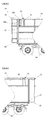
Figure 1 is a side view of a part of the trailer of the invention comprising a tailgate; -
Figure 2 is a side view of the part of the trailer ofFigure 1 viewed from the interior of the trailer; -
Figures 3a to 3d are a series of drawings depicting the operation of the tailgate; -
Figure 4a is a magnified, side view of a hinge assembly which may be used to couple the tailgate to the trailer body; -
Figure 4b is a side view of a hinge assembly ofFigure 4a in which the tailgate has been lifted relative to the trailer body; -
Figure 5a is a magnified, side view of a locking device which may be used to reversibly lock the tailgate to the trailer body; -
Figure 5b is a side view of a locking device ofFigure 5a in which the tailgate has been lifted relative to the trailer body; -
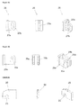
Figure 6a is a side view, a front view, and a perspective view of a slotted plate which may be comprised in the trailer of the invention; -
Figure 6b is a side view, a front view, and a perspective view of support plates which may be comprised in the trailer of the invention; -
Figure 6c is a side view, a front view, and a perspective view of a locking plate which may be comprised in the trailer of the invention; -
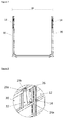
Figure 7 is a front view of the trailer ofFigures 3a to 3d ; and -
Figure 8 is a magnified, perspective view of a part of the sidewall of the trailer of the invention to which the tailgate and ram are mounted. - As illustrated in
Figure 1 , the present invention provides atrailer 10 comprising a trailer body coupled to alockable tailgate 12. The trailer body is coupled to thelockable tailgate 12 by at least onehinge assembly 16 and at least onelocking device 18. Thetrailer 10 further comprises at least oneram 14 disposed between the trailer body andtailgate 12 which is operable to open and close thetailgate 12. Theram 14 may comprisemounts ram 14 to the trailer body andtailgate 12. Thetailgate 12 illustrated inFigure 1 is in a closed configuration and theram 14 is in a contracted state. - Any suitable rams may be used in the
trailer 10 of the invention. In particular, hydraulic cylinders may be used. Advantageously, such cylinders are double-acting hydraulic cylinders. Hydraulic cylinders generally comprise a rod or piston that extends from (and/or retracts into) the cylinders as a results of pumping hydraulic oil into the cylinders. -
Figure 2 provides a cutaway view of the interior of the trailer in which a locking device in the form of a lockingplate 20 located on thetailgate 12 can be seen to engage adowel 22 located on thesidewall 30 of the trailer body. In this configuration, thetailgate 12 is closed and locked. In the illustrated embodiment, thehinge assembly 16 comprises a slottedplate 26 located on thetailgate 12, and apin 28 located on thesidewall 30 of the trailer body. -
Figures 3a to 3d illustrate thetailgate 12 in operation. InFigure 3a , thetailgate 12 is in a closed and locked configuration wherein the lockingplate 20 engages thedowel 22. By "closed" configuration, it is meant that thetailgate 12 is positioned substantially adjacent the trailer body and between thesidewalls 30 of thetrailer 10. However, thetailgate 12 is still free to rotate, or pivot, about thepin 28. By "locked" configuration, it is meant that the lockingplate 20 is engaged with thedowel 22, that is, thedowel 22 is positioned within the slot of the locking plate 20 (Figure 5a ). In this configuration, thetailgate 12 thetailgate 12 is not free to rotate, or pivot, about thepin 28. - The
ram 14 may be operated to lift thetailgate 12 such that the lockingplate 20 no longer engages the dowel 22 (Figures 3b and5b ). This initial lifting of thetailgate 12 is facilitated by thehinge assembly 16 which couples thetailgate 12 to the trailer body. In the illustrated embodiment, the hinge assembly comprises a slottedplate 26 and a pin 28 (shown in greater detail inFigures 4a and 4b ) captured within the slot. The slottedplate 26 is located on thetailgate 12 and thepin 28 is located on thesidewall 30 of thetrailer 10. When thetailgate 12 is lifted by theram 14, the slottedplate 26 moves upwards relative to thepin 28, which may be substantially stationary. Continued extension of theram 14 causes thepin 28 to reach the end of the slot and abut against the slotted plate 26 (Figures 3b and4b ) such that thetailgate 12 can not be lifted any further. The tailgate is still closed but is not locked (Figure 3b ). Further extension of theram 14 causes thetailgate 12 to now rotate (or pivot) about the pin 28 (Figure 3c ). Theram 14 may continue to be operated until it is fully extended (Figure 3d ). In this open configuration, materials may be loaded into, or ejected from, the trailer. - To close the
tailgate 12, theram 14 is retracted in order to reverse the above process. Thetailgate 12 is kept in the lifted position until the slot of the lockingplate 20 and thedowel 22 have aligned (which alignment can be seen inFigure 3b ). Thetailgate 12 is closed but is not locked. Further retraction of theram 14 causes thetailgate 12 to be lowered until the lockingplate 20 re-engages the dowel 22 (Figures 3a and5a ). In the illustrated embodiment, the weight at thetailgate 12 side of the cylinder mounting 24b creates a moment which forces thepin 28 on the trailer body to remain at the lower end of the slot in the slottedplate 26 until the lockingplate 20 and thedowel 22 are substantially aligned for engagement. Retaining thetailgate 12 in the lifted position until the lockingplate 20 and thedowel 22 are aligned is critical to facilitate the locking of thetailgate 12. - In other embodiments, the slotted
plate 26 may be located on thesidewall 30 of thetrailer 10 and thepin 28 is on thetailgate 12. Thus, when thetailgate 12 is lifted by theram 14, thepin 28 moves relative to the substantially stationary slottedplate 26. Further extension of theram 14 causes the tailgate to rotate, or pivot, about the axis of thepin 28. - As illustrated in
Figure 6a , the slottedplate 26 comprises aplate 27a and aslot 27b formed in theplate 27a. Theslot 27b may extend through theplate 27a and thus form an aperture or opening in theplate 27a. Theslot 27b is sized and shaped to receive and retain thepin 28. The slottedplate 26 may be fixed to thetailgate 12 and thepin 28 disposed on the trailer body orsidewall 30 of the trailer body. Alternatively, thepin 28 may be disposed thetailgate 12 and the slottedplate 26 fixed to the trailer body orsidewall 30 of the trailer body. - The
pin 28 may be supported by twosupport plates Figure 6b ) which may be fixed to thetailgate 12, or to the trailer body orsidewall 30 of the trailer body. Thepin 28 may be inserted intoholes support plates support plates plate 26 may be positioned between thesupport plates slot 27b and theholes pin 28 may be inserted intoholes support plates slot 27b of the slottedplate 26 and thus may be reversibly coupled to thesupport plates plate 26. - As illustrated in
Figure 6c , the lockingplate 20 comprises aslot 21 which may be sized and shaped to receive, and reversibly retain, thedowel 22. The lockingplate 20 may be located on thetailgate 12 and thedowel 22 on the trailer body orsidewall 30 of the trailer body. The lockingplate 20 is reversibly engagable with thedowel 22. - Advantageously, the
tailgate 12, theram 14 and/or thehinge assembly 16 may be arranged such that they do not extend beyond, or do not substantially extend beyond the width (W) of the trailer 10 (seeFigure 5 ). Thus, these components are not susceptible to impacting or getting caught in, and damaged by, obstacles (e.g. a gate or gate posts). In certain embodiments, thesidewall 30 of thetrailer 10 comprises a formed space 32 (e.g. a cavity) in which theram 14 may be mounted to thesidewall 30. In this arrangement, theram 14 does not extend beyond the width (W) of thetrailer 10 as illustrated inFigures 7 and 8 . - In further embodiments, the
trailer 10 may be configured to be reversibly attached to a tractor or other towing vehicle. Thus, thetrailer 10 may further comprise a tow bar and/or hitching mechanism (not shown) for attaching thetrailer 10 to the tractor or other towing vehicle which have a corresponding hitching mechanism. Suitable tow bars and hitching mechanisms are well known in the art. The trailer may further comprise two ormore ground wheels 34 suitable for keeping thetrailer 10 spaced apart from the ground. - The
trailer 10 may alternatively be configured to be mounted to a vehicle, such as a flatbed truck. Thus, thetrailer 10 may be configured to be integrally formed with a vehicle, or may be reversibly mountable to the vehicle. - The
trailer 10 may further comprises connection means (not shown) to connect to a power unit operable to provide power to the ram(s) 14. The power unit may be located in a tractor or other vehicle (not shown) and power may be transferred to thetrailer 10 via the connection means. Alternatively, thetrailer 10 may comprise the power unit (not shown). The power unit may comprise an engine for providing hydraulic power to a hydraulic circuit in thetrailer 10, the hydraulic circuit driving the movement of the ram(s) 14. Alternatively, the power unit may be a generator for supplying electrical power, a compressor for supplying pneumatic power, an engine for providing mechanical power, or any combination of these and other known power mechanisms, operable to provide power to suitable rams comprised in thetrailer 10. - The invention is not limited to the embodiments described herein but can be amended or modified without departing from the scope of the present invention as defined by the appended claims.
wherein the ram is operable to open and close the tailgate.
Claims (11)
- A trailer comprising a trailer body coupled to a lockable tailgate,
at least one ram disposed between the trailer body and the tailgate,
wherein the trailer body is coupled to the lockable tailgate by at least one hinge assembly and at least one locking device, and
wherein the ram is operable to open and close the tailgate. - The trailer of Claim 1 wherein the hinge assembly comprises a slotted hinge.
- The trailer of Claim 2 wherein the slotted hinge comprises a first hinge part comprising a pin and a second hinge part comprising a slotted plate having a slot sized and shaped for receiving and retaining the pin, and wherein the slotted plate can undergo translational movement about the pin.
- The trailer of any one of the preceding claims, wherein the locking device comprises a first device part comprising a locking plate and a second device part comprising a dowel, and wherein the locking plate and the dowel are reversibly engagable.
- The trailer of claim 4, when dependent on claim 3, wherein the at least one ram is operable to simultaneously effect translation of the slotted plate relative to the pin and translation of the locking plate relative to the dowel.
- The trailer of Claim 4 or 5 wherein the locking plate comprises a slot that is sized and shaped to receive the dowel.
- The trailer of any of Claims 4 to 6 wherein when the tailgate is in a closed or locked position, the locking plate is disposed in the interior of the trailer.
- The trailer of any one of Claims 3 to 7 wherein the at least one ram is operable to lift the tailgate and rotate, or pivot, the tailgate about the pin.
- The trailer of any one of the preceding claims wherein the trailer body comprises opposing and spaced apart first and second sidewalls, the tailgate being disposed between the first and second sidewalls and coupled to at least one of said sidewalls by the at least one hinge assembly.
- The trailer of any one of the preceding claims comprising a second ram that is operable to rotate, or pivot, the tailgate about the pin.
- The trailer of any one of the preceding claims wherein the at least one ram is disposed between, and mounted to, the trailer body and the tailgate.
Applications Claiming Priority (1)
| Application Number | Priority Date | Filing Date | Title |
|---|---|---|---|
| IES20150009A IES86688B2 (en) | 2015-01-16 | 2015-01-16 | Locking tailgate for a trailer |
Publications (1)
| Publication Number | Publication Date |
|---|---|
| EP3045350A1 true EP3045350A1 (en) | 2016-07-20 |
Family
ID=55177766
Family Applications (1)
| Application Number | Title | Priority Date | Filing Date |
|---|---|---|---|
| EP16151484.9A Withdrawn EP3045350A1 (en) | 2015-01-16 | 2016-01-15 | Locking tailgate for a trailed vehicle |
Country Status (2)
| Country | Link |
|---|---|
| EP (1) | EP3045350A1 (en) |
| IE (1) | IES86688B2 (en) |
Citations (6)
| Publication number | Priority date | Publication date | Assignee | Title |
|---|---|---|---|---|
| FR1389588A (en) * | 1964-01-08 | 1965-02-19 | Sita | Improvement in household waste collection vehicles |
| NL7011169A (en) * | 1969-07-28 | 1971-02-01 | ||
| DE29602985U1 (en) * | 1996-02-20 | 1996-04-18 | B. Strautmann & Söhne GmbH u. Co, 49196 Bad Laer | Unloading flap on an agricultural transport or working device |
| EP0760347A1 (en) * | 1995-08-24 | 1997-03-05 | Kiggen Beheer B.V. | Closing mechanism for a pivoting container door |
| DE102006039673A1 (en) * | 2006-08-24 | 2008-04-03 | Alois Pöttinger Maschinenfabrik Gmbh | Loading truck and forage harvester for introducing harvest, has unloading hatch, which is swiveled around swivel axis and locked in closing position by locking part |
| GB2458756A (en) * | 2008-02-27 | 2009-10-07 | Redrock Engineering Ltd | Trailer door |
-
2015
- 2015-01-16 IE IES20150009A patent/IES86688B2/en not_active IP Right Cessation
-
2016
- 2016-01-15 EP EP16151484.9A patent/EP3045350A1/en not_active Withdrawn
Patent Citations (6)
| Publication number | Priority date | Publication date | Assignee | Title |
|---|---|---|---|---|
| FR1389588A (en) * | 1964-01-08 | 1965-02-19 | Sita | Improvement in household waste collection vehicles |
| NL7011169A (en) * | 1969-07-28 | 1971-02-01 | ||
| EP0760347A1 (en) * | 1995-08-24 | 1997-03-05 | Kiggen Beheer B.V. | Closing mechanism for a pivoting container door |
| DE29602985U1 (en) * | 1996-02-20 | 1996-04-18 | B. Strautmann & Söhne GmbH u. Co, 49196 Bad Laer | Unloading flap on an agricultural transport or working device |
| DE102006039673A1 (en) * | 2006-08-24 | 2008-04-03 | Alois Pöttinger Maschinenfabrik Gmbh | Loading truck and forage harvester for introducing harvest, has unloading hatch, which is swiveled around swivel axis and locked in closing position by locking part |
| GB2458756A (en) * | 2008-02-27 | 2009-10-07 | Redrock Engineering Ltd | Trailer door |
Also Published As
| Publication number | Publication date |
|---|---|
| IES86688B2 (en) | 2016-08-10 |
| IES20150009A2 (en) | 2016-07-27 |
Similar Documents
| Publication | Publication Date | Title |
|---|---|---|
| MX2011004532A (en) | Trailer for transporting freight containers and method of use. | |
| EP1661755B1 (en) | Load carrying vehicle, in particular skip transport vehicle | |
| US4929028A (en) | Lift hitch | |
| EP1867499B1 (en) | Tow-hook arrangement and method for coupling an object to be towed to a mobile working machine | |
| CH702380A2 (en) | Towing. | |
| SK90599A3 (en) | Powered road vehicle comprising a replaceable rear body mounting | |
| KR20250056785A (en) | A locking assembly | |
| US3410577A (en) | Coupling device | |
| EP3546326A1 (en) | Device and method for increasing the traction of a pulling machine | |
| IES20150009A2 (en) | Locking tailgate for a trailer | |
| DE102010045085B4 (en) | Length adjustable drawbar, truck trailer hoist and door for a box body of a truck trailer hoist | |
| EP4046873A1 (en) | Holder device for a motor vehicle | |
| US4258930A (en) | Hitching device with safety lock | |
| DE69214509T2 (en) | Gooseneck-like separable articulated connection between a carrier and towing vehicle and an equipment carrier semi-trailer | |
| EP3045348A1 (en) | Ejector and compactor system | |
| EP4001006B1 (en) | Device for locking a tailgate of a container | |
| DE202015106895U1 (en) | dump truck | |
| DE202015106219U1 (en) | Container display device, in particular silo display device, for a commercial vehicle and commercial vehicle with such a container display device | |
| DE102004041432B4 (en) | Door locking device | |
| DE102014202476A1 (en) | demountable | |
| DE9317545U1 (en) | Swiveling side wall of a transport vehicle | |
| EP2368766B1 (en) | Transport box | |
| DE102008060734B3 (en) | Loading support for a semi-trailer | |
| EP1950068A2 (en) | Trailer sheeting system | |
| EP4414251A1 (en) | Internal loader with variable underrun protection |
Legal Events
| Date | Code | Title | Description |
|---|---|---|---|
| PUAI | Public reference made under article 153(3) epc to a published international application that has entered the european phase |
Free format text: ORIGINAL CODE: 0009012 |
|
| AK | Designated contracting states |
Kind code of ref document: A1 Designated state(s): AL AT BE BG CH CY CZ DE DK EE ES FI FR GB GR HR HU IE IS IT LI LT LU LV MC MK MT NL NO PL PT RO RS SE SI SK SM TR |
|
| AX | Request for extension of the european patent |
Extension state: BA ME |
|
| STAA | Information on the status of an ep patent application or granted ep patent |
Free format text: STATUS: THE APPLICATION IS DEEMED TO BE WITHDRAWN |
|
| 18D | Application deemed to be withdrawn |
Effective date: 20170121 |