EP3045350A1 - Verriegelbare heckklappe für ein schleppfahrzeug - Google Patents
Verriegelbare heckklappe für ein schleppfahrzeug Download PDFInfo
- Publication number
- EP3045350A1 EP3045350A1 EP16151484.9A EP16151484A EP3045350A1 EP 3045350 A1 EP3045350 A1 EP 3045350A1 EP 16151484 A EP16151484 A EP 16151484A EP 3045350 A1 EP3045350 A1 EP 3045350A1
- Authority
- EP
- European Patent Office
- Prior art keywords
- trailer
- tailgate
- ram
- pin
- optionally
- Prior art date
- Legal status (The legal status is an assumption and is not a legal conclusion. Google has not performed a legal analysis and makes no representation as to the accuracy of the status listed.)
- Withdrawn
Links
Images


Classifications
-
- B—PERFORMING OPERATIONS; TRANSPORTING
- B60—VEHICLES IN GENERAL
- B60P—VEHICLES ADAPTED FOR LOAD TRANSPORTATION OR TO TRANSPORT, TO CARRY, OR TO COMPRISE SPECIAL LOADS OR OBJECTS
- B60P1/00—Vehicles predominantly for transporting loads and modified to facilitate loading, consolidating the load, or unloading
- B60P1/04—Vehicles predominantly for transporting loads and modified to facilitate loading, consolidating the load, or unloading with a tipping movement of load-transporting element
- B60P1/26—Means for controlling movement of tailboards or sideboards
Definitions
- This invention relates to a trailer having a lockable tailgate.
- Tailgates form part of trailed vehicles such as trailers and are typically located at the rear of the trailer. In a closed and locked configuration, the tailgate is arranged to retain material to be transported in the trailer. When the material is to be loaded into or ejected from the trailer, the tailgate is unlocked and then opened.
- a conventional locking tailgate requires the operator to exit the cabin of a tractor or other vehicle that is towing the trailer and manually unlock the tailgate, return to the cabin and empty the contents of the trailer via whatever method that trailer uses (tipping / ejector plate / walking floor). The operator then relies on gravity and/or momentum due to the weight and position of the tailgate to close it again, and the operator must then exit the cab and lock the tailgate. This process can sometimes be unsafe as some trailer loads can cause pressure to act on the tailgate and, once unlocked, the tailgate can swing open with force potentially causing injury to the operator.
- Hydraulically controlled tailgates are known in the art and are used to overcome some of the drawbacks of manually operated tailgates.
- tailgates have themselves a number of drawbacks.
- the components of the hydraulically controlled tailgates generally overlap or project beyond the sides of the main trailer body. Due to the positioning of the trailer tailgate at the rear of the trailer, it can also be difficult for an operator to have an adequate view of the trailer and tailgate. This can result in parts of a tailgate assembly impacting or getting caught in obstacles (e.g. a gate or gate posts) that the pulling vehicle and trailer body would otherwise pass without problem. Also, this can cause damage to the tailgate and/or to the obstacles themselves.
- obstacles e.g. a gate or gate posts
- the present invention had been devised with a view to mitigating these problems.
- the present invention provides a trailer comprising
- the trailer of the invention offers the operator of said trailer greater control of the tailgate compared to that of a conventional tailgate.
- the trailer may be operated remotely, for example, from the cabin of a tractor or other vehicle to which the trailer is coupled. Therefore, the trailer of the invention removes risks associated with the manual operation of the trailer since the operator does not have to leave the safety of the tractor or vehicle as the unlocking, opening, closing and re-locking of the tailgate may all be controlled remotely.
- the trailer body comprises opposing and spaced apart first and second sidewalls.
- the tailgate is disposed between the first and second sidewalls.
- the tailgate is disposed between, and at the ends of, the first and second sidewalls.
- the tailgate is substantially planar.
- the tailgate is coupled to at least one of said sidewalls by at least one hinge assembly.
- the tailgate is coupled to each sidewall by at least one hinge assembly.
- the tailgate comprises first and second ends wherein the first end of the tailgate is coupled to the first sidewall by at least one hinge assembly, and the second end is coupled to the second sidewall by at least one hinge assembly.
- the hinge assembly comprises first and second hinge parts that are respectively complementary.
- the hinge assembly comprises first and second hinge parts which are arranged to rotate, optionally pivot, relative to each other.
- the first hinge part is located on the trailer body and the second hinge part is located on the tailgate.
- the first hinge part is located on a sidewall of the trailer body and the second hinge part is located on the tailgate.
- the first hinge part is located on the tailgate and the second hinge part is located on the trailer body.
- the first hinge part is located on the tailgate and the second hinge part is located on a sidewall of the trailer body.
- the hinge assembly comprises a slotted hinge.
- the slotted hinge comprises a first hinge part comprising a pin and a second hinge part comprising a slotted plate having a slot sized and shaped for receiving and retaining the pin.
- the slotted plate can undergo translational movement about the pin, and can rotate, or pivot, about the pin. Seen another way, that pin can move along the slot of the slotted plate and can rotate, or pivot, within the slot.
- the slotted plate is located on the tailgate and the pin is located on the trailer body.
- the pin is located on the tailgate and the slotted plate is located on the trailer body.
- the slotted plate is located on the tailgate and the pin is located on a sidewall of the trailer body.
- the pin is located on the tailgate and the slotted plate is located on a sidewall of the trailer body.
- the locking device comprises first and second device parts that are respectively complementary.
- the locking device comprises first and second device parts that are reversibly engagable between a locked position and an unlocked position.
- the first device part is located on the tailgate and the second device part is located on the trailer body.
- the first device part is located on the tailgate and the second device part is located on a sidewall of the trailer body.
- the locking device comprises a first device part comprising a locking plate and a second device part comprising a dowel.
- the locking plate and the dowel are reversibly engagable.
- the locking plate comprises a slot that is sized and shaped to receive the dowel.
- the locking plate comprises a slot that is sized and shaped to reversibly receive the dowel.
- locking plate is located on the tailgate and the dowel is located on the trailer body.
- the locking plate is located on the tailgate and the dowel is located on a sidewall of the trailer body.
- the locking plate is disposed in the interior of the trailer.
- the trailer comprises at least one ram that is operable to lift the tailgate.
- the trailer comprises at least one ram that is operable to lift the tailgate and rotate, or pivot, the tailgate about the pin.
- the trailer comprises a ram that is operable to lift the tailgate and a further ram that is operable to rotate, or pivot, the tailgate about the pin.
- the ram is a double-acting ram.
- the ram is a hydraulic cylinder, optionally a double-acting hydraulic cylinder.
- the ram is disposed between, and mounted to, the trailer body and the tailgate.
- the ram is disposed between, and mounted to, a sidewall of the trailer body and the tailgate.
- the tailgate Retraction of the tailgate causes the tailgate to rotate, or pivot, about the pin in the opposite direction. Further retraction of the ram causes the tailgate to be lowered relative to the trailer body, thus causing the first hinge part to be lowered relative to the second hinge part, and the first device part to be lowered relative to the second device part causing the first and second device parts to re-engage.
- the ram is attached to the trailer body, optionally to a sidewall, via a mount, optionally a hydraulic cylinder mount.
- the ram is attached to the tailgate via a mount, optionally a hydraulic cylinder mount.
- the trailer is configured to be reversibly attached to a tractor or other towing vehicle.
- the trailer is configured to be towed by a tractor or other towing vehicle.
- the trailer is configured to be mounted to a vehicle.
- the trailer may be configured to be integrally formed with a vehicle, or may be reversibly mountable to the vehicle.
- the trailer comprises connection means to connect to a power unit operable to provide power to the rams comprised in the trailer.
- the power unit is located in a tractor or other towing vehicle to which the trailer may be reversibly attached, or located in a vehicle to which the trailer may be mounted.
- the trailer comprises a power unit operable to provide power to the rams comprised in the trailer.
- the power unit comprises an engine for providing power via a hydraulic circuit comprised in the trailer, the hydraulic circuit driving the movement of the hydraulic rams of the trailers.
- the power unit is a generator for supplying electrical power, a compressor for supplying pneumatic power, an engine for providing mechanical power, or any combination of these and other known power mechanisms, operable to provide power to the rams comprised in the trailer.
- the present invention provides a trailer 10 comprising a trailer body coupled to a lockable tailgate 12.
- the trailer body is coupled to the lockable tailgate 12 by at least one hinge assembly 16 and at least one locking device 18.
- the trailer 10 further comprises at least one ram 14 disposed between the trailer body and tailgate 12 which is operable to open and close the tailgate 12.
- the ram 14 may comprise mounts 24a, 24b for attaching the ram 14 to the trailer body and tailgate 12.
- the tailgate 12 illustrated in Figure 1 is in a closed configuration and the ram 14 is in a contracted state.
- Hydraulic cylinders generally comprise a rod or piston that extends from (and/or retracts into) the cylinders as a results of pumping hydraulic oil into the cylinders.
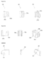
- Figure 2 provides a cutaway view of the interior of the trailer in which a locking device in the form of a locking plate 20 located on the tailgate 12 can be seen to engage a dowel 22 located on the sidewall 30 of the trailer body.
- the tailgate 12 is closed and locked.
- the hinge assembly 16 comprises a slotted plate 26 located on the tailgate 12, and a pin 28 located on the sidewall 30 of the trailer body.
- FIGs 3a to 3d illustrate the tailgate 12 in operation.
- the tailgate 12 is in a closed and locked configuration wherein the locking plate 20 engages the dowel 22.
- closed configuration it is meant that the tailgate 12 is positioned substantially adjacent the trailer body and between the sidewalls 30 of the trailer 10. However, the tailgate 12 is still free to rotate, or pivot, about the pin 28.
- locked configuration it is meant that the locking plate 20 is engaged with the dowel 22, that is, the dowel 22 is positioned within the slot of the locking plate 20 ( Figure 5a ). In this configuration, the tailgate 12 the tailgate 12 is not free to rotate, or pivot, about the pin 28.
- the ram 14 may be operated to lift the tailgate 12 such that the locking plate 20 no longer engages the dowel 22 ( Figures 3b and 5b ).
- This initial lifting of the tailgate 12 is facilitated by the hinge assembly 16 which couples the tailgate 12 to the trailer body.
- the hinge assembly comprises a slotted plate 26 and a pin 28 (shown in greater detail in Figures 4a and 4b ) captured within the slot.
- the slotted plate 26 is located on the tailgate 12 and the pin 28 is located on the sidewall 30 of the trailer 10.
- the slotted plate 26 moves upwards relative to the pin 28, which may be substantially stationary.
- the ram 14 is retracted in order to reverse the above process.
- the tailgate 12 is kept in the lifted position until the slot of the locking plate 20 and the dowel 22 have aligned (which alignment can be seen in Figure 3b ).
- the tailgate 12 is closed but is not locked. Further retraction of the ram 14 causes the tailgate 12 to be lowered until the locking plate 20 re-engages the dowel 22 ( Figures 3a and 5a ).
- the weight at the tailgate 12 side of the cylinder mounting 24b creates a moment which forces the pin 28 on the trailer body to remain at the lower end of the slot in the slotted plate 26 until the locking plate 20 and the dowel 22 are substantially aligned for engagement. Retaining the tailgate 12 in the lifted position until the locking plate 20 and the dowel 22 are aligned is critical to facilitate the locking of the tailgate 12.
- the slotted plate 26 may be located on the sidewall 30 of the trailer 10 and the pin 28 is on the tailgate 12.
- the pin 28 moves relative to the substantially stationary slotted plate 26. Further extension of the ram 14 causes the tailgate to rotate, or pivot, about the axis of the pin 28.
- the slotted plate 26 comprises a plate 27a and a slot 27b formed in the plate 27a.
- the slot 27b may extend through the plate 27a and thus form an aperture or opening in the plate 27a.
- the slot 27b is sized and shaped to receive and retain the pin 28.
- the slotted plate 26 may be fixed to the tailgate 12 and the pin 28 disposed on the trailer body or sidewall 30 of the trailer body.
- the pin 28 may be disposed the tailgate 12 and the slotted plate 26 fixed to the trailer body or sidewall 30 of the trailer body.
- the pin 28 may be supported by two support plates 29a,29b ( Figure 6b ) which may be fixed to the tailgate 12, or to the trailer body or sidewall 30 of the trailer body.
- the pin 28 may be inserted into holes 31 a,31 b of the support plates 29a,29b and thus may be reversibly coupled to the support plates 29a,29b.
- the slotted plate 26 may be positioned between the support plates 29a,29b such that the slot 27b and the holes 31a,31b are substantially aligned.
- the pin 28 may be inserted into holes 31 a,31 b of the support plates 29a,29b and the slot 27b of the slotted plate 26 and thus may be reversibly coupled to the support plates 29a,29b and the slotted plate 26.
- the locking plate 20 comprises a slot 21 which may be sized and shaped to receive, and reversibly retain, the dowel 22.
- the locking plate 20 may be located on the tailgate 12 and the dowel 22 on the trailer body or sidewall 30 of the trailer body.
- the locking plate 20 is reversibly engagable with the dowel 22.
- the tailgate 12, the ram 14 and/or the hinge assembly 16 may be arranged such that they do not extend beyond, or do not substantially extend beyond the width (W) of the trailer 10 (see Figure 5 ).
- these components are not susceptible to impacting or getting caught in, and damaged by, obstacles (e.g. a gate or gate posts).
- the sidewall 30 of the trailer 10 comprises a formed space 32 (e.g. a cavity) in which the ram 14 may be mounted to the sidewall 30. In this arrangement, the ram 14 does not extend beyond the width (W) of the trailer 10 as illustrated in Figures 7 and 8 .
- the trailer 10 may be configured to be reversibly attached to a tractor or other towing vehicle.
- the trailer 10 may further comprise a tow bar and/or hitching mechanism (not shown) for attaching the trailer 10 to the tractor or other towing vehicle which have a corresponding hitching mechanism.
- Suitable tow bars and hitching mechanisms are well known in the art.
- the trailer may further comprise two or more ground wheels 34 suitable for keeping the trailer 10 spaced apart from the ground.
- the trailer 10 may alternatively be configured to be mounted to a vehicle, such as a flatbed truck.
- the trailer 10 may be configured to be integrally formed with a vehicle, or may be reversibly mountable to the vehicle.
- the trailer 10 may further comprises connection means (not shown) to connect to a power unit operable to provide power to the ram(s) 14.
- the power unit may be located in a tractor or other vehicle (not shown) and power may be transferred to the trailer 10 via the connection means.
- the trailer 10 may comprise the power unit (not shown).
- the power unit may comprise an engine for providing hydraulic power to a hydraulic circuit in the trailer 10, the hydraulic circuit driving the movement of the ram(s) 14.
- the power unit may be a generator for supplying electrical power, a compressor for supplying pneumatic power, an engine for providing mechanical power, or any combination of these and other known power mechanisms, operable to provide power to suitable rams comprised in the trailer 10.
Landscapes
- Engineering & Computer Science (AREA)
- Transportation (AREA)
- Mechanical Engineering (AREA)
- Lock And Its Accessories (AREA)
Applications Claiming Priority (1)
| Application Number | Priority Date | Filing Date | Title |
|---|---|---|---|
| IES20150009A IES86688B2 (en) | 2015-01-16 | 2015-01-16 | Locking tailgate for a trailer |
Publications (1)
| Publication Number | Publication Date |
|---|---|
| EP3045350A1 true EP3045350A1 (de) | 2016-07-20 |
Family
ID=55177766
Family Applications (1)
| Application Number | Title | Priority Date | Filing Date |
|---|---|---|---|
| EP16151484.9A Withdrawn EP3045350A1 (de) | 2015-01-16 | 2016-01-15 | Verriegelbare heckklappe für ein schleppfahrzeug |
Country Status (2)
| Country | Link |
|---|---|
| EP (1) | EP3045350A1 (de) |
| IE (1) | IES86688B2 (de) |
Citations (6)
| Publication number | Priority date | Publication date | Assignee | Title |
|---|---|---|---|---|
| FR1389588A (fr) * | 1964-01-08 | 1965-02-19 | Sita | Perfectionnement aux bennes de collecte des ordures ménagères |
| NL7011169A (de) * | 1969-07-28 | 1971-02-01 | ||
| DE29602985U1 (de) * | 1996-02-20 | 1996-04-18 | B. Strautmann & Söhne GmbH u. Co, 49196 Bad Laer | Entladeklappe an einem landwirtschaftlichen Transport- oder Arbeitsgerät |
| EP0760347A1 (de) * | 1995-08-24 | 1997-03-05 | Kiggen Beheer B.V. | Verschluss für Behälterklappe |
| DE102006039673A1 (de) * | 2006-08-24 | 2008-04-03 | Alois Pöttinger Maschinenfabrik Gmbh | Lade- und/oder Häckselwagen |
| GB2458756A (en) * | 2008-02-27 | 2009-10-07 | Redrock Engineering Ltd | Trailer door |
-
2015
- 2015-01-16 IE IES20150009A patent/IES86688B2/en unknown
-
2016
- 2016-01-15 EP EP16151484.9A patent/EP3045350A1/de not_active Withdrawn
Patent Citations (6)
| Publication number | Priority date | Publication date | Assignee | Title |
|---|---|---|---|---|
| FR1389588A (fr) * | 1964-01-08 | 1965-02-19 | Sita | Perfectionnement aux bennes de collecte des ordures ménagères |
| NL7011169A (de) * | 1969-07-28 | 1971-02-01 | ||
| EP0760347A1 (de) * | 1995-08-24 | 1997-03-05 | Kiggen Beheer B.V. | Verschluss für Behälterklappe |
| DE29602985U1 (de) * | 1996-02-20 | 1996-04-18 | B. Strautmann & Söhne GmbH u. Co, 49196 Bad Laer | Entladeklappe an einem landwirtschaftlichen Transport- oder Arbeitsgerät |
| DE102006039673A1 (de) * | 2006-08-24 | 2008-04-03 | Alois Pöttinger Maschinenfabrik Gmbh | Lade- und/oder Häckselwagen |
| GB2458756A (en) * | 2008-02-27 | 2009-10-07 | Redrock Engineering Ltd | Trailer door |
Also Published As
| Publication number | Publication date |
|---|---|
| IES20150009A2 (en) | 2016-07-27 |
| IES86688B2 (en) | 2016-08-10 |
Similar Documents
| Publication | Publication Date | Title |
|---|---|---|
| EP1661755B1 (de) | Lastentransportfahrzeug, insbesondere Absetzkipper | |
| MX2011004532A (es) | Remolque para transportar contenedores de carga y metodo de uso. | |
| EP3061636A1 (de) | Heckklappe mit laderaumerweiterer für nutzkraftfahrzeug und kraftfahrzeug | |
| US4929028A (en) | Lift hitch | |
| CH702380A2 (de) | Anhängerzug. | |
| EP1867499B1 (de) | Abschlepphaken und Verfahren zum Ankuppeln eines von einer mobilen Arbeitsmaschine zu schleppenden Gegenstandes | |
| DE69800282T2 (de) | Motorfahrzeug mit variablem aufbau an der rückseite | |
| EP3546326A1 (de) | Vorrichtung und verfahren zur erhöhung der traktion einer zugmaschine | |
| US3410577A (en) | Coupling device | |
| DE102013201000A1 (de) | Faltplatte und Spriegel für eine Schiebeverdeckstruktur eines Lastwagens | |
| EP3045350A1 (de) | Verriegelbare heckklappe für ein schleppfahrzeug | |
| DE102010045085B4 (de) | Längenveränderliche Deichsel, LKW-Anhängerzug und Tür für einen Kofferaufbau eines LKW-Anhängerzuges | |
| US4258930A (en) | Hitching device with safety lock | |
| EP3045348A1 (de) | Ejektor und kompaktorsystem | |
| DE19957499A1 (de) | Durchladbarer Gliederzug, insbesondere zum Transport von Lebensmitteln | |
| DE202015106895U1 (de) | Kippfahrzeug | |
| DE202021102572U1 (de) | Verladevorrichtung und Transport- und Verladeanordnung | |
| EP4001006B1 (de) | Vorrichtung zur verriegelung einer behälterklappe | |
| EP2368766B1 (de) | Transportbox | |
| DE9317545U1 (de) | Schwenkbare Bordwand eines Transportfahrzeugs | |
| DE102008060734B3 (de) | Ladestütze für einen Sattelauflieger | |
| KR20070015650A (ko) | 트레일러용 토잉바 | |
| DE202015106219U1 (de) | Behälteraufsteller-Vorrichtung, insbesondere Siloaufsteller-Vorrichtung, für ein Nutzfahrzeug sowie Nutzfahrzeug mit derartiger Behälteraufsteller-Vorrichtung | |
| WO2016042147A1 (de) | Lastkraftwagen mit einer hubeinrichtung für container | |
| EP1950068A2 (de) | Abdeckungssystem für Anhänger |
Legal Events
| Date | Code | Title | Description |
|---|---|---|---|
| PUAI | Public reference made under article 153(3) epc to a published international application that has entered the european phase |
Free format text: ORIGINAL CODE: 0009012 |
|
| AK | Designated contracting states |
Kind code of ref document: A1 Designated state(s): AL AT BE BG CH CY CZ DE DK EE ES FI FR GB GR HR HU IE IS IT LI LT LU LV MC MK MT NL NO PL PT RO RS SE SI SK SM TR |
|
| AX | Request for extension of the european patent |
Extension state: BA ME |
|
| STAA | Information on the status of an ep patent application or granted ep patent |
Free format text: STATUS: THE APPLICATION IS DEEMED TO BE WITHDRAWN |
|
| 18D | Application deemed to be withdrawn |
Effective date: 20170121 |