EP3044539B1 - Roughness measuring instrument for use in a machine tool and method for measuring roughness in a machine tool - Google Patents
Roughness measuring instrument for use in a machine tool and method for measuring roughness in a machine tool Download PDFInfo
- Publication number
- EP3044539B1 EP3044539B1 EP14777536.5A EP14777536A EP3044539B1 EP 3044539 B1 EP3044539 B1 EP 3044539B1 EP 14777536 A EP14777536 A EP 14777536A EP 3044539 B1 EP3044539 B1 EP 3044539B1
- Authority
- EP
- European Patent Office
- Prior art keywords
- roughness
- measurement
- probe
- insert
- workpiece
- Prior art date
- Legal status (The legal status is an assumption and is not a legal conclusion. Google has not performed a legal analysis and makes no representation as to the accuracy of the status listed.)
- Revoked
Links
- 238000000034 method Methods 0.000 title claims description 27
- 238000012360 testing method Methods 0.000 claims description 63
- 238000005259 measurement Methods 0.000 claims description 62
- 238000004439 roughness measurement Methods 0.000 claims description 60
- 241001422033 Thestylus Species 0.000 claims description 31
- 230000005540 biological transmission Effects 0.000 claims description 18
- 238000012545 processing Methods 0.000 claims description 15
- 239000000463 material Substances 0.000 claims description 12
- 238000003754 machining Methods 0.000 claims description 7
- 238000009499 grossing Methods 0.000 claims description 5
- 238000013459 approach Methods 0.000 claims 2
- FGUUSXIOTUKUDN-IBGZPJMESA-N C1(=CC=CC=C1)N1C2=C(NC([C@H](C1)NC=1OC(=NN=1)C1=CC=CC=C1)=O)C=CC=C2 Chemical compound C1(=CC=CC=C1)N1C2=C(NC([C@H](C1)NC=1OC(=NN=1)C1=CC=CC=C1)=O)C=CC=C2 FGUUSXIOTUKUDN-IBGZPJMESA-N 0.000 claims 1
- 230000003213 activating effect Effects 0.000 claims 1
- 230000000284 resting effect Effects 0.000 claims 1
- 239000000523 sample Substances 0.000 description 154
- 229910003460 diamond Inorganic materials 0.000 description 11
- 239000010432 diamond Substances 0.000 description 11
- 230000003746 surface roughness Effects 0.000 description 9
- 238000004519 manufacturing process Methods 0.000 description 8
- 229910000971 Silver steel Inorganic materials 0.000 description 7
- 229910001750 ruby Inorganic materials 0.000 description 7
- 239000010979 ruby Substances 0.000 description 7
- 229910000639 Spring steel Inorganic materials 0.000 description 6
- 230000007423 decrease Effects 0.000 description 6
- 230000004888 barrier function Effects 0.000 description 5
- 229910018072 Al 2 O 3 Inorganic materials 0.000 description 4
- 238000012935 Averaging Methods 0.000 description 4
- 238000011156 evaluation Methods 0.000 description 4
- UONOETXJSWQNOL-UHFFFAOYSA-N tungsten carbide Chemical compound [W+]#[C-] UONOETXJSWQNOL-UHFFFAOYSA-N 0.000 description 4
- 229910052782 aluminium Inorganic materials 0.000 description 3
- XAGFODPZIPBFFR-UHFFFAOYSA-N aluminium Chemical compound [Al] XAGFODPZIPBFFR-UHFFFAOYSA-N 0.000 description 3
- 238000005452 bending Methods 0.000 description 3
- 239000000919 ceramic Substances 0.000 description 3
- 230000008859 change Effects 0.000 description 3
- 230000001939 inductive effect Effects 0.000 description 3
- 230000007246 mechanism Effects 0.000 description 3
- 238000012544 monitoring process Methods 0.000 description 3
- 230000002093 peripheral effect Effects 0.000 description 3
- 230000008569 process Effects 0.000 description 3
- 230000008878 coupling Effects 0.000 description 2
- 238000010168 coupling process Methods 0.000 description 2
- 238000005859 coupling reaction Methods 0.000 description 2
- 238000001514 detection method Methods 0.000 description 2
- 230000000694 effects Effects 0.000 description 2
- 230000005484 gravity Effects 0.000 description 2
- 230000001965 increasing effect Effects 0.000 description 2
- 230000000737 periodic effect Effects 0.000 description 2
- 238000003860 storage Methods 0.000 description 2
- 238000011144 upstream manufacturing Methods 0.000 description 2
- 229910000906 Bronze Inorganic materials 0.000 description 1
- 229920000049 Carbon (fiber) Polymers 0.000 description 1
- 239000004952 Polyamide Substances 0.000 description 1
- 229910052581 Si3N4 Inorganic materials 0.000 description 1
- XUIMIQQOPSSXEZ-UHFFFAOYSA-N Silicon Chemical compound [Si] XUIMIQQOPSSXEZ-UHFFFAOYSA-N 0.000 description 1
- 229910000831 Steel Inorganic materials 0.000 description 1
- 238000005299 abrasion Methods 0.000 description 1
- 239000000853 adhesive Substances 0.000 description 1
- 230000001070 adhesive effect Effects 0.000 description 1
- REYFJDPCWQRWAA-UHFFFAOYSA-N antazoline Chemical compound N=1CCNC=1CN(C=1C=CC=CC=1)CC1=CC=CC=C1 REYFJDPCWQRWAA-UHFFFAOYSA-N 0.000 description 1
- 230000008901 benefit Effects 0.000 description 1
- 239000010974 bronze Substances 0.000 description 1
- 238000004364 calculation method Methods 0.000 description 1
- 239000004917 carbon fiber Substances 0.000 description 1
- 229910010293 ceramic material Inorganic materials 0.000 description 1
- 238000012512 characterization method Methods 0.000 description 1
- 238000004891 communication Methods 0.000 description 1
- 238000004590 computer program Methods 0.000 description 1
- 238000010276 construction Methods 0.000 description 1
- KUNSUQLRTQLHQQ-UHFFFAOYSA-N copper tin Chemical compound [Cu].[Sn] KUNSUQLRTQLHQQ-UHFFFAOYSA-N 0.000 description 1
- 238000005520 cutting process Methods 0.000 description 1
- 230000001419 dependent effect Effects 0.000 description 1
- 238000009826 distribution Methods 0.000 description 1
- 238000005516 engineering process Methods 0.000 description 1
- 238000001914 filtration Methods 0.000 description 1
- 239000002783 friction material Substances 0.000 description 1
- 238000007689 inspection Methods 0.000 description 1
- 230000003993 interaction Effects 0.000 description 1
- 239000000314 lubricant Substances 0.000 description 1
- 229910052751 metal Inorganic materials 0.000 description 1
- 239000002184 metal Substances 0.000 description 1
- 238000003801 milling Methods 0.000 description 1
- 238000012986 modification Methods 0.000 description 1
- 230000004048 modification Effects 0.000 description 1
- -1 non-magnetic Substances 0.000 description 1
- RVTZCBVAJQQJTK-UHFFFAOYSA-N oxygen(2-);zirconium(4+) Chemical compound [O-2].[O-2].[Zr+4] RVTZCBVAJQQJTK-UHFFFAOYSA-N 0.000 description 1
- 230000010363 phase shift Effects 0.000 description 1
- 229920002647 polyamide Polymers 0.000 description 1
- 238000000275 quality assurance Methods 0.000 description 1
- 230000009467 reduction Effects 0.000 description 1
- 238000012552 review Methods 0.000 description 1
- 229910052710 silicon Inorganic materials 0.000 description 1
- 239000010703 silicon Substances 0.000 description 1
- HQVNEWCFYHHQES-UHFFFAOYSA-N silicon nitride Chemical compound N12[Si]34N5[Si]62N3[Si]51N64 HQVNEWCFYHHQES-UHFFFAOYSA-N 0.000 description 1
- 229910001220 stainless steel Inorganic materials 0.000 description 1
- 239000010935 stainless steel Substances 0.000 description 1
- 239000010959 steel Substances 0.000 description 1
- 239000011009 synthetic ruby Substances 0.000 description 1
- 230000008719 thickening Effects 0.000 description 1
- 238000012546 transfer Methods 0.000 description 1
- 230000007704 transition Effects 0.000 description 1
- 238000007514 turning Methods 0.000 description 1
- 238000012795 verification Methods 0.000 description 1
- 239000002699 waste material Substances 0.000 description 1
- 229910001928 zirconium oxide Inorganic materials 0.000 description 1
Images


Classifications
-
- G—PHYSICS
- G01—MEASURING; TESTING
- G01B—MEASURING LENGTH, THICKNESS OR SIMILAR LINEAR DIMENSIONS; MEASURING ANGLES; MEASURING AREAS; MEASURING IRREGULARITIES OF SURFACES OR CONTOURS
- G01B11/00—Measuring arrangements characterised by the use of optical techniques
- G01B11/30—Measuring arrangements characterised by the use of optical techniques for measuring roughness or irregularity of surfaces
- G01B11/303—Measuring arrangements characterised by the use of optical techniques for measuring roughness or irregularity of surfaces using photoelectric detection means
-
- G—PHYSICS
- G01—MEASURING; TESTING
- G01B—MEASURING LENGTH, THICKNESS OR SIMILAR LINEAR DIMENSIONS; MEASURING ANGLES; MEASURING AREAS; MEASURING IRREGULARITIES OF SURFACES OR CONTOURS
- G01B5/00—Measuring arrangements characterised by the use of mechanical techniques
- G01B5/28—Measuring arrangements characterised by the use of mechanical techniques for measuring roughness or irregularity of surfaces
Definitions
- a significant demand on its surface is that it is manufactured inexpensively in view of the function to be performed by the surface of the workpiece (e.g., bearing surface, conductivity, visible surface, adhesive strength, friction, seal).
- the properties of the surface for example low friction, large contact surface, defined minimum roughness, sharp points, low abrasion
- Real workpiece surfaces deviate from their ideal shape (target surface). These differences are divided into several categories.
- the actual surface is divided into waves of different wavelengths. In this case, the wavelength decreases with the order of shape deviations (1st order: shape deviation, 2nd order: waviness, 3rd order: roughness - grooves, 4th order: roughness - grooves, scales, crests).
- tactile measuring devices are often used.
- the surface is scanned with a diamond tip to determine the roughness.
- This device usually has an inductive converter.
- a probe with the diamond tip moves perpendicular to the groove direction over the surface of the workpiece and the vertical stroke of the probe tip is converted into an inductive transducer in an electrical signal.
- This measurement signal of the primary profile is usually read using an analog-to-digital converter in an evaluation computer.
- Such a surface inspection apparatus operates unidirectionally, i.
- the probe with the diamond tip can only be pulled in a single direction relative to the workpiece surface.
- This surface testing device has three components, namely buttons, feed unit and evaluation unit with display and documentation.
- the button converts the vertical movement of the stylus tip into an electrical signal.
- the button has a high-precision mounted probe tip and the inductive converter.
- the button can be supplemented by a skid.
- a skid For the large variety of geometries to be measured, such as surfaces, shafts, bores, involutes, etc., there are a variety of different probe shapes. Basically, a distinction is made between single-touch buttons, two-button buttons and reference level buttons. Push-buttons with skids are mainly used in hand-held devices. The skid follows the waviness. It acts as a high-pass filter and ignores the macroscopic shape of the profile. Sliding callipers do not give exact information about shape and waviness.
- buttons are mainly used in the workshop area.
- the reference plane probe system measures against a reference surface and thus provides an almost unadulterated image of the primary profile.
- diamond cones are used with a rounded tip. Nominal values for the probe tip are the tip radius (eg 2 ⁇ m, 5 ⁇ m or 10 ⁇ m) and the cone angle of the diamond cone, ie its tip, with z. B. 60 ° or 90 °.
- the feed unit guides the probe continuously and at constant speed over the workpiece surface.
- feed devices with and without reference plane and rotary feed devices.
- Most gauges have a feed unit with built-in reference plane. They allow the use of buttons with and without skid. Feeders without reference plane allow only the use of Gleitkufentastern. Only feeders with built-in reference plane in conjunction with a button without skid allow the exact detection of shape, waviness and roughness. The accuracy of the shape measurement depends primarily on the accuracy of the reference plane.
- a rotary feeder rotates a cylindrical sample under the stationary button. Concentricity of the workpiece can be eliminated by the use of sliding skid buttons.
- this type of surface inspector is problematic in use in the production of workpieces in that the workpiece is to be unclamped from the spindle of the machine tool and inserted into the surface inspector to measure its roughness.
- This is disadvantageous because re-clamping the workpiece in the machine tool usually leads to the loss of dimensional stability during further processing in relation to the previously executed processing steps. Therefore, usually the surface finish of a workpiece is checked only after completion of processing in the machine tool. A rework is then possible only in exceptional cases. For example, if the required surface finish is not met, the workpiece is rejected.
- the assessment of the surface roughness is therefore previously possible only as a downstream control step or as a manual operation on the clamped workpiece. Despite wear or micro-breakouts on the cutting edge, although the production dimension in some processing steps can still be within the tolerance or the intervention limits; On the other hand, the surface roughness may already be outside the specification.
- the missing link for the process-oriented monitoring of the surface quality is a device for measuring the roughness, which is used fully automatically in the machine tool. Neither the manual internal nor the classic external roughness measurement are such practical solutions.
- Another multidirectional probe for performing contour measurements is off DE 102 62 188 B4 known, which has a receptacle for removable Tastriche.
- the document also describes different styli with ball-shaped or disc-shaped probes.
- probes are described with several hemispherical and disc-shaped Taststellgeometrien, which are used depending on the Antastraum.
- a device for roughness measurement is off DE 102 06 146 A1 known.
- the document discloses a vibration detection system with stylus construction comprising a stylus configured as an inclined cylinder and having a disc-shaped contact point.
- US 2002/0 059 041 A1 a device and a method for contour and roughness measurement in a machine tool.
- the device can be mounted instead of the tool in a machine tool.
- a method and / or a device for increasing the productivity and for keeping to the highest possible quality requirements shall be provided.
- the invention provides a multidirectional roughness measuring insert according to independent claim 1 and a roughness measuring method according to independent claim 10.
- a multidirectional roughness measuring insert for determining a surface characteristic for the roughness of a surface is proposed with a multidirectional measuring mechanism, with a support body on which a Tastrich technique is arranged for receiving a stylus, an analog sensor, the deflections of the support body in for the roughness of a surface of a workpiece converts characteristic measurement signals to a stylus to be coupled to the support body comprising a rod-shaped shaft and a probe attached to the shaft, the probe comprising at least a portion of at least a portion of the rod-shaped shaft substantially rotationally symmetrical
- the test specimen is, or wherein the probe is at least a portion of a substantially rotationally symmetric test body, which is arranged at a distal end of at least a portion of the rod-shaped shaft.
- the substantially rotationally symmetric test specimen has a double cone shape or a double truncated cone shape.
- a region of the largest diameter (equator) of the specimen is formed as a contact point to a surface to be measured of a workpiece, wherein the contact point is formed by two double cone or double frustum lateral surfaces, and the contact point is rounded in the region of the largest diameter of the specimen.
- This arrangement allows the use of an analog measuring probe in a spindle in a machine tool instead of a tool.
- a probe with an analog measuring function is combined with one of the styli described here.
- the probe is an analog scanning probe, which is used for the roughness measurement in the spindle of the machine tool and the measured data or in a probe located in the probe calculator roughness values or the like.
- An analog scanning probe supplies a measurement signal representing an increase and decrease of a deflection of the probe tip of the measuring insert. This is to be seen in contrast to a digitally scanning probe, which provides only an on-off or off-on switching signal when the stylus is deflected by a predetermined amount from its rest position.
- a variant of such a probe works with a e.g. rotationally symmetrical measuring device, in which an analog measuring signal is generated from the shadowing of a miniature light barrier.
- an analog measuring signal is generated from the shadowing of a miniature light barrier.
- the beginning of the shadowing of the light barrier is detected at a deflection of the stylus by a predetermined amount from its rest position.
- the analog measurement signal can also reflect the rise and fall of shading, which arise when the probe tip of the measuring insert is more or less deflected. This generates an analogue measurement signal.
- the variants of the roughness measuring insert presented here are multidirectional insofar as due to the rotationally symmetric measuring mechanism in conjunction with the specifically designed feeler pins a probing of a surface of a workpiece can take place from any direction.
- the multidirectional roughness measurement inserts for example, retract into a hole or a milled into a workpiece recess with the stylus and then laterally to the wall of the hole or the milled cut in any orientation of the roughness meter insert.
- This is not possible with conventional roughness measuring instruments, since the diamond cone tip can be measured only in the direction of its cone tip.
- the machine tool With the multidirectional roughness measuring inserts, which are to be used in a spindle of a machine tool, the machine tool is used as a feed device. In addition, the machine tool also provides the necessary reference plane.
- the multidirectional roughness measuring insert is configured with a housing in which an annular support bearing is formed, which defines an X, Y-bearing plane and a normal to this central axis Z of the roughness measuring insert.
- the roughness measuring insert has a support body on which a stylus recording is centrally located for receiving a stylus.
- the roughness measuring insert further has a transmission member which is guided displaceably in the housing along the central axis Z in order to implement any deflections of the support body from its rest position into rectilinear movements.
- the transmission element in its rest position is aligned at least in sections with the central axis Z.
- the roughness measuring insert also has an analog sensor which converts the rectilinear movements of the transmission element into measuring signals characteristic of the roughness of a surface of a workpiece. Coupled to the transmission member is a pin-shaped member or stylus comprising the rod-shaped shaft and the probe attached to the shaft.
- the probe head of the multidirectional roughness measuring insert comprises at least a portion of a test piece which is essentially rotationally symmetrical with respect to the central axis Z.
- the analog sensor may be a light barrier of the type described above.
- the rod-shaped shaft may be coupled directly or indirectly in rectilinear extension to the transmission member, or angled at about 0 ° to about 40 °, directly or indirectly coupled to the transmission member.
- the rod-shaped shaft can be approximately 20 ° to about 30 °, preferably about 25 ° angled connected to the transmission member or with the support body. If a surface with such an arrangement can not be reached, a bending of the shaft by 90 ° is also possible.
- the contact point can be formed at least by sections of two double-cone or double-frustum lateral surfaces, wherein the contact point is rounded off in the area of the largest diameter of the test body.
- the contact point of the test piece of the multidirectional roughness measuring insert may have a radius of about 0.4 mm to about 3 mm, respective cone angles of about 30 ° to about 70 ° in the region of the largest diameter or circumference or radius. It is true that at the largest circumference, ie at the equator of the test specimen, this can not have a circular shape but also an elliptical or other cross-sectional shape deviating from the circular shape.
- the contact point of the test specimen of the multidirectional roughness measuring insert can have an edge radius of about 5 ⁇ m to about 50 ⁇ m in the area of the largest diameter.
- the curvature of the contact point of the test specimen may have a constant value, or the curvature may change along a curved region of the contact point of the specimen.
- the latter variant encompasses embodiments in which the edge at the largest diameter or the largest circumference, that is to say at the equator of the test specimen, has no edge rounding to be described with a radius, but instead has an e.g. has parabolic or a spline-curved, or other edge shape.
- the contact point of the test specimen may have a double conical shape or a double frustum shape with a radius in the region of the largest diameter of about 1.5 mm to about 5 mm or from about 0.4 mm to about 3 mm, an edge radius of about 5 ⁇ m to about 50 microns and respective cone angles of about 30 ° to about 130 °.
- the two cone angles can be about 90 °, the radius in the area of the largest diameter about 1.5 mm and the edge radius about 40 ⁇ m.
- the two cone angles can be about 120 °, the radius in the region of the largest diameter about 1.1 mm and the edge radius about 10 microns.
- the two cone angles can be about 60 °, the radius in the region of the largest diameter about 1.5 mm and the edge radius about 20 ⁇ m.
- the contact point of the test specimen of the multidirectional roughness measuring insert can have a feed direction which is oriented at least approximately in the axial direction of the largest radius.
- the multidirectional roughness measuring insert can be configured with a processing unit coupled to the analog sensor in order to determine at least one characteristic that is characteristic for the roughness of a surface from the measuring signals, wherein the processing unit is either arranged in or separated from the housing of the roughness measuring insert.
- a multidirectional roughness measuring insert of the type described here has a stylus that physically contacts a surface to be measured and a transducer for converting the movement of the stylus into an electrical signal that is then further processed.
- the part of the stylus that is in contact with the surface is the probe.
- the probe head is designed with a profile shape adapted to the measuring task integrated in the production process of the workpiece. Due to their finite shape, some profiles of the probe lead to a greater effect or better interaction with the surface to be measured than others. The size and the shape or the profile of the stylus must be carefully selected. These features affect the information obtained during the roughness measurement.
- Pins and probes are slender shafts with contact tips or heads to measure the roughness of surfaces on workpieces being machined in a machine tool.
- the stylus has a cylindrical rod or slender cone with a probe rotationally symmetric to the central longitudinal axis of the stylus.
- a pen is a narrow elongated shaft similar to the shape of a ballpoint pen. The pen can be slightly convex, so it can be easily grasped.
- the probes for roughness measurements usually consist of ruby, carbide or ceramic materials. Stylus pins or heads touch the workpiece to perform roughness measurements.
- the stylus consists of a single piece of material, but some styli or heads consist of a ruby or diamond insert that is soldered, pressed or glued into the head. The material of the probe can affect the measurement.
- the probe can z.
- Example be a Al 2 O 3 ruby body of synthetic monocrystalline ruby, a Siliziumnitridève of press-hard Si 3 N 4 , a Zirkonoxid stresses sintered ZrO 2 , a hollow body of white aluminum Al 2 O 3 sintered ceramic, a disc of silver steel, a simple silver steel disc Silver steel, a silver steel cylinder disc of silver steel, a ruby-ended synthetic ruby cylinder, a tungsten carbide cylinder ending in a tungsten carbide disc, a silver steel disc of silver steel having a peripheral edge angle of 30 ° to 120 ° with a rounded peripheral edge of tungsten carbide or other material ,
- the rod or shank may be made of different materials including non-magnetic, stainless steel, ceramic and carbon fibers.
- Disc-shaped probes are thin sections of a double cone containing its equator.
- a large disc diameter reduces the impact or pressure on the surface of the workpiece, the roughness of which must be checked.
- a relatively slim shaft provides flexibility in accessing specific points of measurement.
- the multidirectional roughness measuring insert can, in addition to a roughness measurement, furthermore make it possible to determine a characteristic variable characteristic of the contour of a surface.
- a variant of the roughness measuring insert makes it possible to carry out both a contour measurement and a roughness measurement with the same tool insert. An exchange of the tool insert for carrying out the different measurements, which would require additional cycle time in the case of a process-related application, is not necessary when using such a variant of the roughness measuring insert.
- the multidirectional roughness measuring insert can have a stylus with a first probe for roughness measurement and a second probe for contour measurement.
- the first probe as the variants of the roughness measuring insert described above, at least a portion of a substantially rotationally symmetrical and substantially disc-shaped first specimen.
- the second probe may be at least a portion of a substantially spherical or ellipsoid second probe.
- the second probe can be arranged at a distal end of at least a portion of the shaft of the stylus.
- the second specimen may be substantially rotationally symmetrical to that portion of the shank. The contact point of the second probe can correspond to the lateral surface of the portion of the second specimen.
- the first probe and the second probe can be arranged at a distal end of at least a portion of the shaft of the stylus.
- the first test body and / or the second test body may be rotationally symmetrical to the portion of the shaft.
- the axes of rotation of the first and second test specimens may not correspond to the axis of rotation of the portion of the stem.
- the stylus may include a probe comprising the first probe and the second probe, wherein the probe may be disposed at the distal end of a portion of the stem.
- the second probe in a first region of the test head of the first probe and be arranged in a second region of the probe, the second probe.
- the first region and the second region may be on two oppositely disposed and / or adjacent sides of the probe.
- the test head can be provided in one piece or in several pieces.
- the probe has a substantially spherical or ellipsoidal shape except for the first region in which the first probe is formed, and except for a region where the probe communicates with the portion of the stem.
- the shape of the probe thus corresponds to the shape of the second probe.
- the probe may have a missing sphere or ellipsoidal portion in the first region, such that a spherical or ellipsoidal surface is formed on the probe.
- the first probe head protrude centrally and / or orthogonally from the circular or elliptical surface.
- the test head in the first region may have a portion in the form of a cylindrical body on which the first probe is provided.
- the cylindrical body may be rotationally symmetrical to the first specimen, wherein the radius of the cylindrical body is preferably smaller than the radius in the region of the largest diameter of the first specimen.
- the stylus may comprise the first probe arranged at a distal end of a first portion of the stylus and the second probe disposed at a distal end of a second portion of the stylus.
- the first portion comprising the first probe is formed as an axial extension of the shaft of the stylus.
- the second section having the second probe can be arranged proximally in front of the first section on the shaft.
- the second portion may be orthogonal to the first portion.
- first portion and the second portion may be provided at the distal end of the shaft and orthogonal thereto.
- first portion and the second portion may be provided on opposite sides of the shaft.
- longitudinal axes of the first portion and the second portion may be orthogonal or parallel to each other. An embodiment in which correspond to the longitudinal axes of the first portion and the second portion is also conceivable.
- the multidirectional roughness measuring insert can be moved by a machine tool into a measuring space relative to the measuring surface of the workpiece.
- the contacting roughness measuring insert detects a surface of the workpiece upon contact therewith.
- the multidirectional roughness measuring insert emits corresponding measurement data to its processing unit.
- the processing unit may include a computer program.
- the determination of the ripple and roughness profile and the calculation of the parameters such as arithmetic mean roughness, square mean roughness, maximum single roughness, roughness depth, average roughness depth, mean groove depth, mean groove width, wave depth, profile depth etc. are carried out by digital filtering.
- a stylus (not independently claimed) for use in a multidirectional roughness metering insert has a rod-shaped shaft and a probe attached to the shaft, the probe being at least a portion of a test piece substantially rotationally symmetric to at least a portion of the rod-shaped shaft, or at least the probe a portion of a substantially rotationally symmetric specimen disposed at a distal end of at least a portion of the rod-shaped shaft.
- the substantially rotationally symmetric test specimen has a double cone shape or a double truncated cone shape.
- a region of the largest diameter (equator) of the specimen is formed as a contact point to a surface to be measured of a workpiece, wherein the contact point is formed by two double cone or double frustum lateral surfaces, and the contact point is rounded in the region of the largest diameter of the specimen.
- the step of probing the probe to the surface to be measured by starting the roughness measurement insert in a machine tool relative to the measured surface of a workpiece can be done.
- the step of traversing a predetermined measuring path along a predetermined measuring direction may comprise either specifying a distance to be swept by the probe or predetermining a time duration during which the probe covers the measuring distance, and the predetermined time Measuring direction can include any direction to be selected along the surface to be measured.
- the step of evaluating the measurement signals-in a processor in the roughness measurement insert or downstream-can store and link the measurement signals recorded by the analog sensor to at least one of the surface roughness metrics: arithmetic mean roughness, averaged roughness, quadratic Average roughness, maximum single roughness, surface roughness, average depth of smoothness, mean depth of ridge, average groove width, wave depth, profile depth. Furthermore, information about shape deviations 1. u. 2nd order.
- the step of evaluating the measurement signals recorded by means of the analog sensor also includes processing of the measurement signals by means of a profile filter, since otherwise the ripple falsifies the roughness too much.
- a profile filter eg. A digital phase-corrected Gaussian filter separates the unfiltered primary profile (P-profile) into roughness (R-profile) and ripple
- the reference line or center line in the roughness profile is the line corresponding to the long-wave profile components which are detected and suppressed by the Gaussian filter.
- the Gaussian filter When using the Gaussian filter, the distortions of the profile in the vertical direction, due to sudden change in the profile height, are reduced. The phase shift in the horizontal direction is completely eliminated.
- the weighted arithmetic mean of the ordinate heights is calculated at each point using the Gaussian filter. So that points at the beginning and end of the measuring section can also be weighted correctly, the scanning distance must be longer than the total measuring distance for the filter to swing in and out.
- the usual precedence and follow-up distances are each half the limiting wavelength.
- the cut-off wavelength of a profile filter is the wavelength at which the filter reduces the amplitude of a sine wave to half. It can thus be understood as a measure of the boundary between roughness and waviness.
- the cutoff wavelength defines the transition of the roughness to even shorter wavelengths and the cutoff wavelength limits the ripple over longer wavelengths.
- the cut-off wavelengths are to be selected according to the average groove width and for aperiodic profiles according to the roughness value to be measured.
- the total measuring distance of a measurement is always five times the cut-off wavelength.
- the tactile distance is six times.
- the cut-off wavelength decreases, the amplitude of the filtered roughness profile decreases and that of the ripple profile decreases. Thus smaller roughness values are also measured at shorter cut-off wavelengths.
- Roughness parameters are calculated from the filtered profile. Therefore, the cutoff wavelength used is relevant, especially in comparison measurements.
- the primary profile, the waviness and the roughness are differentiated.
- the value of a profile parameter is obtained by averaging the individual results of individual measurement sections directly one behind the other.
- the arithmetic mean roughness is the arithmetic mean of the values of the ordinate values of the roughness profile within the single measurement section. It represents the average deviation of the profile from the middle line.
- the average roughness can not distinguish between peaks and grooves, nor can it recognize different profile shapes. Its definition is based on a strong averaging.
- the root mean square roughness is the root mean square of the profile deviation. It is defined in a similar way to the average roughness, but it is more sensitive to individual peaks and ridges.
- the average roughness depth is the sum of the height of the largest profile peak and the depth of the largest profile valley within a single measuring section. Usually averaged roughness results from averaging the results of five individual measuring sections. Overall, averaged roughness is more sensitive to the change in surface textures than the average roughness.
- the maximum single roughness is the largest single rooted.
- the roughness depth is the vertical difference between the lowest depth and the highest peak within the total measuring distance. The following roughness parameters help with the "horizontal" characterization of a profile.
- the definition of the mean smoothing depth is almost identical to the average roughness depth.
- the filtered profile is divided into five equal slots that correspond to the cut-off wavelength. In contrast to the determination of the average surface roughness, the distance from the center line to the highest peak is taken in each segment.
- the average smoothing depth is the arithmetic mean of these five values.
- the mean groove depth is formed analogously to the mean smoothing depth. Ridge depths are used instead of peak heights. For storage areas, grooves serve as lubricant pockets, for example. Tips are again undesirable because they would increase friction and wear. In the case of press dressings, too, the average smoothing depth is frequently used, since press dressings require the largest possible contact area.
- the mean groove width is the arithmetic mean of the widths of the profile elements of the roughness profile within a single measuring section. Here, a profile element is a profile elevation with an adjacent recess. The mean groove width results from averaging the results of five individual measuring sections. It is used in periodic profiles to select the cut-off wavelength of the filter.
- the wave depth shows the maximum depth of the filtered profile after the roughness has been filtered out.
- the tread depth is the distance between two parallel lines that inject the unfiltered surface profile.
- the lines have the shape of the ideal profile (eg straight line, circle).
- the roughness measuring method described here is also characterized in that the above method steps are performed in a machine tool, wherein the roughness measuring insert is used instead of a tool in a spindle of the machine tool and outputs the measuring signals and or the measured variable to a machine control of the machine tool become.
- the method steps can be executed after and / or before processing steps by means of at least one tool on the workpiece in the machine tool.
- the multidirectional roughness measuring insert can be oriented along a predetermined measuring direction in the step of running a pre-determined measuring path such that the contact point of the test body has a feed direction which is oriented at least approximately in the axial direction of the larger radius of the test body, and the tangent direction of the larger Radius is aligned at least approximately parallel to a groove direction of the workpiece to be measured.
- the roughness measuring inserts presented here for the measurement of workpiece surfaces can be integrated directly into the machining process. Due to the process-integrated monitoring of the workpiece surfaces, the manufacturing processes are much more efficient than before.
- a possible reduction of downtime of the machine tool is achieved by eliminating tedious manual roughness measurements.
- the cost of scrap through immediate rework is minimized. Tools can be driven to their wear limit and do not need to be replaced preventively.
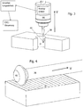
- the in Fig. 1 and Fig. 2 in the rest position or in the deflected position shown multidirectional roughness measuring insert M has a substantially cylindrical housing, which consists of a proximal, in the drawings upper housing part 12 with a projection 14 on the one hand and a distal, in the drawings lower housing part 16 with a radially inwardly projecting Housing flange 18 on the other hand is composed.
- annular support bearing 20 is formed in the form of an annular groove having a radially inner, convex truncated cone surface 22 and a radially outer, concave truncated cone surface 24; these two frustoconical surfaces are arranged approximately at right angles to each other in the axial cross section in the probe shown.
- the radially outer, concave truncated cone surface 24 is steeper, for example, inclined at 75 ° to the plane of the distal end face of the housing flange 18. In any case, it is useful if the frusto-conical surfaces 22 and 24 are coated with or made of friction-reducing material.
- a mushroom-shaped support body 26 is arranged, on which an annular abutment 28 is formed.
- the anvil 28 has an approximately semicircular or composed of several arc sections with different radii cross section and can be referred to in each case as a torus.
- the support body 26 takes in Fig. 1 a rest position in which the anvil 28, the support bearing 20 along a flat circular contact line 30 - and nowhere - touches. This circular contact line lies on the convex, radially inner frustoconical surface 22 of the annular support bearing 20.
- the annular abutment 28 From the concave, radially outer frustoconical surface 24 of the support bearing, however, the annular abutment 28 has a minimum distance of preferably a few microns (2 - 10 microns), as long as the support body 26 assumes its rest position. This distance can decrease at one point to the amount zero, ie that the support body 26 assumes a slightly eccentric rest position in which the anvil 28 touches the radially outer, concave frusto-conical surface 24 of the support bearing 20 at one point.
- the plane of the contact line 30 is referred to below as the storage level X, Y; orthonormal, ie at right angles to it, the hereinafter referred to as the central axis Z axis of the probe M, ie its housing 12, 14.
- the support body 26 has its own longitudinal axis T, in the rest position and in purely axial deflection of the support body 26 with the central axis Z practically coincides.
- the annular abutment 28 contacts the radially inner, convex truncated cone surface 22 of the annular support bearing 20 only in a radially inner contact point 32.
- the abutment 28 contacts the radially outer, concave frustoconical surface 24 of the support bearing 20 in a radially outer point of contact 34th ,
- the supporting body 26 of the roughness measuring insert M is equipped with a central stylus holder 36 which extends in the distal direction along the longitudinal axis T and in the direction of the longitudinal axis T on the support body 26 of the roughness measuring insert M is displaceable.
- the stylus receptacle 36 is intended to receive a replaceable stylus 38 carrying a stylus 40.
- the projection 14 of the proximal housing part 14 has an outgoing from the interior of the housing 10 axial, that is concentric to the central axis Z bore 48 into the radially an analog sensor 50, and this diametrically opposite, projecting an emitter 52 for a measuring beam.
- the emitter 52 is a light source which, together with the sensor 50, for example, a PSD (Engl. Position sensitive detector) forms a miniature light barrier with an analog output signal.
- PSD Electronics Position sensitive detector
- PSD components use the effect of the lateral distribution of the generated photocurrent.
- a PSD refers to a device based on Silicon PIN diode technology that allows the measurement of the position of the integral center of gravity of an incident light signal.
- a PSD converts the energy of, for example, a light spot imaged thereon into a continuous electrical signal corresponding to the position of the center of gravity of that spot.
- the position of a direction is obtained from the ratio of two output currents. But there are also other sensor arrangements can be used.
- any deflection of the probe 40, and thus also the Tastrich technique 36, from its rest position is communicated to the sensor 50 by a transmission member 54, which is a slender, straight bending bar and preferably made of drawn spring steel wire of circular cross section with a diameter of 0.5 to 1 , 2 mm.
- a transmission member 54 which is a slender, straight bending bar and preferably made of drawn spring steel wire of circular cross section with a diameter of 0.5 to 1 , 2 mm.
- the measuring beam from the emitter 52 is shaded further or less far from the rest position, as shown in FIG Fig. 2 is illustrated. This is evaluated in a not further illustrated electronics.
- a spring steel wire of 0.8 mm diameter has proven itself; for especially small roughness fair inserts M is coming but also spring steel wire considerably smaller diameter, for example, 0.2 mm in question.
- the transmission member 54 extends in rest position straight along the central axis Z of the roughness measuring insert M; its distal end 56 is fixed centrally to the stylus holder 36. Near its proximal end 58, the transmission member 54 is guided in a guide bushing 60.
- the guide bush 60 may be compared to the material of the transmission member 54 - drawn spring steel wire - low friction material, such. As polyamide or sintered bronze.
- the guide bush 60 is a commercially available hardened drill bush with a ground bore has proven particularly useful.
- the transfer member 54 is coated in the section adjacent to its proximal end 58 with friction-reducing material.
- the proximal end 58 of the transmission member 54 projects beyond the proximal end of the guide bush 60 and extends into the center of the light beam emitted by the emitter 52 in the direction of the sensor 50.
- the transmission member 54 is here a spring steel wire whose usable length for bending with the distance between the distal, in the drawings so lower end of the guide bushing 60 and the proximal, ie upper end face of the support body 26 matches.
- a rigid pin can be used, which is mounted oscillating.
- the formed on the distal housing part 16 annular support bearing 20 and the support body 26 formed on the annular abutment 28 is formed in a variant of a planer toothing.
- the support body 26 is prevented in its rest position and in all radial deflections of the probe carried by him 40 from rotating about its longitudinal axis T.
- One of the two cooperating teeth is rounded in a variant arcuate.
- the teeth can roll off each other when tilting the support body 26.
- FIG. 1 shown pin-shaped component, a stylus, has a rod-shaped shaft or pin 38 and attached to the pin 38 probe 40.
- the rod-shaped shaft 38 is made in this variant of hard metal. It is of course possible to use different materials for the rod-shaped shaft 38 and the probe 40.
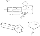
- the probe 40 has a double-conical shape and may be made of ruby or diamond, which are adhered to the rod-shaped shaft 38. The probe 40 may, for.
- Bicone probe 40 is unitary, but may be thought of as being formed of two symmetrical truncated cones, with a small radius R4 at both ends of probe 40 and a largest radius R2 at the equator of probe 40.
- the small radius R4 at the proximal portion PP of the probe 40 is identical to the small radius R4 at the distal portion DP of the probe 40. Since the two top surfaces of the double cone probe 40 are oriented parallel to each other, the probe 40 has a generally Barrel or disc shape.
- the probe 40 has a ratio of the small radius R4 to the radius R2 at the equator of 0.5 to 1.
- the annular edge is rounded with a radius R3.
- the double cone probe 40 has a cone angle KW of about 55 °.
- the probe 40 may also generally have an asymmetrical bicone shape. This means that the equator (i.e., the portion of the largest diameter or radius of the probe 40) is not in the center of the double cone.
- the measuring force of a roughness measuring insert presented here is generally higher than that of a conventional stylus instrument.
- a disc-shaped test specimen is used instead of the usual test cone with a rounded tip.
- a test specimen geometry that is optimal for the measuring task is defined.
- the feed direction V is generally in the axial direction of the largest radius in the roughness measurement insert presented here.
- the tangent direction of the largest radius is aligned in the examples parallel to the groove direction of the workpiece. In this arrangement, the peripheral line of the test piece or probe 40, the valley of the machining grooves (see, eg Fig. 4 ) to reach.
- Fig. 3 illustrates how to use the multidirectional roughness measuring insert M for measuring the roughness in a hole in a workpiece O.
- Fig. 4 illustrates how to use the multidirectional roughness measuring insert M for measuring the roughness in a surface on a workpiece O.
- the Fig. 6 to 10 show variants of probes 40 with different shapes and dimensions.
- the contact point of the test specimen has a bicone shape or a double truncated shape with a radius in the region of the largest diameter of about 0.4 mm to about 3 mm, an edge radius of about 5 ⁇ m to about 50 ⁇ m and the respective cone angle has about 30 ° to about 130 ° ,
- FIG. 10 This shows in particular Fig. 10 an arrangement in which the probe 40 is formed in the axial extension of the rod-shaped shaft 38. Again, a feed direction V is provided normal to the largest radius.
- the two cone angles can be about 90 °, the radius in the area of the largest diameter about 1.5 mm and the edge radius about 40 ⁇ m. In another variant, the two cone angles can be about 120 °, the radius in the region of the largest diameter about 1.1 mm and the edge radius about 10 microns. In a further variant, the two cone angles can be about 60 °, the radius in the region of the largest diameter about 1.5 mm and the edge radius about 20 ⁇ m.
- the feed direction is indicated in each case in one direction. However, it is also possible to move the roughness measurement inserts presented here in the opposite direction for roughness measurement.
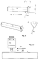
- Fig. 11 Another variant of a roughness measuring insert is illustrated.
- the measuring mechanism is modified and simplified so that it can only be used along an axis A for roughness measurement.
- This roughness measuring insert has a housing 100, from which a slim sensor receptacle 110 projects with a unidirectionally deflectable analog measuring module 120.
- a processing unit having an evaluation electronics unit 130 for the measurement signals detected by the measurement module and characterizing the roughness of a surface of a workpiece.
- a wireless infrared or radio module 140 for data transmission of the determined roughness data to a CNC control or an interface upstream of the CNC controller.
- the unidirectionally deflectable analog measurement module 120 has a pivot arm 122 which is connected via a spring joint 124 in the form of a substantially rectangular spring plate in the shaft with a pivoting of about plus / minus 0.15 - 0.35, z. B. 0.25 mm is added.
- the spring joint 124 secures in the form of a leaf spring, that the pivot arm can not migrate laterally.
- one side of the spring plate is fastened with two screws 125 on a sensor base, which in turn is fastened in the slim sensor receptacle 110.
- the other side of the spring plate is screwed to the pivot arm 122 with two screws.
- a pin 126 is arranged, which projects into a measuring beam of a light barrier 128 and this, depending on the degree of deflection of the pivot arm, shaded more or less.
- the basic position of the pin 126 in the rest position of the pivot arm 122 can be adjusted by a screw 127, which defines the angular position of the pivot arm 122 in the rest position relative to the slim sensor receptacle 110.
- a probe 40 of the type described above, in particular the Fig. 10 but also one of the other variants is possible, which is to be brought into contact with a surface of a workpiece to measure their roughness.
- the roughness measuring insert is inserted into the spindle of a machine tool and, controlled by the CNC control of the machine tool, moved over the surface of the workpiece.
- This roughness measuring insert can be flanged radially or axially on the spindle of the machine tool.
- the interface 150 upstream of the CNC control graphically displays the results. This can be used for logging and evaluation. Thus, surfaces that are not in order can be recognized as close to the process. By measuring in the original clamping in the machine tool, there is the simple possibility of reworking. In this way a rejection of workpieces due to surface roughness can be reduced to a minimum.
- the measuring module can achieve a measuring force of about 50 mN with this embodiment. This is achieved by the low spring force and the low moving masses. With lower measuring forces compared to the multidirectional measuring unit, the probe can also be designed with smaller radii without the Hertzian pressure becoming too high. Thus, the roughness measurement hereby is at least almost standard.
- Fig. 12a to 12c show a first variant and Fig. 13a to 13c show a second variant of a stylus with a first probe 40 for roughness measurement and a second probe 41 for contour measurement.
- the stylus has a cylindrical shaft 38, at the lower end in the axial direction of a test head 4 is arranged, which comprises the first probe 40 and the second probe 41. Except for a region in which the first probe 40 is formed, and except for a region in which the test head 4 is in communication with the shaft 38, the test head 4 has a nearly spherical shape.
- Fig. 12a and Fig. 13a show a side view of the first probe 40 of the respective stylus, in which the first probe 40 is disposed on the left side of the probe 4.
- FIG. 12b and 13b a front view of the first probe 41 of the respective stylus, in which the stylus relative to the representation in Fig. 12a respectively.
- Fig. 13a is rotated at an angle of about 90 ° about the shaft 38 to the right.
- Fig. 12c and 13c Furthermore, a spatial representation of the respective styli is shown.
- the first probe 40 is formed as a portion of a first test piece having a double truncated shape.
- the first specimen is rotationally symmetrical to an axis of symmetry which is parallel to the longitudinal axis of the cylindrical shaft T.
- the contact point of the first probe 40 is in the range of the largest radius of the first specimen, the feed direction for roughness measurement normal? is provided to the contact point.
- the second probe 41 is a portion of a spherical second test piece, which is rotationally symmetrical to the longitudinal axis of the shaft T and the spherical portion of the test head 4 corresponds.
- the contact point of the second probe head 41 thus corresponds in part to the lateral surface of the test head 4 and preferably extends from a region which is formed on the opposite side to the first probe, to a region at the lower, distal end of the test head 4th
- Fig. 12a to 12c is a first variant of the stylus illustrated.
- the first test body is rotationally symmetrical to the axis of rotation R, which is parallel to the longitudinal axis of the shaft T, but this does not correspond.
- the radius in the region of the largest diameter of the first specimen ie, the distance between the contact point of the first probe 40 and the axis of rotation R, corresponds to almost the sum of the radius of the second specimen and the distance between the longitudinal axis of the shaft T and the axis of rotation R.
- the probe 4 has a portion of a cylindrical body, which is also rotationally symmetrical to the axis of rotation T and at which the first probe 40 is formed centrally on the lateral surface.
- the radius of the cylindrical body is smaller than the radius in the region of the largest diameter of the first specimen.
- the shape of the test head 4 corresponds to the intersection of the first test body and the second test body.
- a second variant of a stylus is illustrated in which the test head 4 in the region of the first probe 40 has a missing ball portion and thus has a circular surface.
- the first probe 40 is formed in the axial extension of a rod-shaped pin, which protrudes centrally from the circular surface of the probe 4 and is arranged orthogonal to this.
- the spherical test specimens 41 may be made in accordance with Fig. 12 u. 13 can be used as a standard stylus for probing different vector directions.
- Fig. 14a to 14c show variants of roughness measurement inserts with a first probe 40 for roughness measurement and a second probe 41 for contour measurement, which are arranged at different portions of a stylus.
- a first embodiment of such a roughness measuring insert is illustrated. Shown is a roughness measuring insert with a housing 100, (term “housing” is already used in the description of the measuring device from page 7 and is not appropriate here 100 marked part actually represents only a thickening of the shaft) on which in the axial direction a cylindrical shaft is arranged, which extends in the direction of the distal end of the roughness measuring insert. At the distal end of the shaft, a cylindrical first portion 38 and a cylindrical second portion 39 are further arranged. The first probe 40 is formed at the distal end of the cylindrical first portion 38, whereas the second probe 41 is formed at the distal end of the cylindrical second portion 39. In Fig.
- the cylindrical second portion 39 is designed as an axial extension of the shaft. Proximally in front of the cylindrical second portion 39, the first cylindrical portion 38 is disposed orthogonal thereto. In this case, the first probe 40 is formed in the axial extension of the cylindrical first portion 38.
- the first probe 40 is a portion of a first test specimen having a double-frustum shape in which the contact point is in the region of the largest radius. The feed direction for roughness measurement is normal to the largest radius of the first specimen or parallel to the shaft.
- the second probe 41 corresponds, except for a region in which the cylindrical second portion 39 is connected to the second probe 41, a spherical second specimen whose radius is greater than the radius of the cylindrical second portion 39.
- the second probe 41 is included rotationally symmetrical to the cylindrical second section 39.
- Fig. 14b a variant of the roughness measuring insert is illustrated, in which the cylindrical second portion 39, at the distal end of the second probe head 41 is formed, is also provided orthogonal to the shaft.
- the cylindrical first portion 38 and the cylindrical second portion 39 are disposed on opposite sides of the shaft such that they correspond in their longitudinal axis.
- Fig. 14c shows a further embodiment in which the cylindrical second portion 39 is arranged with the second probe 41 orthogonal to the shaft, whereas the cylindrical first portion 38 is formed with the first probe 40 in axial extension of the shaft.
- the first probe 40 has a Doppelkegelstumpfgestalt and is rotationally symmetrical to the cylindrical first portion 38, wherein the contact point is in the region of the largest radius of the first probe 40.
- the feed direction for roughness measurement is therefore, according to the previous embodiments, provided parallel to the longitudinal axis of the shaft.
Description
Hier wird ein Verfahren zur Messung der Rauheit eines in einer Werkzeugmaschine bearbeiteten Werkstücks beschrieben. Außerdem werden die entsprechenden Vorrichtungskomponenten wie der spezifisch dazu eingerichtete Messtaster und die spezifisch dazu eingerichtete Tastspitze erläutert. Details hierzu sind in den Ansprüchen definiert; aber auch die Beschreibung und die Zeichnung enthalten relevante Angaben zur Struktur und zur Funktionsweise sowie zu Varianten des Verfahrens und den Vorrichtungskomponenten.Here, a method for measuring the roughness of a workpiece machined in a machine tool will be described. In addition, the corresponding device components, such as the probe specifically designed for this purpose and the probe tip specifically designed for it, are explained. Details are defined in the claims; but also the description and the drawing contain relevant information on the structure and operation as well as variants of the method and the device components.
Bei einem in einer Werkzeugmaschine bearbeiteten Werkstück ist eine maßgebliche Forderung an dessen Oberfläche, dass diese angesichts der von der Oberfläche des Werkstücks zu erfüllenden Funktion (z.B. Lagerfläche, Leitfähigkeit, Sichtfläche, Haftfestigkeit, Reibung, Dichtung) kostengünstig hergestellt ist. Dazu sind die Eigenschaften der Oberfläche (z.B. geringe Reibung, große Kontaktfläche, definierte Mindestrauheit, scharfe Spitzen, geringer Abrieb) möglichst genau zu definieren und im Rahmen der Produktion zu überprüfen, damit die vorgesehene Funktion von der Oberfläche optimal erfüllt werden kann.In a workpiece machined in a machine tool, a significant demand on its surface is that it is manufactured inexpensively in view of the function to be performed by the surface of the workpiece (e.g., bearing surface, conductivity, visible surface, adhesive strength, friction, seal). For this purpose, the properties of the surface (for example low friction, large contact surface, defined minimum roughness, sharp points, low abrasion) must be defined as precisely as possible and checked during production so that the intended function can be optimally fulfilled by the surface.
Reale Werkstückoberflächen (Ist-Oberflächen) weichen von ihrer idealen Form (Soll-Oberfläche) ab. Diese Unterschiede werden in mehrere Kategorien unterteilt. Die Ist-Oberfläche wird in Wellen unterschiedlicher Wellenlängen aufgeteilt. Hierbei nimmt die Wellenlänge mit der Ordnung der Gestaltabweichungen (1. Ordnung: Formabweichung, 2. Ordnung: Welligkeit, 3. Ordnung: Rauheit - Rillen, 4. Ordnung: Rauheit - Riefen, Schuppen, Kuppen) ab.Real workpiece surfaces (actual surfaces) deviate from their ideal shape (target surface). These differences are divided into several categories. The actual surface is divided into waves of different wavelengths. In this case, the wavelength decreases with the order of shape deviations (1st order: shape deviation, 2nd order: waviness, 3rd order: roughness - grooves, 4th order: roughness - grooves, scales, crests).
Um Oberflächenkennwerte an Werkstücken zu bestimmen, werden oft taktile Messgeräte eingesetzt. In taktilen Messgeräten wird zur Rauheitsbestimmung die Oberfläche mit einer Diamantspitze abgefahren. Dieses Gerät hat meist einen induktiven Wandler. Dabei fährt ein Taster mit der Diamantspitze senkrecht zur Rillenrichtung über die Oberfläche des Werkstücks und der senkrechte Hub der Tastspitze wird in dem induktiven Wandler in ein elektrisches Signal umgesetzt. Dieses Messsignal des Primärprofils wird in der Regel mit Hilfe eines Analog-Digital-Wandlers in einen Auswerte-Computer eingelesen.To determine surface characteristics on workpieces, tactile measuring devices are often used. In tactile measuring instruments, the surface is scanned with a diamond tip to determine the roughness. This device usually has an inductive converter. In this case, a probe with the diamond tip moves perpendicular to the groove direction over the surface of the workpiece and the vertical stroke of the probe tip is converted into an inductive transducer in an electrical signal. This measurement signal of the primary profile is usually read using an analog-to-digital converter in an evaluation computer.
Ein solches Oberflächenprüfgerät arbeitet unidirektional, d.h. der Taster mit der Diamantspitze kann nur in eine einzige Richtung relativ zur Werkstückoberfläche gezogen werden. Dieses Oberflächenprüfgerät hat drei Komponenten, nämlich Taster, Vorschubapparat und Auswertegerät mit Anzeige und Dokumentation.Such a surface inspection apparatus operates unidirectionally, i. The probe with the diamond tip can only be pulled in a single direction relative to the workpiece surface. This surface testing device has three components, namely buttons, feed unit and evaluation unit with display and documentation.
Der Taster wandelt die Vertikalbewegung der Tastspitze in ein elektrisches Signal. Dazu hat der Taster eine hochpräzise gelagerte Tastspitze und den induktiven Wandler. Zudem kann der Taster durch eine Gleitkufe ergänzt werden. Für die große Vielfalt an den zu messenden Geometrien, wie etwa Flächen, Wellen, Bohrungen, Evolventen, etc., existiert eine Vielfalt unterschiedlicher Tasterformen. Grundsätzlich wird zwischen Einkufentastern, Zweikufentastern und Bezugsebenentastern unterschieden. Taster mit Gleitkufen kommen vor allem in Handgeräten zum Einsatz. Die Gleitkufe folgt der Welligkeit. Sie wirkt als Hochpassfilter und lässt die makroskopische Form des Profils unberücksichtigt. Gleitkufentaster geben keine exakten Angaben über Form und Welligkeit. Solche Taster kommen vor allem im Werkstattbereich zum Einsatz. Das Bezugsebenentastsystem misst gegen eine Referenzfläche und liefert somit eine nahezu unverfälschte Abbildung des Primär-Profils. Als Tastspitze werden Diamantkegel mit einer abgerundeten Spitze verwendet. Nennwerte für die Tastspitze sind der Spitzenradius (z. B. 2 µm, 5 µm oder 10 µm) sowie der Kegelwinkel des Diamantkegels, also dessen Spitze, mit z. B. 60° oder 90°.The button converts the vertical movement of the stylus tip into an electrical signal. For this purpose, the button has a high-precision mounted probe tip and the inductive converter. In addition, the button can be supplemented by a skid. For the large variety of geometries to be measured, such as surfaces, shafts, bores, involutes, etc., there are a variety of different probe shapes. Basically, a distinction is made between single-touch buttons, two-button buttons and reference level buttons. Push-buttons with skids are mainly used in hand-held devices. The skid follows the waviness. It acts as a high-pass filter and ignores the macroscopic shape of the profile. Sliding callipers do not give exact information about shape and waviness. Such buttons are mainly used in the workshop area. The reference plane probe system measures against a reference surface and thus provides an almost unadulterated image of the primary profile. As a probe tip, diamond cones are used with a rounded tip. Nominal values for the probe tip are the tip radius (eg 2 μm, 5 μm or 10 μm) and the cone angle of the diamond cone, ie its tip, with z. B. 60 ° or 90 °.
Der Vorschubapparat führt den Taster kontinuierlich und mit konstanter Geschwindigkeit über die Werkstück-Oberfläche. Dabei wird zwischen Vorschubapparaten mit und ohne Bezugsebene sowie Rotationsvorschubapparaten unterschieden. Die meisten Messgeräte haben einen Vorschubapparat mit eingebauter Bezugsebene. Sie erlauben den Einsatz von Tastern mit und ohne Gleitkufe. Vorschubapparate ohne Bezugsebene gestatten ausschließlich den Einsatz von Gleitkufentastern. Nur Vorschubapparate mit eingebauter Bezugsebene in Verbindung mit einem Taster ohne Gleitkufe gestatten das exakte Erfassen von Form, Welligkeit und Rauheit. Die Genauigkeit der Formmessung hängt in erster Linie von der Genauigkeit der Bezugsebene ab. Ein Rotationsvorschubapparat dreht eine zylinderförmige Probe unter dem feststehenden Taster hindurch. Rundlauffehler des Werkstückes lassen sich durch den Einsatz von Gleitkufentastern eliminieren.The feed unit guides the probe continuously and at constant speed over the workpiece surface. In this case, a distinction is made between feed devices with and without reference plane and rotary feed devices. Most gauges have a feed unit with built-in reference plane. They allow the use of buttons with and without skid. Feeders without reference plane allow only the use of Gleitkufentastern. Only feeders with built-in reference plane in conjunction with a button without skid allow the exact detection of shape, waviness and roughness. The accuracy of the shape measurement depends primarily on the accuracy of the reference plane. A rotary feeder rotates a cylindrical sample under the stationary button. Concentricity of the workpiece can be eliminated by the use of sliding skid buttons.
Allerdings ist diese Art von Oberflächenprüfgerät insofern problematisch beim Einsatz in der Produktion von Werkstücken, als das Werkstück aus der Spindel der Werkzeugmaschine auszuspannen und in das Oberflächenprüfgerät einzubringen ist, um seine Rauheit zu messen. Dies ist nachteilig, weil ein Wieder-Einspannen des Werkstücks in die Werkzeugmaschine in der Regel zum Verlust der Maßhaltigkeit bei der weiteren Bearbeitung im Verhältnis zu den vorher ausgeführten Bearbeitungsschritten führt. Daher wird üblicherweise die Oberflächenbeschaffenheit eines Werkstücks erst nach Abschluss der Bearbeitung in der Werkzeugmaschine geprüft. Ein Nacharbeiten ist dann aber nur in Ausnahmefällen möglich. So zählt bei Nichterfüllen der geforderten Oberflächenbeschaffenheit das Werkstück zum Ausschuss.However, this type of surface inspector is problematic in use in the production of workpieces in that the workpiece is to be unclamped from the spindle of the machine tool and inserted into the surface inspector to measure its roughness. This is disadvantageous because re-clamping the workpiece in the machine tool usually leads to the loss of dimensional stability during further processing in relation to the previously executed processing steps. Therefore, usually the surface finish of a workpiece is checked only after completion of processing in the machine tool. A rework is then possible only in exceptional cases. For example, if the required surface finish is not met, the workpiece is rejected.
Daher ist zur Prüfung der Oberflächenbeschaffenheit eines Werkstücks während der Bearbeitung in der Werkzeugmaschine der Bearbeitungsprozess anzuhalten und der Arbeitsraum der Werkzeugmaschine einem Werker zugänglich zu machen. Dann kann der Werker mit einem manuellen Oberflächenprüfgerät das Vorliegen der geforderten Oberflächenbeschaffenheit an dem Werkstück kontrollieren.Therefore, to check the surface finish of a workpiece during machining in the machine tool, stop the machining process and make the working space of the machine tool accessible to a worker. Then the worker can check with a manual surface tester the presence of the required surface finish on the workpiece.
Anschließend ist das Messergebnis zu analysieren und zu bewerten:
- a) die geforderte Oberflächenbeschaffenheit wurde erreicht, das Werkstück ist in Ordnung;
- b) die geforderte Oberflächenbeschaffenheit wurde nicht erreicht, das Werkstück ist nicht in Ordnung, kann aber nachgearbeitet werden; oder
- c) die geforderte Oberflächenbeschaffenheit wurde nicht erreicht, das Werkstück ist nicht in Ordnung und kann auch nicht nachgearbeitet werden.
- a) the required surface finish has been achieved, the workpiece is in order;
- b) the required surface finish was not reached, the workpiece is not in order, but can be reworked; or
- c) the required surface finish was not achieved, the workpiece is not in order and can not be reworked.
Diese Abfolge ist jedoch so zeitintensiv, dass sie sich allenfalls zur statistischen Überprüfung eines Herstellungsloses, nicht aber zur Überprüfung der geforderten Oberflächenbeschaffenheit an jedem einzelnen Werkstück ausführen lässt.However, this sequence is so time-consuming that it can be carried out at most for the statistical verification of a manufacturing lot, but not for checking the required surface finish on each individual workpiece.
Außerdem kann im Rahmen der statistischen Überprüfung festgestellt werden:
- a) das Werkzeug ist in Ordnung;
- b) die Bearbeitungsparameter (Vorschub, Drehzahl, Spantiefe, etc. sind in Ordnung); und
- c) die Bearbeitungsbedingungen sind in Ordnung (Vibration der Werkzeugmaschine, Spindelrundlauf, etc.)
- a) the tool is fine;
- b) the machining parameters (feed, speed, depth of cut, etc. are OK); and
- c) the machining conditions are in order (vibration of the machine tool, spindle rotation, etc.)
Außerdem sind manche Oberflächen für portable Prüfgeräte gar nicht zugänglich.In addition, some surfaces are not accessible to portable testers.
Darüber hinaus ist aufgrund der gegebenen geometrischen Verhältnisse und Messprinzipien mit bekannten Oberflächenprüfgeräten die Messung der Oberflächenbeschaffenheit einer Bohrung in einem Werkstück allenfalls in Längsrichtung der Bohrung, nicht aber entlang des Umfangs möglich. So ist es z.B. räumlich ausgeschlossen, einen Taster mit Diamantspitze entlang einer Umfangslinie einer Bohrung mit z.B. 5mm bis z.B. 150mm über die Oberfläche der Bohrung in dem Werkstück zu führen und dabei den Hub der Tastspitze orthonormal zur Oberfläche der Bohrung zu erfassen. Derartige Messungen sind bisher nur mit Spezialgeräten unter Laborbedingungen möglich.In addition, due to the given geometrical conditions and measuring principles with known Oberflächenprüfgeräten the measurement of the surface condition of a hole in a workpiece at most in the longitudinal direction of the bore, but not along the circumference possible. So it is, for example, spatially excluded, a button with diamond tip along a perimeter of a bore with eg 5mm to eg 150mm over the surface of the bore in the workpiece to guide and thereby detect the stroke of the probe tip orthonormal to the surface of the bore. Such measurements are previously possible only with special equipment under laboratory conditions.
Die Beurteilung der Oberflächenrauheit ist demzufolge bisher nur als nachgelagerter Kontrollschritt oder als manueller Arbeitsgang am aufgespannten Werkstück möglich. Trotz Verschleiß oder Mikroausbrüchen an der Schneide kann zwar das Fertigungsmaß bei manchen Bearbeitungsschritten noch innerhalb der Toleranz oder den Eingriffsgrenzen liegen; die Oberflächenrauheit kann dagegen bereits außerhalb der Spezifikation liegen. Das fehlende Glied für die prozessnahe Überwachung der Oberflächenqualität ist ein Gerät zur Messung der Rauheit, welches in der Werkzeugmaschine vollautomatisch eingesetzt wird. Weder die manuelle interne noch die klassische externe Rauheitsmessung sind solch praxisorientierte Lösungen.The assessment of the surface roughness is therefore previously possible only as a downstream control step or as a manual operation on the clamped workpiece. Despite wear or micro-breakouts on the cutting edge, although the production dimension in some processing steps can still be within the tolerance or the intervention limits; On the other hand, the surface roughness may already be outside the specification. The missing link for the process-oriented monitoring of the surface quality is a device for measuring the roughness, which is used fully automatically in the machine tool. Neither the manual internal nor the classic external roughness measurement are such practical solutions.
Vorrichtungen und Verfahren zur Konturmessung in einer Werkzeugmaschine sind aus dem Stand der Technik bekannt. In diesem Zusammenhang beschreibt beispielsweise das Dokument
Eine weiterer multidirektionaler Messtaster zur Durchführung von Konturmessungen ist aus
Eine Vorrichtung zur Rauheitsmessung ist aus
Die Firmenschrift Präzisionswerkzeuge, Precicom 225 von Precitool Werkzeughandel GmbH & Co. KG offenbart Tastsysteme und Taststifte zur Kontur und Rauheitsmessung. Das Dokument offenbart zwei konische Tastspitzen mit einem Diamant, die zur Rauheitsmessung bestimmt sind.The company publication Präzisionswerkzeuge, Precicom 225 from Precitool Werkzeughandel GmbH & Co. KG discloses touch probes and styli for contour and roughness measurement. The document discloses two conical stylus tips with a diamond intended for roughness measurement.
Eine weitere Vorrichtung sowie ein Verfahren zur Kontur- und Rauheitsmessung ist in
Schließlich offenbart
Zur Messung der Oberflächenbeschaffenheit, insbesondere der Rauheit von Oberflächenteilbereichen auf einem Werkstück soll ein Verfahren und/oder eine Vorrichtung zur Steigerung der Produktivität und zum Einhalten höchstmöglicher Qualitätsanforderungen bereitgestellt werden.For measuring the surface condition, in particular the roughness of surface partial areas on a workpiece, a method and / or a device for increasing the productivity and for keeping to the highest possible quality requirements shall be provided.
Die Erfindung stellt einen multidirektionalen Rauheitsmesseinsatz gemäß unabhängigem Anspruch 1 sowie ein Rauheitsmessverfahren gemäß unabhängigem Anspruch 10 bereit.The invention provides a multidirectional roughness measuring insert according to independent claim 1 and a roughness measuring method according to independent claim 10.
Bei dem ersten Aspekt der Erfindung wird ein multidirektionaler Rauheitsmesseinsatz zum Bestimmen einer für die Rauheit einer Oberfläche charakteristischen Messgröße vorgeschlagen mit einem multidirektionalen Messwerk, mit einem Tragkörper, an dem zum Aufnehmen eines Taststifts eine Taststiftaufnahme angeordnet ist, einem Analogsensor, der Auslenkungen des Tragkörpers in für die Rauheit einer Oberfläche eines Werkstücks charakteristische Mess-Signale umsetzt, einem mit dem Tragkörper zu koppelnden Taststift, der einen stangenförmigen Schaft und einen an dem Schaft angebrachten Tastkopf umfasst, wobei der Tastkopf zumindest ein Abschnitt eines zumindest zu einem Abschnitt des stangenförmigen Schafts im Wesentlichen rotationssymmetrischen Prüfkörpers ist, oder wobei der Tastkopf zumindest ein Abschnitt eines im Wesentlichen rotationssymmetrischen Prüfkörpers ist, der an einem distalen Ende zumindest eines Abschnitts des stangenförmigen Schafts angeordnet ist. Der im Wesentlichen rotationssymmetrische Prüfkörper hat eine Doppelkegelgestalt oder Doppelkegelstumpfgestalt. Dabei ist ein Bereich des größten Durchmessers (Äquators) des Prüfkörpers als Kontaktstelle zu einer zu messenden Oberfläche eines Werkstücks ausgebildet, wobei die Kontaktstelle durch zwei Doppelkegel- oder Doppelkegelstumpf-Mantelflächen gebildet ist, und die Kontaktstelle im Bereich des größten Durchmessers des Prüfkörpers abgerundet ist.In the first aspect of the invention, a multidirectional roughness measuring insert for determining a surface characteristic for the roughness of a surface is proposed with a multidirectional measuring mechanism, with a support body on which a Taststiftaufnahme is arranged for receiving a stylus, an analog sensor, the deflections of the support body in for the roughness of a surface of a workpiece converts characteristic measurement signals to a stylus to be coupled to the support body comprising a rod-shaped shaft and a probe attached to the shaft, the probe comprising at least a portion of at least a portion of the rod-shaped shaft substantially rotationally symmetrical The test specimen is, or wherein the probe is at least a portion of a substantially rotationally symmetric test body, which is arranged at a distal end of at least a portion of the rod-shaped shaft. The substantially rotationally symmetric test specimen has a double cone shape or a double truncated cone shape. In this case, a region of the largest diameter (equator) of the specimen is formed as a contact point to a surface to be measured of a workpiece, wherein the contact point is formed by two double cone or double frustum lateral surfaces, and the contact point is rounded in the region of the largest diameter of the specimen.
Diese Anordnung erlaubt den Einsatz eines analog messenden Messtasters in einer Spindel in einer Werkzeugmaschine anstelle eines Werkzeugs. Dazu wird zu Rauheitsmessungen ein Messtaster mit einer Analogmessfunktion mit einem der hier beschriebenen Taststifte kombiniert. Der Messtaster ist ein analog abtastender Messtaster, welcher für die Rauheitsmessung in die Spindel der Werkzeugmaschine eingewechselt wird und die Messdaten oder in einem im Messtaster befindlichen Prozessor daraus errechnete Rauheitswerte oder dergl. drahtlos (durch eine Infrarot- oder Funkschnittstelle) oder drahtgebunden an die Steuerung der Werkzeugmaschine übermittelt. Ein analog abtastender Messtaster liefert ein ein Ansteigen und Abfallen einer Auslenkung der Tastspitze des Messeinsatzes wiedergebendes Mess-Signal. Dies ist im Unterschied zu einem digital abtastenden Messtaster zu sehen, welcher lediglich ein Ein-Aus- oder Aus-Ein-Schaltsignal liefert, wenn der Taststift um ein vorbestimmtes Maß aus seiner Ruhelage ausgelenkt wird.This arrangement allows the use of an analog measuring probe in a spindle in a machine tool instead of a tool. For roughness measurements, a probe with an analog measuring function is combined with one of the styli described here. The probe is an analog scanning probe, which is used for the roughness measurement in the spindle of the machine tool and the measured data or in a probe located in the probe calculator roughness values or the like. Wirelessly (by an infrared or radio interface) or wired to the control of Machine tool transmitted. An analog scanning probe supplies a measurement signal representing an increase and decrease of a deflection of the probe tip of the measuring insert. This is to be seen in contrast to a digitally scanning probe, which provides only an on-off or off-on switching signal when the stylus is deflected by a predetermined amount from its rest position.
Eine Variante eines solchen Messtasters funktioniert mit einem z.B. rotationssymmetrischen Messwerk, bei dem ein analoges Mess-Signal aus der Abschattung einer Miniaturlichtschranke generiert wird. Dabei wird der Beginn der Abschattung der Lichtschranke bei einer Auslenkung des Taststiftes um ein vorbestimmtes Maß aus seiner Ruhelage erkannt. Das analoge Mess-Signal kann außerdem auch den Anstieg und den Abfall der Abschattung wiedergeben, welche entstehen, wenn die Tastspitze des Messeinsatzes mehr oder weniger ausgelenkt wird. So wird ein analoges Mess-Signal generiert.A variant of such a probe works with a e.g. rotationally symmetrical measuring device, in which an analog measuring signal is generated from the shadowing of a miniature light barrier. In this case, the beginning of the shadowing of the light barrier is detected at a deflection of the stylus by a predetermined amount from its rest position. The analog measurement signal can also reflect the rise and fall of shading, which arise when the probe tip of the measuring insert is more or less deflected. This generates an analogue measurement signal.
Die hier vorgestellten Varianten des Rauheitsmesseinsatzes sind insofern multidirektional, als bedingt durch das rotationssymmetrische Messwerk in Verbindung mit den spezifisch gestalteten Taststiften eine Antastung einer Oberfläche eines Werkstücks aus beliebiger Richtung erfolgen kann.The variants of the roughness measuring insert presented here are multidirectional insofar as due to the rotationally symmetric measuring mechanism in conjunction with the specifically designed feeler pins a probing of a surface of a workpiece can take place from any direction.
So ist es mit den multidirektionalen Rauheitsmesseinsätzen zum Beispiel möglich, in eine Bohrung oder eine in ein Werkstück eingefräste Ausnehmung mit dem Taststift einzufahren und dann seitlich an die Wandung der Bohrung oder der Ausfräsung die in beliebiger Orientierung des Rauheitsmesseinsatzes anzutasten. Dies ist mit herkömmlichen Rauheitsmessgeräten nicht möglich, da mit der Diamantkegelspitze nur in Richtung deren Kegelspitze gemessen werden kann.So it is possible with the multidirectional roughness measurement inserts, for example, retract into a hole or a milled into a workpiece recess with the stylus and then laterally to the wall of the hole or the milled cut in any orientation of the roughness meter insert. This is not possible with conventional roughness measuring instruments, since the diamond cone tip can be measured only in the direction of its cone tip.
Mit den multidirektionalen Rauheitsmesseinsätzen, welche in einer Spindel einer Werkzeugmaschine einzusetzen sind, wird die Werkzeugmaschine als Vorschubgerät genutzt. Außerdem stellt die Werkzeugmaschine auch die notwendige Bezugsebene bereit.With the multidirectional roughness measuring inserts, which are to be used in a spindle of a machine tool, the machine tool is used as a feed device. In addition, the machine tool also provides the necessary reference plane.
In einer Variante des multidirektionalen Rauheitsmesseinsatz ist dieser ausgestaltet mit einem Gehäuse, in dem ein ringförmiges Stützlager ausgebildet ist, das eine X, Y-Lagerebene und eine dazu normale zentrale Achse Z des Rauheitsmesseinsatzes definiert. Der Rauheitsmesseinsatz hat einen Tragkörper, an dem zum Aufnehmen eines Taststifts eine Taststiftaufnahme zentral angeordnet ist. Der Rauheitsmesseinsatz hat des Weiteren ein Übertragungsglied, das im Gehäuse entlang der zentralen Achse Z verschiebbar geführt ist, um beliebige Auslenkungen des Tragkörpers aus seiner Ruhelage in geradlinige Bewegungen umzusetzen. Das Übertragungsglied fluchtet in seiner Ruhelage zumindest abschnittsweise mit der zentralen Achse Z. Der Rauheitsmesseinsatz hat außerdem einen Analogsensor, der die geradlinigen Bewegungen des Übertragungsgliedes in für die Rauheit einer Oberfläche eines Werkstücks charakteristische Mess-Signale umsetzt. Mit dem Übertragungsglied ist ein stiftförmiges Bauteil oder der Taststift gekoppelt, das den stangenförmigen Schaft und den an dem Schaft angebrachten Tastkopf umfasst. Dabei umfasst der Tastkopf des multidirektionalen Rauheitsmesseinsatzes zumindest einen Abschnitt eines zu der zentralen Achse Z im Wesentlichen rotationssymmetrischen Prüfkörpers.In a variant of the multidirectional roughness measuring insert this is configured with a housing in which an annular support bearing is formed, which defines an X, Y-bearing plane and a normal to this central axis Z of the roughness measuring insert. The roughness measuring insert has a support body on which a stylus recording is centrally located for receiving a stylus. The roughness measuring insert further has a transmission member which is guided displaceably in the housing along the central axis Z in order to implement any deflections of the support body from its rest position into rectilinear movements. The transmission element in its rest position is aligned at least in sections with the central axis Z. The roughness measuring insert also has an analog sensor which converts the rectilinear movements of the transmission element into measuring signals characteristic of the roughness of a surface of a workpiece. Coupled to the transmission member is a pin-shaped member or stylus comprising the rod-shaped shaft and the probe attached to the shaft. In this case, the probe head of the multidirectional roughness measuring insert comprises at least a portion of a test piece which is essentially rotationally symmetrical with respect to the central axis Z.
Hier kann der Analogsensor eine Lichtschranke der oben beschriebenen Art sein.Here, the analog sensor may be a light barrier of the type described above.
Bei dem multidirektionalen Rauheitsmesseinsatz kann der stangenförmige Schaft direkt oder indirekt in geradliniger Verlängerung mit dem Übertragungsglied gekoppelt, oder mit etwa 0° bis etwa 40° abgewinkelt, direkt oder indirekt mit dem Übertragungsglied gekoppelt sein. Der stangenförmige Schaft kann dabei etwa 20° bis etwa 30°, vorzugsweise etwa 25° abgewinkelt mit dem Übertragungsglied oder mit dem Tragkörper verbunden sein. Ist eine Oberfläche mit einer solchen Anordnung nicht erreichbar, ist auch eine Abwinkelung des Schaftes um 90° möglich.In the multidirectional roughness metering insert, the rod-shaped shaft may be coupled directly or indirectly in rectilinear extension to the transmission member, or angled at about 0 ° to about 40 °, directly or indirectly coupled to the transmission member. The rod-shaped shaft can be approximately 20 ° to about 30 °, preferably about 25 ° angled connected to the transmission member or with the support body. If a surface with such an arrangement can not be reached, a bending of the shaft by 90 ° is also possible.
Bei dem multidirektionalen Rauheitsmesseinsatz kann insbesondere die Kontaktstelle zumindest durch Abschnitte zweier Doppelkegel- oder Doppelkegelstumpf-Mantelflächen gebildet sein, wobei die Kontaktstelle im Bereich des größten Durchmessers des Prüfkörpers abgerundet ist.In the case of the multidirectional roughness measuring insert, in particular the contact point can be formed at least by sections of two double-cone or double-frustum lateral surfaces, wherein the contact point is rounded off in the area of the largest diameter of the test body.
Dabei kann die Kontaktstelle in Abhängigkeit der zu erwartenden Oberflächenrauheit, dem Weg in Vorschubrichtung des Werkstücks oder des Rauheitsmesseinsatzes, der pro Umdrehung oder Hub zurückgelegt wird der Vorschub, oder der Werkzeuggeometrie, der Werkstückgeometrie und der Werkstofffestigkeit festgelegt sein.In this case, the contact point depending on the expected surface roughness, the path in the feed direction of the workpiece or the roughness measuring insert, which is covered per revolution or stroke the feed, or the tool geometry, the workpiece geometry and the material strength to be determined.
Die Kontaktstelle des Prüfkörpers des multidirektionalen Rauheitsmesseinsatzes kann im Bereich des größten Durchmessers oder Umfangs oder Radius einen Radius von etwa 0,4 mm bis etwa 3 mm, jeweilige Kegelwinkel von etwa 30° bis etwa 70° haben. Dabei gilt, dass am größten Umfang, also am Äquator des Prüfkörpers, dieser keine kreisrunde Gestalt, sondern auch eine elliptische oder sonstige, von der Kreisform abweichende Querschnittsgestalt haben kann.The contact point of the test piece of the multidirectional roughness measuring insert may have a radius of about 0.4 mm to about 3 mm, respective cone angles of about 30 ° to about 70 ° in the region of the largest diameter or circumference or radius. It is true that at the largest circumference, ie at the equator of the test specimen, this can not have a circular shape but also an elliptical or other cross-sectional shape deviating from the circular shape.
Die Kontaktstelle des Prüfkörpers des multidirektionalen Rauheitsmesseinsatzes kann im Bereich des größten Durchmessers einen Kantenradius von etwa 5 µm bis etwa 50 µm haben. Dabei kann die Krümmung der Kontaktstelle des Prüfkörpers einen konstanten Wert haben, oder die Krümmung kann sich entlang eines gekrümmten Bereichs der Kontaktstelle des Prüfkörpers verändern. Die letztere Variante erfasst Ausführungen, bei denen die Kante am größten Durchmesser oder am größten Umfang, also am Äquator des Prüfkörpers keine mit einem Radius zu beschreibende Kantenverrundung hat, sondern eine z.B. parabelförmige oder eine Spline-kurvenförmige, oder sonstige Kantenform hat.The contact point of the test specimen of the multidirectional roughness measuring insert can have an edge radius of about 5 μm to about 50 μm in the area of the largest diameter. In this case, the curvature of the contact point of the test specimen may have a constant value, or the curvature may change along a curved region of the contact point of the specimen. The latter variant encompasses embodiments in which the edge at the largest diameter or the largest circumference, that is to say at the equator of the test specimen, has no edge rounding to be described with a radius, but instead has an e.g. has parabolic or a spline-curved, or other edge shape.
Dabei kann bei dem multidirektionaler Rauheitsmesseinsatz die Kontaktstelle des Prüfkörpers eine Doppelkegelgestalt oder Doppelkegelstumpfgestalt mit einem Radius im Bereich des größten Durchmessers von etwa 1,5 mm bis etwa 5 mm oder von etwa 0,4 mm bis etwa 3 mm, einen Kantenradius von etwa 5 µm bis etwa 50 µm und jeweilige Kegelwinkel von etwa 30° bis etwa 130° haben. In einer Variante können die beiden Kegelwinkel etwa 90°, der Radius im Bereich des größten Durchmessers etwa 1,5 mm und der Kantenradius etwa 40 µm betragen. In einer anderen Variante können die beiden Kegelwinkel etwa 120°, der Radius im Bereich des größten Durchmessers etwa 1,1 mm und der Kantenradius etwa 10 µm betragen. In einer weiteren Variante können die beiden Kegelwinkel etwa 60°, der Radius im Bereich des größten Durchmessers etwa 1,5 mm und der Kantenradius etwa 20 µm betragen.In this case, in the multidirectional roughness measuring insert, the contact point of the test specimen may have a double conical shape or a double frustum shape with a radius in the region of the largest diameter of about 1.5 mm to about 5 mm or from about 0.4 mm to about 3 mm, an edge radius of about 5 μm to about 50 microns and respective cone angles of about 30 ° to about 130 °. In one variant, the two cone angles can be about 90 °, the radius in the area of the largest diameter about 1.5 mm and the edge radius about 40 μm. In another variant, the two cone angles can be about 120 °, the radius in the region of the largest diameter about 1.1 mm and the edge radius about 10 microns. In a further variant, the two cone angles can be about 60 °, the radius in the region of the largest diameter about 1.5 mm and the edge radius about 20 μm.
Die Kontaktstelle des Prüfkörpers des multidirektionalen Rauheitsmesseinsatzes kann eine Vorschubrichtung haben, welche zumindest annähernd in Achsrichtung des größten Radius orientiert ist.The contact point of the test specimen of the multidirectional roughness measuring insert can have a feed direction which is oriented at least approximately in the axial direction of the largest radius.
Der multidirektionale Rauheitsmesseinsatz kann mit einer mit dem Analogsensor gekoppelten Verarbeitungseinheit ausgestaltet sein, um aus den Mess-Signalen zumindest eine für die Rauheit einer Oberfläche charakteristische Messgröße zu ermitteln, wobei die Verarbeitungseinheit entweder in dem Gehäuse des Rauheitsmesseinsatzes angeordnet ist, oder davon getrennt ist.The multidirectional roughness measuring insert can be configured with a processing unit coupled to the analog sensor in order to determine at least one characteristic that is characteristic for the roughness of a surface from the measuring signals, wherein the processing unit is either arranged in or separated from the housing of the roughness measuring insert.
Das Messen der Rauheit mit diesem multidirektionalen Rauheitsmesseinsatz hängt stark von der Fähigkeit des Tastkopfs ab, Unebenheiten zu erfassen und dann die Genauigkeit am Berührungspunkt aufrechtzuerhalten. Ein multidirektionaler Rauheitsmesseinsatz der hier beschriebenen Art hat einen Taststift, der eine zu messende Fläche körperlich berührt und einen Messwertwandler zur Wandlung die Bewegung des Taststifts in ein elektrisches Signal, das dann weiterverarbeitet wird. Der Teil des Taststifts, der in Kontakt mit der Oberfläche steht, ist der Tastkopf. Dabei ist der Tastkopf mit einer an die in den Produktionsablauf des Werkstücks integrierte Messaufgabe angepassten Profilform gestaltet. Aufgrund ihrer endlichen Formgebung führen einige Profile des Tastkopfs zu einem größeren Effekt auf bzw. eine bessere Wechselwirkung mit der zu messende Fläche als andere. Die Größe und die Form bzw. das Profil des Taststifts müssen sorgfältig gewählt werden. Diese Merkmale haben einen Einfluss auf die Informationen, die während der Rauheitsmessung gewonnen werden. Stifte und Taster sind schlanke Schäfte mit Kontaktspitzen oder -köpfen, um die Rauheit von Flächen an in einer Werkzeugmaschine im Herstellungsprozess befindlichen Werkstücken zu messen.Measuring roughness with this multidirectional roughness metering insert is highly dependent on the ability of the probe to detect bumps and then maintain accuracy at the point of contact. A multidirectional roughness measuring insert of the type described here has a stylus that physically contacts a surface to be measured and a transducer for converting the movement of the stylus into an electrical signal that is then further processed. The part of the stylus that is in contact with the surface is the probe. In this case, the probe head is designed with a profile shape adapted to the measuring task integrated in the production process of the workpiece. Due to their finite shape, some profiles of the probe lead to a greater effect or better interaction with the surface to be measured than others. The size and the shape or the profile of the stylus must be carefully selected. These features affect the information obtained during the roughness measurement. Pins and probes are slender shafts with contact tips or heads to measure the roughness of surfaces on workpieces being machined in a machine tool.
Bei hier offenbarten Varianten des multidirektionalen Messtasters hat der Taststift eine zylindrische Stange oder einen schlanken Konus mit einem zur Mittelängsachse des Taststifts rotationssymmetrischen Tastkopf. Ein Stift ist ein schmaler länglicher Schaft ähnlich der Form eines Kugelschreibers. Der Stift kann etwas ballig sein, so dass er leichter gegriffen werden kann. Die Tastköpfe für Rauheitsmessungen bestehen üblicherweise aus Rubin, Hartmetall oder keramischen Werkstoffen. Taststifte oder -köpfe berühren das Werkstück, um Messungen der Rauheit auszuführen. Im Allgemeinen besteht der Tastkopf aus einem einzigen Materialstück, aber einige Taststifte oder -köpfe bestehen aus einem Einsatz aus Rubin oder Diamant, der in den Kopf eingelötet, eingepresst oder eingeklebt ist. Das Material des Tastkopfs kann die Messung beeinflussen. Der Tastkopf kann z. B. ein Al2O3 Rubinkörper aus synthetischem monokristallinem Rubin sein, ein Siliziumnitridkörper aus presshartem Si3N4, ein Zirkonoxidkörper aus gesintertem ZrO2, ein Hohlkörper aus weißer Aluminium Al2O3 Sinterkeramik, eine Scheibe aus Silberstahl, eine einfache Silberstahlscheibe aus Silberstahl, eine Silberstahlzylinderscheibe aus Silberstahl, eine in einem Rubinkörper endende Zylinderscheibe aus synthetischem Rubin, ein in einer Wolframkarbidscheibe endender Zylinder aus Wolframkarbid, eine Silberstahlscheibe aus Silberstahl mit einem Umfangskantenwinkel von 30° bis 120° mit einer abgerundeten Umfangskante aus Wolframkarbid oder aus anderem Werkstoff sein.In variants of the multidirectional probe disclosed herein, the stylus has a cylindrical rod or slender cone with a probe rotationally symmetric to the central longitudinal axis of the stylus. A pen is a narrow elongated shaft similar to the shape of a ballpoint pen. The pen can be slightly convex, so it can be easily grasped. The probes for roughness measurements usually consist of ruby, carbide or ceramic materials. Stylus pins or heads touch the workpiece to perform roughness measurements. Generally, the stylus consists of a single piece of material, but some styli or heads consist of a ruby or diamond insert that is soldered, pressed or glued into the head. The material of the probe can affect the measurement. The probe can z. Example, be a Al 2 O 3 ruby body of synthetic monocrystalline ruby, a Siliziumnitridkörper of press-hard Si 3 N 4 , a Zirkonoxidkörper sintered ZrO 2 , a hollow body of white aluminum Al 2 O 3 sintered ceramic, a disc of silver steel, a simple silver steel disc Silver steel, a silver steel cylinder disc of silver steel, a ruby-ended synthetic ruby cylinder, a tungsten carbide cylinder ending in a tungsten carbide disc, a silver steel disc of silver steel having a peripheral edge angle of 30 ° to 120 ° with a rounded peripheral edge of tungsten carbide or other material ,
Der Stab oder Schaft kann aus unterschiedlichen Materialien einschließlich nichtmagnetischem, rostfreiem Stahl, Keramik und Kohlefasern sein. Scheibenförmige Tastköpfe sind dünne Abschnitte eines Doppelkegels, die dessen Äquator enthalten.The rod or shank may be made of different materials including non-magnetic, stainless steel, ceramic and carbon fibers. Disc-shaped probes are thin sections of a double cone containing its equator.
Ein großer Scheibendurchmesser verringert den Stoß bzw. die Pressung auf die Werkstückoberfläche, deren Rauheit zu prüfen ist. Ein verhältnismäßig schlanker Schaft sorgt für Flexibilität im Zugang zu bestimmten Messstellen.A large disc diameter reduces the impact or pressure on the surface of the workpiece, the roughness of which must be checked. A relatively slim shaft provides flexibility in accessing specific points of measurement.
In einer weiteren Variante kann der multidirektionale Rauheitsmesseinsatz neben einer Rauheitsmessung weiterhin eine Bestimmung einer für die Kontur einer Oberfläche charakteristische Messgröße ermöglichen. Eine solche Variante des Rauheitsmesseinsatzes ermöglicht die Durchführung sowohl einer Konturmessung als auch einer Rauheitsmessung mit demselben Werkzeugeinsatz. Ein Austausch des Werkzeugeinsatzes zur Durchführung der unterschiedlichen Messungen, welcher bei prozessualer Anwendung zusätzliche Zykluszeit beanspruchen würde, ist unter Verwendung einer solchen Variante des Rauheitsmesseinsatzes nicht notwendig.In a further variant, the multidirectional roughness measuring insert can, in addition to a roughness measurement, furthermore make it possible to determine a characteristic variable characteristic of the contour of a surface. Such a variant of the roughness measuring insert makes it possible to carry out both a contour measurement and a roughness measurement with the same tool insert. An exchange of the tool insert for carrying out the different measurements, which would require additional cycle time in the case of a process-related application, is not necessary when using such a variant of the roughness measuring insert.
In einer solchen Variante kann der multidirektionale Rauheitsmesseinsatz einen Taststift mit einem ersten Tastkopf zur Rauheitsmessung und einem zweiten Tastkopf zur Konturmessung aufweisen. Dabei ist der erste Tastkopf, wie den zuvor beschriebenen Varianten des Rauheitsmesseinsatzes entsprechend, zumindest ein Abschnitt eines im Wesentlichen rotationssymmetrischen und im Wesentlichen scheibenförmigen ersten Prüfkörpers. Der zweite Tastkopf kann zumindest ein Abschnitt eines im Wesentlichen kugelförmigen oder ellipsoiden zweiten Prüfkörpers sein. Dabei kann der zweite Tastkopf an einem distalen Ende zumindest eines Abschnitts des Schafts des Taststifts angeordnet sein. In dieser Ausführungsform kann der zweite Prüfkörper im Wesentlichen rotationssymmetrisch zu diesem Abschnitt des Schafts sein. Die Kontaktstelle des zweiten Tastkopfes kann dabei der Mantelfläche des Abschnitts des zweiten Prüfkörpers entsprechen.In such a variant, the multidirectional roughness measuring insert can have a stylus with a first probe for roughness measurement and a second probe for contour measurement. In this case, the first probe, as the variants of the roughness measuring insert described above, at least a portion of a substantially rotationally symmetrical and substantially disc-shaped first specimen. The second probe may be at least a portion of a substantially spherical or ellipsoid second probe. In this case, the second probe can be arranged at a distal end of at least a portion of the shaft of the stylus. In this embodiment, the second specimen may be substantially rotationally symmetrical to that portion of the shank. The contact point of the second probe can correspond to the lateral surface of the portion of the second specimen.
In einer ersten Variante können der erste Tastkopf und der zweite Tastkopf an einem distalen Ende zumindest eines Abschnitts des Schafts des Taststifts angeordnet sein. Dabei können der erste Prüfkörper und/oder der zweite Prüfkörper rotationssymmetrisch zu dem Abschnitt des Schafts sein. Alternativ können die Rotationsachsen des ersten Prüfkörpers und/oder des zweiten Prüfkörpers nicht der Rotationsachse des Abschnitts des Schafts entsprechen. Weiterhin kann der Taststift einen Prüfkopf aufweisen umfassend den ersten Tastkopf und den zweiten Tastkopf, wobei der Prüfkopf am distalen Ende eines Abschnitts des Schafts angeordnet sein kann. Dabei kann in einem ersten Bereich des Prüfkopfs der erste Tastkopf und in einem zweiten Bereich des Prüfkopfs der zweite Tastkopf angeordnet sein. Der erste Bereich und der zweite Bereich können an zwei entgegengesetzt angeordneten und/oder angrenzenden Seiten des Prüfkopfs sein. Der Prüfkopf kann dabei einstückig oder mehrstückig bereitgestellt werden.In a first variant, the first probe and the second probe can be arranged at a distal end of at least a portion of the shaft of the stylus. In this case, the first test body and / or the second test body may be rotationally symmetrical to the portion of the shaft. Alternatively, the axes of rotation of the first and second test specimens may not correspond to the axis of rotation of the portion of the stem. Furthermore, the stylus may include a probe comprising the first probe and the second probe, wherein the probe may be disposed at the distal end of a portion of the stem. In this case, in a first region of the test head of the first probe and be arranged in a second region of the probe, the second probe. The first region and the second region may be on two oppositely disposed and / or adjacent sides of the probe. The test head can be provided in one piece or in several pieces.
In einer bevorzugten Ausführungsform hat der Prüfkopf, bis auf den ersten Bereich, in welchem der erste Tastkopf ausgebildet ist, und bis auf einen Bereich, in dem der Prüfkopf mit dem Abschnitt des Schafts in Verbindung steht, eine im Wesentlichen kugelförmige oder ellipsoide Gestalt. Im Bereich des zweiten Tastkopfs entspricht somit die Gestalt des Prüfkopfs der Gestalt des zweiten Prüfkörpers. In dieser Konfiguration kann der Prüfkopf im ersten Bereich einen fehlenden Kugel- bzw. Ellipsoidabschnitt aufweisen, derart, dass eine kugel- bzw. ellipsenförmige Fläche am Prüfkopf ausgebildet ist. Dabei kann der erste Tastkopf mittig und/oder orthogonal aus der kreis- bzw. ellipsenförmigen Fläche herausragen. Alternativ kann der Prüfkopf im ersten Bereich einen Abschnitt in Gestalt eines zylindrischen Körpers aufweisen, an dem der erste Tastkopf bereitgestellt ist. Dabei kann der zylindrische Körper rotationssymmetrisch zum ersten Prüfkörper sein, wobei der Radius des zylindrischen Körpers bevorzugt kleiner ist als der Radius im Bereich des größten Durchmessers des ersten Prüfkörpers.In a preferred embodiment, the probe has a substantially spherical or ellipsoidal shape except for the first region in which the first probe is formed, and except for a region where the probe communicates with the portion of the stem. In the region of the second probe, the shape of the probe thus corresponds to the shape of the second probe. In this configuration, the probe may have a missing sphere or ellipsoidal portion in the first region, such that a spherical or ellipsoidal surface is formed on the probe. In this case, the first probe head protrude centrally and / or orthogonally from the circular or elliptical surface. Alternatively, the test head in the first region may have a portion in the form of a cylindrical body on which the first probe is provided. In this case, the cylindrical body may be rotationally symmetrical to the first specimen, wherein the radius of the cylindrical body is preferably smaller than the radius in the region of the largest diameter of the first specimen.
In einer alternativen Variante kann der Taststift den ersten Tastkopf angeordnet an einem distalen Ende eines ersten Abschnitts des Taststifts und den zweiten Tastkopf angeordnet an einem distalen Ende eines zweiten Abschnitts des Taststifts aufweisen. In einer bevorzugten Ausführungsform, ist der erste Abschnitt aufweisend den ersten Tastkopf als axiale Verlängerung des Schafts des Taststiftes ausgebildet. Der zweite Abschnitt aufweisend den zweiten Tastkopf kann dabei proximal vor dem ersten Abschnitt am Schaft angeordnet sein. Weiterhin kann der zweite Abschnitt orthogonal zum ersten Abschnitt sein. Eine Ausführungsform, in welcher der zweite Tastkopf am distalen Ende des ersten Abschnitts, der in axialer Verlängerung des Schafts ausgebildet ist, und der erste Tastkopf am distalen Ende des zweiten Abschnitts, der orthogonal zum Schaft angeordnet ist, bereitgestellt sind, ist ebenfalls denkbar. Alternativ können der erste Abschnitt und der zweite Abschnitt am distalen Ende des Schafts und orthogonal zu diesem bereitgestellt werden. Dabei können der erste Abschnitt und der zweite Abschnitt an entgegengesetzten Seiten des Schafts bereitgestellt werden. Weiterhin können die Längsachsen des ersten Abschnitts und des zweiten Abschnitts orthogonal oder parallel zueinander sein. Eine Ausführungsform, in der sich die Längsachsen des ersten Abschnitts und des zweiten Abschnitts entsprechen, ist ebenfalls denkbar.In an alternative variant, the stylus may comprise the first probe arranged at a distal end of a first portion of the stylus and the second probe disposed at a distal end of a second portion of the stylus. In a preferred embodiment, the first portion comprising the first probe is formed as an axial extension of the shaft of the stylus. The second section having the second probe can be arranged proximally in front of the first section on the shaft. Furthermore, the second portion may be orthogonal to the first portion. An embodiment in which the second probe is provided at the distal end of the first section formed in the axial extension of the shaft and the first probe at the distal end of the second section disposed orthogonal to the shaft is also conceivable. Alternatively, the first portion and the second portion may be provided at the distal end of the shaft and orthogonal thereto. In this case, the first portion and the second portion may be provided on opposite sides of the shaft. Furthermore, the longitudinal axes of the first portion and the second portion may be orthogonal or parallel to each other. An embodiment in which correspond to the longitudinal axes of the first portion and the second portion is also conceivable.
Der multidirektionale Rauheitsmesseinsatz kann durch eine Werkzeugmaschine in einen Messraum relativ zur messenden Oberfläche des Werkstücks bewegt werden. Der berührend funktionierende Rauheitsmesseinsatz detektiert eine Oberfläche des Werkstücks bei Kontakt mit dieser. Für jede detektierte Gestaltabweichung der realen Werkstückoberfläche von ihrer idealen Form gibt der multidirektionale Rauheitsmesseinsatz entsprechende Messdaten an seine Verarbeitungseinheit ab. Die Verarbeitungseinheit kann ein Computerprogramm enthalten. Dort erfolgen durch digitale Filterung die Bestimmung des Welligkeit- und des Rauheitsprofils sowie die Berechnung der Kenngrößen wie arithmetischer Mittenrauwert, quadratischer Mittenrauwert, maximale Einzelrautiefe, Rautiefe, mittlere Glättungstiefe, mittlere Riefentiefe, mittlere Rillenbreite, Wellentiefe, Profiltiefe etc.The multidirectional roughness measuring insert can be moved by a machine tool into a measuring space relative to the measuring surface of the workpiece. The contacting roughness measuring insert detects a surface of the workpiece upon contact therewith. For each detected shape deviation of the real workpiece surface from its ideal shape, the multidirectional roughness measuring insert emits corresponding measurement data to its processing unit. The processing unit may include a computer program. The determination of the ripple and roughness profile and the calculation of the parameters such as arithmetic mean roughness, square mean roughness, maximum single roughness, roughness depth, average roughness depth, mean groove depth, mean groove width, wave depth, profile depth etc. are carried out by digital filtering.
Ein (nicht eigenständig beanspruchter) Taststift zum Einsatz in einen multidirektionalen Rauheitsmesseinsatz hat einen stangenförmigen Schaft und einen an dem Schaft angebrachten Tastkopf, wobei der Tastkopf zumindest ein Abschnitt eines zumindest zu einem Abschnitt des stangenförmigen Schafts im Wesentlichen rotationssymmetrischen Prüfkörpers ist, oder der Tastkopf ist zumindest ein Abschnitt eines im Wesentlichen rotationssymmetrischen Prüfkörpers, der an einem distalen Ende zumindest eines Abschnitts des stangenförmigen Schafts angeordnet ist. Der im Wesentlichen rotationssymmetrische Prüfkörper hat eine Doppelkegelgestalt oder Doppelkegelstumpfgestalt. Dabei ist ein Bereich des größten Durchmessers (Äquators) des Prüfkörpers als Kontaktstelle zu einer zu messenden Oberfläche eines Werkstücks ausgebildet, wobei die Kontaktstelle durch zwei Doppelkegel- oder Doppelkegelstumpf-Mantelflächen gebildet ist, und die Kontaktstelle im Bereich des größten Durchmessers des Prüfkörpers abgerundet ist.A stylus (not independently claimed) for use in a multidirectional roughness metering insert has a rod-shaped shaft and a probe attached to the shaft, the probe being at least a portion of a test piece substantially rotationally symmetric to at least a portion of the rod-shaped shaft, or at least the probe a portion of a substantially rotationally symmetric specimen disposed at a distal end of at least a portion of the rod-shaped shaft. The substantially rotationally symmetric test specimen has a double cone shape or a double truncated cone shape. In this case, a region of the largest diameter (equator) of the specimen is formed as a contact point to a surface to be measured of a workpiece, wherein the contact point is formed by two double cone or double frustum lateral surfaces, and the contact point is rounded in the region of the largest diameter of the specimen.
Dies ist im Unterschied zu den bei herkömmlichen Rauheitsmessgeräten zu sehen, welche zum Beispiel eine Diamantspitze verwenden, die nach Art einer Plattenspielernadel seitlich an einem Stab befestigt ist.This is in contrast to that seen in conventional roughness measuring devices, for example, use a diamond tip, which is fixed laterally on a rod in the manner of a phonograph needle.
Messungen mit diesen, nicht normgerechten Tastköpfen mögen im laufenden Produktionsprozess zwar zu nicht normgerechten Messwerten, sondern zu Näherungswerten führen. Diese Näherungswerte können jedoch einfach durch Vergleichsmessungen mit Qualitätssicherungs-Messungen abgeglichen werden. Ein gemäß dem zweiten Aspekt der Erfindung vorgeschlagenes Rauheitsmessverfahren zum Bestimmen einer für die Rauheit einer Oberfläche eines Werkstücks charakteristischen Messgröße verwendet einen Rauheitsmesseinsatz der oben beschriebenen Art. Bei dem Verfahren werden die folgenden Schritte ausgeführt:
- Antasten des Tastkopfes an die zu messende Oberfläche, damit der Tastkopf eine vordefinierte Auslenkung aus seiner Ruhelage einnimmt;
- Einstellen einer Prüflast durch weiteres Anfahren oder Zurückfahren des Rauheitsmesseinsatzes relativ zur zu messenden Oberfläche, wobei das Einstellen der Prüflast (Anpresskraft des Tastkopfes bezogen auf die Kontaktfläche des Tastkopfes an der zu messenden Oberfläche) in Abhängigkeit von der Gestalt des Tastkopfes und der Gestalt der zu messenden Oberfläche eines Werkstücks erfolgt;
- Einschalten einer Betriebsart "Rauheitsmessung", in der nachfolgend erfasste Mess-Signale aufgezeichnet und/oder verarbeitet werden;
- Abfahren einer vorgestimmten Mess-Strecke entlang einer vorbestimmten Mess-Richtung; Umsetzen der Bewegungen des Taststiftes in für die Rauheit der Oberfläche charakteristische Mess-Signale und ggf. aufzeichnen und/oder Verarbeiten der Mess-Signale; Auswerten der Mess-Signale, um wenigstens eine für die Rauheit einer Oberfläche charakteristischen Messgröße zu bestimmen; und
- Aussenden der wenigstens einen bestimmten Messgröße an eine Maschinensteuerung.
- Touching the probe to the surface to be measured, so that the probe assumes a predefined deflection from its rest position;
- Setting a test load by further starting or retracting the roughness measuring insert relative to the surface to be measured, wherein adjusting the test load (contact force of the probe relative to the contact surface of the probe on the surface to be measured) depending on the shape of the probe and the shape of the measured Surface of a workpiece is done;
- Switching on a mode of operation "roughness measurement" in which subsequently acquired measurement signals are recorded and / or processed;
- Tracing a pre-tuned measurement path along a predetermined measurement direction; Implementing the movements of the stylus in characteristic for the roughness of the surface measuring signals and optionally record and / or processing of the measuring signals; Evaluating the measurement signals to determine at least one characteristic that is characteristic of the roughness of a surface; and
- Sending the at least one specific measured variable to a machine control.
Bei diesem Rauheitsmessverfahren kann der Schritt des Antastens des Tastkopfes an die zu messende Oberfläche durch Anfahren des Rauheitsmesseinsatzes in einer Werkzeugmaschine relativ zur zu messenden Oberfläche eines Werkstücks erfolgen.In this roughness measurement method, the step of probing the probe to the surface to be measured by starting the roughness measurement insert in a machine tool relative to the measured surface of a workpiece can be done.
Dabei kann der Schritt des Abfahrens einer vorgestimmten Mess-Strecke entlang einer vorbestimmten Mess-Richtung entweder ein Vorgeben einer von dem Tastkopf zu überstreichenden Weg-Distanz oder ein Vorgeben einer Zeitdauer, während der der Tastkopf die Mess-Strecke zurücklegt, umfassen, und die vorbestimmte Mess-Richtung kann eine beliebig zu wählende Richtung entlang der zu messenden Oberfläche umfassen.
Der Schritt des Auswertens der Mess-Signale - in einem Prozessor in dem Rauheitsmesseinsatz oder nachgelagert - kann ein Speichern und Verknüpfen der mittels des Analogsensors aufgenommenen Mess-Signale zu wenigstens einem der für die Rauheit der Oberfläche charakteristischen Messgrößen: arithmetischer Mittenrauwert, gemittelte Rautiefe, quadratischer Mittenrauwert, maximale Einzelrautiefe, Rautiefe, mittlere Glättungstiefe, mittlere Riefentiefe, mittlere Rillenbreite, Wellentiefe, Profiltiefe umfassen. Weiter können Informationen über Gestaltabweichungen 1. u. 2. Ordnung geliefert werden.In this case, the step of traversing a predetermined measuring path along a predetermined measuring direction may comprise either specifying a distance to be swept by the probe or predetermining a time duration during which the probe covers the measuring distance, and the predetermined time Measuring direction can include any direction to be selected along the surface to be measured.
The step of evaluating the measurement signals-in a processor in the roughness measurement insert or downstream-can store and link the measurement signals recorded by the analog sensor to at least one of the surface roughness metrics: arithmetic mean roughness, averaged roughness, quadratic Average roughness, maximum single roughness, surface roughness, average depth of smoothness, mean depth of ridge, average groove width, wave depth, profile depth. Furthermore, information about shape deviations 1. u. 2nd order.
Der Schritt des Auswertens der mittels des Analogsensors aufgenommenen Mess-Signale umfasst auch ein Verarbeiten der Mess-Signale mittels eines Profilfilters, da die Welligkeit sonst die Rauheit zu sehr verfälscht. Ein Profilfilter, z.B.. ein digitaler phasenkorrekter Gaußfilter trennt das ungefilterte Primärprofil (P-Profil) in Rauheit (R-Profil) und WelligkeitThe step of evaluating the measurement signals recorded by means of the analog sensor also includes processing of the measurement signals by means of a profile filter, since otherwise the ripple falsifies the roughness too much. A profile filter, eg. A digital phase-corrected Gaussian filter separates the unfiltered primary profile (P-profile) into roughness (R-profile) and ripple
(W-Profil) auf. Dabei ist das Rauheitsprofil die Abweichung des Primärprofils von der Welligkeit (R = P-W). Die Bezugslinie bzw. Mittellinie im Rauheitsprofil ist die Linie, die den langwelligen Profilanteilen entspricht, die durch den Gaußfilter ermittelt und unterdrückt werden. Bei Verwendung des Gaußfilters werden die Verzeichnungen des Profils in senkrechter Richtung, bedingt durch plötzliche Änderung der Profilhöhe, verringert. Die Phasenverschiebung in waagrechter Richtung entfällt ganz. Zur Bestimmung der mittleren Linie wird mit Hilfe des Gaußfilters an jedem Punkt das gewichtete arithmetische Mittel der Ordinatenhöhen berechnet. Damit Punkte am Beginn und Ende der Messstrecke ebenfalls richtig gewichtet werden können, muss zum Ein- und Ausschwingen des Filters die Taststrecke länger als die Gesamtmessstrecke sein Üblich sind Vor- und Nachlaufstrecken von je der halben Grenzwellenlänge.(W-profile). The roughness profile is the deviation of the primary profile from the waviness (R = P-W). The reference line or center line in the roughness profile is the line corresponding to the long-wave profile components which are detected and suppressed by the Gaussian filter. When using the Gaussian filter, the distortions of the profile in the vertical direction, due to sudden change in the profile height, are reduced. The phase shift in the horizontal direction is completely eliminated. To determine the middle line, the weighted arithmetic mean of the ordinate heights is calculated at each point using the Gaussian filter. So that points at the beginning and end of the measuring section can also be weighted correctly, the scanning distance must be longer than the total measuring distance for the filter to swing in and out. The usual precedence and follow-up distances are each half the limiting wavelength.
Die Grenzwellenlänge eines Profilfilters ist diejenige Wellenlänge, bei welcher der Filter die Amplitude einer Sinuswelle auf die Hälfte reduziert. Sie kann somit als Maß für die Grenze zwischen Rauheit und Welligkeit verstanden werden. Die Grenzwellenlänge definiert den Übergang der Rauheit zu noch kürzeren Wellenlängen und die Grenzwellenlänge grenzt die Welligkeit gegenüber längeren Wellenlängen ab. Die Grenzwellenlängen sind bei periodischen Profilen nach der mittleren Rillenbreite und bei aperiodischen Profilen nach dem zu messenden Rauheitswert zu wählen. Die Gesamtmessstrecke einer Messung ist stets das Fünffache der Grenzwellenlänge. Die Taststrecke ist das Sechsfache. Mit abnehmender Grenzwellenlänge nehmen die Amplitude des gefilterten Rauheitsprofils ab und die des Welligkeitsprofils zu. Somit werden bei kürzeren Grenzwellenlängen auch kleinere Rauheitswerte gemessen.The cut-off wavelength of a profile filter is the wavelength at which the filter reduces the amplitude of a sine wave to half. It can thus be understood as a measure of the boundary between roughness and waviness. The cutoff wavelength defines the transition of the roughness to even shorter wavelengths and the cutoff wavelength limits the ripple over longer wavelengths. In the case of periodic profiles, the cut-off wavelengths are to be selected according to the average groove width and for aperiodic profiles according to the roughness value to be measured. The total measuring distance of a measurement is always five times the cut-off wavelength. The tactile distance is six times. As the cut-off wavelength decreases, the amplitude of the filtered roughness profile decreases and that of the ripple profile decreases. Thus smaller roughness values are also measured at shorter cut-off wavelengths.
Rauheitsparameter werden aus dem gefilterten Profil berechnet. Deswegen ist die verwendete Grenzwellenlänge relevant, insbesondere bei Vergleichsmessungen. Das Primärprofil, die Welligkeit und die Rauheit werden unterschieden. Der Wert einer Profilkenngröße ergibt sich durch Mittelung der Einzelergebnisse von direkt hintereinander liegenden Einzelmessstrecken.
Der arithmetische Mittenrauwert ist das arithmetische Mittel der Beträge der Ordinatenwerte des Rauheitsprofils innerhalb der Einzelmessstrecke. Er stellt die mittlere Abweichung des Profils von der mittleren Linie dar.
Der Mittenrauwert kann nicht zwischen Spitzen und Riefen unterscheiden, ebenso wenig kann er verschiedene Profilformen erkennen. Seine Definition beruht auf einer starken Mittelwertbildung.
Der quadratische Mittenrauwert ist der quadratische Mittelwert der Profilabweichung. Er ist ähnlich definiert wie der Mittenrauwert, reagiert aber empfindlicher auf einzelne Spitzen und Riefen.Roughness parameters are calculated from the filtered profile. Therefore, the cutoff wavelength used is relevant, especially in comparison measurements. The primary profile, the waviness and the roughness are differentiated. The value of a profile parameter is obtained by averaging the individual results of individual measurement sections directly one behind the other.
The arithmetic mean roughness is the arithmetic mean of the values of the ordinate values of the roughness profile within the single measurement section. It represents the average deviation of the profile from the middle line.
The average roughness can not distinguish between peaks and grooves, nor can it recognize different profile shapes. Its definition is based on a strong averaging.
The root mean square roughness is the root mean square of the profile deviation. It is defined in a similar way to the average roughness, but it is more sensitive to individual peaks and ridges.
Die gemittelte Rautiefe ist die Summe aus der Höhe der größten Profilspitze und der Tiefe des größten Profiltals innerhalb einer Einzelmessstrecke. Üblicherweise ergibt sich gemittelte Rautiefe aus Mittelung der Ergebnisse von fünf Einzelmessstrecken. Insgesamt reagiert gemittelte Rautiefe empfindlicher auf die Veränderung von Oberflächenstrukturen als Mittenrauwert.
Die maximale Einzelrautiefe ist die größte Einzelrautiefe.
Die Rautiefe ist die vertikale Differenz der tiefsten Riefe und der höchsten Spitze innerhalb der Gesamtmessstrecke.
Die folgenden Rauheitsparameter helfen bei der "horizontalen" Charakterisierung eines Profils.
Die Definition der mittleren Glättungstiefe ist nahezu identisch mit der gemittelten Rautiefe. Das gefilterte Profil wird in fünf gleiche Stecken unterteilt, die der Grenzwellenlänge entsprechen. Im Gegensatz zur Bestimmung der gemittelten Rautiefe wird hier in jedem Segment der Abstand von der Mittellinie bis zur höchsten Spitze entnommen. Die gemittelte Glättungstiefe ist das arithmetische Mittel dieser fünf Werte.
Die mittlere Riefentiefe wird analog zu mittleren Glättungstiefe gebildet. Anstatt den Spitzenhöhen werden die Riefentiefen verwendet.
Bei Lagerflächen dienen Riefen beispielsweise als Schmierstofftaschen. Spitzen sind wiederum nicht erwünscht, da sie die Reibung und den Verschleiß erhöhen würden. Bei Pressverbänden wird ebenfalls häufig mit der mittleren Glättungstiefe gearbeitet, da Pressverbände eine möglichst große Berührungsfläche benötigen.
Die mittlere Rillenbreite ist der arithmetische Mittelwert der Breiten der Profilelemente des Rauheitsprofils innerhalb einer Einzelmessstrecke. Hierbei ist ein Profilelement eine Profilerhebung mit einer benachbarten Vertiefung. Dabei ergibt sich die mittlere Rillenbreite aus Mittelung der Ergebnisse von fünf Einzelmessstrecken. Sie wird bei periodischen Profilen zur Auswahl der Grenzwellenlänge des Filters herangezogen.
Die Wellentiefe zeigt die maximale Tiefe des gefilterten Profils, nachdem die Rauheit ausgefiltert wurde.
Die Profiltiefe ist der Abstand zweier paralleler Linien, die das ungefilterte Oberflächenprofil einschießen. Die Linien haben die Form des idealen Profils (z.B. Gerade, Kreis).
Das hier beschriebene Rauheitsmessverfahren zeichnet sich auch dadurch aus, dass die obigen Verfahrens-Schritte in einer Werkzeugmaschine ausgeführt werden, wobei der Rauheitsmesseinsatz anstelle eines Werkzeugs in einer Spindel der Werkzeugmaschine eingesetzt wird und die Mess-Signale und oder die Messgröße an eine Maschinensteuerung der Werkzeugmaschine ausgegeben werden.The average roughness depth is the sum of the height of the largest profile peak and the depth of the largest profile valley within a single measuring section. Usually averaged roughness results from averaging the results of five individual measuring sections. Overall, averaged roughness is more sensitive to the change in surface textures than the average roughness.
The maximum single roughness is the largest single rooted.
The roughness depth is the vertical difference between the lowest depth and the highest peak within the total measuring distance.
The following roughness parameters help with the "horizontal" characterization of a profile.
The definition of the mean smoothing depth is almost identical to the average roughness depth. The filtered profile is divided into five equal slots that correspond to the cut-off wavelength. In contrast to the determination of the average surface roughness, the distance from the center line to the highest peak is taken in each segment. The average smoothing depth is the arithmetic mean of these five values.
The mean groove depth is formed analogously to the mean smoothing depth. Ridge depths are used instead of peak heights.
For storage areas, grooves serve as lubricant pockets, for example. Tips are again undesirable because they would increase friction and wear. In the case of press dressings, too, the average smoothing depth is frequently used, since press dressings require the largest possible contact area.
The mean groove width is the arithmetic mean of the widths of the profile elements of the roughness profile within a single measuring section. Here, a profile element is a profile elevation with an adjacent recess. The mean groove width results from averaging the results of five individual measuring sections. It is used in periodic profiles to select the cut-off wavelength of the filter.
The wave depth shows the maximum depth of the filtered profile after the roughness has been filtered out.
The tread depth is the distance between two parallel lines that inject the unfiltered surface profile. The lines have the shape of the ideal profile (eg straight line, circle).
The roughness measuring method described here is also characterized in that the above method steps are performed in a machine tool, wherein the roughness measuring insert is used instead of a tool in a spindle of the machine tool and outputs the measuring signals and or the measured variable to a machine control of the machine tool become.
Dabei können die Verfahrens- Schritte nach und/oder vor Bearbeitungsschritten mittels wenigstens eines Werkzeuges an dem Werkstück in der Werkzeugmaschine ausgeführt werden.In this case, the method steps can be executed after and / or before processing steps by means of at least one tool on the workpiece in the machine tool.
Der multidirektionale Rauheitsmesseinsatz kann im Schritt des Abfahrens einer vorgestimmten Mess-Strecke entlang einer vorbestimmten Mess-Richtung so orientiert sein, dass die Kontaktstelle des Prüfkörpers eine Vorschubrichtung hat, welche zumindest annähernd in Achsrichtung des größeren Radius des Prüfkörpers orientiert ist, und die Tangentenrichtung des größeren Radius zumindest annähernd parallel zu einer zu messenden Rillenrichtung des Werkstückes ausgerichtet ist.The multidirectional roughness measuring insert can be oriented along a predetermined measuring direction in the step of running a pre-determined measuring path such that the contact point of the test body has a feed direction which is oriented at least approximately in the axial direction of the larger radius of the test body, and the tangent direction of the larger Radius is aligned at least approximately parallel to a groove direction of the workpiece to be measured.
Die hier vorgestellten Rauheitsmesseinsätze bieten folgende Vorteile:
- (a) Minimierung von Ausschuss durch direkte Überwachung des Fertigungsprozesses
- (b) Dreh- und Fräswerkzeuge können ohne Abstriche bei der Oberflächenrauheit bis an ihre Verschleißgrenze gefahren werden
- (c) Höhere Produktivität und Prozess-Sicherheit durch Wegfall von manuellen und nachgelagerten Prüfungen
- (a) minimize waste by directly monitoring the manufacturing process
- (b) Turning and milling tools can be driven to their wear limit without compromising surface roughness
- (c) Increased productivity and process safety by eliminating manual and post-testing
Die hier vorgestellten Rauheitsmesseinsätze zur Messung von Werkstückoberflächen können direkt in den Zerspanungsprozess integriert werden. Durch die prozessintegrierte Überwachung der Werkstückoberflächen sind die Fertigungsprozesse wesentlich effizienter als bisher.The roughness measuring inserts presented here for the measurement of workpiece surfaces can be integrated directly into the machining process. Due to the process-integrated monitoring of the workpiece surfaces, the manufacturing processes are much more efficient than before.
Eine mögliche Reduzierung der Stillstandzeiten der Werkzeugmaschine wird erreicht durch Eliminierung langwieriger manueller Rauheitsmessungen. Die Kosten für Ausschuss durch sofortige Nacharbeit sind minimiert. Werkzeuge können bis an ihre Verschleißgrenze gefahren werden und müssen nicht präventiv getauscht werden.A possible reduction of downtime of the machine tool is achieved by eliminating tedious manual roughness measurements. The cost of scrap through immediate rework is minimized. Tools can be driven to their wear limit and do not need to be replaced preventively.
In den Zeichnungen sind Ausführungsformen und Abwandlungen des multidirektionalen Rauheitsmesseinsatzes mit dem Taststift mit einem zur Mittelängsachse des Taststifts rotationssymmetrischen Tastkopf dargestellt.
-
Fig. 1 und Fig. 2 zeigen eine schematische seitliche Schnittdarstellung eines multidirektionalen Rauheitsmesseinsatzes in Ruhelage (Fig. 1 ) bzw. in ausgelenkter Stellung (Fig. 2 ). -
Fig. 3 veranschaulicht eine Messung der Rauheit mit einem multidirektionalen Rauheitsmesseinsatz in einem Werkstück. -
Fig. 4 veranschaulicht eine Messung der Rauheit mit einem multidirektionalen Rauheitsmesseinsatz an einer Oberfläche eines Werkstücks. -
Fig. 5a und 5a zeigen Varianten des multidirektionalen Rauheitsmesseinsatzes, bei denen der stangenförmige Schaft durch ein Koppelelement abgewinkelt mit dem Übertragungsglied gekoppelt ist. -
Fig. 6 bis 10 zeigen Varianten von Tastköpfen für Rauheitsmesseinsätze mit unterschiedlichen Gestalten und Abmessungen. -
Fig. 11 zeigt eine weitere Variante eines Rauheitsmesseinsatzes in einer teilweise aufgeschnittenen, seitlichen schematischen Darstellung. -
Fig. 12a bis 12c und 13a bis 13c zeigen weitere Varianten von Taststiften für Rauheitsmesseinsätze mit zwei Tastköpfen zur Durchführung von Rauheits- und Konturmessungen. -
Fig. 14a bis 14c veranschaulichen weitere Varianten eines Rauheitsmesseinsatzes, bei denen zwei Tastköpfe zur Durchführung von Rauheits- und Konturmessungen an unterschiedlichen Abschnitten eines Taststiftes angeordnet sind.
-
Fig. 1 and Fig. 2 show a schematic lateral sectional view of a multidirectional roughness measuring insert at rest (Fig. 1 ) or in the deflected position (Fig. 2 ). -
Fig. 3 illustrates a measurement of roughness with a multidirectional roughness metering insert in a workpiece. -
Fig. 4 illustrates a measurement of roughness with a multidirectional roughness metering insert on a surface of a workpiece. -
Fig. 5a and 5a show variants of the multidirectional roughness measuring insert, in which the rod-shaped shaft is coupled by a coupling element angled with the transmission member. -
Fig. 6 to 10 show variants of probes for roughness measurement inserts with different shapes and dimensions. -
Fig. 11 shows a further variant of a roughness measuring insert in a partially cut, lateral schematic representation. -
Fig. 12a to 12c and 13a to 13c show further variants of stylus for roughness measurement inserts with two probes for performing roughness and contour measurements. -
Fig. 14a to 14c illustrate further variants of a roughness measuring insert, in which two probes are arranged to perform roughness and contour measurements at different portions of a stylus.
Der in
Die beiden Gehäuseteile 12 und 16 des Rauheitsmesseinsatzes M sind miteinander dicht und fest verbunden, beispielsweise unmittelbar miteinander verschraubt. An der proximalen, in den Zeichnungen oberen Seite des radial nach innen ragenden Gehäuseflansches 18 ist ein ringförmiges Stützlager 20 in Form einer Ringrille ausgebildet, das eine radial innere, konvexe Kegelstumpffläche 22 und eine radial äußere, konkave Kegelstumpffläche 24 aufweist; diese beiden Kegelstumpfflächen sind bei den dargestellten Messtastern im axialen Querschnitt ungefähr rechtwinklig zueinander angeordnet. In einer Variante ist die radial äußere, konkave Kegelstumpffläche 24 steiler, beispielsweise um 75° gegen die Ebene der distalen Stirnfläche des Gehäuseflansches 18 geneigt. In jedem Fall ist es zweckmäßig, wenn die Kegelstumpfflächen 22 und 24 mit reibungsminderndem Material beschichtet oder daraus hergestellt sind.The two
Innerhalb des distalen Gehäuseteils 16 des Rauheitsmesseinsatzes M ist ein pilzförmiger Tragkörper 26 angeordnet, an dem ein ringförmiges Gegenlager 28 ausgebildet ist. Das Gegenlager 28 hat einen ungefähr halbkreisförmigen oder aus mehreren Bogenabschnitten mit unterschiedlichen Radien zusammengesetzten Querschnitt und lässt sich in jedem Fall als Ringwulst bezeichnen. Der Tragkörper 26 nimmt in
Wenn der Tragkörper 26 des Rauheitsmesseinsatzes M durch Kippen aus seiner Ruhelage ausgelenkt wird, wie dies z. B. in
Der Tragkörper 26 des Rauheitsmesseinsatzes M ist mit einer zentralen Taststiftaufnahme 36 ausgestattet, die sich in distaler Richtung entlang der Längsachse T erstreckt und in Richtung der Längsachse T am Tragkörper 26 des Rauheitsmesseinsatzes M verschiebbar ist. Die Taststiftaufnahme 36 ist dazu bestimmt, einen auswechselbaren Taststift 38 aufzunehmen, der einen Tastkopf 40 trägt.The supporting
Bei dem in
Der Ansatz 14 des proximalen Gehäuseteils 14 hat eine vom Inneren des Gehäuses 10 ausgehende axiale, also zur zentralen Achse Z konzentrische Bohrung 48, in die radial ein analoger Sensor 50, und diesem diametral gegenüber, ein Emitter 52 für einen Mess-Strahl hineinragen. In den dargestellten Beispielen ist der Emitter 52 eine Lichtquelle, die zusammen mit dem Sensor 50 zum Beispiel einem PSD (Engl. position sensitive detector) eine Miniaturlichtschranke mit analogem Ausgangssignal bildet. Diese PSD Bauelemente nutzen den Effekt der lateralen Aufteilung des generierten Fotostromes. Ein PSD bezeichnet ein Bauelement, das auf der Silizium PIN Diodentechnologie beruht und mit dem die Messung der Position des integralen Schwerpunktes eines auftreffenden Lichtsignales ermöglicht wird. Ein PSD konvertiert die Energie eines zum Beispiel darauf abgebildeten Lichtspots in ein kontinuierliches der Position des Schwerpunktes dieses Spots entsprechenden elektrischen Signals. Die Position einer Richtung wird aus dem Verhältnis zweier Ausgangsströme gewonnen. Es sind aber auch andere Sensoranordnungen einsetzbar.The
Jegliche Auslenkung des Tastkopfes 40, und somit auch der Taststiftaufnahme 36, aus ihrer Ruhelage wird dem Sensor 50 durch ein Übertragungsglied 54 mitgeteilt, das ein schlanker, gerader Biegestab ist und vorzugsweise aus gezogenem Federstahldraht von kreisförmigem Querschnitt mit einem Durchmesser von 0,5 bis 1,2 mm besteht. Dadurch wird der Mess-Strahl aus dem Emitter 52 gegenüber der Ruhelage weiter oder weniger weit abgeschattet, wie dies in
Das Übertragungsglied 54 erstreckt sich in Ruhelage geradlinig längs der zentralen Achse Z des Rauheitsmesseinsatzes M; sein distales Ende 56 ist zentral an der Taststiftaufnahme 36 befestigt. Nahe seinem proximalen Ende 58 ist das Übertragungsglied 54 in einer Führungsbuchse 60 geführt. Die Führungsbuchse 60 kann aus gegenüber dem Material des Übertragungsgliedes 54 - gezogenem Federstahldraht - reibungsarmem Werkstoff, wie z. B. Polyamid oder Sinterbronze bestehen. Besonders bewährt hat sich jedoch eine Alternative, bei der die Führungsbuchse 60 eine handelsübliche gehärtete Bohrbuchse mit geschliffener Bohrung ist. In diesem Fall ist das Übertragungsglied 54 in dem an sein proximales Ende 58 angrenzenden Abschnitt mit reibungsminderndem Material beschichtet.The
In Ruhelage ragt das proximale Ende 58 des Übertragungsgliedes 54 über das proximale Ende der Führungsbuchse 60 hinaus und reicht bis in die Mitte des vom Emitter 52 in Richtung zum Sensor 50 ausgesandten Lichtstrahls.In the rest position, the
Das Übertragungsglied 54 ist hier ein Federstahldraht, dessen zum Biegen nutzbare Länge mit dem Abstand zwischen dem distalen, in den Zeichnungen also unteren Ende der Führungsbuchse 60 und der proximalen, also oberen Stirnfläche des Tragkörpers 26 übereinstimmt. Anstatt des Federstahldrahtes kann auch ein starrer Stift eingesetzt werden, welcher pendelnd gelagert ist.The
Das am distalen Gehäuseteil 16 ausgebildete ringförmige Stützlager 20 und das am Tragkörper 26 ausgebildete ringförmige Gegenlager 28 ist in einer Variante von je einer Planverzahnung gebildet. Dadurch ist der Tragkörper 26 in seiner Ruhelage sowie bei allen radialen Auslenkungen des von ihm getragenen Tastkopfes 40 daran gehindert, sich um seine Längsachse T zu drehen. Eine der beiden miteinander zusammenwirkenden Verzahnungen ist in einer Variante bogenförmig abgerundet. Damit können die Verzahnungen sich beim Kippen des Tragkörpers 26 aneinander abwälzen.The formed on the
Das in
Der Doppelkegel-Tastkopf 40 ist einstückig, kann aber als aus zwei symmetrischen Kegelstümpfen gebildet gedacht sein, mit einem kleinen Radius R4 an beiden Enden des Tastkopfs 40 und einen größten Radius R2 am Äquator des Tastkopfs 40. Da das stiftförmige Bauteil der
Bei dem stiftförmigen Bauteil nach
Der Tastkopf 40 kann auch generell eine asymmetrische Doppelkegelgestalt haben. Das bedeutet, dass sich der Äquator (d.h. der Abschnitt des größten Durchmessers-oder Radius des Tastkopfs 40) nicht in der Mitte des Doppelkegels befindet.The
Die Messkraft eines hier vorgestellten Rauheitsmesseinsatzes liegt in der Regel höher als die eines herkömmlichen Tastschnittgerätes. Um die Belastung auf der Werkstückoberfläche in akzeptierbaren Grenzen zu halten, wird anstatt des üblichen Prüfkegels mit gerundeter Spitze einen scheibenförmigen Prüfkörper verwendet. In Abhängigkeit der zu erwartenden Oberflächenrauheit, Vorschub, Werkzeuggeometrie, der Werkstückgeometrie und der Werkstofffestigkeit ist eine für die Messaufgabe optimale Prüfkörpergeometrie definiert.The measuring force of a roughness measuring insert presented here is generally higher than that of a conventional stylus instrument. In order to keep the load on the workpiece surface within acceptable limits, a disc-shaped test specimen is used instead of the usual test cone with a rounded tip. Depending on the expected surface roughness, feed rate, tool geometry, workpiece geometry and material strength, a test specimen geometry that is optimal for the measuring task is defined.
Dazu sei die Hertzsche Pressung pH gegen ebene Stahloberfläche betrachtet:
- In einem Standard-Tastschnittgerät, HOMMEL-ETAMIC, ergibt sich bei einer R5 µm-Spitze, einer Anpresskraft von F=1,6 mN eine Hertzsche Pressung pH=6800 MPa und eine
Druckellipse von 0,3 µm x 0,3 µm.
- In a standard stylus instrument, HOMMEL-ETAMIC, with a R5 μm tip, a contact force of F = 1.6 mN, a Hertzian pressure of pH = 6800 MPa and a pressure ellipse of 0.3 μm × 0.3 μm result.
Demgegenüber liefert eine Anordnung des hier vorgestellten Rauheitsmesseinsatzes mit einer Scheibe mit einem größten Durchmesser am Äquator 03mm einem Kantenadius von R=10µm, einer Anpresskraft von F=0,36 N eine Hertzsche Pressung pH=7840 MPa und eine Druckellipse von 1,0 µm x 23 µm.In contrast, an arrangement of the roughness measuring insert presented here with a disc having a largest diameter at the equator 03mm an edge radius of R = 10μm, a contact pressure of F = 0.36 N Hertzian pressure pH = 7840 MPa and a pressure ellipse of 1.0 microns x 23 μm.
Weitere Beispiele des hier vorgestellten Rauheitsmesseinsatzes sind:
- Scheibe Ø3-R=20µm, F=0,36 N: pH=5670 MPa, Druckellipse: 1,4 µm x 22 µm
- Scheibe Ø3-R=40µm, F=0,36 N: pH=4110 MPa, Druckellipse: 2,0 µm x 21 µm
- Disc Ø3-R = 20μm, F = 0.36 N: pH = 5670 MPa, pressure ellipse: 1.4 μm x 22 μm
- Disc Ø3-R = 40μm, F = 0,36 N: pH = 4110 MPa, pressure ellipse: 2,0 μm x 21 μm
Die Vorschubrichtung V ist beim hier vorgestellten Rauheitsmesseinsatz generell in Achsrichtung des größten Radius. Die Tangentenrichtung des größten Radius ist in den Beispielen parallel zur Rillenrichtung des Werkstückes ausgerichtet. Bei dieser Anordnung kann die Umfangslinie des Prüfkörpers oder Tastkopfes 40 das Tal der Bearbeitungsrillen (siehe z.B.
Bei dem multidirektionalen Rauheitsmesseinsatz M in der in
Die
In den
Dabei zeigt insbesondere
In einer Variante können die beiden Kegelwinkel etwa 90°, der Radius im Bereich des größten Durchmessers etwa 1,5 mm und der Kantenradius etwa 40 µm betragen. In einer anderen Variante können die beiden Kegelwinkel etwa 120°, der Radius im Bereich des größten Durchmessers etwa 1,1 mm und der Kantenradius etwa 10 µm betragen. In einer weiteren Variante können die beiden Kegelwinkel etwa 60°, der Radius im Bereich des größten Durchmessers etwa 1,5 mm und der Kantenradius etwa 20 µm betragen.In one variant, the two cone angles can be about 90 °, the radius in the area of the largest diameter about 1.5 mm and the edge radius about 40 μm. In another variant, the two cone angles can be about 120 °, the radius in the region of the largest diameter about 1.1 mm and the edge radius about 10 microns. In a further variant, the two cone angles can be about 60 °, the radius in the region of the largest diameter about 1.5 mm and the edge radius about 20 μm.
In den Fig. ist die Vorschubrichtung jeweils in eine Richtung angegeben. Es ist jedoch auch möglich, zur Rauheitsmessung die hier vorgestellten Rauheitsmesseinsätze in die entgegengesetzte Richtung zu bewegen.In the figures, the feed direction is indicated in each case in one direction. However, it is also possible to move the roughness measurement inserts presented here in the opposite direction for roughness measurement.
In
Dieser Rauheitsmesseinsatz hat ein Gehäuse 100, aus dem eine schlanke Sensoraufnahme 110 mit einem unidirektional auslenkbaren analogen Messmodul 120 ragt. In dem Gehäuse 100 ist eine Verarbeitungseinheit mit einer Auswerteelektronik 130 untergebracht für die durch das Messmodul erfassten, die Rauheit einer Oberfläche eines Werkstücks charakterisierenden Mess-Signale. Außerdem ist in dem Gehäuse 100 ein drahtloses Infrarot- oder Funkmodul 140 zur Datenübertragung der ermittelten Rauheitsdaten an eine CNC-Steuerung oder eine der CNC-Steuerung vorgelagerte Schnittstelle.This roughness measuring insert has a
Das unidirektional auslenkbare analoge Messmodul 120 hat einen Schwenkarm 122, der über ein Federgelenk 124 in Gestalt einer im Wesentlichen rechteckigen Federplatte in dem Schaft mit einem Schwenkweg von etwa plus/minus 0,15 - 0,35, z. B. 0,25 mm aufgenommen ist. Außerdem sichert das Federgelenk 124 in Gestalt einer Blattfeder, dass der Schwenkarm nicht seitlich auswandern kann. Dazu ist die eine Seite der Federplatte mit zwei Schrauben 125 an einer Sensorbasis befestigt, die ihrerseits in der schlanken Sensoraufnahme 110 befestigt ist. Die andere Seite der Federplatte ist mit zwei Schrauben an dem Schwenkarm 122 verschraubt. An dem Schwenkarm 122 ist ein Zapfen 126 angeordnet, der in einen Mess-Strahl einer Lichtschranke 128 hineinragt und diesen, abhängig vom Grad der Auslenkung des Schwenkarms, mehr oder weniger abschattet. Die Grundstellung des Zapfens 126 in der Ruhelage des Schwenkarms 122 ist durch eine Schraube 127 einstellbar, welche die Winkellage des Schwenkarms 122 in der Ruhelage gegenüber der schlanken Sensoraufnahme 110 festlegt. Im Bereich des freien Endes des Schwenkarms 122 befindet sich ein Tastkopf 40 der oben beschriebenen Art, insbesondere der
Neben der Ausgabe der Rauheitsmesswerte an die Maschinensteuerung stellt die der CNC-Steuerung vorgelagerte Schnittstelle 150 die Ergebnisse grafisch dar. Dies kann zur Protokollierung und Auswertung genutzt werden. Als nicht in Ordnung zu bewertende Oberflächen können somit prozessnah erkannt werden. Durch die Messung in der Originalaufspannung in der Werkzeugmaschine besteht die einfache Möglichkeit der Nacharbeit. So kann ein durch Oberflächenrauheit bedingter Ausschuss an Werkstücken auf ein Minimum reduziert werden.In addition to the output of the roughness measurement values to the machine control, the
Das Messmodul kann mit dieser Ausgestaltung eine Messkraft von ca. 50 mN erreichen. Dies wird durch die geringe Federkraft und die geringen bewegten Massen erzielt. Mit gegenüber dem multidirektionalen Messwerk geringeren Messkräften kann auch der Tastkopf mit kleineren Radien gestaltet werden, ohne dass die Hertzsche Pressung zu hoch wird. Damit ist die Rauheitsmessung hiermit zumindest nahezu normgerecht.The measuring module can achieve a measuring force of about 50 mN with this embodiment. This is achieved by the low spring force and the low moving masses. With lower measuring forces compared to the multidirectional measuring unit, the probe can also be designed with smaller radii without the Hertzian pressure becoming too high. Thus, the roughness measurement hereby is at least almost standard.
Der erste Tastkopf 40 ist als ein Abschnitt eines ersten Prüfkörpers mit Doppelkegelstumpfgestalt ausgebildet. Der erste Prüfkörper ist dabei rotationssymmetrisch zu einer Symmetrieachse, die parallel zur Längsachse des zylindrischen Schafts T verläuft. Die Kontaktstelle des ersten Tastkopfes 40 liegt im Bereich des größten Radius des ersten Prüfkörpers, wobei die Vorschubrichtung zur Rauheitsmessung normal? zur Kontaktstelle vorgesehen ist. Wäre nicht besser "in Längsachse des Schaftes"? Der zweite Tastkopf 41 ist ein Abschnitt eines kugelförmigen zweiten Prüfkörpers, der rotationssymmetrisch zur Längsachse des Schafts T ist und dem kugelförmigen Abschnitt des Prüfkopfs 4 entspricht. Die Kontaktstelle des zweiten Tastkopfs 41 entspricht somit teilweise der Mantelfläche des Prüfkopfes 4 und erstreckt sich bevorzugt von einem Bereich, der an der gegenüberliegenden Seite zum ersten Tastkopf ausgebildet ist, bis zu einem Bereich am unteren, distalen Ende des Prüfkopfes 4.
In
In
In
Mit Ausnahme des für Prüfkörper 40 ausgenommenen Bereiches können die kugelförmigen Prüfkörper 41 gemäß
With the exception of the area excluded from the
In
Da sich die weiteren Ausführungsformen des Rauheitsmesseinsatzes, die in
In
Es sei bemerkt, dass obwohl hier numerische Bereiche und numerische Werte offenbart wurden, dass alle numerischen Werte zwischen den offenbarten Werten und jedem numerischen Unterbereich innerhalb der genannten Bereiche als ebenfalls offenbart anzusehen sind. Es sei ferner darauf hingewiesen, dass während eine Zahl für ein Verhältnis zwischen den verschiedenen Abmessungen des hier beschriebenen stiftförmigen Bauteils angegeben ist, dass jedes spezielle stiftförmige Bauteil der hier beschriebenen Art nicht notwendigerweise jedes und alle Verhältnisse zwischen den verschiedenen hier angegebenen Abmessungen verwirklichen muss.It should be noted that although numerical ranges and numerical values have been disclosed herein, all numerical values between the disclosed values and each numeric sub-range within the stated ranges are also to be regarded as disclosed. It should also be understood that while a number for a relationship between the various dimensions of the pin-shaped member described herein is given, any particular pin-shaped member of the type described herein need not necessarily realize any and all relationships between the various dimensions set forth herein.
Claims (15)
- A multidirectional roughness measurement insert (M) for determining a measured variable that is characteristic of the roughness of a surface, having- a rotationally symmetrical measuring unit, comprising- a carrier body (26), on which is arranged a stylus holder (36) for holding a stylus (38), and- an analog sensor (50), which converts the deflections of the stylus (38) in any direction into measurement signals that are characteristic of the roughness of the surface of a workpiece (0), and- the stylus (38) to be coupled to the carrier body (26), comprising- a rod-shaped shaft (38) and- a scanning head (40) mounted on the shaft (38), wherein- the scanning head (40) is at least one section of a test body, which is essentially rotationally symmetrical to at least one section of the rod-shaped shaft (38), or wherein- the scanning head (40) is at least one section of an essentially rotationally symmetrical test body, which is arranged on a distal end of at least one section of the rod-shaped shaft (38), and wherein- the test body has a double conical shape or a double truncated conical shape, and a region of the largest diameter of the test body is formed as the contact point to a surface of a workpiece (O) to be measured, and wherein- the contact point is formed by two double conical lateral surfaces or double truncated conical lateral surfaces, and the contact point is rounded in the region of the largest diameter of the test body.
- The multidirectional roughness measurement insert (M) according to claim 1, wherein the rod-shaped shaft (38) is coupled directly or indirectly in a linear extension to a transmission element or is coupled to the transmission element at approx. 0° to approx. 100°.
- The multidirectional roughness measurement insert (M) according to any one of claims 1 to 2, wherein the contact point is defined as a function of the expected peak-to-valley height, the distance to be traveled per revolution or per stroke in the feed direction (V) of the workpiece (O) or of the roughness measurement insert (M), the forward feed or the tool geometry, the workpiece geometry and the strength of the material.
- The multidirectional roughness measurement insert (M) according to any one of claims 1 to 3, wherein the contact point of the test body has a double conical shape or a double truncated conical shape, each with cone angles (KW) of approximately 30° to 130°.
- The multidirectional roughness measurement insert (M) according to any one of claims 1 to 4, wherein the contact point on the test body in the region of the largest diameter has a radius (R2) of approx. 1,5 mm to approx. 5 mm or 0,4 mm to approx. 3 mm, and the respective cone angle is approx. 30° to approx. 130°.
- The multidirectional roughness measurement insert (M) according to any one of claims 1 to 5, wherein the contact point of the test body in the region of the largest diameter has an edge radius (R3) of approx. 5 µm to approx. 50 µm and wherein the curvature of the contact point of the test body has a constant value, or the curvature changes along a curved region of the contact point of the test body.
- The multidirectional roughness measurement insert (M) according to any one of claims 1 to 6, wherein the contact point of the test body has a feed direction (V), which is oriented at least approximately in the axial direction of the larger radius (R2), wherein the scanning head (40) is equipped to be moved in the feed direction (V) over the surface of the workpiece (O).
- The multidirectional roughness measurement insert (M) according to any one of claims 1 to 5, having a processing unit coupled to the analog sensor (50) to determine from the measurement signals a measured variable that is characteristic of the roughness of a surface, wherein the processing unit is either arranged in the housing (100) of the roughness measurement insert (M) or is separate therefrom.
- The multidirectional roughness measurement insert (M) according to claims 1 to 8, wherein the stylus (38) also comprises a second scanning head (41), wherein the second scanning head (41) is at least one section of an essentially spherical or ellipsoidal test body, which is arranged on a distal end of at least one section of the rod-shaped shaft (38) of the stylus.
- A roughness measurement method for determining a measured variable that is characteristic of the roughness of the surface of workpiece (O), having a multidirectional roughness measurement insert (M) according to any one of claims 1 to 9, employing the steps:a) Approaching the scanning head (40) to the surface to be measured, so that the scanning head (40) assumes a predefined deflection out of its resting position;b) Setting a test load by further approach or retraction of the roughness measurement insert (M) in relation to the surface to be measured, wherein the test load is adjusted as a function of the shape of the scanning head (40) and the shape of the surface of the workpiece (O) to be measured;c) Activating a "roughness measurement" mode, in which subsequently detected measurement signals are recorded and/or processed;d) Traveling along a predetermined measurement distance along a predetermined measurement direction;e) Converting the movements of the stylus into measurement signals that are characteristic of the roughness of the surface;f) Evaluating the measurement signals to determine at least one measured variable that is characteristic of the roughness of the surface andg) Sending at least one measured variable thus determined to a machine controller.
- The roughness measurement method according to the preceding claim, wherein step a) is to bring the scanning head (40) to the surface to be measured by the approach of the roughness measurement insert (M) in a machine tool in relation to the surface of the workpiece (O) to be measured by scanning.
- The roughness measurement method according to any one of the preceding method claims, wherein step d) of traveling a predetermined measurement distance along a predetermined measurement direction comprises either stipulation of a path distance to be traveled by the scanning head (40) or stipulation of a period of time during which the scanning head (40) travels the measurement distances, and the predetermined measurement direction comprises any direction to be selected along the surface to be measured.
- The roughness measurement method according to any one of the preceding method claims, wherein step f) of analyzing the measurement signals comprises saving and linking the measurement signals to form at least one of the measured variables that are characteristic of the roughness of the surface: arithmetic mean roughness, average peak-to-valley height, square mean roughness, maximum individual peak-to-valley height, peak-to-valley height, mean smoothing depth, mean depth of groove, mean width of groove, depth of wave, depth of profile.
- The roughness measurement method according to any one of the preceding method claims, wherein steps a) through g) are carried out in a machine tool, wherein the roughness measurement insert (M) is used in a spindle of the machine tool instead of using a tool and the measurement signals and/or the measured variable is/are output to a machine controller of the machine tool.
- The roughness measurement method according to any one of the preceding method claims, wherein steps a) through g) are carried out before and/or after machining steps by means of at least one tool on the workpiece (O) in the machine tool, and/or wherein the roughness measurement insert (M) in step d) of traveling over a predetermined measurement distance along a predetermined measurement direction is oriented so that the contact point of the test body has a feed direction (V), which is oriented at least approximately in the axial direction of the larger radius (R2) of the test body, and the tangential direction of the larger radius (R2) is at least approximately parallel to a groove direction of the workpiece (O) to be measured.
Applications Claiming Priority (2)
| Application Number | Priority Date | Filing Date | Title |
|---|---|---|---|
| DE102013015237.2A DE102013015237A1 (en) | 2013-09-13 | 2013-09-13 | Roughness measuring instrument for use in a machine tool and method for measuring roughness in a machine tool |
| PCT/EP2014/068717 WO2015036299A1 (en) | 2013-09-13 | 2014-09-03 | Roughness measuring instrument for use in a machine tool and method for measuring roughness in a machine tool |
Publications (2)
| Publication Number | Publication Date |
|---|---|
| EP3044539A1 EP3044539A1 (en) | 2016-07-20 |
| EP3044539B1 true EP3044539B1 (en) | 2017-08-23 |
Family
ID=51655694
Family Applications (1)
| Application Number | Title | Priority Date | Filing Date |
|---|---|---|---|
| EP14777536.5A Revoked EP3044539B1 (en) | 2013-09-13 | 2014-09-03 | Roughness measuring instrument for use in a machine tool and method for measuring roughness in a machine tool |
Country Status (5)
| Country | Link |
|---|---|
| US (1) | US9874439B2 (en) |
| EP (1) | EP3044539B1 (en) |
| JP (1) | JP2016536603A (en) |
| DE (1) | DE102013015237A1 (en) |
| WO (1) | WO2015036299A1 (en) |
Families Citing this family (22)
| Publication number | Priority date | Publication date | Assignee | Title |
|---|---|---|---|---|
| DE102015006636A1 (en) * | 2015-05-22 | 2016-11-24 | Blum-Novotest Gmbh | Method and system for detecting a workpiece contour and for correcting a desired path for machining a workpiece in a machine tool |
| DE102016111162A1 (en) * | 2016-06-17 | 2017-12-21 | Dürr Ecoclean GmbH | Burr tester and method for checking a workpiece burr |
| TWI614490B (en) * | 2017-01-13 | 2018-02-11 | China Steel Corp | Roller roughness measurement method |
| US20180246034A1 (en) * | 2017-02-24 | 2018-08-30 | GM Global Technology Operations LLC | Methods for characterizing engine block bore surfaces and apparatus therefor |
| DE102017103954B4 (en) | 2017-02-24 | 2020-11-05 | Carl Zeiss Industrielle Messtechnik Gmbh | Tactile roughness sensor |
| DE102017105814B3 (en) | 2017-03-17 | 2018-05-30 | Carl Zeiss Industrielle Messtechnik Gmbh | System for measuring the roughness of a surface of a workpiece |
| CN106996749A (en) * | 2017-03-31 | 2017-08-01 | 西安理工大学 | The narrow groove geometric parameter detection means of pipe inner circumferential annular and detection method |
| DE102017114552B4 (en) * | 2017-06-29 | 2019-02-07 | Carl Zeiss Industrielle Messtechnik Gmbh | Stylus for coordinate measuring machine |
| DE202018001406U1 (en) * | 2018-03-16 | 2019-06-18 | PREMETEC Automation GmbH | Probe element of a shaft measuring device |
| GB201806830D0 (en) * | 2018-04-26 | 2018-06-13 | Renishaw Plc | Surface finish stylus |
| GB201806828D0 (en) * | 2018-04-26 | 2018-06-13 | Renishaw Plc | Surface finish stylus |
| US11782405B2 (en) * | 2018-09-03 | 2023-10-10 | Hsd S.P.A. | Operating device for a machine tool |
| CN109341632B (en) * | 2018-11-29 | 2021-06-18 | 中国航发南方工业有限公司 | Measuring head for measuring blade profile of turbine blade and three-coordinate measuring instrument |
| DE102018133220A1 (en) * | 2018-12-20 | 2020-06-25 | Diana Hubert | Contour detection device and its use |
| CN109443299A (en) * | 2018-12-31 | 2019-03-08 | 天津正天医疗器械有限公司 | A kind of bulb internal taper hole roughness measuring device |
| CN110017807B (en) * | 2019-05-09 | 2023-11-24 | 南京和澳自动化科技有限公司 | Roughness measuring device and roughness measuring method |
| JP7473306B2 (en) * | 2019-08-14 | 2024-04-23 | ファナック株式会社 | On-machine measuring device, machine tool, and on-machine measuring method |
| DE102019130009A1 (en) | 2019-11-07 | 2021-05-12 | EMUGE-Werk Richard Glimpel GmbH & Co. KG Fabrik für Präzisionswerkzeuge | Tool for non-cutting production or post-processing of a thread, method for producing the tool and method for producing a thread |
| TWI740515B (en) | 2019-12-23 | 2021-09-21 | 長春人造樹脂廠股份有限公司 | Liquid crystal polymer film and laminate comprising the same |
| CN112033324B (en) * | 2020-08-12 | 2021-09-21 | 江南工业集团有限公司 | Detection method for wall thickness and wall thickness difference of double cones |
| CN114111507B (en) * | 2021-11-26 | 2024-03-08 | 山东硕诚机械有限公司 | Mechanical assembly size positioning detection device |
| US11709045B1 (en) * | 2022-02-19 | 2023-07-25 | National Institute Of Metrology, China | Surface texture probe and measurement apparatus with a vibrational membrane |
Citations (10)
| Publication number | Priority date | Publication date | Assignee | Title |
|---|---|---|---|---|
| JPS63289410A (en) | 1987-05-20 | 1988-11-25 | Mitsutoyo Corp | Three-dimensional measuring instrument |
| US5778551A (en) | 1995-03-11 | 1998-07-14 | Carl-Zeiss-Stiftung | Coordinate measuring apparatus having a device for profile measurements and method for making said profile measurements |
| US6209219B1 (en) | 1998-07-30 | 2001-04-03 | The Stanley Works | Measuring device with housing orientation indicator and position transferring focused light-beam source |
| US20020059041A1 (en) | 1999-05-28 | 2002-05-16 | Michael Mills | Movement control by a metrological instrument |
| US20020108446A1 (en) | 2001-02-14 | 2002-08-15 | Mitutoyo Corporation | Vibration detecting system of resilient body and vibrating contact detection probe |
| WO2005065884A2 (en) | 2004-01-06 | 2005-07-21 | Renishaw Plc | Machine tool workpiece inspection system |
| US20050263727A1 (en) | 2004-05-31 | 2005-12-01 | Mitutoyo Corporation | Surface scan measuring device, surface scan measuring method, surface scan measuring program and recording medium |
| US20070271803A1 (en) | 2006-05-25 | 2007-11-29 | Mitutoyo Corporation | Measuring apparatus, method of measuring surface texture and computer readable medium having program for measuring surface texture |
| EP1261845B1 (en) | 2001-01-30 | 2008-08-13 | Renishaw plc | Capacitive displacement sensor |
| DE10262188B4 (en) | 2002-08-29 | 2010-05-12 | Blum-Novotest Gmbh | Multidirectional probe |
Family Cites Families (20)
| Publication number | Priority date | Publication date | Assignee | Title |
|---|---|---|---|---|
| US3250012A (en) | 1963-02-01 | 1966-05-10 | Lockheed Aircraft Corp | Inspection device and method |
| US5491904A (en) * | 1990-02-23 | 1996-02-20 | Mcmurtry; David R. | Touch probe |
| US5186041A (en) * | 1990-11-28 | 1993-02-16 | International Business Machines Corporation | Microprobe-based CD measurement tool |
| GB9116044D0 (en) * | 1991-07-24 | 1991-09-11 | Nat Res Dev | Probes |
| ATE111590T1 (en) * | 1991-07-26 | 1994-09-15 | Heidenhain Gmbh Dr Johannes | MULTI-COORDINATE PROBE. |
| JP2516113B2 (en) * | 1991-08-16 | 1996-07-10 | 社団法人日本工作機械工業会 | Dimension / shape measuring device for machine tools |
| JP3992853B2 (en) * | 1998-09-30 | 2007-10-17 | 株式会社ミツトヨ | Surface following type measuring machine |
| JP3525432B2 (en) * | 2000-09-29 | 2004-05-10 | 株式会社東京精密 | Roughness measuring method and roughness measuring device |
| JP4009152B2 (en) * | 2002-07-09 | 2007-11-14 | 株式会社ミツトヨ | Surface shape measuring apparatus and surface shape measuring method |
| DE10348887A1 (en) * | 2002-10-23 | 2004-05-13 | Carl Zeiss | Scanner head for measuring coordinates of surface of solid object has movable pin with ball end connected to magnet and Hall element |
| WO2004096502A1 (en) * | 2003-04-28 | 2004-11-11 | Stephen James Crampton | Cmm arm with exoskeleton |
| DE102006021124B4 (en) * | 2006-05-04 | 2010-04-22 | Hommel-Etamic Gmbh | Probe for scanning the surface of a workpiece |
| GB0707921D0 (en) * | 2007-04-24 | 2007-05-30 | Renishaw Plc | Apparatus and method for surface measurement |
| JP2008304332A (en) * | 2007-06-07 | 2008-12-18 | Tokyo Seimitsu Co Ltd | Apparatus and method for measuring surface roughness and shape |
| DE102007041272A1 (en) * | 2007-08-31 | 2009-03-05 | Blum-Novotest Gmbh | Measuring system for performing contact and contactless measurement at e.g. indexable insert, has electronics circuit receiving measuring signals from barrier and caliper arrangements and routing signals in transmission line to controller |
| JP5039666B2 (en) * | 2008-08-29 | 2012-10-03 | 三菱重工業株式会社 | Surface roughness measuring method, surface roughness measuring apparatus and processing apparatus |
| EP2385339A1 (en) * | 2010-05-05 | 2011-11-09 | Leica Geosystems AG | Surface sensing device with optical monitoring system |
| EP2657642A1 (en) * | 2012-04-24 | 2013-10-30 | Hexagon Technology Center GmbH | Sensor element for a measuring machine, in particular a coordinate measuring machine |
| EP2698599A1 (en) * | 2012-08-17 | 2014-02-19 | Hexagon Technology Center GmbH | Coordinate measuring method and coordinate measurement machine for measuring surfaces with an optical sensor |
| DE102013001457A1 (en) * | 2013-01-28 | 2014-07-31 | Blum-Novotest Gmbh | In a workpiece processing machine to be recorded temperature-compensated probe and method for temperature compensation of a probe |
-
2013
- 2013-09-13 DE DE102013015237.2A patent/DE102013015237A1/en not_active Ceased
-
2014
- 2014-09-03 WO PCT/EP2014/068717 patent/WO2015036299A1/en active Application Filing
- 2014-09-03 JP JP2016541884A patent/JP2016536603A/en active Pending
- 2014-09-03 US US15/021,914 patent/US9874439B2/en active Active
- 2014-09-03 EP EP14777536.5A patent/EP3044539B1/en not_active Revoked
Patent Citations (10)
| Publication number | Priority date | Publication date | Assignee | Title |
|---|---|---|---|---|
| JPS63289410A (en) | 1987-05-20 | 1988-11-25 | Mitsutoyo Corp | Three-dimensional measuring instrument |
| US5778551A (en) | 1995-03-11 | 1998-07-14 | Carl-Zeiss-Stiftung | Coordinate measuring apparatus having a device for profile measurements and method for making said profile measurements |
| US6209219B1 (en) | 1998-07-30 | 2001-04-03 | The Stanley Works | Measuring device with housing orientation indicator and position transferring focused light-beam source |
| US20020059041A1 (en) | 1999-05-28 | 2002-05-16 | Michael Mills | Movement control by a metrological instrument |
| EP1261845B1 (en) | 2001-01-30 | 2008-08-13 | Renishaw plc | Capacitive displacement sensor |
| US20020108446A1 (en) | 2001-02-14 | 2002-08-15 | Mitutoyo Corporation | Vibration detecting system of resilient body and vibrating contact detection probe |
| DE10262188B4 (en) | 2002-08-29 | 2010-05-12 | Blum-Novotest Gmbh | Multidirectional probe |
| WO2005065884A2 (en) | 2004-01-06 | 2005-07-21 | Renishaw Plc | Machine tool workpiece inspection system |
| US20050263727A1 (en) | 2004-05-31 | 2005-12-01 | Mitutoyo Corporation | Surface scan measuring device, surface scan measuring method, surface scan measuring program and recording medium |
| US20070271803A1 (en) | 2006-05-25 | 2007-11-29 | Mitutoyo Corporation | Measuring apparatus, method of measuring surface texture and computer readable medium having program for measuring surface texture |
Non-Patent Citations (5)
| Title |
|---|
| "A blast of digilog products...", BLUM NOVOTEST NEWS, January 2014 (2014-01-01), pages 12 - 13, XP055491696, Retrieved from the Internet <URL:https://www.blum-novotest.com/fileadmin/benutzerdaten/blum-novotest-de/pdf/downloads/allgemein/b-n-news/2014/blum-novotest-news-2014-en.pdf> |
| BLUM NOVOTEST: "DIGILOG - One Technology, Many Possibilities Blum presents a DIGILOG product extravaganza at EMO 2013", PRESS RELEASE, 11 September 2013 (2013-09-11), XP055491709 |
| BLUM NOVOTEST: "IMTS 2014: TC64-RG Roughness Gauge", PRESS RELEASE, 1 July 2014 (2014-07-01), pages 1 - 2, XP055491699, Retrieved from the Internet <URL:http://www.sme.org/MEMagazine/Article.aspx?id=81593> |
| BLUM NOVOTEST: "Kontroller ist besser", WERKZEUG & FORMENBAU, 10 September 2013 (2013-09-10), pages 1 - 5, XP055491703, Retrieved from the Internet <URL:https://www.werkzeug-formenbau.de/trends-innovationen/technologie/kontrolle-ist-besser-203.html> |
| PRECITOOL PRÄZISIONSWERKZEUGE: "Precicom 225", PRODUCT BROCHURE, 30 September 2011 (2011-09-30), pages 1 - 8, XP002733626 |
Also Published As
| Publication number | Publication date |
|---|---|
| JP2016536603A (en) | 2016-11-24 |
| US20160231108A1 (en) | 2016-08-11 |
| EP3044539A1 (en) | 2016-07-20 |
| WO2015036299A1 (en) | 2015-03-19 |
| DE102013015237A1 (en) | 2015-03-19 |
| US9874439B2 (en) | 2018-01-23 |
Similar Documents
| Publication | Publication Date | Title |
|---|---|---|
| EP3044539B1 (en) | Roughness measuring instrument for use in a machine tool and method for measuring roughness in a machine tool | |
| EP2390622B1 (en) | Measuring device | |
| EP1996898B1 (en) | Calibrating gauge and method for calibrating a coordinate measuring machine | |
| DE102006011904B4 (en) | Measuring method, measuring system and processing machine with measuring system | |
| DE102008061444A1 (en) | Measuring diameters in lathes | |
| DE102016208949A1 (en) | Apparatus for measuring the geometry of the inner wall of bores and methods | |
| EP1262280A1 (en) | Apparatus for roller burnishing the corner portions of journals of crankshafts | |
| DE102016012536B4 (en) | Testing machine and tool therefor | |
| DE102009019129A1 (en) | Positioning device i.e. manipulator, for three-dimensional coordinate measuring device for positioning sensor to detect roughness of workpiece, has body pivoted relative to segment around axis enclosing preset angle with another axis | |
| DE102004006672B3 (en) | Fine gauge for distance measurement | |
| EP2769172B1 (en) | Method for measuring a three-dimensional object | |
| WO2016188842A2 (en) | Method and system for determining a workpiece contour and for correcting a target path for machining a workpiece in a machine tool | |
| EP3228974B1 (en) | Roughness measuring probe, device with roughness measuring probe and corresponding use | |
| EP2330378B1 (en) | Device for checking the dimensional, positional and form tolerances of a workpiece comprising a valve seat | |
| DE202014101900U1 (en) | Manipulator for spatial orientation of a miniature roughness meter | |
| DE102014110801B4 (en) | Method for aligning a roughness sensor arranged on a coordinate measuring machine and coordinate measuring machine for carrying out the method | |
| DE10239694A1 (en) | A method for calibrating the position of a milling cutter has a spherical adaptor fitted to the cutter made to contact a calibration ball to establish the position coordinates | |
| DE202008005154U1 (en) | Device for checking the dimensional and geometrical tolerances of contours on workpieces | |
| DE202013102045U1 (en) | Surface microstructure measuring device with variable measuring system | |
| DE10319947B4 (en) | Device for measuring the circumferential shape of rotationally symmetrical workpieces | |
| DE102012025252A1 (en) | Pin-shaped component for use in electromechanical coordinate measuring machine that is utilized for measuring coordinate of hole of step-like workpiece, has probe head attached at bar-shaped shaft and formed in tub or barrel shape | |
| DE3422161C2 (en) | ||
| DE102005010352B3 (en) | Measuring caliper for determining form of workpiece, has tip, formed at axial end of caliper, including flat portion of preset width extending perpendicular to cylindrical base body surface-normal and perpendicular to axis of body | |
| DE10349946B4 (en) | Arrangement for measuring surface properties | |
| DE202005003652U1 (en) | Measurement probe for coordinate measuring machines is made of fine grain Zircon oxide and has oblique end forming rounded point |
Legal Events
| Date | Code | Title | Description |
|---|---|---|---|
| PUAI | Public reference made under article 153(3) epc to a published international application that has entered the european phase |
Free format text: ORIGINAL CODE: 0009012 |
|
| 17P | Request for examination filed |
Effective date: 20160127 |
|
| AK | Designated contracting states |
Kind code of ref document: A1 Designated state(s): AL AT BE BG CH CY CZ DE DK EE ES FI FR GB GR HR HU IE IS IT LI LT LU LV MC MK MT NL NO PL PT RO RS SE SI SK SM TR |
|
| AX | Request for extension of the european patent |
Extension state: BA ME |
|
| DAX | Request for extension of the european patent (deleted) | ||
| GRAP | Despatch of communication of intention to grant a patent |
Free format text: ORIGINAL CODE: EPIDOSNIGR1 |
|
| STAA | Information on the status of an ep patent application or granted ep patent |
Free format text: STATUS: GRANT OF PATENT IS INTENDED |
|
| INTG | Intention to grant announced |
Effective date: 20170309 |
|
| GRAS | Grant fee paid |
Free format text: ORIGINAL CODE: EPIDOSNIGR3 |
|
| GRAA | (expected) grant |
Free format text: ORIGINAL CODE: 0009210 |
|
| STAA | Information on the status of an ep patent application or granted ep patent |
Free format text: STATUS: THE PATENT HAS BEEN GRANTED |
|
| AK | Designated contracting states |
Kind code of ref document: B1 Designated state(s): AL AT BE BG CH CY CZ DE DK EE ES FI FR GB GR HR HU IE IS IT LI LT LU LV MC MK MT NL NO PL PT RO RS SE SI SK SM TR |
|
| REG | Reference to a national code |
Ref country code: GB Ref legal event code: FG4D Free format text: NOT ENGLISH |
|
| REG | Reference to a national code |
Ref country code: CH Ref legal event code: EP |
|
| REG | Reference to a national code |
Ref country code: AT Ref legal event code: REF Ref document number: 921814 Country of ref document: AT Kind code of ref document: T Effective date: 20170915 |
|
| REG | Reference to a national code |
Ref country code: IE Ref legal event code: FG4D Free format text: LANGUAGE OF EP DOCUMENT: GERMAN |
|
| REG | Reference to a national code |
Ref country code: DE Ref legal event code: R096 Ref document number: 502014005182 Country of ref document: DE |
|
| REG | Reference to a national code |
Ref country code: NL Ref legal event code: MP Effective date: 20170823 |
|
| REG | Reference to a national code |
Ref country code: LT Ref legal event code: MG4D |
|
| PG25 | Lapsed in a contracting state [announced via postgrant information from national office to epo] |
Ref country code: HR Free format text: LAPSE BECAUSE OF FAILURE TO SUBMIT A TRANSLATION OF THE DESCRIPTION OR TO PAY THE FEE WITHIN THE PRESCRIBED TIME-LIMIT Effective date: 20170823 Ref country code: LT Free format text: LAPSE BECAUSE OF FAILURE TO SUBMIT A TRANSLATION OF THE DESCRIPTION OR TO PAY THE FEE WITHIN THE PRESCRIBED TIME-LIMIT Effective date: 20170823 Ref country code: FI Free format text: LAPSE BECAUSE OF FAILURE TO SUBMIT A TRANSLATION OF THE DESCRIPTION OR TO PAY THE FEE WITHIN THE PRESCRIBED TIME-LIMIT Effective date: 20170823 Ref country code: SE Free format text: LAPSE BECAUSE OF FAILURE TO SUBMIT A TRANSLATION OF THE DESCRIPTION OR TO PAY THE FEE WITHIN THE PRESCRIBED TIME-LIMIT Effective date: 20170823 Ref country code: NO Free format text: LAPSE BECAUSE OF FAILURE TO SUBMIT A TRANSLATION OF THE DESCRIPTION OR TO PAY THE FEE WITHIN THE PRESCRIBED TIME-LIMIT Effective date: 20171123 Ref country code: NL Free format text: LAPSE BECAUSE OF FAILURE TO SUBMIT A TRANSLATION OF THE DESCRIPTION OR TO PAY THE FEE WITHIN THE PRESCRIBED TIME-LIMIT Effective date: 20170823 |
|
| PG25 | Lapsed in a contracting state [announced via postgrant information from national office to epo] |
Ref country code: LV Free format text: LAPSE BECAUSE OF FAILURE TO SUBMIT A TRANSLATION OF THE DESCRIPTION OR TO PAY THE FEE WITHIN THE PRESCRIBED TIME-LIMIT Effective date: 20170823 Ref country code: IS Free format text: LAPSE BECAUSE OF FAILURE TO SUBMIT A TRANSLATION OF THE DESCRIPTION OR TO PAY THE FEE WITHIN THE PRESCRIBED TIME-LIMIT Effective date: 20171223 Ref country code: RS Free format text: LAPSE BECAUSE OF FAILURE TO SUBMIT A TRANSLATION OF THE DESCRIPTION OR TO PAY THE FEE WITHIN THE PRESCRIBED TIME-LIMIT Effective date: 20170823 Ref country code: PL Free format text: LAPSE BECAUSE OF FAILURE TO SUBMIT A TRANSLATION OF THE DESCRIPTION OR TO PAY THE FEE WITHIN THE PRESCRIBED TIME-LIMIT Effective date: 20170823 Ref country code: GR Free format text: LAPSE BECAUSE OF FAILURE TO SUBMIT A TRANSLATION OF THE DESCRIPTION OR TO PAY THE FEE WITHIN THE PRESCRIBED TIME-LIMIT Effective date: 20171124 Ref country code: BG Free format text: LAPSE BECAUSE OF FAILURE TO SUBMIT A TRANSLATION OF THE DESCRIPTION OR TO PAY THE FEE WITHIN THE PRESCRIBED TIME-LIMIT Effective date: 20171123 Ref country code: ES Free format text: LAPSE BECAUSE OF FAILURE TO SUBMIT A TRANSLATION OF THE DESCRIPTION OR TO PAY THE FEE WITHIN THE PRESCRIBED TIME-LIMIT Effective date: 20170823 |
|
| PG25 | Lapsed in a contracting state [announced via postgrant information from national office to epo] |
Ref country code: CZ Free format text: LAPSE BECAUSE OF FAILURE TO SUBMIT A TRANSLATION OF THE DESCRIPTION OR TO PAY THE FEE WITHIN THE PRESCRIBED TIME-LIMIT Effective date: 20170823 Ref country code: RO Free format text: LAPSE BECAUSE OF FAILURE TO SUBMIT A TRANSLATION OF THE DESCRIPTION OR TO PAY THE FEE WITHIN THE PRESCRIBED TIME-LIMIT Effective date: 20170823 Ref country code: DK Free format text: LAPSE BECAUSE OF FAILURE TO SUBMIT A TRANSLATION OF THE DESCRIPTION OR TO PAY THE FEE WITHIN THE PRESCRIBED TIME-LIMIT Effective date: 20170823 |
|
| REG | Reference to a national code |
Ref country code: CH Ref legal event code: PL |
|
| REG | Reference to a national code |
Ref country code: DE Ref legal event code: R026 Ref document number: 502014005182 Country of ref document: DE |
|
| PLBI | Opposition filed |
Free format text: ORIGINAL CODE: 0009260 |
|
| PG25 | Lapsed in a contracting state [announced via postgrant information from national office to epo] |
Ref country code: MC Free format text: LAPSE BECAUSE OF FAILURE TO SUBMIT A TRANSLATION OF THE DESCRIPTION OR TO PAY THE FEE WITHIN THE PRESCRIBED TIME-LIMIT Effective date: 20170823 Ref country code: EE Free format text: LAPSE BECAUSE OF FAILURE TO SUBMIT A TRANSLATION OF THE DESCRIPTION OR TO PAY THE FEE WITHIN THE PRESCRIBED TIME-LIMIT Effective date: 20170823 Ref country code: SK Free format text: LAPSE BECAUSE OF FAILURE TO SUBMIT A TRANSLATION OF THE DESCRIPTION OR TO PAY THE FEE WITHIN THE PRESCRIBED TIME-LIMIT Effective date: 20170823 Ref country code: SM Free format text: LAPSE BECAUSE OF FAILURE TO SUBMIT A TRANSLATION OF THE DESCRIPTION OR TO PAY THE FEE WITHIN THE PRESCRIBED TIME-LIMIT Effective date: 20170823 |
|
| PLAX | Notice of opposition and request to file observation + time limit sent |
Free format text: ORIGINAL CODE: EPIDOSNOBS2 |
|
| 26 | Opposition filed |
Opponent name: RENISHAW PLC Effective date: 20180521 |
|
| REG | Reference to a national code |
Ref country code: IE Ref legal event code: MM4A |
|
| REG | Reference to a national code |
Ref country code: BE Ref legal event code: MM Effective date: 20170930 |
|
| PG25 | Lapsed in a contracting state [announced via postgrant information from national office to epo] |
Ref country code: LU Free format text: LAPSE BECAUSE OF NON-PAYMENT OF DUE FEES Effective date: 20170903 |
|
| REG | Reference to a national code |
Ref country code: FR Ref legal event code: ST Effective date: 20180531 |
|
| PG25 | Lapsed in a contracting state [announced via postgrant information from national office to epo] |
Ref country code: LI Free format text: LAPSE BECAUSE OF NON-PAYMENT OF DUE FEES Effective date: 20170930 Ref country code: IE Free format text: LAPSE BECAUSE OF NON-PAYMENT OF DUE FEES Effective date: 20170903 Ref country code: CH Free format text: LAPSE BECAUSE OF NON-PAYMENT OF DUE FEES Effective date: 20170930 |
|
| PG25 | Lapsed in a contracting state [announced via postgrant information from national office to epo] |
Ref country code: BE Free format text: LAPSE BECAUSE OF NON-PAYMENT OF DUE FEES Effective date: 20170930 Ref country code: SI Free format text: LAPSE BECAUSE OF FAILURE TO SUBMIT A TRANSLATION OF THE DESCRIPTION OR TO PAY THE FEE WITHIN THE PRESCRIBED TIME-LIMIT Effective date: 20170823 Ref country code: FR Free format text: LAPSE BECAUSE OF NON-PAYMENT OF DUE FEES Effective date: 20171023 |
|
| PG25 | Lapsed in a contracting state [announced via postgrant information from national office to epo] |
Ref country code: MT Free format text: LAPSE BECAUSE OF FAILURE TO SUBMIT A TRANSLATION OF THE DESCRIPTION OR TO PAY THE FEE WITHIN THE PRESCRIBED TIME-LIMIT Effective date: 20170823 |
|
| PLBB | Reply of patent proprietor to notice(s) of opposition received |
Free format text: ORIGINAL CODE: EPIDOSNOBS3 |
|
| PG25 | Lapsed in a contracting state [announced via postgrant information from national office to epo] |
Ref country code: HU Free format text: LAPSE BECAUSE OF FAILURE TO SUBMIT A TRANSLATION OF THE DESCRIPTION OR TO PAY THE FEE WITHIN THE PRESCRIBED TIME-LIMIT; INVALID AB INITIO Effective date: 20140903 |
|
| PG25 | Lapsed in a contracting state [announced via postgrant information from national office to epo] |
Ref country code: CY Free format text: LAPSE BECAUSE OF FAILURE TO SUBMIT A TRANSLATION OF THE DESCRIPTION OR TO PAY THE FEE WITHIN THE PRESCRIBED TIME-LIMIT Effective date: 20170823 |
|
| PG25 | Lapsed in a contracting state [announced via postgrant information from national office to epo] |
Ref country code: MK Free format text: LAPSE BECAUSE OF FAILURE TO SUBMIT A TRANSLATION OF THE DESCRIPTION OR TO PAY THE FEE WITHIN THE PRESCRIBED TIME-LIMIT Effective date: 20170823 |
|
| PG25 | Lapsed in a contracting state [announced via postgrant information from national office to epo] |
Ref country code: TR Free format text: LAPSE BECAUSE OF FAILURE TO SUBMIT A TRANSLATION OF THE DESCRIPTION OR TO PAY THE FEE WITHIN THE PRESCRIBED TIME-LIMIT Effective date: 20170823 |
|
| APBM | Appeal reference recorded |
Free format text: ORIGINAL CODE: EPIDOSNREFNO |
|
| APBP | Date of receipt of notice of appeal recorded |
Free format text: ORIGINAL CODE: EPIDOSNNOA2O |
|
| APAH | Appeal reference modified |
Free format text: ORIGINAL CODE: EPIDOSCREFNO |
|
| PG25 | Lapsed in a contracting state [announced via postgrant information from national office to epo] |
Ref country code: PT Free format text: LAPSE BECAUSE OF FAILURE TO SUBMIT A TRANSLATION OF THE DESCRIPTION OR TO PAY THE FEE WITHIN THE PRESCRIBED TIME-LIMIT Effective date: 20170823 |
|
| APBQ | Date of receipt of statement of grounds of appeal recorded |
Free format text: ORIGINAL CODE: EPIDOSNNOA3O |
|
| PG25 | Lapsed in a contracting state [announced via postgrant information from national office to epo] |
Ref country code: AL Free format text: LAPSE BECAUSE OF FAILURE TO SUBMIT A TRANSLATION OF THE DESCRIPTION OR TO PAY THE FEE WITHIN THE PRESCRIBED TIME-LIMIT Effective date: 20170823 |
|
| REG | Reference to a national code |
Ref country code: AT Ref legal event code: MM01 Ref document number: 921814 Country of ref document: AT Kind code of ref document: T Effective date: 20190903 |
|
| PG25 | Lapsed in a contracting state [announced via postgrant information from national office to epo] |
Ref country code: AT Free format text: LAPSE BECAUSE OF NON-PAYMENT OF DUE FEES Effective date: 20190903 |
|
| PGFP | Annual fee paid to national office [announced via postgrant information from national office to epo] |
Ref country code: GB Payment date: 20220830 Year of fee payment: 9 Ref country code: DE Payment date: 20220928 Year of fee payment: 9 |
|
| PGFP | Annual fee paid to national office [announced via postgrant information from national office to epo] |
Ref country code: IT Payment date: 20220930 Year of fee payment: 9 |
|
| REG | Reference to a national code |
Ref country code: DE Ref legal event code: R103 Ref document number: 502014005182 Country of ref document: DE Ref country code: DE Ref legal event code: R064 Ref document number: 502014005182 Country of ref document: DE |
|
| APBU | Appeal procedure closed |
Free format text: ORIGINAL CODE: EPIDOSNNOA9O |
|
| RDAF | Communication despatched that patent is revoked |
Free format text: ORIGINAL CODE: EPIDOSNREV1 |
|
| STAA | Information on the status of an ep patent application or granted ep patent |
Free format text: STATUS: PATENT REVOKED |
|
| RDAG | Patent revoked |
Free format text: ORIGINAL CODE: 0009271 |
|
| 27W | Patent revoked |
Effective date: 20230706 |
|
| GBPR | Gb: patent revoked under art. 102 of the ep convention designating the uk as contracting state |
Effective date: 20230706 |
|
| REG | Reference to a national code |
Ref country code: AT Ref legal event code: MA03 Ref document number: 921814 Country of ref document: AT Kind code of ref document: T Effective date: 20230706 |