EP3044428B1 - Verfahren zum testen einer überdrehzahlschutzeinrichtung einer einwellenanlage - Google Patents
Verfahren zum testen einer überdrehzahlschutzeinrichtung einer einwellenanlage Download PDFInfo
- Publication number
- EP3044428B1 EP3044428B1 EP14771218.6A EP14771218A EP3044428B1 EP 3044428 B1 EP3044428 B1 EP 3044428B1 EP 14771218 A EP14771218 A EP 14771218A EP 3044428 B1 EP3044428 B1 EP 3044428B1
- Authority
- EP
- European Patent Office
- Prior art keywords
- speed
- steam turbine
- gas turbine
- overspeed protection
- turbine
- Prior art date
- Legal status (The legal status is an assumption and is not a legal conclusion. Google has not performed a legal analysis and makes no representation as to the accuracy of the status listed.)
- Not-in-force
Links
- 238000000034 method Methods 0.000 title claims description 14
- 238000012360 testing method Methods 0.000 title claims description 12
- 230000001960 triggered effect Effects 0.000 claims description 14
- 239000000446 fuel Substances 0.000 claims description 10
- 239000007789 gas Substances 0.000 description 49
- 230000002123 temporal effect Effects 0.000 description 4
- 230000008878 coupling Effects 0.000 description 1
- 238000010168 coupling process Methods 0.000 description 1
- 238000005859 coupling reaction Methods 0.000 description 1
- 238000004904 shortening Methods 0.000 description 1
- 239000002918 waste heat Substances 0.000 description 1
Images

Classifications
-
- F—MECHANICAL ENGINEERING; LIGHTING; HEATING; WEAPONS; BLASTING
- F01—MACHINES OR ENGINES IN GENERAL; ENGINE PLANTS IN GENERAL; STEAM ENGINES
- F01D—NON-POSITIVE DISPLACEMENT MACHINES OR ENGINES, e.g. STEAM TURBINES
- F01D21/00—Shutting-down of machines or engines, e.g. in emergency; Regulating, controlling, or safety means not otherwise provided for
-
- F—MECHANICAL ENGINEERING; LIGHTING; HEATING; WEAPONS; BLASTING
- F01—MACHINES OR ENGINES IN GENERAL; ENGINE PLANTS IN GENERAL; STEAM ENGINES
- F01D—NON-POSITIVE DISPLACEMENT MACHINES OR ENGINES, e.g. STEAM TURBINES
- F01D21/00—Shutting-down of machines or engines, e.g. in emergency; Regulating, controlling, or safety means not otherwise provided for
- F01D21/02—Shutting-down responsive to overspeed
Definitions
- the invention relates to a method for testing an overspeed protection device of a single-shaft system.
- a gas turbine, a steam turbine and a generator are arranged on a common strand.
- the electrical energy is fed into an electrical network and the strand rotates at a speed corresponding to the rated speed of the single-shaft system, such as 50 Hz or 60 Hz.
- the speed may increase to levels above the rated speed.
- an overspeed protection device prevents further increase in the speed of the train, the limit speed being conventionally selected to be between the rated speed and the critical speed.
- the overspeed protection device is checked by operating the single-shaft system in a test mode in which the threshold speed is lowered from the threshold speed during normal operation to thereby avoid excessive load on the single-shaft system during test operation.
- test mode it would be desirable in test mode to use the same limit speed as in normal operation.
- a soleher In addition, testing is compulsory in some countries, such as South Korea.
- the object of the invention is to provide a method for testing an overspeed protection device of a single-shaft system, wherein the method does not lead to an excessive load on the single-shaft system.
- the inventive method for testing an overspeed protection device of a gas turbine, a generator and a steam turbine having single-shaft system comprises the steps as defined in claim 1.
- the steam turbine limit speed is achieved by increasing the mass flow of the fuel and / or steam and not by dropping an electrical load connected to the generator, the steam turbine limit speed can be advantageously slowed down and a critical speed of the single-shaft system can be advantageously avoided.
- a critical speed of the single-shaft system can be advantageously avoided.
- the steam turbine is coupled by means of a clutch to the single-shaft system, wherein the clutch engages when the steam turbine overhauls the gas turbine, and disengages when the speed of the steam turbine is lower than that of the gas turbine, wherein step b) is performed such that the steam turbine faster as the gas turbine is accelerated, whereby the clutch remains engaged.
- step b) is performed such that the steam turbine faster as the gas turbine is accelerated, whereby the clutch remains engaged.
- the method is preferably performed with the step of: d) interrupting the mass flow of the steam introduced into the steam turbine in the event that the first overspeed protection is triggered. Interrupting the mass flow of steam will cause the clutch to disengage and thus rotate the steam turbine independently of the gas turbine and the generator.
- the overspeed protection device being arranged to initiate a second overspeed protection as the speed increases the gas turbine reaches the gas turbine limit speed; f) Check if the second overspeed protection is triggered.
- the second overspeed protection check may be performed after the first overspeed protection has been tested and independently of that test.
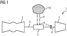
- a single-shaft system 1 has a gas turbine 2, a steam turbine 3 and an electric generator 4.
- the gas turbine 2 and the steam turbine 4 serve to generate rotational energy, wherein the rotational energy is converted in the generator 4 into electrical energy.
- the generator 4 is arranged between the gas turbine 2 and the steam turbine 3.
- the gas turbine 2 has a gas turbine shaft 5 and the steam turbine 3 has a steam turbine shaft 6.
- FIG. 1 It is shown that the generator 4 and the gas turbine 2 are arranged together on the steam turbine shaft 5. However, it is also conceivable that a separate generator shaft is provided for the generator 4, which is coupled by means of a coupling to the gas turbine shaft 5.
- the steam turbine shaft 6 is connected to the gas turbine shaft 5 by means of a clutch 7.
- the clutch 7 is arranged to engage when the steam turbine 3 overhauls the gas turbine 2, which means that the rotational speed of the steam turbine 3 is higher than the rotational speed of the gas turbine 2. Once the clutch 7 is engaged, the gas turbine 2 and the steam turbine 3 rotate at the same speed.
- the clutch 7 is further arranged to disengage when the steam turbine 3 rotates slower than the gas turbine 2.
- the clutch 7 may be, for example, an SSS clutch.
- the gas turbine 2 When starting the one-shaft system 1, the gas turbine 2 is first accelerated, the clutch 7 is disengaged. The waste heat of the gas turbine 2 is used to drive the steam turbine 3. Once the steam turbine 3 is also accelerated, couples the clutch 7 a.
- an electrical load 10 can be connected to an electrical connection 8 of the generator 4.
- the power consumption of the consumer 10 corresponds to an electrical load connected to the generator 4. If now the load connected to the generator 4 drops, without the mass flows of the steam introduced into the steam turbine 3 and / or the fuel introduced into the gas turbine 2 being lowered, this leads to an increase in the rotational speed of the single-shaft system 1
- Switch 9 ensures that when checking the overspeed protection device no electrical load is connected to the generator 4.
- the single-shaft system 1 has an overspeed protection device.
- the overspeed protection device is configured such that a first overspeed protection is triggered when the speed of the steam turbine 3 reaches a steam turbine limit speed 13, and a second overspeed protection is triggered when the speed of the gas turbine 2 reaches a Gasurbinengrenzwertfitiere 14.
- a first overspeed protection is triggered when the speed of the steam turbine 3 reaches a steam turbine limit speed 13
- a second overspeed protection is triggered when the speed of the gas turbine 2 reaches a Gasurbinengrenzwertfitiere 14.
- the first overspeed protection for example, the mass flow of the fuel and / or the mass flow of the steam can be interrupted.
- the mass flow of the fuel can also be interrupted.
- FIG. 2 shows a temporal speed curve of the single-shaft system and FIG. 3 shows the associated temporal performance curves of the gas turbine 2 and the steam turbine 3.
- abscissa 11 is the time in arbitrary Units (wE) and plotted on the ordinate 12, the speed, wherein the speed normalized to the rated speed of the single-shaft system 1 is plotted. Shown are the setpoint speed 15 of the steam turbine 2, the actual speed 16 of the steam turbine 2, the setpoint speed 21 of the gas turbine 3 and the actual speed 22 of the gas turbine 3.
- both the steam turbine limit speed 13 and the gas turbine limit speed 14 are shown, with the gas turbine limit speed 14 being higher than the steam turbine limit speed 13.
- FIG. 3 is the abscissa 17 time in the same arbitrary units as in FIG. 2 and plotted on the ordinate 18 the power.
- the single-shaft system 1 is operated at its rated speed in the time range of 0 to 1 wE.
- both target speeds 15, 21 are continuously raised to a value above the gas turbine limit speed 14, which also increases both actual speeds 16, 22.
- the actual speed 16 of the steam turbine 3 reaches the steam turbine limit speed 13, whereby the first overspeed protection is triggered.
- the mass flow of steam introduced into the steam turbine 3 is interrupted, whereby the clutch 7 disengages.
- the actual speed 22 of the gas turbine 2 reaches the gas turbine limit speed 14, thereby triggering the second overspeed protection.
- the mass flow of the introduced into the gas turbine 2 fuel is interrupted.
- the time course of the power 19 of the steam turbine 3 is characterized in that the power 19 in the time range of 2 to 7 wE continuously increases, and then abruptly drop to zero by triggering the first overspeed protection.
- the associated time course of the performance of the gas turbine 2 is characterized by a continuous drop to the time of 7 wE, then continuously up to the time 11 wE, when the actual speed 16 reaches the gas turbine limit speed 14, to increase continuously.
- the exemplary method for testing an overspeed protection device of a gas turbine 2, a generator 4 and a steam turbine 5 having single-shaft system, wherein the steam turbine 3 is coupled by means of a clutch 7 to the single-shaft system 1, the clutch 7 engages as soon as the steam turbine 3, the gas turbine overhauled, and disengages when the speed of the steam turbine 3 is smaller than that of the gas turbine 2, is carried out with the steps of: a) operating the single-shaft system 1 at its rated speed and wherein no electric load is connected to the generator 4; b) increasing the mass flow of the steam introduced into the steam turbine 3 and / or the fuel introduced into the gas turbine 2 such that the speed of the steam turbine 3 reaches a steam turbine limit speed, wherein the increasing is performed such that the steam turbine 3 accelerates faster than the gas turbine 2 is maintained, whereby the clutch 7 remains engaged, wherein the overspeed protection device is arranged such that a first overspeed protection is triggered when the speed of the steam turbine 3 reaches the steam turbine limit speed; c) Check if
- the steam turbine limit speed may be 106% to 108% of the rated speed and the gas turbine limit speed may be 0.1% to 0.5% greater than the steam turbine limit speed.
Landscapes
- Engineering & Computer Science (AREA)
- Mechanical Engineering (AREA)
- General Engineering & Computer Science (AREA)
- Control Of Turbines (AREA)
- Chemical & Material Sciences (AREA)
- Combustion & Propulsion (AREA)
- Physics & Mathematics (AREA)
- Fluid Mechanics (AREA)
Description
- Die Erfindung betrifft ein Verfahren zum Prüfen einer Überdrehzahlschutzeinrichtung einer Einwellenanlage.
- Bei einer Einwellenanlage zur Erzeugung von elektrischer Energie sind eine Gasturbine, eine Dampfturbine und ein Generator auf einem gemeinsamen Strang angeordnet. Im Normalbetrieb der Einwellenanlage wird die elektrische Energie in ein elektrisches Netz eingespeist und der Strang rotiert mit einer Drehzahl, die der Nenndrehzahl der Einwellenanlage entspricht, wie beispielsweise 50 Hz oder 60 Hz. Bei einem Störfall, insbesondere bei einem Abfall der an dem Generator angeschlossenen elektrischen Last, kann die Drehzahl auf Werte oberhalb der Nenndrehzahl ansteigen. Wenn die Drehzahl eine kritische Drehzahl erreicht, ist eine Synchronität des von dem Generator erzeugten Stroms mit dem Netz nicht mehr gegeben und/oder die Einwellenanlage wird mechanisch und thermisch übermäßig belastet, was in einer Verkürzung der Lebensdauer der Einwellenanlage resultiert.
- Bei Erreichen einer Grenzwertdrehzahl greift eine Überdrehzahlschutzeinrichtung, die ein weiteres Ansteigen der Drehzahl des Strangs unterbindet, wobei die Grenzwertdrehzahl herkömmlich derart gewählt wird, dass sie zwischen der Nenndrehzahl und der kritischen Drehzahl liegt. Herkömmlich wird die Überdrehzahlschutzeinrichtung überprüft, indem die Einwellenanlage in einem Testbetrieb betrieben wird, bei dem die Grenzwertdrehzahl gegenüber der Grenzwertdrehzahl im Normalbetrieb abgesenkt wird, um dadurch während des Testbetriebs eine übermäßige Belastung der Einwellenanlage zu vermeiden.
- Wünschenswert wäre es jedoch im Testbetrieb die gleiche Grenzwertdrehzahl wie im Normalbetrieb zu verwenden. Ein soleher Test ist zudem in einigen Ländern, wie beispielsweise in Südkorea, zwingend vorgeschrieben.
- Aufgabe der Erfindung ist es, ein Verfahren zum Prüfen einer Überdrehzahlschutzeinrichtung einer Einwellenanlage zu schaffen, wobei das Verfahren nicht zu einer übermäßigen Belastung der Einwellenanlage führt.
- Das erfindungsgemäße Verfahren zum Prüfen einer Überdrehzahlschutzeinrichtung einer eine Gasturbine, einen Generator und eine Dampfturbine aufweisenden Einwellenanlage weist die Schritte auf, wie sie in Anspruch 1 definiert sind.
- Indem die Dampfturbinengrenzwertdrehzahl durch Erhöhen des Massenstroms des Brennstoffs und/oder des Dampfs erreicht wird und nicht etwa durch ein Abwerfen einer an den Generator angeschlossenen elektrischen Last, kann die Dampfturbinengrenzwertdrehzahl vorteilhaft langsam angefahren werden und eine kritische Drehzahl der Einwellenanlage vorteilhaft vermieden werden. Dadurch kann eine übermäßige mechanische und thermische Belastung der Einwellenanlage während des Prüfens der Überdrehzahlschutzeinrichtung vermieden werden, wodurch die Lebensdauer der Einwellenanlage lang ist. Die übermäßige Belastung kann mit dem erfindungsgemäßen Verfahren selbst dann vermieden werden, wenn für die Gasturbinengrenzwertdrehzahl und die Dampfturbinengrenzwertdrehzahl die gleichen Grenzwertdrehzahlen wie im Normalbetrieb der Einwellenanlage eingesetzt werden.
- Die Dampfturbine ist mittels einer Kupplung an die Einwellenanlage gekuppelt, wobei die Kupplung einkuppelt, sobald die Dampfturbine die Gasturbine überholt, und auskuppelt, wenn die Drehzahl der Dampfturbine niedriger als die der Gasturbine ist, wobei Schritt b) derart durchgeführt wird, dass die Dampfturbine schneller als die Gasturbine beschleunigt wird, wodurch die Kupplung eingekuppelt bleibt. Dadurch, dass die Kupplung eingekuppelt bleibt rotieren die Gasturbine und die Dampfturbine mit der gleichen Drehzahl, während die Dampfturbine auf ihren Dampfturbinengrenzwert beschleunigt, wodurch es somit vorteilhaft sichergestellt ist, dass dabei die Drehzahl der Gasturbine eine kritische Drehzahl nicht erreicht.
- Das Verfahren wird bevorzugt mit dem Schritt durchgeführt: d) Unterbrechen des Massenstroms des in die Dampfturbine eingeleiteten Dampfs für den Fall, dass der erste Überdrehzahlschutz ausgelöst wird. Das Unterbrechen des Massenstroms des Dampfs wird dazu führen, dass die Kupplung auskuppelt und die Dampfturbine somit unabhängig von der Gasturbine und dem Generator rotiert.
- Es ist bevorzugt, das Verfahren mit den Schritten durchzuführen: e) Erhöhen des Massenstroms des Brennstoffs derart, dass eine Gasturbinengrenzwertdrehzahl erreicht wird, die höher als der Dampfturbinengrenzwertdrehzahl ist, wobei die Überdrehzahlschutzeinrichtung derart eingerichtet ist, dass ein zweiter Überdrehzahlschutz ausgelöst wird, sobald die Drehzahl der Gasturbine die Gasturbinengrenzwertdrehzahl erreicht; f) Prüfen, ob der zweite Überdrehzahlschutz ausgelöst wird. Indem die Gasturbinengrenzwertdrehzahl höher als die Dampfturbinengrenzwertdrehzahl ist, kann somit das Prüfen des zweiten Überdrehzahlschutzes nach erfolgter Prüfung des ersten Überdrehzahlschutzes und unabhängig von dieser Prüfung durchgeführt werden.
- Im Folgenden wird anhand der beigefügten schematischen Zeichnungen das erfindungsgemäße Verfahren näher erläutert. Es zeigen:
- Figur 1
- eine schematische Ansicht einer Einwellenanlage,
- Figur 2
- einen zeitlichen Drehzahlverlauf der Einwellenanlage und
- Figur 3
- einen zeitlichen Leistungsverlauf der Einwellenanlage.
- Wie es aus
Figur 1 ersichtlich ist, weist eine Einwellenanlage 1 eine Gasturbine 2, eine Dampfturbine 3 und einen elektrischen Generator 4 auf. Die Gasturbine 2 und die Dampfturbine 4 dienen zur Erzeugung von Rotationsenergie, wobei die Rotationsenergie in dem Generator 4 in elektrische Energie umgewandelt wird. Der Generator 4 ist zwischen der Gasturbine 2 und der Dampfturbine 3 angeordnet. Die Gasturbine 2 weist eine Gasturbinenwelle 5 und die Dampfturbine 3 weist eine Dampfturbinenwelle 6 auf. InFigur 1 ist dargestellt, dass der Generator 4 und die Gasturbine 2 zusammen auf der Dampfturbinenwelle 5 angeordnet sind. Es ist jedoch ebenfalls denkbar, dass für den Generator 4 eine separate Generatorwelle vorgesehen wird, die mittels einer Kupplung an die Gasturbinenwelle 5 gekuppelt ist. - Die Dampfturbinenwelle 6 ist mittels einer Kupplung 7 mit der Gasturbinenwelle 5 verbunden. Die Kupplung 7 ist derart eingerichtet, dass sie einkuppelt, wenn die Dampfturbine 3 die Gasturbine 2 überholt, was bedeutet, dass die Drehzahl der Dampfturbine 3 höher als die Drehzahl der Gasturbine 2 ist. Sobald die Kupplung 7 eingekuppelt ist, rotieren die Gasturbine 2 und die Dampfturbine 3 mit der gleichen Drehzahl. Die Kupplung 7 ist weiterhin eingerichtet, dass sie auskuppelt, wenn die Dampfturbine 3 langsamer als die Gasturbine 2 dreht. Die Kupplung 7 kann beispielsweise eine SSS-Kupplung sein.
- Beim Anfahren der einen Einwellenanlage 1 wird zunächst die Gasturbine 2 beschleunigt, wobei die Kupplung 7 ausgekuppelt ist. Die Abwärme der Gasturbine 2 wird benutzt, um die Dampfturbine 3 anzutreiben. Sobald die Dampfturbine 3 ebenfalls beschleunigt ist, kuppelt die Kupplung 7 ein.
- Durch Schließen eines Schalters 9 ist ein elektrischer Verbraucher 10 an einen elektrischen Anschluss 8 des Generators 4 anschließbar. Der Stromverbrauch des Verbrauchers 10 entspricht einer an den Generator 4 angeschlossenen elektrischen Last. Fällt nun die an dem Generator 4 angeschlossene Last ab, ohne dass die Massenströme des in die Dampfturbine 3 eingeleiteten Dampfs und/oder des in die Gasturbine 2 eingeleiteten Brennstoffs abgesenkt werden, so führt dies zu einem Ansteigen der Drehzahl der Einwellenanlage 1. Durch Öffnen des Schalters 9 wird sichergestellt, dass beim Prüfen der Überdrehzahlschutzeinrichtung keine elektrische Last an den Generator 4 angeschlossen ist.
- Um ein Ansteigen der Drehzahl der Einwellenanlage 1 auf einen kritischen Wert zu vermeiden, weist die Einwellenanlage 1 eine Überdrehzahlschutzeinrichtung auf. Die Überdrehzahlschutzeinrichtung ist dabei derart eingerichtet, dass ein erster Überdrehzahlschutz ausgelöst wird, sobald die Drehzahl der Dampfturbine 3 eine Dampfturbinengrenzwertdrehzahl 13 erreicht, und ein zweiter Überdrehzahlschutz ausgelöst wird, sobald die Drehzahl der Gasturbine 2 eine Gasturbinengrenzwertdrehzahl 14 erreicht. Bei einem Auslösen des ersten Überdrehzahlschutzes kann beispielsweise der Massenstrom des Brennstoffs und/oder der Massenstrom des Dampfs unterbrochen werden. Bei einem Auslösen des zweiten Überdrehzahlschutzes kann ebenfalls der Massenstrom des Brennstoffs unterbrochen werden.
-
Figur 2 zeigt einen zeitlichen Drehzahlverlauf der Einwellenanlage undFigur 3 zeigt die dazugehörigen zeitlichen Leistungsverläufe der Gasturbine 2 und der Dampfturbine 3. InFigur 2 ist über der Abszisse 11 die Zeit in willkürlichen Einheiten (w.E.) und über der Ordinate 12 die Drehzahl aufgetragen, wobei die Drehzahl normiert auf die Nenndrehzahl der Einwellenanlage 1 aufgetragen ist. Dargestellt sind die Solldrehzahl 15 der Dampfturbine 2, die Istdrehzahl 16 der Dampfturbine 2, die Solldrehzahl 21 der Gasturbine 3 und die Istdrehzahl 22 der Gasturbine 3. Ebenfalls inFigur 2 dargestellt sind sowohl die Dampfturbinengrenzwertdrehzahl 13 als auch die Gasturbinengrenzwertdrehzahl 14, wobei die Gasturbinengrenzwertdrehzahl 14 höher als die Dampfturbinengrenzwertdrehzahl 13 ist. InFigur 3 ist über der Abszisse 17 die Zeit in den gleichen willkürlichen Einheiten wie inFigur 2 und über die Ordinate 18 die Leistung aufgetragen. - Wie es aus
Figuren 2 und 3 ersichtlich ist, wird im Zeitbereich von 0 bis 1 w.E. die Einwellenanlage 1 bei deren Nenndrehzahl betrieben. Im Zeitbereich von 2 bis 6 w.E. werden beide Solldrehzahlen 15, 21 kontinuierlich auf einen Wert oberhalb der Gasturbinengrenzwertdrehzahl 14 angehoben, wodurch sich auch beide Istdrehzahlen 16, 22 erhöht. Bei dem Zeitpunkt von 6 w.E. erreicht die Istdrehzahl 16 der Dampfturbine 3 die Dampfturbinengrenzwertdrehzahl 13, wodurch der erste Überdrehzahlschutz ausgelöst wird. Dadurch wird der Massenstrom des in die Dampfturbine 3 eingeleiteten Dampfs unterbrochen, wodurch die Kupplung 7 auskuppelt. Beim Zeitpunkt von 9 w.E. erreicht die Istdrehzahl 22 der Gasturbine 2 die Gasturbinengrenzwertdrehzahl 14, wodurch der zweite Überdrehzahlschutz ausgelöst wird. Dadurch wird der Massenstrom des in die Gasturbine 2 eingeleiteten Brennstoffs unterbrochen. - Wie es aus
Figur 3 ersichtlich ist, zeichnet sich der zeitliche Verlauf der Leistung 19 der Dampfturbine 3 dadurch aus, dass die Leistung 19 im Zeitbereich von 2 bis 7 w.E. kontinuierlich ansteigt, um dann durch das Auslösen des ersten Überdrehzahlschutzes schlagartig auf Null abzufallen. Der zugehörige zeitliche Verlauf der Leistung der Gasturbine 2 zeichnet sich durch einen kontinuierlichen Abfall bis zum Zeitpunkt von 7 w.E. aus, um anschließend kontinuierlich bis zum Zeitpunkt 11 w.E., wenn die Istdrehzahl 16 die Gasturbinengrenzwertdrehzahl 14 erreicht, kontinuierlich anzusteigen. - Anhand eines Beispiels wird im Folgenden das erfindungsgemäße Verfahren näher erläutert.
- Das beispielhafte Verfahren zum Prüfen einer Überdrehzahlschutzeinrichtung einer eine Gasturbine 2, einen Generator 4 und eine Dampfturbine 5 aufweisenden Einwellenanlage, wobei die Dampfturbine 3 mittels einer Kupplung 7 an die Einwellenanlage 1 gekuppelt ist, wobei die Kupplung 7 einkuppelt, sobald die Dampfturbine 3 die Gasturbine 2 überholt, und auskuppelt, wenn die Drehzahl der Dampfturbine 3 kleiner als die der Gasturbine 2 ist, ist mit den Schritten durchzuführen: a) Betreiben der Einwellenanlage 1 bei deren Nenndrehzahl und wobei an dem Generator 4 keine elektrische Last angeschlossen ist; b) Erhöhen des Massenstroms des in die Dampfturbine 3 eingeleiteten Dampfs und/oder des in Gasturbine 2 eingeleiteten Brennstoffs derart, dass die Drehzahl der Dampfturbine 3 eine Dampfturbinengrenzwertdrehzahl erreicht, wobei das Erhöhen derart durchgeführt wird, dass die Dampfturbine 3 schneller als die Gasturbine 2 beschleunigt wird, wodurch die Kupplung 7 eingekuppelt bleibt, wobei die Überdrehzahlschutzeinrichtung derart eingerichtet ist, dass ein erster Überdrehzahlschutz ausgelöst wird, sobald die Drehzahl der Dampfturbine 3 die Dampfturbinengrenzwertdrehzahl erreicht; c) Prüfen, ob der erste Überdrehzahlschutz ausgelöst wird; d) Unterbrechen des Massenstroms des in die Dampfturbine 3 eingeleiteten Dampfs für den Fall, dass der erste Überdrehzahlschutz ausgelöst wird; e) Erhöhen des Massenstroms des Brennstoffs derart, dass eine Gasturbinengrenzwertdrehzahl erreicht wird, die höher als der Dampfturbinengrenzwertdrehzahl ist, wobei die Überdrehzahlschutzeinrichtung derart eingerichtet ist, dass ein zweiter Überdrehzahlschutz ausgelöst wird, sobald die Drehzahl der Gasturbine 2 die Gasturbinengrenzwertdrehzahl erreicht; f) Prüfen, ob der zweite Überdrehzahlschutz ausgelöst wird.
- Dabei kann die Dampfturbinengrenzwertdrehzahl 106% bis 108% der Nenndrehzahl betragen und die Gasturbinengrenzwertdrehzahl 0,1% bis 0,5% größer als die Dampfturbinengrenzwertdrehzahl sein.
- Obwohl die Erfindung im Detail durch das bevorzugte Ausführungsbeispiel näher illustriert und beschrieben wurde, so ist die Erfindung nicht durch die offenbarten Beispiele eingeschränkt und andere Variationen können vom Fachmann hieraus abgeleitet werden, ohne den Schutzumfang der Erfindung zu verlassen, wie er durch die angehängten Ansprüche definiert ist.
Claims (3)
- Verfahren zum Prüfen einer Überdrehzahlschutzeinrichtung einer eine Gasturbine (2), einen Generator (4) und eine Dampfturbine (5) aufweisenden Einwellenanlage mit den Schritten:a) Betreiben der Einwellenanlage (1) bei deren Nenndrehzahl und wobei an dem Generator (4) keine elektrische Last angeschlossen ist;b) Erhöhen des Massenstroms des in die Dampfturbine (3) eingeleiteten Dampfs und/oder des in Gasturbine (2) eingeleiteten Brennstoffs derart, dass die Drehzahl der Dampfturbine (3) eine Dampfturbinengrenzwertdrehzahl erreicht, wobei die Überdrehzahlschutzeinrichtung derart eingerichtet ist, dass ein erster Überdrehzahlschutz ausgelöst wird, sobald die Drehzahl der Dampfturbine (3) die Dampfturbinengrenzwertdrehzahl erreicht;c) Prüfen, ob der erste Überdrehzahlschutz ausgelöst wird, wobei die Dampfturbine (3) mittels einer Kupplung (7) an die Einwellenanlage (1) gekuppelt ist,wobei die Kupplung (7) einkuppelt, sobald die Dampfturbine (3) die Gasturbine (2) überholt, und auskuppelt, wenn die Drehzahl der Dampfturbine (3) niedriger als die der Gasturbine (2) ist, wobei Schritt b) derart durchgeführt wird, dass die Dampfturbine (3) schneller als die Gasturbine (2) beschleunigt wird, wodurch die Kupplung (7) eingekuppelt bleibt.
- Verfahren gemäß Anspruch 1,
mit dem Schritt:
d) Unterbrechen des Massenstroms des in die Dampfturbine (3) eingeleiteten Dampfs für den Fall, dass der erste Überdrehzahlschutz ausgelöst wird. - Verfahren gemäß einem der Ansprüche 1 oder 2,
mit den Schritten:e) Erhöhen des Massenstroms des Brennstoffs derart, dass eine Gasturbinengrenzwertdrehzahl erreicht wird, die höher als der Dampfturbinengrenzwertdrehzahl ist, wobei die Überdrehzahlschutzeinrichtung derart eingerichtet ist, dass ein zweiter Überdrehzahlschutz ausgelöst wird, sobald die Drehzahl der Gasturbine (2) die Gasturbinengrenzwertdrehzahl erreicht;f) Prüfen, ob der zweite Überdrehzahlschutz ausgelöst wird.
Priority Applications (1)
| Application Number | Priority Date | Filing Date | Title |
|---|---|---|---|
| EP14771218.6A EP3044428B1 (de) | 2013-09-17 | 2014-09-08 | Verfahren zum testen einer überdrehzahlschutzeinrichtung einer einwellenanlage |
Applications Claiming Priority (3)
| Application Number | Priority Date | Filing Date | Title |
|---|---|---|---|
| EP13184817.8A EP2848772A1 (de) | 2013-09-17 | 2013-09-17 | Verfahren zum Testen einer Überdrehzahlschutzeinrichtung einer Einwellenanlage |
| EP14771218.6A EP3044428B1 (de) | 2013-09-17 | 2014-09-08 | Verfahren zum testen einer überdrehzahlschutzeinrichtung einer einwellenanlage |
| PCT/EP2014/069071 WO2015039910A1 (de) | 2013-09-17 | 2014-09-08 | Verfahren zum testen einer überdrehzahlschutzeinrichtung einer einwellenanlage |
Publications (2)
| Publication Number | Publication Date |
|---|---|
| EP3044428A1 EP3044428A1 (de) | 2016-07-20 |
| EP3044428B1 true EP3044428B1 (de) | 2019-05-15 |
Family
ID=49182153
Family Applications (2)
| Application Number | Title | Priority Date | Filing Date |
|---|---|---|---|
| EP13184817.8A Withdrawn EP2848772A1 (de) | 2013-09-17 | 2013-09-17 | Verfahren zum Testen einer Überdrehzahlschutzeinrichtung einer Einwellenanlage |
| EP14771218.6A Not-in-force EP3044428B1 (de) | 2013-09-17 | 2014-09-08 | Verfahren zum testen einer überdrehzahlschutzeinrichtung einer einwellenanlage |
Family Applications Before (1)
| Application Number | Title | Priority Date | Filing Date |
|---|---|---|---|
| EP13184817.8A Withdrawn EP2848772A1 (de) | 2013-09-17 | 2013-09-17 | Verfahren zum Testen einer Überdrehzahlschutzeinrichtung einer Einwellenanlage |
Country Status (3)
| Country | Link |
|---|---|
| EP (2) | EP2848772A1 (de) |
| KR (1) | KR101834099B1 (de) |
| WO (1) | WO2015039910A1 (de) |
Families Citing this family (2)
| Publication number | Priority date | Publication date | Assignee | Title |
|---|---|---|---|---|
| US12241378B2 (en) | 2021-01-26 | 2025-03-04 | Yantai Jereh Petroleum Equipment & Technologies Co., Ltd. | Gas turbine overspeed protection method and apparatus, electronic device and storage medium |
| CN114382597B (zh) * | 2021-11-10 | 2023-10-27 | 烟台杰瑞石油装备技术有限公司 | 燃气轮机超速保护方法、装置、电子设备及可读存储介质 |
Family Cites Families (6)
| Publication number | Priority date | Publication date | Assignee | Title |
|---|---|---|---|---|
| US5199256A (en) * | 1989-01-26 | 1993-04-06 | General Electric Company | Overspeed protection for a gas turbine/steam turbine combined cycle |
| US5301499A (en) * | 1990-06-28 | 1994-04-12 | General Electric Company | Overspeed anticipation and control system for single shaft combined cycle gas and steam turbine unit |
| JP3930462B2 (ja) * | 2003-08-01 | 2007-06-13 | 株式会社日立製作所 | 一軸コンバインドサイクル発電設備及びその運転方法 |
| US8756939B2 (en) * | 2010-03-23 | 2014-06-24 | General Electric Company | Method and system for testing an overspeed protection system of a powerplant machine |
| US8365583B2 (en) * | 2010-03-23 | 2013-02-05 | General Electric Company | Method and system for testing an overspeed protection system of a powerplant machine |
| FR2962165B1 (fr) * | 2010-07-02 | 2014-05-02 | Turbomeca | Detection de survitesse d'une turbine libre par mesure sur couplemetre |
-
2013
- 2013-09-17 EP EP13184817.8A patent/EP2848772A1/de not_active Withdrawn
-
2014
- 2014-09-08 WO PCT/EP2014/069071 patent/WO2015039910A1/de not_active Ceased
- 2014-09-08 EP EP14771218.6A patent/EP3044428B1/de not_active Not-in-force
- 2014-09-08 KR KR1020167006647A patent/KR101834099B1/ko active Active
Non-Patent Citations (1)
| Title |
|---|
| None * |
Also Published As
| Publication number | Publication date |
|---|---|
| EP2848772A1 (de) | 2015-03-18 |
| EP3044428A1 (de) | 2016-07-20 |
| WO2015039910A1 (de) | 2015-03-26 |
| KR101834099B1 (ko) | 2018-03-02 |
| KR20160042449A (ko) | 2016-04-19 |
Similar Documents
| Publication | Publication Date | Title |
|---|---|---|
| EP3017150B1 (de) | Verfahren zum prüfen einer überdrehzahlschutzeinrichtung einer einwellenanlage | |
| DE102009057062A1 (de) | Verfahren zum Betrieb einer drehzahlgeregelten Windenergieanlage sowie eine solche Windenergieanlage | |
| EP3055515B1 (de) | Verfahren zum prüfen einer überdrehzahlschutzeinrichtung einer einwellenanlage | |
| EP2848772A1 (de) | Verfahren zum Testen einer Überdrehzahlschutzeinrichtung einer Einwellenanlage | |
| EP2265816B1 (de) | Doppelt gespeister asynchrongenerator und verfahren zu dessen betrieb | |
| CH715032A2 (de) | Vorrichtung zur Luftversorgung einer Brennstoffzelle. | |
| EP2640970B1 (de) | Windenergieanlage und verfahren zum betreiben einer windenergieanlage mit temperaturüberwachung des transformators | |
| EP3022402B1 (de) | Verfahren zum prüfen einer überdrehzahlschutzeinrichtung einer einwellenanlage | |
| EP3022401B1 (de) | Verfahren zum testen einer überdrehzahlschutzeinrichtung einer einwellenanlage | |
| DE2159696A1 (de) | Verfahren zur Verbesserung der Nachwärmeabfuhr bei einer Notabschaltung eines gasgekühlten Kernreaktors sowie Vorrichtung zur Durchführung des Verfahrens | |
| EP2984301B1 (de) | Verfahren zum testen eines überdrehzahlschutzes einer gud-einwellenanlage | |
| EP3238338B1 (de) | Verfahren sowie vorrichtung zum überwachen des betriebes einer stromerzeugungsanlage | |
| DE102018215222A1 (de) | Verfahren zum Abbau einer Restenergie einer elektrischen Maschine eines Kraftwerks im Falle eines plötzlichen Lastabfalls | |
| DE102012006141B4 (de) | Abgaswärmenutzsystem | |
| EP3246538A1 (de) | Verfahren zum kuppeln einer dampfturbine und einer gasturbine mit einem gewünschten differenzwinkel unter nutzung einer sollbeschleunigung | |
| EP1870565A1 (de) | Vermeidung unzulässig hoher Drehzahlen an Turbosätzen | |
| EP2930320A1 (de) | Verfahren zum Betreiben einer Dampfturbine | |
| EP3285079B1 (de) | Schutzverfahren zum schützen eines generators oder kraftwerksblocks sowie schutzeinrichtung zur durchführung eines solchen verfahrens | |
| EP2899373A1 (de) | Betriebsverfahren einer stationären Gasturbine bei Lastabwurf | |
| EP3511535A1 (de) | Anlage und verfahren zum betreiben einer anlage | |
| DE102024208869A1 (de) | Expansionskraftwerk und Verfahren zum Betreiben eines solchen Kraftwerks | |
| DE102016217216A1 (de) | Turbinensystem sowie Verfahren zum Betreiben eines Turbinensystems | |
| DE1476722A1 (de) | Offene Gasturbinenanlage | |
| DE102017115983A1 (de) | Hybridmodul-Schutzsystem, Verfahren zur zumindest anteiligen Entfernung von Wasser aus einem Hybridmodul, einen Antriebsstrang und ein Kraftfahrzeug |
Legal Events
| Date | Code | Title | Description |
|---|---|---|---|
| PUAI | Public reference made under article 153(3) epc to a published international application that has entered the european phase |
Free format text: ORIGINAL CODE: 0009012 |
|
| 17P | Request for examination filed |
Effective date: 20160218 |
|
| AK | Designated contracting states |
Kind code of ref document: A1 Designated state(s): AL AT BE BG CH CY CZ DE DK EE ES FI FR GB GR HR HU IE IS IT LI LT LU LV MC MK MT NL NO PL PT RO RS SE SI SK SM TR |
|
| AX | Request for extension of the european patent |
Extension state: BA ME |
|
| DAX | Request for extension of the european patent (deleted) | ||
| RAP1 | Party data changed (applicant data changed or rights of an application transferred) |
Owner name: SIEMENS AKTIENGESELLSCHAFT |
|
| GRAP | Despatch of communication of intention to grant a patent |
Free format text: ORIGINAL CODE: EPIDOSNIGR1 |
|
| STAA | Information on the status of an ep patent application or granted ep patent |
Free format text: STATUS: GRANT OF PATENT IS INTENDED |
|
| INTG | Intention to grant announced |
Effective date: 20181219 |
|
| GRAS | Grant fee paid |
Free format text: ORIGINAL CODE: EPIDOSNIGR3 |
|
| GRAA | (expected) grant |
Free format text: ORIGINAL CODE: 0009210 |
|
| STAA | Information on the status of an ep patent application or granted ep patent |
Free format text: STATUS: THE PATENT HAS BEEN GRANTED |
|
| AK | Designated contracting states |
Kind code of ref document: B1 Designated state(s): AL AT BE BG CH CY CZ DE DK EE ES FI FR GB GR HR HU IE IS IT LI LT LU LV MC MK MT NL NO PL PT RO RS SE SI SK SM TR |
|
| REG | Reference to a national code |
Ref country code: CH Ref legal event code: EP |
|
| REG | Reference to a national code |
Ref country code: DE Ref legal event code: R096 Ref document number: 502014011730 Country of ref document: DE |
|
| REG | Reference to a national code |
Ref country code: IE Ref legal event code: FG4D Free format text: LANGUAGE OF EP DOCUMENT: GERMAN |
|
| REG | Reference to a national code |
Ref country code: NL Ref legal event code: MP Effective date: 20190515 |
|
| REG | Reference to a national code |
Ref country code: LT Ref legal event code: MG4D |
|
| PG25 | Lapsed in a contracting state [announced via postgrant information from national office to epo] |
Ref country code: FI Free format text: LAPSE BECAUSE OF FAILURE TO SUBMIT A TRANSLATION OF THE DESCRIPTION OR TO PAY THE FEE WITHIN THE PRESCRIBED TIME-LIMIT Effective date: 20190515 Ref country code: LT Free format text: LAPSE BECAUSE OF FAILURE TO SUBMIT A TRANSLATION OF THE DESCRIPTION OR TO PAY THE FEE WITHIN THE PRESCRIBED TIME-LIMIT Effective date: 20190515 Ref country code: NL Free format text: LAPSE BECAUSE OF FAILURE TO SUBMIT A TRANSLATION OF THE DESCRIPTION OR TO PAY THE FEE WITHIN THE PRESCRIBED TIME-LIMIT Effective date: 20190515 Ref country code: AL Free format text: LAPSE BECAUSE OF FAILURE TO SUBMIT A TRANSLATION OF THE DESCRIPTION OR TO PAY THE FEE WITHIN THE PRESCRIBED TIME-LIMIT Effective date: 20190515 Ref country code: ES Free format text: LAPSE BECAUSE OF FAILURE TO SUBMIT A TRANSLATION OF THE DESCRIPTION OR TO PAY THE FEE WITHIN THE PRESCRIBED TIME-LIMIT Effective date: 20190515 Ref country code: SE Free format text: LAPSE BECAUSE OF FAILURE TO SUBMIT A TRANSLATION OF THE DESCRIPTION OR TO PAY THE FEE WITHIN THE PRESCRIBED TIME-LIMIT Effective date: 20190515 Ref country code: HR Free format text: LAPSE BECAUSE OF FAILURE TO SUBMIT A TRANSLATION OF THE DESCRIPTION OR TO PAY THE FEE WITHIN THE PRESCRIBED TIME-LIMIT Effective date: 20190515 Ref country code: PT Free format text: LAPSE BECAUSE OF FAILURE TO SUBMIT A TRANSLATION OF THE DESCRIPTION OR TO PAY THE FEE WITHIN THE PRESCRIBED TIME-LIMIT Effective date: 20190915 Ref country code: NO Free format text: LAPSE BECAUSE OF FAILURE TO SUBMIT A TRANSLATION OF THE DESCRIPTION OR TO PAY THE FEE WITHIN THE PRESCRIBED TIME-LIMIT Effective date: 20190815 |
|
| PG25 | Lapsed in a contracting state [announced via postgrant information from national office to epo] |
Ref country code: GR Free format text: LAPSE BECAUSE OF FAILURE TO SUBMIT A TRANSLATION OF THE DESCRIPTION OR TO PAY THE FEE WITHIN THE PRESCRIBED TIME-LIMIT Effective date: 20190816 Ref country code: RS Free format text: LAPSE BECAUSE OF FAILURE TO SUBMIT A TRANSLATION OF THE DESCRIPTION OR TO PAY THE FEE WITHIN THE PRESCRIBED TIME-LIMIT Effective date: 20190515 Ref country code: LV Free format text: LAPSE BECAUSE OF FAILURE TO SUBMIT A TRANSLATION OF THE DESCRIPTION OR TO PAY THE FEE WITHIN THE PRESCRIBED TIME-LIMIT Effective date: 20190515 Ref country code: BG Free format text: LAPSE BECAUSE OF FAILURE TO SUBMIT A TRANSLATION OF THE DESCRIPTION OR TO PAY THE FEE WITHIN THE PRESCRIBED TIME-LIMIT Effective date: 20190815 |
|
| PG25 | Lapsed in a contracting state [announced via postgrant information from national office to epo] |
Ref country code: SK Free format text: LAPSE BECAUSE OF FAILURE TO SUBMIT A TRANSLATION OF THE DESCRIPTION OR TO PAY THE FEE WITHIN THE PRESCRIBED TIME-LIMIT Effective date: 20190515 Ref country code: EE Free format text: LAPSE BECAUSE OF FAILURE TO SUBMIT A TRANSLATION OF THE DESCRIPTION OR TO PAY THE FEE WITHIN THE PRESCRIBED TIME-LIMIT Effective date: 20190515 Ref country code: RO Free format text: LAPSE BECAUSE OF FAILURE TO SUBMIT A TRANSLATION OF THE DESCRIPTION OR TO PAY THE FEE WITHIN THE PRESCRIBED TIME-LIMIT Effective date: 20190515 Ref country code: DK Free format text: LAPSE BECAUSE OF FAILURE TO SUBMIT A TRANSLATION OF THE DESCRIPTION OR TO PAY THE FEE WITHIN THE PRESCRIBED TIME-LIMIT Effective date: 20190515 |
|
| REG | Reference to a national code |
Ref country code: DE Ref legal event code: R097 Ref document number: 502014011730 Country of ref document: DE |
|
| PG25 | Lapsed in a contracting state [announced via postgrant information from national office to epo] |
Ref country code: SM Free format text: LAPSE BECAUSE OF FAILURE TO SUBMIT A TRANSLATION OF THE DESCRIPTION OR TO PAY THE FEE WITHIN THE PRESCRIBED TIME-LIMIT Effective date: 20190515 Ref country code: IT Free format text: LAPSE BECAUSE OF FAILURE TO SUBMIT A TRANSLATION OF THE DESCRIPTION OR TO PAY THE FEE WITHIN THE PRESCRIBED TIME-LIMIT Effective date: 20190515 |
|
| PLBE | No opposition filed within time limit |
Free format text: ORIGINAL CODE: 0009261 |
|
| STAA | Information on the status of an ep patent application or granted ep patent |
Free format text: STATUS: NO OPPOSITION FILED WITHIN TIME LIMIT |
|
| PG25 | Lapsed in a contracting state [announced via postgrant information from national office to epo] |
Ref country code: TR Free format text: LAPSE BECAUSE OF FAILURE TO SUBMIT A TRANSLATION OF THE DESCRIPTION OR TO PAY THE FEE WITHIN THE PRESCRIBED TIME-LIMIT Effective date: 20190515 |
|
| REG | Reference to a national code |
Ref country code: DE Ref legal event code: R119 Ref document number: 502014011730 Country of ref document: DE |
|
| 26N | No opposition filed |
Effective date: 20200218 |
|
| PG25 | Lapsed in a contracting state [announced via postgrant information from national office to epo] |
Ref country code: PL Free format text: LAPSE BECAUSE OF FAILURE TO SUBMIT A TRANSLATION OF THE DESCRIPTION OR TO PAY THE FEE WITHIN THE PRESCRIBED TIME-LIMIT Effective date: 20190515 |
|
| PG25 | Lapsed in a contracting state [announced via postgrant information from national office to epo] |
Ref country code: MC Free format text: LAPSE BECAUSE OF FAILURE TO SUBMIT A TRANSLATION OF THE DESCRIPTION OR TO PAY THE FEE WITHIN THE PRESCRIBED TIME-LIMIT Effective date: 20190515 Ref country code: SI Free format text: LAPSE BECAUSE OF FAILURE TO SUBMIT A TRANSLATION OF THE DESCRIPTION OR TO PAY THE FEE WITHIN THE PRESCRIBED TIME-LIMIT Effective date: 20190515 |
|
| REG | Reference to a national code |
Ref country code: CH Ref legal event code: PL |
|
| PG25 | Lapsed in a contracting state [announced via postgrant information from national office to epo] |
Ref country code: CH Free format text: LAPSE BECAUSE OF NON-PAYMENT OF DUE FEES Effective date: 20190930 Ref country code: DE Free format text: LAPSE BECAUSE OF NON-PAYMENT OF DUE FEES Effective date: 20200401 Ref country code: LU Free format text: LAPSE BECAUSE OF NON-PAYMENT OF DUE FEES Effective date: 20190908 Ref country code: IE Free format text: LAPSE BECAUSE OF NON-PAYMENT OF DUE FEES Effective date: 20190908 Ref country code: LI Free format text: LAPSE BECAUSE OF NON-PAYMENT OF DUE FEES Effective date: 20190930 |
|
| REG | Reference to a national code |
Ref country code: BE Ref legal event code: MM Effective date: 20190930 |
|
| PG25 | Lapsed in a contracting state [announced via postgrant information from national office to epo] |
Ref country code: BE Free format text: LAPSE BECAUSE OF NON-PAYMENT OF DUE FEES Effective date: 20190930 |
|
| GBPC | Gb: european patent ceased through non-payment of renewal fee |
Effective date: 20190908 |
|
| PG25 | Lapsed in a contracting state [announced via postgrant information from national office to epo] |
Ref country code: GB Free format text: LAPSE BECAUSE OF NON-PAYMENT OF DUE FEES Effective date: 20190908 |
|
| PGFP | Annual fee paid to national office [announced via postgrant information from national office to epo] |
Ref country code: CZ Payment date: 20200908 Year of fee payment: 7 Ref country code: FR Payment date: 20200921 Year of fee payment: 7 |
|
| REG | Reference to a national code |
Ref country code: AT Ref legal event code: MM01 Ref document number: 1133680 Country of ref document: AT Kind code of ref document: T Effective date: 20190908 |
|
| PG25 | Lapsed in a contracting state [announced via postgrant information from national office to epo] |
Ref country code: AT Free format text: LAPSE BECAUSE OF NON-PAYMENT OF DUE FEES Effective date: 20190908 |
|
| PG25 | Lapsed in a contracting state [announced via postgrant information from national office to epo] |
Ref country code: CY Free format text: LAPSE BECAUSE OF FAILURE TO SUBMIT A TRANSLATION OF THE DESCRIPTION OR TO PAY THE FEE WITHIN THE PRESCRIBED TIME-LIMIT Effective date: 20190515 |
|
| PG25 | Lapsed in a contracting state [announced via postgrant information from national office to epo] |
Ref country code: IS Free format text: LAPSE BECAUSE OF FAILURE TO SUBMIT A TRANSLATION OF THE DESCRIPTION OR TO PAY THE FEE WITHIN THE PRESCRIBED TIME-LIMIT Effective date: 20190915 |
|
| PG25 | Lapsed in a contracting state [announced via postgrant information from national office to epo] |
Ref country code: HU Free format text: LAPSE BECAUSE OF FAILURE TO SUBMIT A TRANSLATION OF THE DESCRIPTION OR TO PAY THE FEE WITHIN THE PRESCRIBED TIME-LIMIT; INVALID AB INITIO Effective date: 20140908 Ref country code: MT Free format text: LAPSE BECAUSE OF FAILURE TO SUBMIT A TRANSLATION OF THE DESCRIPTION OR TO PAY THE FEE WITHIN THE PRESCRIBED TIME-LIMIT Effective date: 20190515 |
|
| PG25 | Lapsed in a contracting state [announced via postgrant information from national office to epo] |
Ref country code: CZ Free format text: LAPSE BECAUSE OF NON-PAYMENT OF DUE FEES Effective date: 20210908 |
|
| PG25 | Lapsed in a contracting state [announced via postgrant information from national office to epo] |
Ref country code: MK Free format text: LAPSE BECAUSE OF FAILURE TO SUBMIT A TRANSLATION OF THE DESCRIPTION OR TO PAY THE FEE WITHIN THE PRESCRIBED TIME-LIMIT Effective date: 20190515 |
|
| PG25 | Lapsed in a contracting state [announced via postgrant information from national office to epo] |
Ref country code: FR Free format text: LAPSE BECAUSE OF NON-PAYMENT OF DUE FEES Effective date: 20210930 |