EP3043147B1 - Ratiometrisches nuklearmagnetkernresonanzgyroskop - Google Patents
Ratiometrisches nuklearmagnetkernresonanzgyroskop Download PDFInfo
- Publication number
- EP3043147B1 EP3043147B1 EP16150518.5A EP16150518A EP3043147B1 EP 3043147 B1 EP3043147 B1 EP 3043147B1 EP 16150518 A EP16150518 A EP 16150518A EP 3043147 B1 EP3043147 B1 EP 3043147B1
- Authority
- EP
- European Patent Office
- Prior art keywords
- frequency
- precession
- gyromagnetic
- magnetic field
- sum
- Prior art date
- Legal status (The legal status is an assumption and is not a legal conclusion. Google has not performed a legal analysis and makes no representation as to the accuracy of the status listed.)
- Active
Links
- 238000005481 NMR spectroscopy Methods 0.000 title claims description 94
- 238000001514 detection method Methods 0.000 claims description 75
- 230000003287 optical effect Effects 0.000 claims description 48
- 239000000523 sample Substances 0.000 claims description 33
- 150000001340 alkali metals Chemical class 0.000 claims description 28
- 229910052783 alkali metal Inorganic materials 0.000 claims description 23
- 238000000034 method Methods 0.000 claims description 11
- 238000005070 sampling Methods 0.000 description 3
- 238000010521 absorption reaction Methods 0.000 description 2
- 229910052792 caesium Inorganic materials 0.000 description 2
- TVFDJXOCXUVLDH-UHFFFAOYSA-N caesium atom Chemical compound [Cs] TVFDJXOCXUVLDH-UHFFFAOYSA-N 0.000 description 2
- 230000000694 effects Effects 0.000 description 2
- 229910052701 rubidium Inorganic materials 0.000 description 2
- IGLNJRXAVVLDKE-UHFFFAOYSA-N rubidium atom Chemical compound [Rb] IGLNJRXAVVLDKE-UHFFFAOYSA-N 0.000 description 2
- 230000001360 synchronised effect Effects 0.000 description 2
- 229910052724 xenon Inorganic materials 0.000 description 2
- FHNFHKCVQCLJFQ-UHFFFAOYSA-N xenon atom Chemical compound [Xe] FHNFHKCVQCLJFQ-UHFFFAOYSA-N 0.000 description 2
- 239000013078 crystal Substances 0.000 description 1
- 239000011521 glass Substances 0.000 description 1
- 229910052734 helium Inorganic materials 0.000 description 1
- 239000001307 helium Substances 0.000 description 1
- SWQJXJOGLNCZEY-UHFFFAOYSA-N helium atom Chemical compound [He] SWQJXJOGLNCZEY-UHFFFAOYSA-N 0.000 description 1
- 230000003993 interaction Effects 0.000 description 1
- 229910052743 krypton Inorganic materials 0.000 description 1
- DNNSSWSSYDEUBZ-UHFFFAOYSA-N krypton atom Chemical compound [Kr] DNNSSWSSYDEUBZ-UHFFFAOYSA-N 0.000 description 1
- 238000005259 measurement Methods 0.000 description 1
- 230000000116 mitigating effect Effects 0.000 description 1
- 229910052756 noble gas Inorganic materials 0.000 description 1
- -1 rubidium or cesium Chemical class 0.000 description 1
Images
Classifications
-
- G—PHYSICS
- G01—MEASURING; TESTING
- G01C—MEASURING DISTANCES, LEVELS OR BEARINGS; SURVEYING; NAVIGATION; GYROSCOPIC INSTRUMENTS; PHOTOGRAMMETRY OR VIDEOGRAMMETRY
- G01C19/00—Gyroscopes; Turn-sensitive devices using vibrating masses; Turn-sensitive devices without moving masses; Measuring angular rate using gyroscopic effects
- G01C19/58—Turn-sensitive devices without moving masses
- G01C19/60—Electronic or nuclear magnetic resonance gyrometers
- G01C19/62—Electronic or nuclear magnetic resonance gyrometers with optical pumping
-
- G—PHYSICS
- G01—MEASURING; TESTING
- G01R—MEASURING ELECTRIC VARIABLES; MEASURING MAGNETIC VARIABLES
- G01R33/00—Arrangements or instruments for measuring magnetic variables
- G01R33/20—Arrangements or instruments for measuring magnetic variables involving magnetic resonance
- G01R33/24—Arrangements or instruments for measuring magnetic variables involving magnetic resonance for measuring direction or magnitude of magnetic fields or magnetic flux
- G01R33/26—Arrangements or instruments for measuring magnetic variables involving magnetic resonance for measuring direction or magnitude of magnetic fields or magnetic flux using optical pumping
Definitions
- the present invention relates generally to sensor systems, and specifically to a ratiometric magnetic resonance (NMR) gyroscope system.
- NMR ratiometric magnetic resonance
- a typical nuclear magnetic resonance (NMR) gyroscope operates on the principle of sensing inertial angular rotation rate or orientation angle about a sensitive axis based on a shift in the measured Larmor precession frequency or phase of one or two isotopes that possess nuclear magnetic moments.
- An NMR gyroscope system can include a vapor cell and a rotation sensor that includes, for example, a light source, a photodetector, and signal processing circuitry.
- the vapor cell can contain one or more alkali metals, such as rubidium or cesium, together with one or more gyromagnetic isotopes that are caused to precess in response to a magnetic field.
- the signal processing circuitry can extract the Larmor precession frequency and/or phase information of the one or more gyromagnetic isotopes. As a result, a gyroscope rotation rate or orientation angle about the sensitive axis can be calculated based on the extracted Larmor precession frequencies and phase information.
- US 4 157 495 A discloses a nuclear magnetic resonance gyroscope that operates on the principle of sensing angular rotation rate as a shift in the Larmor frequency of one or more nuclear species that possess nuclear magnetic moments.
- WO 2012/106094 A1 discloses an atom beam gyroscope system.
- the system includes an atom beam system that generates an atom beam comprising alkali metal atoms along a length of a detection region orthogonal to a sensitive axis.
- the system also includes a detection system comprising a detection laser and photodetector.
- the detection laser can generate an optical detection beam that illuminates the detection region to pump the alkali metal atoms.
- the photodetector can measure an optical absorption of the optical detection beam by the alkali metal atoms in the atom beam and to generate an intensity signal associated with the measured optical absorption.
- the system further includes a gyroscope sensor configured to calculate rotation of the atom beam gyroscope system about the sensitive axis based on a magnitude of the intensity signal due to a Doppler-shift in energy of the alkali metal atoms in the atom beam.
- a gyroscope sensor configured to calculate rotation of the atom beam gyroscope system about the sensitive axis based on a magnitude of the intensity signal due to a Doppler-shift in energy of the alkali metal atoms in the atom beam.
- An NMR gyroscope system includes a vapor cell comprising an alkali metal, a first gyromagnetic isotope, and a second gyromagnetic isotope; a pump laser configured to generate an optical pump beam; a magnetic field generator configured to generate a magnetic field that is substantially aligned with a sensitive axis to cause the first and second gyromagnetic isotopes to counter-precess based on the optical pump beam and the alkali metal; a probe laser configured to provide an optical probe beam through the vapor cell that exits the vapor cell as a detection beam; and a detection system configured to monitor the detection beam, to generate a reference frequency based on a predetermined constant ratio of the precession frequencies of the first and second gyromagnetic isotopes and to determine a rotation of the NMR gyroscope system about the sensitive axis, wherein the detection system comprises:
- the present invention relates generally to sensor systems, and specifically to a ratiometric nuclear magnetic resonance (NMR) gyroscope system.
- the NMR gyroscope system can include a vapor cell having alkali metal, a first gyromagnetic isotope and a second gyromagnetic isotope.
- a magnetic field generator can generate a substantially uniform magnetic field that is provided through the vapor cell and which is aligned with a sensitive axis of the NMR gyroscope system.
- a pump laser can generate an optical pump beam that is provided through the vapor cell to spin-polarize the alkali metal, thus facilitating precession of the alkali metal and the gyromagnetic isotopes in response to the magnetic field.
- the pump laser can be configured to generate the optical pump beam as a linearly-polarized beam that is circularly-polarized via a quarter-wave plate before being provided through the vapor cell.
- a probe laser can generate an optical probe beam that can likewise be provided through the vapor cell in a direction that is orthogonal with respect to the optical pump beam, and which exits the vapor cell as a detection beam.
- a detection system can be configured to monitor the detection beam to calculate a rotation of the NMR gyroscope system about the sensitive axis.
- the detection system can be configured to monitor a Faraday rotation of the optical probe beam resulting from a precession of the gyromagnetic isotopes.
- the detection system can be configured to generate a reference frequency that can be based on a predetermined ratio between the precession of the first and second gyromagnetic isotopes and based on a clock signal.
- the clock signal can also be implemented to control a digital reference counter that can correspond to a frequency of the first gyromagnetic isotope precessing in free inertial space based on the magnetic field.
- the detection system can include a phase-locked loop configured to phase-lock a sum of the frequencies of the first and second gyromagnetic isotopes with the reference frequency, such that a difference between the digital reference counter value and the frequency of the first gyromagnetic isotope can correspond to rotation of the NMR gyroscope system about the sensitive axis.
- the value of the digital reference counter can be latched based on the frequency of the first gyromagnetic isotope to provide a difference between the period of the digital reference counter and the frequency of the first gyromagnetic isotope, which thus corresponds to rotation of the NMR gyroscope system about the sensitive axis.
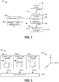
- FIG. 1 illustrates an example of a nuclear magnetic resonance (NMR) gyroscope system 10.
- the NMR gyroscope system 10 can be implemented in any of a variety of applications.
- the NMR gyroscope system 10 can be implemented in navigation systems for aircraft and/or spacecraft.
- the NMR gyroscope system 10 can be a portion of a multi-axis gyroscope system, such as demonstrated in greater detail in the example of FIG. 3 .
- the NMR gyroscope system 10 includes a vapor cell 12 that can be, for example, a glass casing of any of a variety of shapes and sizes.
- the vapor cell 12 includes an alkali metal 14, a first gyromagnetic isotope 16, and a second gyromagnetic isotope 18.
- the alkali metal 14 can be Rubidium (Rb) or Cesium (Cs) vapor.
- the gyromagnetic isotopes 16 and 18 can include any of a variety of noble gas isotopes, such as 3 Helium, 83 Krypton, 129 Xenon, and/or 131 Xenon.
- the NMR gyroscope system 10 also includes a magnetic field generator 20 that is configured to generate a net magnetic field B Z through the vapor cell 12.
- the magnetic field B Z can include an AC modulated DC magnetic field, and thus an AC component and a DC component, that is provided through the vapor cell 12 and which is aligned with a sensitive axis of the NMR gyroscope system 10.
- the magnetic field generator 20 can be configured as a magnetic solenoid that substantially surrounds the vapor cell 12.
- the NMR gyroscope system 10 can include a magnetic shield (not shown) that can substantially surround the vapor cell 12, thus substantially mitigating interference from external magnetic fields, such as from the Earth magnetic field.
- the NMR gyroscope system 10 also includes a pump laser 22 configured to generate an optical pump beam OPT PMP .
- the optical pump beam OPT PMP is provided through the vapor cell 12, such as along the sensitive axis of the NMR gyroscope system 10 about which a rotation of the NMR gyroscope system 10 is determined.
- the optical pump beam OPT PMP can be generated at a wavelength that can be on-resonance with the alkali metal 14, such as corresponding to either a D1 or a D2 emission line associated with an alkali metal 14.
- the optical pump beam OPT PMP can be provided through the vapor cell 12 at a circular-polarization (e.g., via a quarter-wave plate).
- the circular-polarization of the optical pump beam OPT PMP can thus spin-polarize the alkali metal 14 based on an angular momentum of the photons therein to facilitate precession of the alkali metal 14 based on the magnetic field B Z .
- the precession of the alkali metal 14 can thus facilitate precession of the gyromagnetic isotopes 16 and 18 via spin-exchange interaction between the gyromagnetic isotopes 16 and 18 and the alkali metal 14.
- the gyromagnetic isotopes 16 and 18 can be selected to counter-precess in response to the magnetic field B Z , and thus precess in opposite directions, such that a sum of the precession of the gyromagnetic isotopes 16 and 18 is independent of the rotation of the NMR gyroscope system 10 about the sensitive axis, and is thus substantially constant at a substantially constant magnitude of the magnetic field B Z .
- the NMR gyroscope system 10 also includes a probe laser 24 configured to generate an optical probe beam OPT PRB .
- the optical probe beam OPT PRB can be generated at a wavelength that is substantially off-resonance with the alkali metal 14.
- the optical probe beam OPT PRB is provided through the vapor cell 12, such as in a direction that is orthogonal with respect to the optical pump beam OPT PMP , and exits the vapor cell 12 as a detection beam OPT DET .
- the NMR gyroscope system 10 also includes a detection system 26 that is configured to monitor the detection beam OPT DET to determine a rotation of the NMR gyroscope system 10 about the sensitive axis.
- the detection system 26 can be configured to determine the rotation angle of the NMR gyroscope system 10 about the sensitive axis based on the measured precession angle of one or both of the gyromagnetic isotopes 16 and 18.
- the determined rotation of the NMR gyroscope system 10 is demonstrated as a signal ROT.
- the detection system 26 can be configured to determine the rotation angle ROT about the sensitive axis of the vapor cell 12 based on the precession frequencies of the gyromagnetic isotopes 16 and 18 that is indicated by the demodulated detection signal OPT DET .
- the precession frequencies of the gyromagnetic isotopes 16 and 18 can be phase-locked to a reference frequency that is generated based on a predetermined constant ratio of the precession frequencies of the first and second gyromagnetic isotopes 16 and 18.
- the detection system 26 can be configured to provide the precession frequency of the first gyromagnetic isotope 16 as a first counter value that is indicative of the frequency of the first gyromagnetic isotope 16 in the vapor cell 12, and thus inclusive of the rotation ROT of the NMR gyroscope system 10 about the sensitive axis.
- the detection system 26 can also be configured to provide a second counter value that is indicative of the precession frequency of the first gyromagnetic isotope 16 in free inertial space based on a clock signal.
- the phase-locking of the precession frequencies of the first and second gyromagnetic isotopes 16 and 18 can result in a determination of the rotation ROT of the NMR gyroscope system 10 about the sensitive axis based on a difference between the precession frequency of the first gyromagnetic isotope 16 in the vapor cell 12 and the precession frequency of the first gyromagnetic isotope 16 in free inertial space, as indicated by the first and second counter values.
- an associated processor can determine relative rotation (e.g., a rotation rate) of the NMR gyroscope system 10 based on consecutive samples of the difference between the first and second counter values.
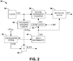
- FIG. 2 illustrates an example of a detection system 50.
- the detection system 50 can correspond to the detection system 26 in the example of FIG. 1 . Therefore, reference is to be made to the example of FIG. 1 in the following description of the example of FIG. 2 .
- the detection system 50 is configured to determine the rotation ROT of the NMR gyroscope system 10 based on an optical detection beam OPT DET that is provided from the vapor cell 12 that includes the alkali metal 14 and the first and second gyromagnetic isotopes 16 and 18.
- the detection system 50 includes a demodulation system 52 that is configured to receive the optical detection beam OPT DET and to demodulate the optical detection beam OPT DET to ascertain a precession frequency of the first gyromagnetic isotope 16 and a precession frequency of the second gyromagnetic isotope 18.
- the demodulation system 52 can, for example, demodulate the optical detection beam OPT DET by removing a carrier signal corresponding to the precession of the alkali metal 14 to provide the precession frequencies of the first and second gyromagnetic isotopes 16 and 18.
- the optical detection beam OPT DET can have a Faraday rotation that can correspond to a combined modulation of the effects of the precession of the first and second gyromagnetic isotopes 16 and 18, such that the demodulation system 52 can be configured to demodulate the optical detection beam OPT DET (e.g., via a bandpass filter) to ascertain the precession frequency of each of the first and second gyromagnetic isotopes 16 and 18.
- the demodulation system 52 can provide a frequency signal SUM that corresponds to a sum of the precession frequencies of the first and second gyromagnetic isotopes 16 and 18.
- the first and second gyromagnetic isotopes 16 and 18 can have been selected to counter-precess in the presence of the magnetic field B Z (e.g., the first and second gyromagnetic isotopes 16 and 18 can correspond to 131 Xe and 129 Xe). Therefore, the sum of the precession frequencies of the first and second gyromagnetic isotopes 16 and 18 can remain constant in response to rotation of the NMR gyroscope system 10 about the sensitive axis (e.g., in a constant magnitude of the magnetic field B Z ).
- the demodulation system 52 can be configured to provide a frequency signal I 1 R that corresponds to the precession frequency of the first gyromagnetic isotope 16 (e.g., 131 Xe) in the vapor cell 12. Therefore, the frequency signal I 1 R includes a first frequency component associated with the precession of the first gyromagnetic isotope 16 in free inertial space (i.e., in the presence of the magnetic field B Z ), and includes a second frequency component associated with the rotation of the NMR gyroscope system 10 about the sensitive axis.
- the measurement of the precession frequency of the first gyromagnetic isotope 16 based on the optical detection beam OPT DET thus cannot isolate the first and second frequency components with respect to each other.
- the detection system 50 also includes a clock 54, such as configured as a crystal clock, that generates a clock signal CLK.
- the clock signal CLK is provided to a digital reference counter 56 that is configured to implement a cyclical counter at a frequency corresponding to the first gyromagnetic isotope 16 in free inertial space (e.g., in the magnetic field B Z ) based on the clock signal CLK.
- the cyclical count value of the digital reference counter 56 is demonstrated in the example of FIG. 2 as a signal I 1 .
- the clock signal CLK is also provided to a precession reference counter 58 that is configured to generate a reference frequency SUM REF that can correspond to a sum of the precession frequencies of the first and second gyromagnetic isotopes 16 and 18 in free inertial space in the presence of the magnetic field B Z based on the predetermined constant ratio of the precession frequencies of the first and second gyromagnetic isotopes 16 and 18.
- the predetermined constant ratio of the precession frequencies of the first and second gyromagnetic isotopes 16 and 18 corresponds to a known ratio relationship between the Larmor precession frequencies of the first and second gyromagnetic isotopes 16 and 18 that is constant regardless of the magnitude of the magnetic field B Z , and thus stable to greater than an accuracy that may be required for the NMR gyroscope system 10.
- the predetermined constant ratio of the precession frequencies of the first and second gyromagnetic isotopes 16 and 18 can correspond to a ratio of the precession frequency of the first gyromagnetic isotope 16 and a sum (e.g., difference, depending on relative polarity of precession) of the precession frequencies of the first and second gyromagnetic isotopes 16 and 18.
- the accuracy of the Larmor frequency ratio of the first and second gyromagnetic isotopes 16 and 18 in a common magnetic field B Z allows the NMR gyroscope system 10 to achieve a very accurate determination of the rotation angle ROT about the sensitive axis based on the ratiometric mechanization described herein.
- the first gyromagnetic isotope 16 can correspond to 131 Xe and the second gyromagnetic isotope 18 can correspond to 129 Xe.
- a frequency f 1 can correspond to the Larmor precession frequency of the first gyromagnetic isotope 16 in free inertial space and a frequency f 1 m can correspond to the frequency f 1 minus the rotation of the NMR gyroscope system 10 about the sensitive axis.
- the frequency signal I 1 R corresponds to the frequency f 1 m.
- the frequency f 2 can correspond to the Larmor precession frequency of the second gyromagnetic isotope 18 in free inertial space and a frequency f 2 m can correspond to the frequency f 2 plus the rotation of the NMR gyroscope system 10 about the sensitive axis.
- Equation 1 can thus correspond to the predetermined constant ratio of the precession frequencies of the first and second gyromagnetic isotopes 16 and 18 that is implemented in the ratiometric implementation to determine the rotation of the NMR gyroscope system 10 about the sensitive axis. While the solution of Equation 1 is demonstrated as rounded to five places, it is to be understood that the ratio can be expressed at any resolution.
- the demodulation system 52 measures the precession frequencies of the first and second gyromagnetic isotopes 16 and 18 in the vapor cell 12, which includes the frequency of rotation of the NMR gyroscope system 10 about the sensitive axis. Therefore, the demodulation system 52 measures the frequencies f 1 m and f 2 m.
- the demodulation system 52 or an associated processor can be configured to multiply the frequencies f 1 m and f 2 m to calculate a sum and a difference of the frequencies f 1 m and f 2 m. The sum of the frequencies f 1 m and f 2 m can thus correspond to the frequency signal SUM that is provided by the demodulation system 52.
- the frequencies f 1 ' and f 2 ' can be generated by the precession reference counter 58 based on the clock signal CLK.
- the clock signal CLK has a frequency of approximately 6.0 MHz. However, it is to be understood that the clock signal CLK can have any frequency greater than or less than 6.0 MHz.
- the cyclical count value I 1 that is generated by the digital reference counter 56 based on the clock signal CLK corresponds to the frequency to the first gyromagnetic isotope 16 in free inertial space, and therefore increments at the frequency f 1 '.
- the digital reference counter 56 and the precession reference counter 58 can be configured as cyclical counters having respective values that cycle through 36,000 counts (i.e., from 0 through 35,999, such that a reset occurs at the 0 count).
- the cyclical counter value can be selected based on a desired resolution of the NMR gyroscope system 10.
- each increment of the digital reference counter 56 can thus correspond to 0.01° of rotation of the NMR gyroscope system 10 about the sensitive axis.
- the reference frequency SUM REF can correspond to a sum of the precession frequencies of the first and second gyromagnetic isotopes 16 and 18 in free inertial space in the presence of the magnetic field B Z .
- the reference frequency SUM REF corresponds to the frequency of 728.85 as demonstrated in Equation 6, such as counted down from the clock signal CLK.
- the detection system 50 also includes a phase-locked loop (PLL) component 60 that is configured to phase-lock the frequency signal SUM to the reference frequency SUM REF .
- PLL phase-locked loop
- the frequency signal SUM corresponds to the sum of the precession frequencies of the first and second gyromagnetic isotopes 16 and 18, which can remain constant in response to rotation of the NMR gyroscope system 10 about the sensitive axis (e.g., in a constant magnitude of the magnetic field B Z ) based on the counter-precession of the first and second gyromagnetic isotopes 16 and 18.
- the phase-locking of the frequency signal SUM to the reference frequency SUM REF can likewise be insensitive to rotation of the NMR gyroscope system 10 about the sensitive axis.
- the PLL component 60 can be configured to multiply the frequency signal SUM by a cosine of the reference frequency SUM REF .
- the PLL component 60 is demonstrated as generating a feedback signal B_FB.
- the feedback signal B_FB is provided to the magnetic field generator 20 to control the magnitude of the magnetic field B Z . Therefore, the magnetic field B Z can be maintained at a magnitude that can maintain the precession frequency of the first and second gyromagnetic isotopes 16 and 18, and thus the frequency signal SUM, substantially equal to the reference frequency SUM REF .
- the precession frequency f 1 of the first gyromagnetic isotope 16 can be set equal to the frequency f 1 ' generated by the precession reference counter 58.
- the frequency signal I 1 R can correspond to the precession of the first gyromagnetic isotope 16 in the vapor cell 12 (i.e., including a frequency component of the rotation of the NMR gyroscope system 10 about the sensitive axis). Accordingly, a frequency difference between the cyclical count value I 1 and the frequency signal I 1 R can correspond to rotation of the NMR gyroscope system 10 about the sensitive axis.
- the detection system 50 also includes an angle discriminator 62.
- the angle discriminator is configured to sample the frequency signal I 1 R that is provided from the demodulation system 52 at predetermined intervals.
- the frequency signal I 1 R corresponds to the precession frequency of the first gyromagnetic isotope 16 plus the rotation of the NMR gyroscope system 10 about the sensitive axis. Therefore, in the absence of rotation of the NMR gyroscope system 10 about the sensitive axis, the period of the frequency signal I 1 R is synchronized with a period of the cyclical count value I 1 that is generated by the digital reference counter 56 (e.g., 36,000 counts).
- the detection system 50 is configured to determine the rotation of the NMR gyroscope system 10 about the sensitive axis based on a difference of the number of counts of the cyclical count value I 1 in a given one sampling time to the next.
- the angle discriminator 62 can be configured to sample the frequency signal I 1 R at each period, and thus once for each period of the frequency signal I 1 R, or at each zero crossing, and thus twice for each period of the frequency signal I 1 R, such as to mitigate the effects of noise in the sampling of the frequency signal I 1 R.
- the detection system 50 further includes a synchronization latch 64, demonstrated in the example of FIG. 2 as SYNC LATCH, and a rotation latch 66.
- the synchronization latch 64 is configured to synchronize the period of the frequency signal I 1 R and the cyclical count value I 1 at initialization of the detection system 50.
- the angle discriminator 62 is configured to generate a trigger signal TRG upon a sampling time (e.g., zero-crossing) of the frequency signal I 1 R.
- the trigger signal TRG is provided to both the synchronization latch 64 and the rotation latch 66.
- an initialization signal INIT can be provided to the synchronization latch 64.
- the synchronization latch 64 can provide a reset signal RST to the digital reference counter 56 to reset the cyclical count value I 1 .
- the cyclical count value I 1 can be synchronized with the period of the frequency signal I 1 R to allow detection of the rotation of the NMR gyroscope system 10 about the sensitive axis based on changes of the period of the frequency signal I 1 R relative to the cyclical count value I 1 .
- the trigger signal TRG can be provided to the rotation latch 66 to latch a value of the cyclical count value I 1 .
- the latched value of the cyclical count value I 1 can be provided to a processor (not shown), such as via a bus, as the signal ROT corresponding to the rotation of the NMR gyroscope system 10 about the sensitive axis.
- any non-zero value of the signal ROT can correspond to rotation of the NMR gyroscope system 10, such as based on the precision of the digital reference counter 56 (e.g., each increment being equal to 0.01° of rotation of the NMR gyroscope system 10 about the sensitive axis, as described previously).
- the trigger signal TRG is provided to the rotation latch 66 to capture the cyclical count value I 1
- any change in the value of the captured cyclical count value ROT corresponds to additional rotation of the NMR gyroscope system 10 about the sensitive axis.
- the associated processor can thus calculate an angle of rotation, a rate of rotation, or any other inertial statistics of the NMR gyroscope system 10 based on the captured cyclical count value ROT.
- the NMR gyroscope system 10 and the associated detection system 50 are therefore demonstrated herein as a manner of determining rotation about a sensitive axis based on the highly stable ratio of the precession of gyromagnetic isotopes in the presence of a magnetic field.
- the NMR gyroscope system 10 can be implemented in a simple but highly accurate manner relative to typical gyroscope systems to calculate rotation about a sensitive axis.
- the detection system 50 can be substantially insensitive to clock drift (e.g., to first order).
- the magnetic field B Z is controlled based on the phase-locking of the signal SUM to the reference frequency SUM REF , the detection system 50 can likewise be substantially insensitive to magnetic field drift. Accordingly, the NMR gyroscope system 10 can be implemented to accurately determine rotation of the NMR gyroscope system 10 about a sensitive axis in a simplistic manner.
- FIG. 3 illustrates an example of a three-axis gyroscope system 100 in accordance with an aspect of the invention.
- the three-axis gyroscope system 100 can be implemented in any of a variety of navigation control systems, such as for aircraft and/or spacecraft, or device to monitor yaw, pitch, and roll rotational motion information.
- the three-axis gyroscope system 100 includes an X-axis gyroscope system 102, a Y-axis gyroscope system 104, and a Z-axis gyroscope system 106.
- the X-axis gyroscope system 102 can have a sensitive axis about the X-axis
- the Y-axis gyroscope system 104 can have a sensitive axis about the Y-axis
- the Z-axis gyroscope system 106 can have a sensitive axis about the Z-axis.
- each of the X-axis, Y-axis, and Z-axis gyroscope systems 102, 104, and 106 can be configured substantially similar to the NMR gyroscope system 10 in the example of FIG. 1 .
- each of X-axis, Y-axis, and Z-axis gyroscope systems 102, 104, and 106 can be configured to determine respective rotation angles ROT X , ROT Y , and ROT Z about each of the respective X, Y, and Z axes based on respective detection beams OPT DET that are provided through each of the respective vapor cells 108, 110, and 112 and based on a predetermined constant ratio of precession frequencies of two gyromagnetic isotopes (e.g., 131 Xe and 129 Xe).
- each of the X-axis, Y-axis, and Z-axis gyroscope systems 102, 104, and 106 can include a detection system configured substantially similar to the detection system 50 in the example of FIG. 2 .
- each of the X-axis, Y-axis, and Z-axis gyroscope systems 102, 104, and 106 are demonstrated as outputting signals that include the respective rotation angles ROT X , ROT Y , and ROT Z to a motion sensor 116.
- the motion sensor 116 can thus be configured as a processor to determine an aggregate three-axis rotational motion of the associated vehicle or device that includes the three-axis gyroscope system 100. Therefore, the yaw, pitch, and roll of the associated vehicle or device that includes the three-axis gyroscope system 100 can be determined. Accordingly, the motion sensor 116 can be configured to display, output, and/or report the three-axis rotational motion of the associated vehicle or device that includes the three-axis gyroscope system 100.
- FIG. 4 a methodology in accordance with various aspects of the present invention will be better appreciated with reference to FIG. 4 . While, for purposes of simplicity of explanation, the methodology of FIG. 4 is shown and described as executing serially, it is to be understood and appreciated that the present invention is not limited by the illustrated order, as some aspects could, in accordance with the present invention, occur in different orders and/or concurrently with other aspects from that shown and described herein. Moreover, not all illustrated features may be required to implement a methodology in accordance with an aspect of the present invention.
- FIG. 4 illustrates an example of a method 150 for measuring a rotation about a sensitive axis of an NMR gyroscope system (e.g., the NMR gyroscope system 10).
- an optical pump beam e.g., the optical pump beam OPT PMP
- a pump laser e.g., the pump laser 22
- a magnetic field e.g., the magnetic field Bz
- a magnetic field generator e.g., the magnetic field generator 20.
- the optical pump beam and the magnetic field are provided through a vapor cell (e.g., the vapor cell 12) comprising an alkali metal (e.g., the alkali metal 14), a first gyromagnetic isotope (e.g., the first gyromagnetic isotope 16), and a second gyromagnetic isotope (e.g., the second gyromagnetic isotope 18) to cause the first and second gyromagnetic isotopes to counter-precess.
- an optical probe beam e.g., the optical probe beam OPT PRB
- a probe laser e.g., the probe laser 24
- the optical probe beam is provided through the vapor cell orthogonally with respect to the optical pump beam to provide a detection beam (e.g., the detection beam OPT DET ) exiting the vapor cell.
- the detection beam is demodulated to determine a precession of the first and second gyromagnetic isotopes.
- a reference frequency e.g., the reference frequency SUM REF
- a frequency e.g., the frequency signal SUM associated with the precession of the first and second gyromagnetic isotopes is phase-locked to the reference frequency.
- a rotation about the sensitive axis is determined based on the frequency of the precession of one of the first and second gyromagnetic isotopes based on the phase-locked frequency of the precession of the first and second gyromagnetic isotopes.
Landscapes
- Physics & Mathematics (AREA)
- General Physics & Mathematics (AREA)
- Engineering & Computer Science (AREA)
- Radar, Positioning & Navigation (AREA)
- Remote Sensing (AREA)
- Condensed Matter Physics & Semiconductors (AREA)
- Gyroscopes (AREA)
Claims (9)
- Kernmagnetresonanz- (NMR) Gyroskopsystem (10) mit:einer Dampfzelle (12), die ein Alkalimetall (14), ein erstes gyromagnetisches Isotop (16) und ein zweites gyromagnetisches Isotop (18) aufweist;einem Pumplaser (22), der konfiguriert ist zum Erzeugen eines optischen Pumpstrahls (OPTPMP);einem Magnetfeldgenerator (20), der konfiguriert ist zum Erzeugen eines Magnetfelds (Bz), das im Wesentlichen mit einer empfindlichen Achse ausgerichtet ist, um eine Gegenpräzession des ersten und des zweiten gyromagnetischen Isotops (16, 18) basierend auf dem optischen Pumpstrahl (OPTPMP) und dem Alkalimetall (14) zu bewirken;einem Sondenlaser (24), der konfiguriert ist zum Bereitstellen eines optischen Sondenstrahls (OPTPRB) durch die Dampfzelle (12), der als ein Detektionsstrahl (OPTDET) aus der Dampfzelle (12) austritt; undeinem Detektionssystem (26, 50), das konfiguriert ist zum Überwachen des Detektionsstrahls (OPTDET), zum Erzeugen einer Referenzfrequenz (SUMREF) basierend auf einem vorbestimmten konstanten Verhältnis der Präzessionsfrequenzen des ersten und des zweiten gyromagnetischen Isotops (16, 18) und zum Bestimmen einer Drehung (ROT) des NMR-Gyroskopsystems (10) um die empfindliche Achse herum, wobei das Detektionssystem (26, 50) aufweist:ein Demodulationssystem (52), das konfiguriert ist zum Demodulieren des Detektionsstrahls (OPTDET) und zum Bereitstellen eines ersten Frequenzsignals, das der Präzession des ersten gyromagnetischen Isotops (16) in der Dampfzelle (12) basierend auf dem Magnetfeld (Bz) entspricht;einen digitalen Referenzzähler (56), der konfiguriert ist zum Erzeugen einer zweiten Frequenz, die der Präzession des ersten gyromagnetischen Isotops (16) im freien Inertialraum in dem Magnetfeld (Bz) basierend auf einem Taktsignal (CLK) entspricht, und zum Bereitstellen der zweiten Frequenz als einen Zählwert;einen Dreh-Latch (66), der konfiguriert ist zum Erfassen des Zählwerts als Reaktion auf das Auslösesignal (TRG);einen Winkeldiskriminator (62), der konfiguriert ist zum Abtasten des ersten Frequenzsignals zu vorbestimmten Abtastzeiten, die mit dem ersten Frequenzsignal assoziiert sind, und zum Bereitstellen des Auslösesignals (TRG) an den Dreh-Latch (66) zu jeder der vorbestimmten Abtastzeiten; undeinen Phasenregelkreis, der konfiguriert ist zum Phasenregeln einer Summe der Präzessionsfrequenzen des ersten und des zweiten gyromagnetischen Isotops (16, 18) mit der Referenzfrequenz (SUMREF), wobei das Detektionssystem (26, 50) konfiguriert ist zum Bestimmen der Drehung (ROT) des NMR-Gyroskopsystems (10) um die empfindliche Achse herum, basierend auf einem Vergleich des erfassen Zählwerts mit einem unmittelbar vorausgehenden erfassten Zählwert.
- System (10) nach Anspruch 1, wobei das Detektionssystem (26, 50) konfiguriert ist zum Erzeugen der Referenzfrequenz (SUMREF) basierend auf dem digitalen Referenzzähler (56), der eine mit dem Taktsignal (CLK) assoziierte Frequenz aufweist, die durch ein vorbestimmtes konstantes Verhältnis einer Präzessionsfrequenz des ersten gyromagnetischen Isotops (16) zu einer Summe von Präzessionsfrequenzen des ersten und des zweiten gyromagnetischen Isotops (16, 18) dividiert wird.
- System (10) nach Anspruch 1, wobei das Detektionssystem (26, 50) aufweist:
einen Präzessionsreferenzzähler (58), der konfiguriert ist zum Erzeugen einer Referenzfrequenz (SUMREF) basierend auf dem Taktsignal (CLK) und basierend auf dem vorbestimmten konstanten Verhältnis der Präzessionsfrequenzen des ersten und des zweiten gyromagnetischen Isotops (16, 18). - System (10) nach Anspruch 3, wobei der Phasenregelkreis konfiguriert ist zum Erzeugen eines Magnetfeld-Rückkopplungssignals (B_FB) basierend auf der Phasenregelung der Summe von Präzessionsfrequenzen der ersten und der zweiten gyromagnetischen Isotope (16, 18) mit der Referenzfrequenz (SUMREF), wobei das Magnetfeld-Rückkopplungssignal (B_FB) dem Magnetfeld-Rückkopplungssignal (B_FB) zum Einstellen einer Größe des Magnetfelds bereitgestellt wird.
- System (10) nach Anspruch 1, wobei das Detektionssystem (50) konfiguriert ist zum Zurücksetzen des Zählwerts, um den Zählwert mit der Periode der ersten Frequenz zu einer vorbestimmten Abtastzeit als Reaktion auf ein Initialisierungssignal (INIT) zu synchronisieren.
- Dreiachsiges NMR-Gyroskopsystem (100) mit einer Vielzahl von NMR-Gyroskopsystemen (10) nach Anspruch 1, das konfiguriert ist zum Bestimmen einer Drehung (ROT) des dreiachsigen NMR-Gyroskopsystems (100) um jede der drei orthogonalen empfindlichen Achsen herum.
- Verfahren (150) zum Messen einer Drehung (ROT) um eine empfindliche Achse eines Kernmagnetresonanz- (NMR) Gyroskopsystems (10) herum, wobei das Verfahren umfasst:Erzeugen (152) eines optischen Pumpstrahls (OPTPMP) über einen Pumplaser (22);Erzeugen (154) eines Magnetfelds (Bz) über einen Magnetfeldgenerator (20);Bereitstellen (156) des optischen Pumpstrahls (OPTPMP) und des Magnetfelds (Bz) durch eine Dampfzelle (12), die ein Alkalimetall (14), ein erstes gyromagnetisches Isotop (16) und ein zweites gyromagnetisches Isotop (18) aufweist, um eine Gegenpräzession des ersten und des zweiten gyromagnetischen Isotops (16, 18) zu bewirken;Erzeugen (158) eines optische Sondenstrahls (OPTPRB) über einen Sondenlaser;Bereitstellen (160) des optischen Sondenstrahls durch die Dampfzelle (12) in einer Richtung orthogonal relativ zu dem optischen Pumpstrahl (OPTPMP), um einen aus der Dampfzelle (12) austretenden Detektionsstrahl (OPTDET) bereitzustellen;Demodulieren (162) des Detektionsstrahls (OPTDET), um eine Präzessionsfrequenz des ersten und des zweiten gyromagnetisches Isotops (16, 18) zu bestimmen, wobei das Demodulieren des Detektionsstrahls (OPTDET) umfasst:Bereitstellen eines ersten Frequenzsignals, das der Präzession des ersten gyromagnetischen Isotops (16) in der Dampfzelle (12) basierend auf dem Magnetfeld (Bz) entspricht; undErzeugen einer zweiten Frequenz, die der Präzession des ersten gyromagnetischen Isotops (16) in dem freien Inertialraum in dem Magnetfeld (Bz) basierend auf einem Taktsignal (CLK) entspricht;Erzeugen (164) einer Referenzfrequenz (SUMREF) basierend auf einem vorbestimmten konstanten Verhältnis der Präzessionsfrequenzen des ersten und des zweiten gyromagnetischen Isotops (16, 18);Phasenregelung (166) einer Summe von Präzessionsfrequenzen des ersten und des zweiten gyromagnetischen Isotops (16, 18) zu der Referenzfrequenz (SUMREF) ;Bestimmen (168) einer Drehung (ROT) des NMR-Gyroskopsystems (10) um die empfindliche Achse herum, wobei das Bestimmen (168) der Drehung (ROT) des NMR-Gyroskopsystems (10) umfasst:Bereitstellen einer zweiten Frequenz als einen Zählwert;Erzeugen eines Auslösesignals (TRG) zu jeder der vorbestimmten Abtastzeiten, die mit dem ersten Frequenzsignal assoziiert sind; undLatchen des Zählwerts als Reaktion auf das Auslösesignal (TRG), wobei das Bestimmen der Drehung (ROT) des NMR-Gyroskopsystems (10) um die empfindliche Achse herum das Vergleichen des gelatchten Zählwerts mit einem unmittelbar vorausgehenden gelachten Zählwert umfasst.
- Verfahren nach Anspruch 7, wobei das Erzeugen (164) der Referenzfrequenz (SUMREF) das Erzeugen der Referenzfrequenz (SUMREF) basierend auf einer mit einem Taktsignal (CLK) assoziierten Zählfrequenz umfasst, die durch ein vorbestimmtes konstantes Verhältnis einer Präzessionsfrequenz des ersten gyromagnetischen Isotops (16) zu einer Summe von Präzessionsfrequenzen des ersten und des zweiten gyromagnetischen Isotops (16, 18) dividiert wird.
- Verfahren nach Anspruch 7, ferner umfassend:Erzeugen eines Magnetfeld-Rückkopplungssignals (B_FB) basierend auf der Phasenregelung der Summe von Präzessionsfrequenzen des ersten und des zweiten gyromagnetischen Isotops (16, 18) zu der Referenzfrequenz (SUMREF); undEinstellen einer Größe des Magnetfelds (Bz) basierend auf dem Magnetfeld-Rückkopplungssignal (B_FB).
Applications Claiming Priority (1)
| Application Number | Priority Date | Filing Date | Title |
|---|---|---|---|
| US14/593,827 US9778041B2 (en) | 2015-01-09 | 2015-01-09 | Ratiometric nuclear magnetic resonance (NMR) gyroscope system |
Publications (2)
| Publication Number | Publication Date |
|---|---|
| EP3043147A1 EP3043147A1 (de) | 2016-07-13 |
| EP3043147B1 true EP3043147B1 (de) | 2020-04-22 |
Family
ID=55070920
Family Applications (1)
| Application Number | Title | Priority Date | Filing Date |
|---|---|---|---|
| EP16150518.5A Active EP3043147B1 (de) | 2015-01-09 | 2016-01-08 | Ratiometrisches nuklearmagnetkernresonanzgyroskop |
Country Status (3)
| Country | Link |
|---|---|
| US (1) | US9778041B2 (de) |
| EP (1) | EP3043147B1 (de) |
| JP (1) | JP6363631B2 (de) |
Families Citing this family (13)
| Publication number | Priority date | Publication date | Assignee | Title |
|---|---|---|---|---|
| US9645205B2 (en) * | 2012-12-11 | 2017-05-09 | Northrop Grumman Guidance And Electronics Company, Inc. | Combined electron paramagnetic resonance (EPR) and nuclear magnetic resonance (NMR) magnetometer system |
| US9618362B2 (en) * | 2014-06-03 | 2017-04-11 | Northrop Grumman Systems Corporation | Self-calibrating nuclear magnetic resonance (NMR) gyroscope system |
| US9778041B2 (en) * | 2015-01-09 | 2017-10-03 | Northrop Grumman Systems Corporation | Ratiometric nuclear magnetic resonance (NMR) gyroscope system |
| KR101698693B1 (ko) | 2015-12-24 | 2017-01-20 | 말레 인터내셔널 게엠베하 | 손잡이가 달린 드레인핀을 구비하는 오일필터모듈 |
| CN107422287B (zh) * | 2017-04-21 | 2019-08-23 | 东南大学 | 一种多同位素磁共振信号同步激励与探测方法及装置 |
| US10782368B2 (en) | 2017-05-31 | 2020-09-22 | Northrop Grumman Systems Corporation | Pulsed-beam atomic magnetometer system |
| CN107845951A (zh) * | 2017-11-20 | 2018-03-27 | 北京航天控制仪器研究所 | 用于核磁共振陀螺仪的激光频率功率双稳定系统和方法 |
| US11133117B2 (en) | 2019-05-08 | 2021-09-28 | Northrop Grumman Systems Corporation | Atomic interferometer system |
| AU2020387361B2 (en) * | 2019-08-30 | 2025-06-26 | Northrop Grumman Systems Corporation | Vector-sensitive electrometer |
| DE102019220363A1 (de) * | 2019-12-20 | 2021-06-24 | Robert Bosch Gesellschaft mit beschränkter Haftung | Verfahren zur Ermittlung einer Änderung einer rotatorischen Orientierung im Raum eines NMR-Gyroskops und NMR-Gyroskop |
| US12032009B2 (en) * | 2020-06-26 | 2024-07-09 | Honeywell International Inc. | Wideband RF spectrum real-time monitor |
| EP4264294B1 (de) | 2020-12-17 | 2025-07-09 | Northrop Grumman Systems Corporation | Elektrometer mit rydberg-frequenzabstimmung |
| DE102024206754A1 (de) * | 2024-07-18 | 2026-01-22 | Robert Bosch Gesellschaft mit beschränkter Haftung | Auswertevorrichtung für ein NMR-Gyroskop, NMR-Gyroskop und Verfahren zu Auswertung eines Signals in einem NMR-Gyroskop |
Family Cites Families (7)
| Publication number | Priority date | Publication date | Assignee | Title |
|---|---|---|---|---|
| US4157495A (en) | 1976-08-14 | 1979-06-05 | Litton Systems, Inc. | Nuclear magnetic resonance gyro |
| US8159220B2 (en) * | 2009-08-03 | 2012-04-17 | Northrop Grumman Guidance And Electronics Company, Inc. | Nuclear magnetic resonance gyroscope mechanization |
| US8600691B2 (en) * | 2011-01-21 | 2013-12-03 | Northrop Grumman Guidance and Electronics, Inc. | Gyroscope system magnetic field error compensation |
| US9062973B2 (en) | 2011-01-31 | 2015-06-23 | Northrop Grumman Guidance And Electronics Company, Inc. | Atom beam gyroscope |
| US9645205B2 (en) * | 2012-12-11 | 2017-05-09 | Northrop Grumman Guidance And Electronics Company, Inc. | Combined electron paramagnetic resonance (EPR) and nuclear magnetic resonance (NMR) magnetometer system |
| US9229073B2 (en) * | 2012-12-27 | 2016-01-05 | Northrop Grumman Guidance And Electronics Company, Inc. | Systems and method to substantially mitigate AC stark shift effects in a sensor system |
| US9778041B2 (en) * | 2015-01-09 | 2017-10-03 | Northrop Grumman Systems Corporation | Ratiometric nuclear magnetic resonance (NMR) gyroscope system |
-
2015
- 2015-01-09 US US14/593,827 patent/US9778041B2/en active Active
-
2016
- 2016-01-08 EP EP16150518.5A patent/EP3043147B1/de active Active
- 2016-01-08 JP JP2016002435A patent/JP6363631B2/ja active Active
Non-Patent Citations (1)
| Title |
|---|
| None * |
Also Published As
| Publication number | Publication date |
|---|---|
| JP6363631B2 (ja) | 2018-07-25 |
| EP3043147A1 (de) | 2016-07-13 |
| US20160202062A1 (en) | 2016-07-14 |
| US9778041B2 (en) | 2017-10-03 |
| JP2016128817A (ja) | 2016-07-14 |
Similar Documents
| Publication | Publication Date | Title |
|---|---|---|
| EP3043147B1 (de) | Ratiometrisches nuklearmagnetkernresonanzgyroskop | |
| EP2952854B1 (de) | Selbstkalibrierendes magnetisches kernresonanz (nmr)-gyroskopsystem | |
| US8159220B2 (en) | Nuclear magnetic resonance gyroscope mechanization | |
| EP2666037B1 (de) | Magnetfeldfehlerkompensation für ein gyroskopsystem | |
| EP3336586B1 (de) | Atomstrahlgyroskop | |
| Chupp et al. | Results of a new test of local Lorentz invariance: A search for mass anisotropy in Ne 21 | |
| JP6062977B2 (ja) | 核磁気共鳴ジャイロスコープシステム | |
| US4157495A (en) | Nuclear magnetic resonance gyro | |
| US7728587B2 (en) | Self-calibrating nuclear magnetic resonance gyro | |
| EP2743715A1 (de) | Kombiniertes paramagnetisches Elektronenresonanz (EPR) und Kernspinresonanz (NMR) Magnetometersystem | |
| CN106017451A (zh) | 一种基于serf原子器件的磁场补偿惯性角速率的高精度测量方法 | |
| EP2952855B1 (de) | Stabilisierung von optischem sondenstrahl in einem atomsensorsystem | |
| US8698493B2 (en) | Noble gas magnetic resonator | |
| US20210293543A1 (en) | Apparatus and Method for Integrating Continuous and Discontinuous Inertial Instrument | |
| RU201524U1 (ru) | Квантовый гироскоп | |
| Qiang et al. | Design and Experiment of Transverse Driving Oscillator for Nuclear Magnetic Resonance Gyroscopes | |
| Li et al. | Modeling of magnetic fields for application in nuclear magnetic resonance gyroscopes |
Legal Events
| Date | Code | Title | Description |
|---|---|---|---|
| PUAI | Public reference made under article 153(3) epc to a published international application that has entered the european phase |
Free format text: ORIGINAL CODE: 0009012 |
|
| AK | Designated contracting states |
Kind code of ref document: A1 Designated state(s): AL AT BE BG CH CY CZ DE DK EE ES FI FR GB GR HR HU IE IS IT LI LT LU LV MC MK MT NL NO PL PT RO RS SE SI SK SM TR |
|
| AX | Request for extension of the european patent |
Extension state: BA ME |
|
| STAA | Information on the status of an ep patent application or granted ep patent |
Free format text: STATUS: REQUEST FOR EXAMINATION WAS MADE |
|
| 17P | Request for examination filed |
Effective date: 20170113 |
|
| RBV | Designated contracting states (corrected) |
Designated state(s): AL AT BE BG CH CY CZ DE DK EE ES FI FR GB GR HR HU IE IS IT LI LT LU LV MC MK MT NL NO PL PT RO RS SE SI SK SM TR |
|
| STAA | Information on the status of an ep patent application or granted ep patent |
Free format text: STATUS: EXAMINATION IS IN PROGRESS |
|
| 17Q | First examination report despatched |
Effective date: 20171207 |
|
| GRAJ | Information related to disapproval of communication of intention to grant by the applicant or resumption of examination proceedings by the epo deleted |
Free format text: ORIGINAL CODE: EPIDOSDIGR1 |
|
| GRAP | Despatch of communication of intention to grant a patent |
Free format text: ORIGINAL CODE: EPIDOSNIGR1 |
|
| GRAP | Despatch of communication of intention to grant a patent |
Free format text: ORIGINAL CODE: EPIDOSNIGR1 |
|
| STAA | Information on the status of an ep patent application or granted ep patent |
Free format text: STATUS: GRANT OF PATENT IS INTENDED |
|
| INTG | Intention to grant announced |
Effective date: 20191126 |
|
| RIN1 | Information on inventor provided before grant (corrected) |
Inventor name: GRIFFITH, ROBERT C. |
|
| GRAS | Grant fee paid |
Free format text: ORIGINAL CODE: EPIDOSNIGR3 |
|
| GRAA | (expected) grant |
Free format text: ORIGINAL CODE: 0009210 |
|
| STAA | Information on the status of an ep patent application or granted ep patent |
Free format text: STATUS: THE PATENT HAS BEEN GRANTED |
|
| AK | Designated contracting states |
Kind code of ref document: B1 Designated state(s): AL AT BE BG CH CY CZ DE DK EE ES FI FR GB GR HR HU IE IS IT LI LT LU LV MC MK MT NL NO PL PT RO RS SE SI SK SM TR |
|
| REG | Reference to a national code |
Ref country code: CH Ref legal event code: EP |
|
| REG | Reference to a national code |
Ref country code: IE Ref legal event code: FG4D |
|
| REG | Reference to a national code |
Ref country code: DE Ref legal event code: R096 Ref document number: 602016034340 Country of ref document: DE |
|
| REG | Reference to a national code |
Ref country code: AT Ref legal event code: REF Ref document number: 1260711 Country of ref document: AT Kind code of ref document: T Effective date: 20200515 |
|
| REG | Reference to a national code |
Ref country code: LT Ref legal event code: MG4D |
|
| REG | Reference to a national code |
Ref country code: NL Ref legal event code: MP Effective date: 20200422 |
|
| PG25 | Lapsed in a contracting state [announced via postgrant information from national office to epo] |
Ref country code: LT Free format text: LAPSE BECAUSE OF FAILURE TO SUBMIT A TRANSLATION OF THE DESCRIPTION OR TO PAY THE FEE WITHIN THE PRESCRIBED TIME-LIMIT Effective date: 20200422 Ref country code: NL Free format text: LAPSE BECAUSE OF FAILURE TO SUBMIT A TRANSLATION OF THE DESCRIPTION OR TO PAY THE FEE WITHIN THE PRESCRIBED TIME-LIMIT Effective date: 20200422 Ref country code: GR Free format text: LAPSE BECAUSE OF FAILURE TO SUBMIT A TRANSLATION OF THE DESCRIPTION OR TO PAY THE FEE WITHIN THE PRESCRIBED TIME-LIMIT Effective date: 20200723 Ref country code: NO Free format text: LAPSE BECAUSE OF FAILURE TO SUBMIT A TRANSLATION OF THE DESCRIPTION OR TO PAY THE FEE WITHIN THE PRESCRIBED TIME-LIMIT Effective date: 20200722 Ref country code: PT Free format text: LAPSE BECAUSE OF FAILURE TO SUBMIT A TRANSLATION OF THE DESCRIPTION OR TO PAY THE FEE WITHIN THE PRESCRIBED TIME-LIMIT Effective date: 20200824 Ref country code: FI Free format text: LAPSE BECAUSE OF FAILURE TO SUBMIT A TRANSLATION OF THE DESCRIPTION OR TO PAY THE FEE WITHIN THE PRESCRIBED TIME-LIMIT Effective date: 20200422 Ref country code: IS Free format text: LAPSE BECAUSE OF FAILURE TO SUBMIT A TRANSLATION OF THE DESCRIPTION OR TO PAY THE FEE WITHIN THE PRESCRIBED TIME-LIMIT Effective date: 20200822 Ref country code: SE Free format text: LAPSE BECAUSE OF FAILURE TO SUBMIT A TRANSLATION OF THE DESCRIPTION OR TO PAY THE FEE WITHIN THE PRESCRIBED TIME-LIMIT Effective date: 20200422 |
|
| REG | Reference to a national code |
Ref country code: AT Ref legal event code: MK05 Ref document number: 1260711 Country of ref document: AT Kind code of ref document: T Effective date: 20200422 |
|
| PG25 | Lapsed in a contracting state [announced via postgrant information from national office to epo] |
Ref country code: LV Free format text: LAPSE BECAUSE OF FAILURE TO SUBMIT A TRANSLATION OF THE DESCRIPTION OR TO PAY THE FEE WITHIN THE PRESCRIBED TIME-LIMIT Effective date: 20200422 Ref country code: HR Free format text: LAPSE BECAUSE OF FAILURE TO SUBMIT A TRANSLATION OF THE DESCRIPTION OR TO PAY THE FEE WITHIN THE PRESCRIBED TIME-LIMIT Effective date: 20200422 Ref country code: RS Free format text: LAPSE BECAUSE OF FAILURE TO SUBMIT A TRANSLATION OF THE DESCRIPTION OR TO PAY THE FEE WITHIN THE PRESCRIBED TIME-LIMIT Effective date: 20200422 Ref country code: BG Free format text: LAPSE BECAUSE OF FAILURE TO SUBMIT A TRANSLATION OF THE DESCRIPTION OR TO PAY THE FEE WITHIN THE PRESCRIBED TIME-LIMIT Effective date: 20200722 |
|
| PG25 | Lapsed in a contracting state [announced via postgrant information from national office to epo] |
Ref country code: AL Free format text: LAPSE BECAUSE OF FAILURE TO SUBMIT A TRANSLATION OF THE DESCRIPTION OR TO PAY THE FEE WITHIN THE PRESCRIBED TIME-LIMIT Effective date: 20200422 |
|
| REG | Reference to a national code |
Ref country code: DE Ref legal event code: R097 Ref document number: 602016034340 Country of ref document: DE |
|
| PG25 | Lapsed in a contracting state [announced via postgrant information from national office to epo] |
Ref country code: ES Free format text: LAPSE BECAUSE OF FAILURE TO SUBMIT A TRANSLATION OF THE DESCRIPTION OR TO PAY THE FEE WITHIN THE PRESCRIBED TIME-LIMIT Effective date: 20200422 Ref country code: RO Free format text: LAPSE BECAUSE OF FAILURE TO SUBMIT A TRANSLATION OF THE DESCRIPTION OR TO PAY THE FEE WITHIN THE PRESCRIBED TIME-LIMIT Effective date: 20200422 Ref country code: CZ Free format text: LAPSE BECAUSE OF FAILURE TO SUBMIT A TRANSLATION OF THE DESCRIPTION OR TO PAY THE FEE WITHIN THE PRESCRIBED TIME-LIMIT Effective date: 20200422 Ref country code: DK Free format text: LAPSE BECAUSE OF FAILURE TO SUBMIT A TRANSLATION OF THE DESCRIPTION OR TO PAY THE FEE WITHIN THE PRESCRIBED TIME-LIMIT Effective date: 20200422 Ref country code: AT Free format text: LAPSE BECAUSE OF FAILURE TO SUBMIT A TRANSLATION OF THE DESCRIPTION OR TO PAY THE FEE WITHIN THE PRESCRIBED TIME-LIMIT Effective date: 20200422 Ref country code: EE Free format text: LAPSE BECAUSE OF FAILURE TO SUBMIT A TRANSLATION OF THE DESCRIPTION OR TO PAY THE FEE WITHIN THE PRESCRIBED TIME-LIMIT Effective date: 20200422 Ref country code: SM Free format text: LAPSE BECAUSE OF FAILURE TO SUBMIT A TRANSLATION OF THE DESCRIPTION OR TO PAY THE FEE WITHIN THE PRESCRIBED TIME-LIMIT Effective date: 20200422 |
|
| PG25 | Lapsed in a contracting state [announced via postgrant information from national office to epo] |
Ref country code: SK Free format text: LAPSE BECAUSE OF FAILURE TO SUBMIT A TRANSLATION OF THE DESCRIPTION OR TO PAY THE FEE WITHIN THE PRESCRIBED TIME-LIMIT Effective date: 20200422 Ref country code: PL Free format text: LAPSE BECAUSE OF FAILURE TO SUBMIT A TRANSLATION OF THE DESCRIPTION OR TO PAY THE FEE WITHIN THE PRESCRIBED TIME-LIMIT Effective date: 20200422 |
|
| PLBE | No opposition filed within time limit |
Free format text: ORIGINAL CODE: 0009261 |
|
| STAA | Information on the status of an ep patent application or granted ep patent |
Free format text: STATUS: NO OPPOSITION FILED WITHIN TIME LIMIT |
|
| 26N | No opposition filed |
Effective date: 20210125 |
|
| PG25 | Lapsed in a contracting state [announced via postgrant information from national office to epo] |
Ref country code: SI Free format text: LAPSE BECAUSE OF FAILURE TO SUBMIT A TRANSLATION OF THE DESCRIPTION OR TO PAY THE FEE WITHIN THE PRESCRIBED TIME-LIMIT Effective date: 20200422 |
|
| PG25 | Lapsed in a contracting state [announced via postgrant information from national office to epo] |
Ref country code: MC Free format text: LAPSE BECAUSE OF FAILURE TO SUBMIT A TRANSLATION OF THE DESCRIPTION OR TO PAY THE FEE WITHIN THE PRESCRIBED TIME-LIMIT Effective date: 20200422 |
|
| REG | Reference to a national code |
Ref country code: CH Ref legal event code: PL |
|
| PG25 | Lapsed in a contracting state [announced via postgrant information from national office to epo] |
Ref country code: LU Free format text: LAPSE BECAUSE OF NON-PAYMENT OF DUE FEES Effective date: 20210108 |
|
| REG | Reference to a national code |
Ref country code: BE Ref legal event code: MM Effective date: 20210131 |
|
| PG25 | Lapsed in a contracting state [announced via postgrant information from national office to epo] |
Ref country code: CH Free format text: LAPSE BECAUSE OF NON-PAYMENT OF DUE FEES Effective date: 20210131 Ref country code: LI Free format text: LAPSE BECAUSE OF NON-PAYMENT OF DUE FEES Effective date: 20210131 |
|
| PG25 | Lapsed in a contracting state [announced via postgrant information from national office to epo] |
Ref country code: IE Free format text: LAPSE BECAUSE OF NON-PAYMENT OF DUE FEES Effective date: 20210108 |
|
| PG25 | Lapsed in a contracting state [announced via postgrant information from national office to epo] |
Ref country code: BE Free format text: LAPSE BECAUSE OF NON-PAYMENT OF DUE FEES Effective date: 20210131 |
|
| PG25 | Lapsed in a contracting state [announced via postgrant information from national office to epo] |
Ref country code: HU Free format text: LAPSE BECAUSE OF FAILURE TO SUBMIT A TRANSLATION OF THE DESCRIPTION OR TO PAY THE FEE WITHIN THE PRESCRIBED TIME-LIMIT; INVALID AB INITIO Effective date: 20160108 |
|
| PG25 | Lapsed in a contracting state [announced via postgrant information from national office to epo] |
Ref country code: CY Free format text: LAPSE BECAUSE OF FAILURE TO SUBMIT A TRANSLATION OF THE DESCRIPTION OR TO PAY THE FEE WITHIN THE PRESCRIBED TIME-LIMIT Effective date: 20200422 |
|
| P01 | Opt-out of the competence of the unified patent court (upc) registered |
Effective date: 20230607 |
|
| PG25 | Lapsed in a contracting state [announced via postgrant information from national office to epo] |
Ref country code: MK Free format text: LAPSE BECAUSE OF FAILURE TO SUBMIT A TRANSLATION OF THE DESCRIPTION OR TO PAY THE FEE WITHIN THE PRESCRIBED TIME-LIMIT Effective date: 20200422 |
|
| PG25 | Lapsed in a contracting state [announced via postgrant information from national office to epo] |
Ref country code: TR Free format text: LAPSE BECAUSE OF FAILURE TO SUBMIT A TRANSLATION OF THE DESCRIPTION OR TO PAY THE FEE WITHIN THE PRESCRIBED TIME-LIMIT Effective date: 20200422 |
|
| PG25 | Lapsed in a contracting state [announced via postgrant information from national office to epo] |
Ref country code: MT Free format text: LAPSE BECAUSE OF FAILURE TO SUBMIT A TRANSLATION OF THE DESCRIPTION OR TO PAY THE FEE WITHIN THE PRESCRIBED TIME-LIMIT Effective date: 20200422 |
|
| PGFP | Annual fee paid to national office [announced via postgrant information from national office to epo] |
Ref country code: DE Payment date: 20250121 Year of fee payment: 10 |
|
| PGFP | Annual fee paid to national office [announced via postgrant information from national office to epo] |
Ref country code: FR Payment date: 20250127 Year of fee payment: 10 |
|
| PGFP | Annual fee paid to national office [announced via postgrant information from national office to epo] |
Ref country code: IT Payment date: 20250129 Year of fee payment: 10 Ref country code: GB Payment date: 20250128 Year of fee payment: 10 |