EP3336586B1 - Atomstrahlgyroskop - Google Patents
Atomstrahlgyroskop Download PDFInfo
- Publication number
- EP3336586B1 EP3336586B1 EP18155595.4A EP18155595A EP3336586B1 EP 3336586 B1 EP3336586 B1 EP 3336586B1 EP 18155595 A EP18155595 A EP 18155595A EP 3336586 B1 EP3336586 B1 EP 3336586B1
- Authority
- EP
- European Patent Office
- Prior art keywords
- detection
- atom
- optical
- odet
- beams
- Prior art date
- Legal status (The legal status is an assumption and is not a legal conclusion. Google has not performed a legal analysis and makes no representation as to the accuracy of the status listed.)
- Active
Links
Images


Classifications
-
- G—PHYSICS
- G01—MEASURING; TESTING
- G01C—MEASURING DISTANCES, LEVELS OR BEARINGS; SURVEYING; NAVIGATION; GYROSCOPIC INSTRUMENTS; PHOTOGRAMMETRY OR VIDEOGRAMMETRY
- G01C19/00—Gyroscopes; Turn-sensitive devices using vibrating masses; Turn-sensitive devices without moving masses; Measuring angular rate using gyroscopic effects
- G01C19/58—Turn-sensitive devices without moving masses
- G01C19/60—Electronic or nuclear magnetic resonance gyrometers
- G01C19/62—Electronic or nuclear magnetic resonance gyrometers with optical pumping
-
- G—PHYSICS
- G01—MEASURING; TESTING
- G01C—MEASURING DISTANCES, LEVELS OR BEARINGS; SURVEYING; NAVIGATION; GYROSCOPIC INSTRUMENTS; PHOTOGRAMMETRY OR VIDEOGRAMMETRY
- G01C19/00—Gyroscopes; Turn-sensitive devices using vibrating masses; Turn-sensitive devices without moving masses; Measuring angular rate using gyroscopic effects
- G01C19/58—Turn-sensitive devices without moving masses
-
- G—PHYSICS
- G01—MEASURING; TESTING
- G01R—MEASURING ELECTRIC VARIABLES; MEASURING MAGNETIC VARIABLES
- G01R33/00—Arrangements or instruments for measuring magnetic variables
- G01R33/20—Arrangements or instruments for measuring magnetic variables involving magnetic resonance
- G01R33/24—Arrangements or instruments for measuring magnetic variables involving magnetic resonance for measuring direction or magnitude of magnetic fields or magnetic flux
- G01R33/26—Arrangements or instruments for measuring magnetic variables involving magnetic resonance for measuring direction or magnitude of magnetic fields or magnetic flux using optical pumping
Definitions
- the present invention relates generally to gyroscope systems, and specifically to an atom beam gyroscope.
- Gyroscopes can be implemented in a variety of applications, such as for navigation and/or guidance systems for aircraft and/or spacecraft.
- One type of gyroscope is a nuclear magnetic resonance (NMR) gyroscope that operates on the principle of sensing inertial angular rotation rate or angle about a sensitive axis based on a shift in the Larmor precession frequency or phase of one or two isotopes that possess nuclear magnetic moments.
- NMR nuclear magnetic resonance
- an NMR gyroscope cell can contain one or more alkali metal vapors, such as Rubidium, together with one or two gyromagnetic isotopes that are caused to precess in response to a magnetic field.
- the Larmor precession frequency and phase information of the one or two gyromagnetic isotopes can be extracted to calculate a rotation frequency about the sensitive axis based on the extracted Larmor precession frequencies and phase information.
- the interferometer can include matter-wave propagation beam paths enclosing a finite area that senses rotations via the Sagnac effect.
- the matter-wave propagation beam paths can be configured as a single beam of atoms that is split into two beams and guided around two counter-rotating paths by an atomic waveguide. The beams can then be recombined for interferometry to measure rotation rate.
- the interferometer can likewise be used as a rotation rate sensor for use in avionics, such as for an aircraft or spacecraft.
- the present invention relates generally to gyroscope systems, and specifically to an atom beam gyroscope.
- the atom beam gyroscope system can include an atom beam source that generates one or two atom beams that comprise alkali metal atoms that are emitted from the atom beam source in a direction that is orthogonal relative to a sensitive axis of the atom beam gyroscope system.
- the atom beam source can be configured as an evaporated alkali metal beam cell, or can be configured as a two- or three-dimensional magneto-optical trap.
- the atom beam gyroscope system can also include a detection system that includes at least one detection laser and a photodetector.
- the detection laser can generate a detection beam that is circularly-polarized and propagates in a direction orthogonal to both the atom beam gyroscope sensitive axis and the atom beam.
- a magnetic field generator can be configured to generate a magnetic field gradient that increases from a nominal axis of the atom beam, such that the magnetic field gradient and the circularly-polarized detection beam can substantially adjust a probability of absorption of photons of the detection beam by alkali metal atoms having a non-zero velocity relative to the detection beam due to the Zeeman effect. Therefore, an amount of Doppler-shift of the atom beam resulting from rotation of the gyroscope system about the sensitive axis can be detected by the photodetector, thus allowing the rotation of the gyroscope system to be calculated.
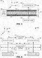
- FIG. 1 illustrates an example of a diagram of an atom beam gyroscope system 10 in accordance with an aspect of the invention.
- the atom beam gyroscope system 10 can be implemented in navigation or any of a variety of avionic applications, including aircraft and/or spacecraft.
- the atom beam gyroscope system 10 is configured to calculate a rotation angle ⁇ G of the atom beam gyroscope system 10 about a sensitive axis based on changes in measured optical energy absorption of alkali metal atoms in an atom beam resulting from a Doppler-shift in energy between absorbed photons and the alkali metal atoms due to an angular velocity of the alkali metal atoms.
- the atom beam gyroscope system 10 includes an atom beam system 12.
- the atom beam system 12 includes an atom beam source 14 that is configured to generate an atom beam comprising collimated alkali metal atoms.
- the alkali metal atoms can be Cesium (Cs) or Rubidium (Rb).
- the atom beam source 14 can be configured as a magneto-optical trap (MOT), such as a two-dimensional MOT or a three-dimensional MOT based on the configuration of collimating light (not shown), or can be configured as an evaporated alkali metal beam cell.
- MOT magneto-optical trap
- the atom beam system 12 also includes a detection region 16.
- the detection region 16 can be configured as an enclosed casing through which the atom beam is directed.
- the detection region 16 can be arranged to allow the atom beam to be directed orthogonal with respect to a sensitive axis of the atom beam gyroscope system 10. Therefore, the atom beam experiences an angular velocity with respect to the detection region 16 in response to a rotation of the atom beam gyroscope system 10 about the sensitive axis.
- the dimensions of the detection region 16 can thus be arranged to have sufficient length and width that are optimized based on a velocity and flux of the atom beam to allow the atom beam to be directed from the atom beam source 14 at a proximal end of the detection region 16 past a detection system 18 that is located at a distal end of the detection region 16.
- the detection system 18 includes at least one detection laser 20 and a respective at least one photodetector 22.
- the detection laser(s) 20 can be configured as any of a variety of types of lasers, such as distributed feedback laser(s) (DFBs) or vertical-cavity surface-emitting laser(s) (VCSELs).
- the detection laser(s) 20 are thus configured to illuminate the detection region 16 with an optical detection beam O DET , such that the optical detection beam O DET is arranged orthogonally with respect to both the atom beam and the sensitive axis, to pump the alkali metal atoms of the atom beam.
- the photodetector(s) 22 can be configured to measure an intensity of the optical detection beam exiting the detection region 16, demonstrated in the example of FIG. 1 as O DET ', to determine absorption of photons of the optical detection beam by the alkali metal atoms of the atom beam.
- the photodetector(s) 22 are configured to generate an intensity signal INT that corresponds to the intensity of the optical detection beam O DET ' exiting the detection region 16.
- the detection laser(s) 20 can be specifically tuned to generate the optical detection beam O DET at a specific wavelength that is optimized for detecting rotation of the atom beam gyroscope system 10 about the sensitive axis.
- the atom beam system 12 is demonstrated in the example of FIG. 1 as including a Doppler-free absorption spectrometer 24.
- the Doppler-free absorption spectrometer 24 can be configured as an arrangement of lasers and photodetectors that are implemented to tune the detection laser(s) 20 to a specific and stable wavelength.
- the Doppler-free absorption spectrometer 24 is demonstrated as providing a signal TUNE to the detection laser(s) 20.
- the detection laser(s) 20 can be configured as optically split from the lasers of the Doppler-free absorption spectrometer 24, such that the optical beams of the Doppler-free absorption spectrometer 24 and the optical detection beam O DET are generated from the same optical source.
- FIG. 2 illustrates an example useful for understating the invention, but that is not an embodiment thereof, of a Doppler-free absorption spectrometer system 50.
- the Doppler-free absorption spectrometer system 50 can correspond to the Doppler-free absorption spectrometer system 26 in the example of FIG. 1 . Therefore, reference is to be made to the example of FIG. 1 in the following description of the example of FIG. 2 .
- the Doppler-free absorption spectrometer system 50 includes an atom reservoir 52, which is demonstrated in the example of FIG. 2 as an enclosed region that includes an uncollimated mass of alkali metal atoms 54.
- the alkali metal atoms 54 can be one of Cesium (Cs) or Rubidium (Rb).
- the atom reservoir 52 can correspond to a portion of the atom beam source 14 in the example of FIG. 1 .
- the atom reservoir 52 can correspond to a portion of an MOT that is not illuminated by collimating light, or can correspond to a reservoir chamber of an evaporated alkali metal beam cell. Therefore, the alkali metal atoms 54 can be moving randomly in substantially all directions within the atom reservoir 52, and thus not yet directed as the atom beam of the atom beam gyroscope system 10.
- the Doppler-free absorption spectrometer system 50 also includes a Doppler-free absorption spectrometer 56.
- the Doppler-free absorption spectrometer 56 is demonstrated as including a first probe laser 58, a second probe laser 60, and a pump laser 62.
- the first probe laser 58 is configured to generate a first optical probe beam O PRB1
- the second probe laser 60 is configured to generate a second optical probe beam O PRB2
- the pump laser 62 is configured to generate an optical pump beam O PMP .
- a set of optics 64 is configured to direct the first optical probe beam O PRB1 , the second optical probe beam O PRB2 , and the optical pump beam O PMP through the atom reservoir 52.
- the Doppler-free absorption spectrometer system 50 also includes a first probe beam photodetector 66, a second probe beam photodetector 68, and a pump beam photodetector 70.
- the first probe beam photodetector 66 is configured to monitor an intensity of the first optical probe beam O PRB1
- the second probe beam photodetector 68 is configured to monitor an intensity of the second optical probe beam O PRB2
- the pump beam photodetector 70 is configured to monitor an intensity of the optical pump beam O PMP .
- the first optical probe beam O PRB1 is demonstrated as propagating substantially collinear with and in an opposite direction of the optical pump beam O PMP .
- the second optical probe beam O PRB2 is demonstrated as being substantially parallel with and in the opposite direction of the optical pump beam O PMP and being spaced apart from the optical pump beam O PMP within the atom reservoir 52.
- the first and second optical probe beams O PRB1 and O PRB2 can have an intensity magnitude that is less than or approximately equal to the intensity magnitude of the optical pump beam O PMP .
- the first and second optical probe beams O PRB1 and O PRB2 can have an intensity that is approximately 1 0% of the intensity of the optical pump beam O PMP .
- the first and second optical probe beams O PRB1 and O PRB2 exit the atom reservoir 52 as beams O PRB1 ' and O PRB2 ', respectively, and are provided to the first and second probe beam photodetectors 66 and 68.
- the optical pump beam O PMP exits the atom reservoir 52 as a beam O PMP ' and is provided to the pump beam photodetector 70.
- the Doppler-free absorption spectrometer 56 is thus configured to tune the detection laser(s) 20 in the example of FIG. 1 to a specific and stable wavelength.
- both the first and second optical probe beams O PRB1 ' and O PRB2 ' exiting the atom reservoir 52 can provide a Doppler-broadened absorption signal associated with the alkali metal atoms 54.
- the first optical probe beam O PRB1 ' also provides a non-linear saturated absorption spectroscopy signal within the Doppler-broadened absorption signal based on propagating substantially collinearly with and opposite the optical pump beam O PMP .
- the optical pump beam O PMP pumps a relatively large number of the alkali metal atoms 54 out of the atomic states that can absorb photons from the first optical probe beam O PRB1 based on the optical pump beam O PMP having a higher optical power relative to the first optical probe beam O PRB1 . Therefore, at the wavelength that the alkali metal atoms 54 would absorb photons of the first optical probe beam O PRB1 , there is a reduction in the absorption of the photons of the first optical probe beam O PRB1 relative to the absorption of the photons of the second optical probe beam O PRB2 .
- the Doppler-free absorption spectrometer 56 can detect a fundamental linewidth frequency of the alkali metal atoms 54 associated with a peak of an absorption spectrum of the alkali metal atoms 54 having a substantially zero axial velocity with respect to the optical probe beams O PRB1 and O PRB2 and the optical pump beam O PMP .
- all reference to an absorption spectrum of alkali metal atoms is with respect to an absorption spectrum of alkali metal atoms having substantially zero axial velocity with respect to pumping light, including the optical probe beams O PRB1 and O PRB2 and the optical pump beam O PMP , as well as the optical detection beam(s) O DET , respectively.
- the detection laser(s) 20 can be substantially locked to a wavelength that is determined by the Doppler-free absorption spectrometer 56.
- the first and second probe lasers 58 and 60, the pump laser 62, and the detection laser(s) 20 can all be associated with the same optical source.
- the detection laser(s) 20 can be substantially locked to the same substantially stable wavelength that the first and second probe lasers 58 and 60 and the pump laser 62 are locked based on the operation of the Doppler-free absorption spectrometer 56.
- the detection laser(s) 20 can be substantially locked to the absorption peak (i.e ., the fundamental linewidth frequency) itself, or can be locked to a frequency that is substantially offset from the absorption peak by a predetermined amount based on the operation of the Doppler-free absorption spectrometer 56.
- the wavelength of the first and second probe lasers 58 and 60, the pump laser 62, and the detection laser(s) 20 can all be substantially locked to a wavelength corresponding to a point on the absorption spectrum of the zero axial velocity alkali metal atoms 54 having a highest absolute value slope.
- the atom beam gyroscope system 10 also includes a magnetic field generator 26 that is configured to generate a magnetic field gradient B G at the detection region 16.
- the magnetic field gradient B G can have increasing magnetic field intensity off-axis with respect to the axis of the atom beam.
- the magnetic field gradient B G coupled with characteristics of the optical detection beam O DET , can be implemented to substantially adjust absorption parameters of the atom beam.
- the optical detection beam(s) O DET can be circularly-polarized, such as generated from the detection laser(s) 20 or based on the use of a polarizer (not shown). The orientation of the circular-polarization ( e .
- the magnetic field gradient B G and the circular-polarization of the optical detection beam(s) O DET can facilitate substantially greater or lesser absorption of photons of the optical detection beam(s) O DET by the alkali metal atoms of the atom beam depending on an off-axis location of the alkali metal atoms from the nominal path of the atom beam due to the Zeeman effect.
- the magnitude of the intensity signal TNT can indicate a relative absorption of the photons of the optical detection beam(s) O DET by the alkali metal atoms in the atom beam that corresponds to an axial velocity, and thus an axial location, of the alkali metal atoms relative to the optical detection beam(s) O DET based on the Zeeman-shift and a Doppler-shift of the alkali metal atoms relative to the photons of the optical detection beam(s) O DET .
- the Zeeman- and Doppler-shifts of the alkali metal atoms coupled with the optical detection beam(s) O DET having a wavelength tuned to a location on the optical absorption spectrum for substantially zero axial velocity alkali metal atoms, as described above, ensures that very slight deviations of the alkali metal atoms from the nominal beam path of the atom beam result in significant changes in the magnitude of the intensity signal INT.
- the atom beam gyroscope system 10 further includes a gyroscope sensor 28.
- the gyroscope sensor 28 includes a gyroscope processor 30 that is configured to determine an angular velocity of the rotation of the atom beam gyroscope system 10 about the sensitive axis, and thus a rotation angle ⁇ G of the atom beam gyroscope system 10, based on the magnitude of the intensity signal INT.
- the gyroscope processor 30 can be programmed to identify a correlation between the magnitude of the intensity signal INT and an axial location of the alkali metal atoms of the atom beam relative to the optical detection beam(s) O DET , and thus the nominal beam path of the atom beam.
- the gyroscope processor 30 can determine the angular velocity of the alkali metal atoms in the beam path based on the changes in the intensity signal INT corresponding to relative axial locations of the alkali metal atoms from the nominal beam path of the atom beam. Accordingly, the gyroscope processor 30 can translate the determined angular velocity of the alkali metal atoms in the atom beam to the rotation angle ⁇ G of the atom beam gyroscope system 10 about the sensitive axis.
- FIG. 3 illustrates another example of an atom beam gyroscope system 100 in accordance with an aspect of the invention.
- the atom beam gyroscope system 100 can correspond to a portion of the atom beam gyroscope 10 in the example of FIG. 1 ( e.g ., the atom beam system 12 and the detection system 18). Therefore, reference is to be made to the atom beam gyroscope system 10 in the example of FIG. 1 in the following description of the example of FIG. 3 .
- the atom beam gyroscope system 100 includes an atom beam source 102 and a detection region 104.
- the atom beam source 102 can be configured as a two- or three-dimensional MOT or an evaporated alkali metal beam cell.
- the atom beam source 102 thus generates an atom beam 106 in a beam path in the detection region 104 along a +Z-axis direction, as indicated by the Cartesian coordinate system indicated at 108.
- the atom beam 106 is directed along the Z-axis with substantially no component of velocity in the +/- Y-axis direction.
- the atom beam gyroscope system 100 and thus the atom beam system 10 in the example of FIG. 1 , can be tuned to substantially account for the effect of external forces, such as gravity, on the atom beam 106.
- the sensitive axis can intersect a location of the atom beam gyroscope system 100 at a location that is approximately at or near the atom beam source 102 to affect the angular velocity of the alkali metal atoms in the atom beam 106 substantially equally in response to rotation about the sensitive axis in either direction.
- the atom beam gyroscope system 100 also includes a detection laser 110 and a photodetector 112.
- the detection laser 110 is configured to generate the optical detection beam O DET that is directed substantially in the +Y direction, and thus orthogonal to both a nominal beam path of the atom beam 106, indicated at 114, and the sensitive axis of the atom beam gyroscope system 100.
- the optical detection beam O DET can be circularly-polarized and can be tuned to a wavelength that is offset from the peak of the optical absorption spectrum of the alkali metal atoms of the atom beam 106, such as at a greatest absolute-value slope of the peak.
- the photodetector 112 is configured to measure an intensity of the optical detection beam O DET ' exiting the detection region 104.
- the photodetector 112 can thus generate the intensity signal INT that has a magnitude based on the intensity of the optical detection beam O DET ' exiting the detection region 104. Accordingly, the magnitude of the intensity signal INT corresponds to an amount of absorption of the photons of the optical detection beam O DET by the alkali metal atoms of the atom beam 106.
- the measurement of the intensity of the optical detection beam O DET ' exiting the detection region 104 via the photodetector 112 is but one example of measuring the absorption of photons of the optical detection beam O DET by the alkali metal atoms of the atom beam 106.
- the atom beam gyroscope system 10 in the example of FIG. 1 and thus the atom beam gyroscope system 100 in the example of FIG. 3 , can implement fluorescence detection that measures light emission from the alkali metal atoms of the atom beam 106.
- the atom beam gyroscope system 100 can instead be configured to include at least the photodetector 112 out of the path of the optical detection beam O DET , such that the photodetector 112 is configured to measure photons emitted from the alkali metal atoms after having been pumped by the optical detection beam O DET . Because the photons emitted from the alkali metal atoms is substantially equal to the photons absorbed by the alkali metal, the photodetector 112 in a fluorescence detection arrangement of the atom beam gyroscope system 100 can similarly be configured to measure the absorption of photons of the optical detection beam O DET by the alkali metal atoms of the atom beam 106.
- a magnetic field gradient B G is applied to the detection region 104.
- the magnetic field gradient B G can be generated by the magnetic field generator 26 in the example of FIG. 1 .
- the magnetic field gradient B G is demonstrated as having an intensity of approximately zero along the nominal beam path 114 of the atom beam 106, with increasing intensity in the +/-Y-axis directions off-axis of the nominal beam path 114. It is to be understood that the magnetic field gradient B G could also increase in the +/- X-axis directions, as well.
- the alkali metal atoms of the atom beam 106 deviate off-axis from the nominal beam path 114 of the atom beam 106, the alkali metal atoms experience a change in potential energy due to an interaction between local magnetic fields resulting from electron spin and the intensity of the magnetic field gradient B G based on the Zeeman effect. Accordingly, the change in potential energy of the alkali metal atoms that deviate off-axis from the nominal beam path 114 can result in a change in the absorption of photons of the optical detection beam O DET by the alkali metal atoms based on the axial location of the alkali metal atoms relative to the nominal beam path 114.
- the optical detection beam O DET can be circularly-polarized with an orientation (e.g ., right- or left-handed) to substantially increase the probability of absorption of photons for alkali metal atoms in the -Y axis relative to the nominal beam path 114 and substantially decrease the probability of absorption of photons for alkali metal atoms in the +Y axis relative to the nominal beam path 114, as indicated by the magnitude of the intensity signal INT.
- the magnetic field gradient B G can be either a positive or negative gradient, as appropriate for the direction of circular polarization of the optical detection beam O DET .
- the optical detection laser 110 can be tuned to generate the optical detection beam O DET at a wavelength that corresponds to a greatest absolute value slope of the absorption spectrum of the alkali metal atoms along the nominal beam path 114.
- the optical detection beam O DET can have a wavelength that substantially increases the probability of absorption of photons by alkali metal atoms in the - Y axis relative to the nominal beam path 114 and substantially decrease the probability of absorption of photons for alkali metal atoms in the +Y axis relative to the nominal beam path 114 based on a Doppler-shift of the energy of the alkali metal atoms relative to the optical detection beam O DET , as indicated by the magnitude of the intensity signal INT.
- the gyroscope processor 30 in the example of FIG. 1 can accurately calculate the rotation angle ⁇ G of the atom beam gyroscope system 100 about the sensitive axis.
- the atom beam system 12 and the detection system 18 can be configured substantially similar to the atom beam system 100 in the example of FIG. 3 , such that the atom beam source 14 generates a single atom beam.
- the atom beam gyroscope system 10 can be configured to calculate the rotation angle ⁇ G about the sensitive axis based on the motion of the alkali metal atoms relative to the nominal beam path of the atom beam.
- such motion of the alkali metal atoms relative to the nominal beam path of the atom beam can also result from a linear acceleration of the atom beam gyroscope system 10.
- the gyroscope processor 30 may not be able to differentiate between rotation and linear acceleration of the atom beam gyroscope system 10 based solely on axial velocity of the alkali metal atoms relative to the optical detection beam(s) O DET .
- the gyroscope sensor 28 includes an accelerometer 32 configured to detect and/or calculate a linear acceleration of the atom beam gyroscope system 10.
- the accelerometer 32 can provide the linear acceleration information to the gyroscope processor 30, such that the gyroscope processor 30 can substantially cancel the linear acceleration of the atom beam gyroscope system 10 from the calculation the rotation angle ⁇ G of the atom beam gyroscope system 10 about the sensitive axis.
- the gyroscope processor 30 can calculate the rotation angle ⁇ G of the atom beam gyroscope system 10 about the sensitive axis based on the magnitude of the intensity signal INT and the linear acceleration of the atom beam gyroscope 10, as measured by the accelerometer 32.
- the respective atom beam gyroscope systems 10 and 100 can still be subject to the effects of linear acceleration parallel to the propagation direction of atom beam 106 (i.e ., the Z-axis).
- linear acceleration parallel to the direction of the atom beam 106 can change the velocity of the atom beam 106 relative to the gyroscope sensor 28, and thus the linear velocity and displacement of the atoms of the atom beam 106 for a given rotational rate about the sensitive axis.
- a gyroscope scale factor sensitivity to acceleration rate along the direction of the atom beam 106 can occur.
- the accelerometer 32 can include an accelerometer configured to measure acceleration in the direction of the atom beam 106, such as in +/- Z axis. Accordingly, the measured acceleration in the +/- Z axis can be factored-out from the calculation of the rotation of the atom beam gyroscope system 100 about the sensitive axis.
- the gyroscope scale factor sensitivity can be substantially mitigated by controlling a velocity of the atom beam 106, such as at the atom beam source 14.
- a velocity of the atom beam 106 such as at the atom beam source 14.
- two counter-propagating properly tuned circularly-polarized optical beams can be directed parallel to the propagation direction of the atom beam 106.
- the tuning of these two optical beams can be such that the desired atom beam velocity results in a minimum absorption of these optical beams.
- any atoms moving faster or slower than this velocity can experience a pushing force that substantially alters their velocity until they match the velocity corresponding to a minimum absorption of these two optical beams. This occurs due to a Doppler-shift effect analogous to the effect used for measurement of the rotation rate of the atom beam gyroscope system 10.
- atoms of the atom beam 106 that are slower or faster than the control velocity can be Doppler-shifted relative to the two velocity control optical beams so as to increase or decrease the probability of absorbing a photon from the detection beam.
- Proper tuning of the two beams of light can ensure that these changes in absorption probability can result in a net force altering the velocities of the atoms such that they more closely match the control velocity.
- the control velocity can thus essentially eliminate the atom beam velocity sensitivity to linear accelerations parallel to the propagation direction of the atom beam 106.
- FIG. 4 illustrates yet another example of an atom beam gyroscope system 150 in accordance with an aspect of the invention.
- the atom beam gyroscope system 150 includes a bi-directional atom beam source 152, a first detection region 154, and a second detection region 156.
- the bi-directional atom beam source 152 can be configured as a two-dimensional MOT or can be configured as two separate three-dimensional MOTs or evaporated alkali metal beam cells.
- the bi-directional atom beam source 152 generates a first atom beam 158 in a beam path in the first detection region 154 along a -Z-axis direction and a second atom beam 160 in a beam path in the second detection region 156 along a +Z-axis direction, as indicated by the Cartesian coordinate system indicated at 162.
- the first and second atom beams 158 and 160 are thus directed in opposite directions with respect to each other. Accordingly, at substantially no rotation of the atom beam gyroscope system 150 about the X-axis ( i.e . , the sensitive axis in the example of FIG. 4 ), the first and second atom beams 158 and 160 are directed along the -Z and +Z-axes, respectively, with substantially no component of velocity in the +/- Y-axis direction.
- the atom beam gyroscope system 150 also includes a first detection laser 164, a second detection laser 166, a first photodetector 168, and a second photodetector 170.
- the first detection laser 164 is configured to generate a first optical detection beam O DET1 in the first detection region 154 and the second detection laser 166 is configured to generate a second optical detection beam O DET2 in the second detection region 154.
- Each of the first and second detection beams O DET1 and O DET2 are directed substantially in the +Y direction, and thus orthogonal to the nominal beam paths of the first and second atom beams 158 and 160 and the sensitive axis of the atom beam gyroscope system 150.
- first and second detection beams O DET1 and O DET2 need not be directed in the same direction, but could be directed in opposite directions. Similar to as described above regarding the example of FIG. 3 , a magnetic field gradient B G can be applied to the first and second detection regions 154 and 156 and the first and second optical detection beams O DET1 and O DET1 can each be circularly-polarized. Furthermore, the first and second optical detection beams O DET1 and O DET2 can be tuned to a wavelength that is offset from the peak of the optical absorption spectrum of the alkali metal atoms of the atom beams 158 and 160, such as at a greatest absolute-value slope of the peak.
- the first and second photodetectors 168 and 170 are each configured to measure an intensity of the respective first and second optical detection beams O DET1 ' and O DET2 ' exiting the respective detection regions 154 and 156.
- the first photodetector 168 can thus generate an intensity signal INT_1 that has a magnitude based on the intensity of the first optical detection beam O DET1 ' exiting the first detection region 154
- the second photodetector 170 can thus generate an intensity signal INT_2 that has a magnitude based on the intensity of the second optical detection beam O DET2 ' exiting the second detection region 156.
- the magnitude of the intensity signals INT_1 and INT_2 correspond to an amount of absorption of the photons of the first and second optical detection beams O DET1 and O DET2 by the alkali metal atoms of the respective atom beams 158 and 160.
- the first and second intensity signals INT_1 and INT_2 are each provided to a gyroscope sensor 172.
- each of the first and second intensity signals INT_1 and INT_2 can be associated with the motion of the alkali metal atoms in the respective first and second atom beams 158 and 160 separately and independently with respect to each other.
- the gyroscope sensor 172 can be configured to determine both rotation of the atom beam gyroscope system 150 about the sensitive axis and linear acceleration of the atom beam gyroscope system 150 based on a difference between the magnitudes of the first and second intensity signals INT_1 and INT_2.
- rotation about the sensitive axis in a clockwise direction can result in an axial velocity of the alkali metal atoms in the first atom beam 158 in the -Y direction and an axial velocity of the alkali metal atoms in the second atom beam 160 in the +Y direction.
- Rotation about the sensitive axis in a counter-clockwise direction can result in an axial velocity of the alkali metal atoms in the first atom beam 158 in the +Y direction and an axial velocity of the alkali metal atoms in the second atom beam 160 in the -Y direction.
- a linear acceleration of the atom beam gyroscope system 150 in the +Y direction can result in an axial velocity of the alkali metal atoms in both the first and second atom beams 158 and 160 in the -Y direction, and in the +Y direction as a result of a linear acceleration in the -Y direction.
- the gyroscope processor 30 in the example of FIG. 1 can be configured to determine both linear acceleration and rotation about the sensitive axis based on the relative magnitudes of the first and second intensity signals INT_1 and INT_2. Specifically, the gyroscope processor 30 can be configured to factor out the linear acceleration in the Y-axis from the calculation of the rotation angle ⁇ G of the atom beam gyroscope system 150 about the sensitive axis. Accordingly, an accelerometer can be omitted from the gyroscope sensor 172 in the example of FIG. 4 with respect to measuring linear acceleration in the Y-axis.
- a linear acceleration in the Z-axis can result in an increase in velocity in one of the atom beams 158 and 160 and a substantially equal decrease in velocity in the other of the atom beams 158 and 160, such that the atom beam gyroscope system 150 can be subject to gyroscope scale factor sensitivity. Therefore, similar to as described above regarding the example of FIG. 3 , the atom beam gyroscope system 150 can include an accelerometer or can implement velocity control of the atom beams 158 and 160 to substantially the mitigate gyroscope scale factor sensitivity resulting from linear acceleration in the Z-axis.
- the atom beam gyroscope systems 100 and 150 in the examples of FIGS. 3 and 4 include a single optical detection beam and photodetector pair for each detection region
- the atom beam gyroscope systems 100 and 150 can also include additional optical detection beam and photodetector pairs, such as for redundancy or for calculation of rotation angle about a different sensitive axis.
- each of the respective detection regions could also include an optical detection beam and photodetector pair arrange to pump the alkali metal atoms in the +/-X direction, such as to also calculate rotation of the respective atom beam gyroscope systems 100 and 150 about the Y-axis.
- FIG. 5 illustrates yet a further example of an atom beam gyroscope system 200 in accordance with an aspect of the invention.
- the atom beam gyroscope system 200 includes a bi-directional atom beam source 202, a first detection region 204, and a second detection region 206.
- the bi-directional atom beam source 202 can be configured as a two-dimensional MOT or can be configured as two separate three-dimensional MOTs or evaporated alkali metal beam cells.
- the bi-directional atom beam source 202 generates a first atom beam 208 in a beam path in the first detection region 204 along a -Z-axis direction and a second atom beam 210 in a beam path in the second detection region 206 along a +Z-axis direction, similar to as described above in the example of FIG. 4 with reference to the Cartesian coordinate system demonstrated at 162.
- the first and second atom beams 208 and 210 are thus directed in opposite directions with respect to each other, similar to as described above with respect to the example of FIG. 4 .
- the atom beam gyroscope system 200 also includes a first detection laser 214, a second detection laser 216, a first photodetector 218, and a second photodetector 220. Similar to as described above in the example of FIG. 4 , the first detection laser 214 is configured to generate a first optical detection beam O DET1 in the first detection region 204 and the second detection laser 216 is configured to generate a second optical detection beam O DET2 in the second detection region 204. Thus, the intensity of the respective first and second optical detection beams O DET1 ' and O DET2 ' exiting the respective detection regions 204 and 206 can be measured via the first and second photodetectors 218 and 220.
- the first photodetector 218 can thus generate an intensity signal INT_1 that has a magnitude based on the intensity of the first optical detection beam O DET1 ' exiting the first detection region 204
- the second photodetector 170 can thus generate an intensity signal INT_2 that has a magnitude based on the intensity of the second optical detection beam O DET2 ' exiting the second detection region 206.
- the magnitude of the intensity signals INT_1 and INT_2 correspond to an amount of absorption of the photons of the first and second optical detection beams O DET1 and O DET2 by the alkali metal atoms of the respective atom beams 208 and 210.
- the optical detection beams O DET1 and O DET2 can be tuned to a wavelength corresponding to a point on the absorption spectrum at a highest absolute-value slope.
- the absorption of the photons of the optical detection beams O DET1 and O DET2 by the atom beams 208 and 210 can have a limited dynamic range based on a lack of linearity along the absorption spectrum as the alkali atoms increase in +/- axial velocity relative to the optical detection beams O DET1 and O DET2 .
- the atom beam gyroscope system 200 includes a first error generator 222 and a second error generator 224 configured to monitor a magnitude of the intensity signals INT_1 and INT_2 relative to a reference signal INT_REF,
- the reference signal INT_REF can have a magnitude that corresponds to an absorption intensity of the point on the absorption spectrum at a highest absolute-value slope.
- the first and second error generators 222 and 224 can generate respective error signals ERR_1 and ERR_2 corresponding to a difference between the intensity signals INT_1 and INT_2 relative to the reference signal INT_REF, such as resulting from the increase in +/- axial velocity relative to the optical detection beams O DET1 and O DET2 .
- the error signals ERR_1 and ERR_2 can thus have magnitudes that vary linearly with the frequency offset along the absorption spectrum resulting from the change in intensity of the INT_1 and INT_2 relative to the reference signal INT_REF.
- the error signals ERR_1 and ERR_2 are provided to each of the respective first and second detection lasers 214 and 216 to dynamically tune the first and second detection lasers 214 and 216. Specifically, because the error signals ERR_1 and ERR_2 have magnitudes that vary linearly with the frequency offset along the absorption spectrum, the error signals ERR_1 and ERR_2 can tune the respective first and second detection lasers 214 and 216 to a frequency corresponding to the point on the absorption spectrum at the highest absolute-value slope.
- the absorption of the photons of the optical detection beams O DET1 and O DET2 by the atom beams 208 and 210 can have a substantially maximum dynamic range based on the frequency of the optical detection beams O DET1 and O DET2 being substantially fixed to the point on the absorption spectrum at the highest absolute-value slope, even during rotation of the atom beam gyroscope system 200 about the sensitive axis.
- the tuning of the first and second detection lasers 214 and 216 could be based on the error signals ERR_1 and ERR_2 being provided to respective frequency shifting devices, such as acousto-optic modulators, in the examples of the detection lasers 214 and 216 having substantially fixed frequencies.
- the error signals ERR_1 and ERR_2 are also provided to a gyroscope sensor 226, which can correspond to the gyroscope sensor 30 in the example of FIG. 1 .
- the gyroscope sensor 226 can measure the rotation of the atom beam gyroscope system 200 about the sensitive axis based on the magnitudes of the error signals ERR_1 and ERR_2.
- the magnitudes of the error signals ERR_1 and ERR_2 vary linearly with the frequency offset along the absorption spectrum resulting from the change in intensity of the INT_1 and INT_2 relative to the reference signal INT_REF.
- the measurement of the rotation of the atom beam gyroscope system 200 about the sensitive axis can be performed with a substantially maximized sensitivity and linearity. Accordingly, the atom beam gyroscope system 200 can measure the rotation about the sensitive axis with a high degree of accuracy. It is to be understood that the inclusion of the first and second error generators 222 and 224 to calculate the rotation about the sensitive axis is not limited to use in a two atom beam system, such as the atom beam gyroscope system 200, but could instead also be included in a single atom beam gyroscope system, such as the atom beam gyroscope system 100 in the example of FIG. 3 .
- FIG. 6 illustrates an example of a three-axis gyroscope system 250 in accordance with an aspect of the invention.
- the three-axis gyroscope system 250 can be implemented in any of a variety of navigation control systems, such as for aircraft and/or spacecraft, or device to monitor yaw, pitch, and roll rotational motion information.
- the three-axis gyroscope system 250 includes an X-axis gyroscope system 252, a Y-axis gyroscope system 254, and a Z-axis gyroscope system 256.
- each of the X-axis, Y-axis, and Z-axis gyroscope systems 252, 254, and 256 can be configured substantially similar to the atom beam gyroscope system 10 in the example of FIG. 1 .
- FIG. 1 In the example of FIG.
- the X-axis gyroscope system 252 can have a sensitive axis about the X-axis
- the Y-axis gyroscope system 254 can have a sensitive axis about the Y-axis
- the Z-axis gyroscope system 256 can have a sensitive axis about the Z-axis.
- the axes of rotation of the respective atom beam gyroscope systems 252, 254, and 256 are indicated in the example of FIG. 6 by a Cartesian coordinate system 258.
- each of the X-axis, Y-axis, and Z-axis gyroscope systems 252, 254, and 256 can be configured to calculate a rotation angle about the respective sensitive axes based on changes in measured optical energy absorption of alkali metal atoms in an atom beam resulting from a Doppler-shift in energy between absorbed photons and the alkali metal atoms due to an angular velocity of the alkali metal atoms.
- the three-axis gyroscope system 250 can measure rotational motion about all three of the sensitive axes demonstrated by the X-axis, Y-axis, and Z-axis gyroscope systems 252, 254, and 256.
- each of the X-axis, Y-axis, and Z-axis gyroscope systems 252, 254, and 256 are demonstrated as outputting signals that include the respective rotation angles ⁇ G_X , ⁇ G_Y , and ⁇ G_Z to a motion sensor 260.
- the motion sensor 260 can thus be configured to determine an aggregate three-axis rotational motion of the associated vehicle or device that includes the three-axis gyroscope system 250. Therefore, the yaw, pitch, and roll of the associated vehicle or device that includes the three-axis gyroscope system 250 can be determined. Accordingly, the motion sensor 260 can be configured to display, output, and/or report the three-axis rotational motion of the associated vehicle or device that includes the three-axis gyroscope system 250.
- FIG. 7 a methodology in accordance with various aspects of the present invention will be better appreciated with reference to FIG. 7 . While, for purposes of simplicity of explanation, the methodologies of FIG. 7 are shown and described as executing serially, it is to be understood and appreciated that the present invention is not limited by the illustrated order, as some aspects could, in accordance with the present invention, occur in different orders and/or concurrently with other aspects from that shown and described herein. Moreover, not all illustrated features may be required to implement a methodology in accordance with an aspect of the present invention.
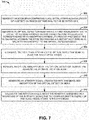
- FIG. 7 illustrates an example of a method 300 for calculating a rotation angle about a sensitive axis.
- an atom beam comprising alkali metal atoms is generated along a length of a detection region orthogonal to the sensitive axis.
- the alkali metal atoms can be Rubidium (Rb) or Cesium (Cs).
- the atom beam can be generated by a variety of different kinds of atom beam sources, such as a two- or three-dimensional magneto-optical trap (MOT) or an evaporated alkali metal beam cell.
- MOT magneto-optical trap
- an optical detection beam is generated having a first wavelength that is offset by a predetermined amount from a second wavelength corresponding to an absorption probability peak of photons by the alkali metal atoms in the atom beam having a substantially zero axial velocity with respect to the optical detection beam.
- the optical detection beam can be generated from a detection laser that is locked to the wavelength based on a Doppler-free absorption spectrometer.
- the detection laser can be optically split from the Doppler-free absorption spectrometer.
- the detection region is illuminated via the optical detection beam to pump the alkali metal atoms.
- the optical detection beam can pass through the detection region in a direction that is orthogonal to both the sensitive axis and a nominal beam path of the atom beam.
- an optical absorption of the optical detection beam by the alkali metal atoms in the atom beam is measured. The optical absorption can be measured based on measuring an intensity of the optical detection beam exiting the detection region or by measuring fluorescence of photons being emitted from the alkali metal atoms.
- the absorption can be based not only on a Doppler-shift of the photons of the optical detection beam relative to the alkali metal atoms deviating from the nominal atom beam path, but also based on a Zeeman-shift resulting from a magnetic field gradient and circular-polarization of the optical detection beam.
- an intensity signal associated with the measured absorption of the optical detection beam is generated.
- the intensity signal can have a magnitude associated with an intensity of the optical detection beam exiting the detection region, thus indicating absorption of the photons of the optical detection beam by the alkali metal atoms of the atom beam.
- the intensity signal can be one of two intensity signals from two separate optical detection beams for two atom beams directed in opposite directions. Thus, the two intensity signals can be implemented to determined and factor out linear acceleration of the atom beam gyroscope system.
- the rotation angle about the sensitive axis is calculated based on a magnitude of the intensity signal due to a Doppler-shift in energy of the alkali metal atoms in the atom beam.
- the Doppler-shift can result from an axial velocity of the alkali metal atoms relative to the optical detection beam resulting from rotation of the gyroscope system about the sensitive axis.
Landscapes
- Physics & Mathematics (AREA)
- General Physics & Mathematics (AREA)
- Engineering & Computer Science (AREA)
- Radar, Positioning & Navigation (AREA)
- Remote Sensing (AREA)
- Condensed Matter Physics & Semiconductors (AREA)
- Lasers (AREA)
- Investigating Or Analysing Materials By Optical Means (AREA)
- Gyroscopes (AREA)
Claims (13)
- Atomstrahlkreiselsystem (10), umfassend:ein Atomstrahlsystem (12), das konfiguriert ist, um einen ersten Atomstrahl (158) entlang einer Länge eines ersten Erfassungsbereichs (154) und einen zweiten Atomstrahl (160) entlang einer Länge eines zweiten Erfassungsbereichs (156) zu erzeugen, wobei der erste und zweite Atomstrahl (158, 160) Alkalimetallatome umfassen, die sich orthogonal zu einer empfindlichen Achse und in entgegengesetzten Richtungen relativ zueinander ausbreiten;ein Erfassungssystem (18), das einen ersten Erfassungslaser (164), einen zweiten Erfassungslaser (166), einen ersten Fotodetektor (168) und einen zweiten Fotodetektor (170) umfasst, wobei der erste Erfassungslaser (164) konfiguriert ist, um einen ersten optischen Erfassungsstrahl (ODET) zu erzeugen, der orthogonal zu dem ersten Atomstrahl, dem zweiten Atomstrahl, und zu der empfindlichen Achse ist und der den ersten Erfassungsbereich (154) beleuchtet, um die Alkalimetallatome zu pumpen, wobei der zweite Erfassungslaser (166) konfiguriert ist, um einen zweiten optischen Erfassungsstrahl (ODET') zu erzeugen, der orthogonal zu dem ersten Atomstrahl, dem zweiten Atomstrahl und zu der empfindlichen Achse ist und der den zweiten Erfassungsbereich (156) beleuchtet, um die Alkalimetallatome zu pumpen, wobei der erste Fotodetektor (168) konfiguriert ist, um eine Intensität des ersten optischen Erfassungsstrahls (ODET) zu messen, der aus dem ersten Erfassungsbereich (154) austritt, und um ein erstes Intensitätssignal (INT_1) zu erzeugen, das der gemessenen Intensität zugehörig ist, und der zweite Fotodetektor (170) konfiguriert ist, um eine Intensität des zweiten optischen Erfassungsstrahls (ODET') zu messen, der aus dem zweiten Erfassungsbereich (156) austritt, und um ein zweites Intensitätssignal (INT_2) zu erzeugen, das der gemessenen Intensität zugehörig ist; undeinen Kreiselsensor (28), der dafür konfiguriert ist, um die Drehung und Linearbeschleunigung des Atomstrahlkreiselsystems (10) um die empfindliche Achse herum basierend auf einer Größe des ersten und zweiten Intensitätssignals (INT_1, INT_2) aufgrund einer Doppler-Verschiebung der Energie der Alkalimetallatome in dem ersten und zweiten Atomstrahl (158, 160) zu berechnen.
- System nach Anspruch 1, ferner umfassend einem Magnetfeldgenerator (26), der konfiguriert ist, um einen Magnetfeldgradienten zu erzeugen, der von einer Nennachse des ersten und zweiten Atomstrahls (158, 160) aus ansteigt, und wobei der erste und zweite optische Erfassungsstrahl (ODET, ODET') zirkular polarisiert sind, um eine Wahrscheinlichkeit einer Absorption von Photonen des ersten und zweiten optischen Erfassungsstrahls (ODET, ODET') durch die Alkalimetallatome in dem ersten und dem zweiten Atomstrahl (158, 160) mit einer von Null verschiedenen axialen Geschwindigkeit in Bezug auf den ersten und zweiten optischen Erfassungsstrahl (ODET, ODET') im Wesentlichen einzustellen.
- System nach Anspruch 1, wobei das Erfassungssystem (18) einen Beschleunigungsmesser (32) umfasst, der konfiguriert ist, um die Linearbeschleunigung des Atomstrahlkreiselsystems (10) aus der Erfassung der Drehung des Atomstrahlkreiselsystems (10) um die empfindliche Achse herum zu erfassen und auszuklammern.
- System (10) nach Anspruch 1, ferner umfassend eine Atomstrahlquelle (14), die ein Doppler-freies Absorptionsspektrometer (24) umfasst, das konfiguriert ist, um eine Wellenlänge des Erfassungslasers (20) im Wesentlichen zu stabilisieren, wobei das Doppler-freie Absorptionsspektrometer (24) umfasst:einen ersten Sondenlaser (58), der konfiguriert ist, um einen ersten optischen Sondenstrahl (OPRB1) durch die Alkalimetallatome zu erzeugen;einen Pumplaser (62), der konfiguriert ist, um einen optischen Pumpstrahl (OPMP) zu erzeugen, der im Wesentlichen kollinear mit dem ersten optischen Sondenstrahl (OPRB1) ist und sich in einer entgegengesetzten Richtung zu diesem ausbreitet;einen zweiten Sondenlaser (60), der konfiguriert ist, um einen zweiten optischen Sondenstrahl (OPRB2) durch die Alkalimetallatome zu erzeugen, wobei der zweite optische Sondenstrahl (OPRB2) von dem ersten optischen Sondenstrahl (OPRB1) beabstandet und im Wesentlichen parallel zu diesem ist, wobei sich der erste und zweite optische Sondenstrahl (OPRB1 und OPRB2) in der gleichen Richtung ausbreiten; undmehrere Fotodetektoren (66 und 68), die konfiguriert sind, um eine Intensität des ersten und zweiten optischen Sondenstrahls (OPRB1 und OPRB2) und des optischen Pumpstrahls zu messen, wobei die Wellenlänge des Erfassungslasers (20) im Wesentlichen stabilisiert ist, basierend auf einem Unterschied in der gemessenen Intensität des ersten und zweiten optischen Sondenstrahls (OPRB1 und OPRB2).
- System (10) nach Anspruch 4, wobei die Atomstrahlquelle (14) als eine aus einer verdampften Alkalimetallstrahlzelle, einer zweidimensionalen magneto-optischen Falle und einer dreidimensionalen magneto-optischen Falle konfiguriert ist.
- System (10) nach Anspruch 1, wobei der erste und zweite Erfassungslaser (164, 166) abgestimmt sind, um den ersten und den zweiten optischen Erfassungsstrahl (ODET, ODET') bei einer ersten Wellenlänge zu erzeugen, die um eine vorgegebene Menge von einer zweiten Wellenlänge versetzt ist, die einer Absorptionswahrscheinlichkeitsspitze von Photonen durch die Alkalimetallatome in dem ersten und zweiten Atomstrahl (158, 160) entspricht, die eine Axialgeschwindigkeit von im Wesentlichen Null in Bezug auf den ersten und zweiten optischen Erfassungsstrahl (ODET, ODET') haben.
- System (10) nach Anspruch 6, wobei die vorgegebene Menge einem Anteil der Absorptionswahrscheinlichkeitsspitze mit der größten absoluten Wertneigung entspricht.
- System (10) nach Anspruch 6, ferner umfassend einen Fehlersignalgenerator, der konfiguriert ist, um ein Fehlersignal mit einer Größe zu erzeugen, die auf einer Differenz zwischen einer Größe des ersten und zweiten Intensitätssignals (INT_1, INT_2) und einem Referenzsignal basiert, wobei das Fehlersignal implementiert wird, um den ersten und zweiten Erfassungslaser (164, 166) dynamisch abzustimmen, um den ersten und zweiten optischen Erfassungsstrahl (ODET, ODET') auf einer Absorption zu halten, die der vorgegebenen Menge der Absorptionswahrscheinlichkeitsspitze entspricht, und wobei der Kreiselsensor (28) konfiguriert ist, um die Drehung des Atomstrahlkreiselsystems (10) um die empfindliche Achse herum basierend auf der Größe des Fehlersignals zu berechnen.
- Verfahren zum Berechnen eines Drehwinkels um eine empfindliche Achse herum, umfassend:Erzeugen eines ersten Atomstrahls (158) entlang einer Länge eines ersten Erfassungsbereichs (154);Erzeugen eines zweiten Atomstrahls (160) entlang einer Länge eines zweiten Erfassungsbereichs (156), wobei der erste und zweite Atomstrahl (158, 160) Alkalimetallatome umfassen, die sich orthogonal zu der empfindlichen Achse und in entgegengesetzten Richtungen relativ zueinander ausbreiten;Erzeugen, mit einem ersten Erfassungslaser (164), eines ersten optischen Erfassungsstrahls (ODET), der orthogonal zu dem ersten Atomstrahl, dem zweiten Atomstrahl und zu der empfindlichen Achse ist und der den ersten Erfassungsbereich (154) beleuchtet, um die Alkalimetallatome zu pumpen;Erzeugen, mit einem zweiten Erfassungslaser (166), eines zweiten optischen Erfassungsstrahls (ODET'), der orthogonal zu dem ersten Atomstrahl, dem zweiten Atomstrahl und zu der empfindlichen Achse ist und der den zweiten Erfassungsbereich (156) beleuchtet, um die Alkalimetallatome zu pumpen;Messen, mit einem ersten Fotodetektor (168), einer Intensität des ersten optischen Erfassungsstrahls (ODET), der aus dem ersten Erfassungsbereich (154) austritt;Erzeugen, mit dem ersten Photodetektor (168), eines ersten Intensitätssignals (INT_1), das der gemessenen Intensität des ersten optischen Erfassungsstrahls (ODET) zugehörig ist, der aus dem ersten Erfassungsbereich (154) austritt;Messen, mit einem zweiten Fotodetektor (170), einer Intensität des zweiten optischen Erfassungsstrahls (ODET'), der aus dem zweiten Erfassungsbereich (156) austritt;Erzeugen, mit dem zweiten Fotodetektor (170), eines zweiten Intensitätssignals (INT_2), das der gemessenen Intensität des zweiten optischen Erfassungsstrahls (ODET') zugehörig ist, der aus dem zweiten Erfassungsbereich (156) austritt; undBerechnen der Drehung um die empfindliche Achse herum basierend auf einer Größe des ersten und zweiten Intensitätssignals (INT_1, INT_2) aufgrund einer Doppler-Verschiebung der Energie der Alkalimetallatome in dem ersten und zweiten Atomstrahl (158, 160).
- Verfahren nach Anspruch 9, ferner umfassend das Erzeugen eines Magnetfeldgradienten mit einem Magnetfeldgenerator (26), der von einer Nennachse des ersten und zweiten Atomstrahls (158, 160) aus ansteigt, und wobei der erste und zweite optische Erfassungsstrahl (ODET, ODET') zirkular polarisiert sind, um eine Wahrscheinlichkeit einer Absorption von Photonen des ersten und zweiten optischen Erfassungsstrahls (ODET, ODET') durch die Alkalimetallatome in dem ersten und dem zweiten Atomstrahl (158, 160) mit einer von Null verschiedenen axialen Geschwindigkeit in Bezug auf den ersten und zweiten optischen Erfassungsstrahl (ODET, ODET') im Wesentlichen einzustellen.
- Verfahren nach Anspruch 9, ferner umfassend das Erfassen und Ausklammern, mit einem Beschleunigungsmesser (32) des Erfassungssystems (18), der Linearbeschleunigung des Atomstrahlkreiselsystems (10) aus der Erfassung der Drehung des Atomstrahlkreiselsystems (10) um die empfindliche Achse herum.
- Verfahren nach Anspruch 9, ferner Folgendes umfassend:im Wesentlichen Stabilisieren, mit einer Atomstrahlquelle (14), die ein Doppler-freies Absorptionsspektrometer (24) umfasst, einer Wellenlänge des Erfassungslasers (20);Erzeugen, mit einem ersten Sondenlaser (58) des Doppler-freien Absorptionsspektrometers (24), eines ersten optischen Sondenstrahls (OPRB1) durch die Alkalimetallatome;Erzeugen, mit einem Pumplaser (62) des Doppler-freien Absorptionsspektrometers (24), eines optischen Pumpstrahls (OPMP), der im Wesentlichen kollinear mit dem ersten optischen Sondenstrahl (OPRB1) ist und sich in einer entgegengesetzten Richtung zu diesem ausbreitet;Erzeugen, mit einem zweiten Sondenlaser (60) des Doppler-freien Absorptionsspektrometers (24), eines zweiten optischen Sondenstrahls (OPRB2) durch die Alkalimetallatome, wobei der zweite optische Sondenstrahl (OPRB2) von dem ersten optischen Sondenstrahl (OPRB1) beabstandet und im Wesentlichen parallel zu diesem ist, wobei sich der erste und zweite optische Sondenstrahl (OPRB1 und OPRB2) in der gleichen Richtung ausbreiten; undMessen, mit mehreren Fotodetektoren (66 und 68), einer Intensität des ersten und zweiten optischen Sondenstrahls (OPRB1 und OPRB2) und des optischen Pumpstrahls, wobei die Wellenlänge des Erfassungslasers (20) basierend auf einem Unterschied in der gemessenen Intensität des ersten und zweiten optischen Sondenstrahls (OPRB1 und OPRB2) im Wesentlichen stabilisiert wird.
- Verfahren nach Anspruch 9, ferner Folgendes umfassend:Erzeugen, mit einem Fehlersignalgenerator (222, 224), eines Fehlersignals mit einer Größe, die auf einer Differenz zwischen einer Größe des ersten und zweiten Intensitätssignals (INT_1, INT_2) und einem Referenzsignal basiert, wobei das Fehlersignal implementiert wird, um den ersten und zweiten Erfassungslaser (164, 166) dynamisch abzustimmen, um den ersten und zweiten optischen Erfassungsstrahl (ODET, ODET') auf einer Absorption zu halten, die einer vorgegebenen Menge einer Absorptionswahrscheinlichkeitsspitze von Photonen entspricht; undBerechnen, mit dem Kreiselsensor (28), der Drehung des Atomstrahlkreiselsystems (10) um die empfindliche Achse herum basierend auf der Größe des Fehlersignals.
Applications Claiming Priority (3)
| Application Number | Priority Date | Filing Date | Title |
|---|---|---|---|
| US13/017,660 US9062973B2 (en) | 2011-01-31 | 2011-01-31 | Atom beam gyroscope |
| PCT/US2012/021432 WO2012106094A1 (en) | 2011-01-31 | 2012-01-16 | Atom beam gyroscope |
| EP12741789.7A EP2671101B1 (de) | 2011-01-31 | 2012-01-16 | Atomstrahlen-gyroskop |
Related Parent Applications (2)
| Application Number | Title | Priority Date | Filing Date |
|---|---|---|---|
| EP12741789.7A Division-Into EP2671101B1 (de) | 2011-01-31 | 2012-01-16 | Atomstrahlen-gyroskop |
| EP12741789.7A Division EP2671101B1 (de) | 2011-01-31 | 2012-01-16 | Atomstrahlen-gyroskop |
Publications (2)
| Publication Number | Publication Date |
|---|---|
| EP3336586A1 EP3336586A1 (de) | 2018-06-20 |
| EP3336586B1 true EP3336586B1 (de) | 2020-06-17 |
Family
ID=46603037
Family Applications (2)
| Application Number | Title | Priority Date | Filing Date |
|---|---|---|---|
| EP12741789.7A Active EP2671101B1 (de) | 2011-01-31 | 2012-01-16 | Atomstrahlen-gyroskop |
| EP18155595.4A Active EP3336586B1 (de) | 2011-01-31 | 2012-01-16 | Atomstrahlgyroskop |
Family Applications Before (1)
| Application Number | Title | Priority Date | Filing Date |
|---|---|---|---|
| EP12741789.7A Active EP2671101B1 (de) | 2011-01-31 | 2012-01-16 | Atomstrahlen-gyroskop |
Country Status (4)
| Country | Link |
|---|---|
| US (1) | US9062973B2 (de) |
| EP (2) | EP2671101B1 (de) |
| JP (1) | JP5798639B2 (de) |
| WO (1) | WO2012106094A1 (de) |
Families Citing this family (22)
| Publication number | Priority date | Publication date | Assignee | Title |
|---|---|---|---|---|
| CN102901939B (zh) * | 2012-10-16 | 2014-12-17 | 北京航空航天大学 | 一种用于原子自旋器件稳定的原子自旋serf态的精密操控方法 |
| CN102914298B (zh) * | 2012-10-18 | 2015-04-29 | 北京航空航天大学 | 一种富勒烯分子陀螺 |
| US10466317B2 (en) * | 2013-06-03 | 2019-11-05 | The Trustees Of Princeton University | Atomic magnetometry using pump-probe operation and multipass cells |
| US9417260B2 (en) * | 2013-12-11 | 2016-08-16 | Northrop Grumman Systems Corporation | Optical accelerometer systems and method |
| US10451694B2 (en) | 2014-02-24 | 2019-10-22 | Northrop Grumman Systems Corporation | Probe beam frequency stabilization in an atomic sensor system |
| US9618362B2 (en) * | 2014-06-03 | 2017-04-11 | Northrop Grumman Systems Corporation | Self-calibrating nuclear magnetic resonance (NMR) gyroscope system |
| US9778041B2 (en) | 2015-01-09 | 2017-10-03 | Northrop Grumman Systems Corporation | Ratiometric nuclear magnetic resonance (NMR) gyroscope system |
| US11349569B2 (en) * | 2018-10-26 | 2022-05-31 | Raytheon Company | Methods and apparatus for implementing an optical transceiver using a vapor cell |
| US10571269B1 (en) * | 2019-02-13 | 2020-02-25 | Honeywell International Inc. | Circular resonator evanescent-wave trapped atomic gyroscope |
| US11079230B2 (en) | 2019-05-10 | 2021-08-03 | Northrop Grumman Systems Corporation | Fiber-optic gyroscope (FOG) assembly |
| US10801840B1 (en) | 2019-07-24 | 2020-10-13 | Honeywell International Inc. | Four port atomic gyroscope |
| CN110631571B (zh) * | 2019-09-25 | 2021-05-14 | 北京航空航天大学 | 一种双轴无自旋交换弛豫陀螺仪及信号检测闭环控制方法 |
| US11187530B2 (en) * | 2019-10-07 | 2021-11-30 | Honeywell International Inc. | Optical gimbal |
| US11199733B2 (en) * | 2019-10-08 | 2021-12-14 | Honeywell International Inc. | Integrated photonics quantum vector magnetometer |
| KR102254828B1 (ko) * | 2019-11-26 | 2021-05-24 | 한국표준과학연구원 | 증기셀을 이용한 분광 장치에서의 신호 증대 방법 및 이를 이용한 분광 장치 |
| CN113155115B (zh) * | 2021-04-29 | 2022-06-17 | 中国科学院精密测量科学与技术创新研究院 | 一种连续束流原子干涉陀螺仪及测量方法 |
| CN113532410B (zh) * | 2021-06-30 | 2023-09-01 | 北京航空航天大学 | 一种单光束双轴原子自旋陀螺仪 |
| CN114199277B (zh) * | 2021-11-11 | 2023-08-15 | 北京自动化控制设备研究所 | 原子自旋陀螺仪电子极化率测量的测试方法及系统 |
| CN114322974B (zh) * | 2021-12-28 | 2023-01-03 | 之江实验室 | 基于MEMS气室的Rb-131Xe原子自旋陀螺仪单光束检测系统和方法 |
| CN114543783B (zh) * | 2022-01-20 | 2024-02-23 | 中国船舶重工集团公司第七0七研究所 | 一种用于serf陀螺仪的双穿式检测系统及检测方法 |
| CN116147601B (zh) * | 2023-04-23 | 2023-07-04 | 成都量子时频科技有限公司 | 一种一体化三轴核磁共振原子陀螺仪系统 |
| DE102023114879A1 (de) * | 2023-06-06 | 2024-12-12 | Q.ant GmbH | Rauscharme Emittervorrichtung, Regelkreis und Verfahren zum Betreiben des Regelkreises |
Family Cites Families (14)
| Publication number | Priority date | Publication date | Assignee | Title |
|---|---|---|---|---|
| US4157495A (en) | 1976-08-14 | 1979-06-05 | Litton Systems, Inc. | Nuclear magnetic resonance gyro |
| US4430616A (en) * | 1980-06-23 | 1984-02-07 | Litton Systems, Inc. | Nuclear magnetic resonance gyro scope |
| CA1164529A (en) * | 1980-06-23 | 1984-03-27 | Bruce C. Grover | Nuclear magnetic resonance gyro |
| US4992656A (en) | 1987-10-26 | 1991-02-12 | Clauser John F | Rotation, acceleration, and gravity sensors using quantum-mechanical matter-wave interferometry with neutral atoms and molecules |
| US5274232A (en) | 1992-04-14 | 1993-12-28 | Board Of Trustees, Leland Stanford Jr. University | Method and apparatus for manipulating atoms, ions or molecules and for measuring physical quantities using stimulated raman transitions |
| US5657340A (en) * | 1996-04-19 | 1997-08-12 | The Aerospace Corporation | Rubidium atomic clock with fluorescence optical pumping and method using same |
| US6009111A (en) | 1997-04-17 | 1999-12-28 | University Technology Corporation | System and a method for frequency-stabilizing a diode laser |
| JP3418732B2 (ja) | 2001-02-01 | 2003-06-23 | 独立行政法人通信総合研究所 | セシウム原子泉コリメーション装置 |
| GB2452864B (en) | 2006-04-13 | 2011-09-21 | Tiax Llc | Sensor system |
| US7359059B2 (en) | 2006-05-18 | 2008-04-15 | Honeywell International Inc. | Chip scale atomic gyroscope |
| US8005332B2 (en) | 2007-05-09 | 2011-08-23 | The Regents Of The University Of California | Integrated optical vapor cell apparatus for precision spectroscopy |
| US7893780B2 (en) | 2008-06-17 | 2011-02-22 | Northrop Grumman Guidance And Electronic Company, Inc. | Reversible alkali beam cell |
| US7936169B2 (en) | 2008-07-14 | 2011-05-03 | Northrop Grumman Guidance And Electronics Company, Inc. | Polarization analyzer orientation with nuclear magnetic resonance gyroscope |
| US7965148B2 (en) * | 2009-08-03 | 2011-06-21 | Northrop Grumman Guidance And Electronics Company, Inc. | Atomic frequency clock systems and methods |
-
2011
- 2011-01-31 US US13/017,660 patent/US9062973B2/en active Active
-
2012
- 2012-01-16 EP EP12741789.7A patent/EP2671101B1/de active Active
- 2012-01-16 WO PCT/US2012/021432 patent/WO2012106094A1/en not_active Ceased
- 2012-01-16 JP JP2013552000A patent/JP5798639B2/ja active Active
- 2012-01-16 EP EP18155595.4A patent/EP3336586B1/de active Active
Non-Patent Citations (1)
| Title |
|---|
| None * |
Also Published As
| Publication number | Publication date |
|---|---|
| US20150015251A1 (en) | 2015-01-15 |
| EP2671101A1 (de) | 2013-12-11 |
| US9062973B2 (en) | 2015-06-23 |
| EP2671101B1 (de) | 2018-03-28 |
| EP3336586A1 (de) | 2018-06-20 |
| EP2671101A4 (de) | 2016-04-13 |
| JP5798639B2 (ja) | 2015-10-21 |
| JP2014525027A (ja) | 2014-09-25 |
| WO2012106094A1 (en) | 2012-08-09 |
Similar Documents
| Publication | Publication Date | Title |
|---|---|---|
| EP3336586B1 (de) | Atomstrahlgyroskop | |
| EP2952854B1 (de) | Selbstkalibrierendes magnetisches kernresonanz (nmr)-gyroskopsystem | |
| EP3752792B1 (de) | Geschwindigkeitsselektiver thermischer atomstrahl-trägheitssensor | |
| Gustavson et al. | Rotation sensing with a dual atom-interferometer Sagnac gyroscope | |
| US8600691B2 (en) | Gyroscope system magnetic field error compensation | |
| EP2944971B1 (de) | Atomsensorsystem | |
| EP2282167B1 (de) | Kernmagnetresonanz-Gyroskop-Mechanisierung | |
| EP2910900B1 (de) | Kernmagnetresonanz-Gyroskopsystem | |
| US9897448B2 (en) | Systems and methods for multiple species atom interferometry | |
| EP3043147B1 (de) | Ratiometrisches nuklearmagnetkernresonanzgyroskop | |
| EP2952855B1 (de) | Stabilisierung von optischem sondenstrahl in einem atomsensorsystem | |
| Meng et al. | Closed-loop dual-atom-interferometer inertial sensor with continuous cold atomic beams | |
| US9116510B1 (en) | Micro atomic and inertial measurement unit on a chip system | |
| Sato et al. | Closed-loop measurements in an atom-interferometer gyroscope with compensation for velocity-dependent phase dispersion | |
| US12276503B2 (en) | Phase-space filtering in thermal beam inertial sensors | |
| US20080285046A1 (en) | System and method for improving the resolution of an optical fiber gyroscope and a ring laser gyroscope | |
| US10371523B1 (en) | Rotation and acceleration sensor based on superluminal ring lasers | |
| US20260036417A1 (en) | Atom wave interferometer | |
| Marliere | Design and setup of an Atom Interferometer Gyroscope using a strontium thermal beam | |
| Tench et al. | 8.4 Measurement of Natural Predissociation Effects in Iodine Molecules |
Legal Events
| Date | Code | Title | Description |
|---|---|---|---|
| PUAI | Public reference made under article 153(3) epc to a published international application that has entered the european phase |
Free format text: ORIGINAL CODE: 0009012 |
|
| STAA | Information on the status of an ep patent application or granted ep patent |
Free format text: STATUS: THE APPLICATION HAS BEEN PUBLISHED |
|
| AC | Divisional application: reference to earlier application |
Ref document number: 2671101 Country of ref document: EP Kind code of ref document: P |
|
| AK | Designated contracting states |
Kind code of ref document: A1 Designated state(s): AL AT BE BG CH CY CZ DE DK EE ES FI FR GB GR HR HU IE IS IT LI LT LU LV MC MK MT NL NO PL PT RO RS SE SI SK SM TR |
|
| STAA | Information on the status of an ep patent application or granted ep patent |
Free format text: STATUS: REQUEST FOR EXAMINATION WAS MADE |
|
| 17P | Request for examination filed |
Effective date: 20181119 |
|
| RBV | Designated contracting states (corrected) |
Designated state(s): AL AT BE BG CH CY CZ DE DK EE ES FI FR GB GR HR HU IE IS IT LI LT LU LV MC MK MT NL NO PL PT RO RS SE SI SK SM TR |
|
| GRAP | Despatch of communication of intention to grant a patent |
Free format text: ORIGINAL CODE: EPIDOSNIGR1 |
|
| STAA | Information on the status of an ep patent application or granted ep patent |
Free format text: STATUS: GRANT OF PATENT IS INTENDED |
|
| INTG | Intention to grant announced |
Effective date: 20200219 |
|
| GRAS | Grant fee paid |
Free format text: ORIGINAL CODE: EPIDOSNIGR3 |
|
| GRAA | (expected) grant |
Free format text: ORIGINAL CODE: 0009210 |
|
| STAA | Information on the status of an ep patent application or granted ep patent |
Free format text: STATUS: THE PATENT HAS BEEN GRANTED |
|
| AC | Divisional application: reference to earlier application |
Ref document number: 2671101 Country of ref document: EP Kind code of ref document: P |
|
| AK | Designated contracting states |
Kind code of ref document: B1 Designated state(s): AL AT BE BG CH CY CZ DE DK EE ES FI FR GB GR HR HU IE IS IT LI LT LU LV MC MK MT NL NO PL PT RO RS SE SI SK SM TR |
|
| REG | Reference to a national code |
Ref country code: GB Ref legal event code: FG4D |
|
| REG | Reference to a national code |
Ref country code: CH Ref legal event code: EP |
|
| REG | Reference to a national code |
Ref country code: IE Ref legal event code: FG4D |
|
| REG | Reference to a national code |
Ref country code: DE Ref legal event code: R096 Ref document number: 602012070829 Country of ref document: DE |
|
| REG | Reference to a national code |
Ref country code: AT Ref legal event code: REF Ref document number: 1282008 Country of ref document: AT Kind code of ref document: T Effective date: 20200715 |
|
| PG25 | Lapsed in a contracting state [announced via postgrant information from national office to epo] |
Ref country code: GR Free format text: LAPSE BECAUSE OF FAILURE TO SUBMIT A TRANSLATION OF THE DESCRIPTION OR TO PAY THE FEE WITHIN THE PRESCRIBED TIME-LIMIT Effective date: 20200918 Ref country code: FI Free format text: LAPSE BECAUSE OF FAILURE TO SUBMIT A TRANSLATION OF THE DESCRIPTION OR TO PAY THE FEE WITHIN THE PRESCRIBED TIME-LIMIT Effective date: 20200617 Ref country code: NO Free format text: LAPSE BECAUSE OF FAILURE TO SUBMIT A TRANSLATION OF THE DESCRIPTION OR TO PAY THE FEE WITHIN THE PRESCRIBED TIME-LIMIT Effective date: 20200917 Ref country code: LT Free format text: LAPSE BECAUSE OF FAILURE TO SUBMIT A TRANSLATION OF THE DESCRIPTION OR TO PAY THE FEE WITHIN THE PRESCRIBED TIME-LIMIT Effective date: 20200617 Ref country code: SE Free format text: LAPSE BECAUSE OF FAILURE TO SUBMIT A TRANSLATION OF THE DESCRIPTION OR TO PAY THE FEE WITHIN THE PRESCRIBED TIME-LIMIT Effective date: 20200617 |
|
| REG | Reference to a national code |
Ref country code: LT Ref legal event code: MG4D |
|
| REG | Reference to a national code |
Ref country code: NL Ref legal event code: MP Effective date: 20200617 |
|
| PG25 | Lapsed in a contracting state [announced via postgrant information from national office to epo] |
Ref country code: BG Free format text: LAPSE BECAUSE OF FAILURE TO SUBMIT A TRANSLATION OF THE DESCRIPTION OR TO PAY THE FEE WITHIN THE PRESCRIBED TIME-LIMIT Effective date: 20200917 Ref country code: RS Free format text: LAPSE BECAUSE OF FAILURE TO SUBMIT A TRANSLATION OF THE DESCRIPTION OR TO PAY THE FEE WITHIN THE PRESCRIBED TIME-LIMIT Effective date: 20200617 Ref country code: LV Free format text: LAPSE BECAUSE OF FAILURE TO SUBMIT A TRANSLATION OF THE DESCRIPTION OR TO PAY THE FEE WITHIN THE PRESCRIBED TIME-LIMIT Effective date: 20200617 Ref country code: HR Free format text: LAPSE BECAUSE OF FAILURE TO SUBMIT A TRANSLATION OF THE DESCRIPTION OR TO PAY THE FEE WITHIN THE PRESCRIBED TIME-LIMIT Effective date: 20200617 |
|
| REG | Reference to a national code |
Ref country code: AT Ref legal event code: MK05 Ref document number: 1282008 Country of ref document: AT Kind code of ref document: T Effective date: 20200617 |
|
| PG25 | Lapsed in a contracting state [announced via postgrant information from national office to epo] |
Ref country code: AL Free format text: LAPSE BECAUSE OF FAILURE TO SUBMIT A TRANSLATION OF THE DESCRIPTION OR TO PAY THE FEE WITHIN THE PRESCRIBED TIME-LIMIT Effective date: 20200617 Ref country code: NL Free format text: LAPSE BECAUSE OF FAILURE TO SUBMIT A TRANSLATION OF THE DESCRIPTION OR TO PAY THE FEE WITHIN THE PRESCRIBED TIME-LIMIT Effective date: 20200617 |
|
| PG25 | Lapsed in a contracting state [announced via postgrant information from national office to epo] |
Ref country code: IT Free format text: LAPSE BECAUSE OF FAILURE TO SUBMIT A TRANSLATION OF THE DESCRIPTION OR TO PAY THE FEE WITHIN THE PRESCRIBED TIME-LIMIT Effective date: 20200617 Ref country code: SM Free format text: LAPSE BECAUSE OF FAILURE TO SUBMIT A TRANSLATION OF THE DESCRIPTION OR TO PAY THE FEE WITHIN THE PRESCRIBED TIME-LIMIT Effective date: 20200617 Ref country code: EE Free format text: LAPSE BECAUSE OF FAILURE TO SUBMIT A TRANSLATION OF THE DESCRIPTION OR TO PAY THE FEE WITHIN THE PRESCRIBED TIME-LIMIT Effective date: 20200617 Ref country code: AT Free format text: LAPSE BECAUSE OF FAILURE TO SUBMIT A TRANSLATION OF THE DESCRIPTION OR TO PAY THE FEE WITHIN THE PRESCRIBED TIME-LIMIT Effective date: 20200617 Ref country code: PT Free format text: LAPSE BECAUSE OF FAILURE TO SUBMIT A TRANSLATION OF THE DESCRIPTION OR TO PAY THE FEE WITHIN THE PRESCRIBED TIME-LIMIT Effective date: 20201019 Ref country code: ES Free format text: LAPSE BECAUSE OF FAILURE TO SUBMIT A TRANSLATION OF THE DESCRIPTION OR TO PAY THE FEE WITHIN THE PRESCRIBED TIME-LIMIT Effective date: 20200617 Ref country code: CZ Free format text: LAPSE BECAUSE OF FAILURE TO SUBMIT A TRANSLATION OF THE DESCRIPTION OR TO PAY THE FEE WITHIN THE PRESCRIBED TIME-LIMIT Effective date: 20200617 Ref country code: RO Free format text: LAPSE BECAUSE OF FAILURE TO SUBMIT A TRANSLATION OF THE DESCRIPTION OR TO PAY THE FEE WITHIN THE PRESCRIBED TIME-LIMIT Effective date: 20200617 |
|
| PG25 | Lapsed in a contracting state [announced via postgrant information from national office to epo] |
Ref country code: IS Free format text: LAPSE BECAUSE OF FAILURE TO SUBMIT A TRANSLATION OF THE DESCRIPTION OR TO PAY THE FEE WITHIN THE PRESCRIBED TIME-LIMIT Effective date: 20201017 Ref country code: PL Free format text: LAPSE BECAUSE OF FAILURE TO SUBMIT A TRANSLATION OF THE DESCRIPTION OR TO PAY THE FEE WITHIN THE PRESCRIBED TIME-LIMIT Effective date: 20200617 Ref country code: SK Free format text: LAPSE BECAUSE OF FAILURE TO SUBMIT A TRANSLATION OF THE DESCRIPTION OR TO PAY THE FEE WITHIN THE PRESCRIBED TIME-LIMIT Effective date: 20200617 |
|
| REG | Reference to a national code |
Ref country code: DE Ref legal event code: R097 Ref document number: 602012070829 Country of ref document: DE |
|
| PLBE | No opposition filed within time limit |
Free format text: ORIGINAL CODE: 0009261 |
|
| STAA | Information on the status of an ep patent application or granted ep patent |
Free format text: STATUS: NO OPPOSITION FILED WITHIN TIME LIMIT |
|
| PG25 | Lapsed in a contracting state [announced via postgrant information from national office to epo] |
Ref country code: DK Free format text: LAPSE BECAUSE OF FAILURE TO SUBMIT A TRANSLATION OF THE DESCRIPTION OR TO PAY THE FEE WITHIN THE PRESCRIBED TIME-LIMIT Effective date: 20200617 |
|
| 26N | No opposition filed |
Effective date: 20210318 |
|
| PG25 | Lapsed in a contracting state [announced via postgrant information from national office to epo] |
Ref country code: SI Free format text: LAPSE BECAUSE OF FAILURE TO SUBMIT A TRANSLATION OF THE DESCRIPTION OR TO PAY THE FEE WITHIN THE PRESCRIBED TIME-LIMIT Effective date: 20200617 |
|
| PG25 | Lapsed in a contracting state [announced via postgrant information from national office to epo] |
Ref country code: MC Free format text: LAPSE BECAUSE OF FAILURE TO SUBMIT A TRANSLATION OF THE DESCRIPTION OR TO PAY THE FEE WITHIN THE PRESCRIBED TIME-LIMIT Effective date: 20200617 |
|
| REG | Reference to a national code |
Ref country code: CH Ref legal event code: PL |
|
| GBPC | Gb: european patent ceased through non-payment of renewal fee |
Effective date: 20210116 |
|
| PG25 | Lapsed in a contracting state [announced via postgrant information from national office to epo] |
Ref country code: LU Free format text: LAPSE BECAUSE OF NON-PAYMENT OF DUE FEES Effective date: 20210116 |
|
| REG | Reference to a national code |
Ref country code: BE Ref legal event code: MM Effective date: 20210131 |
|
| PG25 | Lapsed in a contracting state [announced via postgrant information from national office to epo] |
Ref country code: GB Free format text: LAPSE BECAUSE OF NON-PAYMENT OF DUE FEES Effective date: 20210116 Ref country code: LI Free format text: LAPSE BECAUSE OF NON-PAYMENT OF DUE FEES Effective date: 20210131 Ref country code: CH Free format text: LAPSE BECAUSE OF NON-PAYMENT OF DUE FEES Effective date: 20210131 |
|
| PG25 | Lapsed in a contracting state [announced via postgrant information from national office to epo] |
Ref country code: IE Free format text: LAPSE BECAUSE OF NON-PAYMENT OF DUE FEES Effective date: 20210116 |
|
| PG25 | Lapsed in a contracting state [announced via postgrant information from national office to epo] |
Ref country code: IS Free format text: LAPSE BECAUSE OF FAILURE TO SUBMIT A TRANSLATION OF THE DESCRIPTION OR TO PAY THE FEE WITHIN THE PRESCRIBED TIME-LIMIT Effective date: 20201017 |
|
| PG25 | Lapsed in a contracting state [announced via postgrant information from national office to epo] |
Ref country code: BE Free format text: LAPSE BECAUSE OF NON-PAYMENT OF DUE FEES Effective date: 20210131 |
|
| PG25 | Lapsed in a contracting state [announced via postgrant information from national office to epo] |
Ref country code: CY Free format text: LAPSE BECAUSE OF FAILURE TO SUBMIT A TRANSLATION OF THE DESCRIPTION OR TO PAY THE FEE WITHIN THE PRESCRIBED TIME-LIMIT Effective date: 20200617 |
|
| P01 | Opt-out of the competence of the unified patent court (upc) registered |
Effective date: 20230607 |
|
| PG25 | Lapsed in a contracting state [announced via postgrant information from national office to epo] |
Ref country code: HU Free format text: LAPSE BECAUSE OF FAILURE TO SUBMIT A TRANSLATION OF THE DESCRIPTION OR TO PAY THE FEE WITHIN THE PRESCRIBED TIME-LIMIT; INVALID AB INITIO Effective date: 20120116 |
|
| PG25 | Lapsed in a contracting state [announced via postgrant information from national office to epo] |
Ref country code: MK Free format text: LAPSE BECAUSE OF FAILURE TO SUBMIT A TRANSLATION OF THE DESCRIPTION OR TO PAY THE FEE WITHIN THE PRESCRIBED TIME-LIMIT Effective date: 20200617 |
|
| PG25 | Lapsed in a contracting state [announced via postgrant information from national office to epo] |
Ref country code: MT Free format text: LAPSE BECAUSE OF FAILURE TO SUBMIT A TRANSLATION OF THE DESCRIPTION OR TO PAY THE FEE WITHIN THE PRESCRIBED TIME-LIMIT Effective date: 20200617 |
|
| PGFP | Annual fee paid to national office [announced via postgrant information from national office to epo] |
Ref country code: DE Payment date: 20250121 Year of fee payment: 14 |
|
| PGFP | Annual fee paid to national office [announced via postgrant information from national office to epo] |
Ref country code: FR Payment date: 20250127 Year of fee payment: 14 |
|
| PG25 | Lapsed in a contracting state [announced via postgrant information from national office to epo] |
Ref country code: TR Free format text: LAPSE BECAUSE OF FAILURE TO SUBMIT A TRANSLATION OF THE DESCRIPTION OR TO PAY THE FEE WITHIN THE PRESCRIBED TIME-LIMIT Effective date: 20200617 |