EP3043035B1 - Koppler zur übertragung von drehkräften - Google Patents
Koppler zur übertragung von drehkräften Download PDFInfo
- Publication number
- EP3043035B1 EP3043035B1 EP15199113.0A EP15199113A EP3043035B1 EP 3043035 B1 EP3043035 B1 EP 3043035B1 EP 15199113 A EP15199113 A EP 15199113A EP 3043035 B1 EP3043035 B1 EP 3043035B1
- Authority
- EP
- European Patent Office
- Prior art keywords
- rotational element
- plunger
- coupler
- supply passage
- Prior art date
- Legal status (The legal status is an assumption and is not a legal conclusion. Google has not performed a legal analysis and makes no representation as to the accuracy of the status listed.)
- Not-in-force
Links
- 239000012530 fluid Substances 0.000 claims description 22
- 239000000446 fuel Substances 0.000 claims description 8
- 230000007423 decrease Effects 0.000 claims description 5
- 230000013011 mating Effects 0.000 claims description 4
- 238000011144 upstream manufacturing Methods 0.000 claims description 4
- 230000033228 biological regulation Effects 0.000 description 8
- 125000004122 cyclic group Chemical group 0.000 description 5
- MWUXSHHQAYIFBG-UHFFFAOYSA-N nitrogen oxide Inorganic materials O=[N] MWUXSHHQAYIFBG-UHFFFAOYSA-N 0.000 description 3
- 230000008901 benefit Effects 0.000 description 2
- 239000000314 lubricant Substances 0.000 description 2
- VNWKTOKETHGBQD-UHFFFAOYSA-N methane Chemical compound C VNWKTOKETHGBQD-UHFFFAOYSA-N 0.000 description 2
- 238000002485 combustion reaction Methods 0.000 description 1
- 238000010276 construction Methods 0.000 description 1
- 239000002826 coolant Substances 0.000 description 1
- 230000000694 effects Effects 0.000 description 1
- 239000007789 gas Substances 0.000 description 1
- 230000001050 lubricating effect Effects 0.000 description 1
- 238000003801 milling Methods 0.000 description 1
- 238000012986 modification Methods 0.000 description 1
- 230000004048 modification Effects 0.000 description 1
- 239000003345 natural gas Substances 0.000 description 1
- 230000008520 organization Effects 0.000 description 1
- 239000013618 particulate matter Substances 0.000 description 1
- 230000000717 retained effect Effects 0.000 description 1
Images



Classifications
-
- F—MECHANICAL ENGINEERING; LIGHTING; HEATING; WEAPONS; BLASTING
- F16—ENGINEERING ELEMENTS AND UNITS; GENERAL MEASURES FOR PRODUCING AND MAINTAINING EFFECTIVE FUNCTIONING OF MACHINES OR INSTALLATIONS; THERMAL INSULATION IN GENERAL
- F16F—SPRINGS; SHOCK-ABSORBERS; MEANS FOR DAMPING VIBRATION
- F16F15/00—Suppression of vibrations in systems; Means or arrangements for avoiding or reducing out-of-balance forces, e.g. due to motion
- F16F15/10—Suppression of vibrations in rotating systems by making use of members moving with the system
- F16F15/16—Suppression of vibrations in rotating systems by making use of members moving with the system using a fluid or pasty material
- F16F15/161—Suppression of vibrations in rotating systems by making use of members moving with the system using a fluid or pasty material characterised by the fluid damping devices, e.g. passages, orifices
-
- F—MECHANICAL ENGINEERING; LIGHTING; HEATING; WEAPONS; BLASTING
- F01—MACHINES OR ENGINES IN GENERAL; ENGINE PLANTS IN GENERAL; STEAM ENGINES
- F01L—CYCLICALLY OPERATING VALVES FOR MACHINES OR ENGINES
- F01L1/00—Valve-gear or valve arrangements, e.g. lift-valve gear
- F01L1/02—Valve drive
- F01L1/026—Gear drive
-
- F—MECHANICAL ENGINEERING; LIGHTING; HEATING; WEAPONS; BLASTING
- F02—COMBUSTION ENGINES; HOT-GAS OR COMBUSTION-PRODUCT ENGINE PLANTS
- F02M—SUPPLYING COMBUSTION ENGINES IN GENERAL WITH COMBUSTIBLE MIXTURES OR CONSTITUENTS THEREOF
- F02M39/00—Arrangements of fuel-injection apparatus with respect to engines; Pump drives adapted to such arrangements
-
- F—MECHANICAL ENGINEERING; LIGHTING; HEATING; WEAPONS; BLASTING
- F16—ENGINEERING ELEMENTS AND UNITS; GENERAL MEASURES FOR PRODUCING AND MAINTAINING EFFECTIVE FUNCTIONING OF MACHINES OR INSTALLATIONS; THERMAL INSULATION IN GENERAL
- F16D—COUPLINGS FOR TRANSMITTING ROTATION; CLUTCHES; BRAKES
- F16D3/00—Yielding couplings, i.e. with means permitting movement between the connected parts during the drive
- F16D3/80—Yielding couplings, i.e. with means permitting movement between the connected parts during the drive in which a fluid is used
-
- F—MECHANICAL ENGINEERING; LIGHTING; HEATING; WEAPONS; BLASTING
- F16—ENGINEERING ELEMENTS AND UNITS; GENERAL MEASURES FOR PRODUCING AND MAINTAINING EFFECTIVE FUNCTIONING OF MACHINES OR INSTALLATIONS; THERMAL INSULATION IN GENERAL
- F16F—SPRINGS; SHOCK-ABSORBERS; MEANS FOR DAMPING VIBRATION
- F16F15/00—Suppression of vibrations in systems; Means or arrangements for avoiding or reducing out-of-balance forces, e.g. due to motion
- F16F15/10—Suppression of vibrations in rotating systems by making use of members moving with the system
- F16F15/12—Suppression of vibrations in rotating systems by making use of members moving with the system using elastic members or friction-damping members, e.g. between a rotating shaft and a gyratory mass mounted thereon
- F16F15/121—Suppression of vibrations in rotating systems by making use of members moving with the system using elastic members or friction-damping members, e.g. between a rotating shaft and a gyratory mass mounted thereon using springs as elastic members, e.g. metallic springs
-
- F—MECHANICAL ENGINEERING; LIGHTING; HEATING; WEAPONS; BLASTING
- F16—ENGINEERING ELEMENTS AND UNITS; GENERAL MEASURES FOR PRODUCING AND MAINTAINING EFFECTIVE FUNCTIONING OF MACHINES OR INSTALLATIONS; THERMAL INSULATION IN GENERAL
- F16F—SPRINGS; SHOCK-ABSORBERS; MEANS FOR DAMPING VIBRATION
- F16F15/00—Suppression of vibrations in systems; Means or arrangements for avoiding or reducing out-of-balance forces, e.g. due to motion
- F16F15/10—Suppression of vibrations in rotating systems by making use of members moving with the system
- F16F15/12—Suppression of vibrations in rotating systems by making use of members moving with the system using elastic members or friction-damping members, e.g. between a rotating shaft and a gyratory mass mounted thereon
- F16F15/121—Suppression of vibrations in rotating systems by making use of members moving with the system using elastic members or friction-damping members, e.g. between a rotating shaft and a gyratory mass mounted thereon using springs as elastic members, e.g. metallic springs
- F16F15/123—Wound springs
- F16F15/12353—Combinations of dampers, e.g. with multiple plates, multiple spring sets, i.e. complex configurations
-
- F—MECHANICAL ENGINEERING; LIGHTING; HEATING; WEAPONS; BLASTING
- F16—ENGINEERING ELEMENTS AND UNITS; GENERAL MEASURES FOR PRODUCING AND MAINTAINING EFFECTIVE FUNCTIONING OF MACHINES OR INSTALLATIONS; THERMAL INSULATION IN GENERAL
- F16H—GEARING
- F16H45/00—Combinations of fluid gearings for conveying rotary motion with couplings or clutches
- F16H45/02—Combinations of fluid gearings for conveying rotary motion with couplings or clutches with mechanical clutches for bridging a fluid gearing of the hydrokinetic type
-
- F—MECHANICAL ENGINEERING; LIGHTING; HEATING; WEAPONS; BLASTING
- F01—MACHINES OR ENGINES IN GENERAL; ENGINE PLANTS IN GENERAL; STEAM ENGINES
- F01L—CYCLICALLY OPERATING VALVES FOR MACHINES OR ENGINES
- F01L1/00—Valve-gear or valve arrangements, e.g. lift-valve gear
- F01L1/02—Valve drive
- F01L1/04—Valve drive by means of cams, camshafts, cam discs, eccentrics or the like
- F01L1/047—Camshafts
- F01L2001/054—Camshafts in cylinder block
-
- F—MECHANICAL ENGINEERING; LIGHTING; HEATING; WEAPONS; BLASTING
- F01—MACHINES OR ENGINES IN GENERAL; ENGINE PLANTS IN GENERAL; STEAM ENGINES
- F01L—CYCLICALLY OPERATING VALVES FOR MACHINES OR ENGINES
- F01L2810/00—Arrangements solving specific problems in relation with valve gears
- F01L2810/03—Reducing vibration
-
- F—MECHANICAL ENGINEERING; LIGHTING; HEATING; WEAPONS; BLASTING
- F02—COMBUSTION ENGINES; HOT-GAS OR COMBUSTION-PRODUCT ENGINE PLANTS
- F02B—INTERNAL-COMBUSTION PISTON ENGINES; COMBUSTION ENGINES IN GENERAL
- F02B75/00—Other engines
- F02B75/06—Engines with means for equalising torque
-
- F—MECHANICAL ENGINEERING; LIGHTING; HEATING; WEAPONS; BLASTING
- F02—COMBUSTION ENGINES; HOT-GAS OR COMBUSTION-PRODUCT ENGINE PLANTS
- F02M—SUPPLYING COMBUSTION ENGINES IN GENERAL WITH COMBUSTIBLE MIXTURES OR CONSTITUENTS THEREOF
- F02M2200/00—Details of fuel-injection apparatus, not otherwise provided for
- F02M2200/30—Fuel-injection apparatus having mechanical parts, the movement of which is damped
- F02M2200/306—Fuel-injection apparatus having mechanical parts, the movement of which is damped using mechanical means
Definitions
- the present disclosure relates to a coupler for rotating translating rotational forces.
- Tier 3 emissions regulations required an approximate 65 percent reduction in particulate matter ("PM") and a 60 percent reduction in nitrogen oxides ("NO x ”) from 1996 levels.
- Interim Tier 4 regulations required a 90 percent reduction in PM along with a 50 percent drop in NO x .
- Final Tier 4 regulations which will be fully implemented by 2015, will take PM and NO x emissions to near-zero levels.
- Manufacturers of maritime engines are also expected to meet emissions regulations though they vary from the nonroad emissions regulations (e.g., International Maritime Organization regulations).
- DE 199 09 914 A1 discloses a hydraulic dampening element used in torque dampening. It uses plate springs in a fluid filled cavity to dampen torque fluctuations.
- a coupler for translating a rotational force which includes a first rotational element and a second rotational element.
- the first element defines a first pocket.
- the second rotational element is in axial alignment therewith and defines a second pocket facing the first pocket.
- the first and second pockets define a dampening chamber therebetween that varies in volume based on an overlap thereof.
- a fluid is positioned in the dampening chamber, a portion of which is dispelled therefrom when the first rotational element rotates relative to the second rotational element and decreases the volume of the dampening chamber.
- the engine 106 may be an internal combustion engine, such as a gasoline engine, a diesel engine, a gaseous fuel burning engine (e.g., natural gas), or any other exhaust gas producing engine.
- a gasoline engine such as a gasoline engine, a diesel engine, a gaseous fuel burning engine (e.g., natural gas), or any other exhaust gas producing engine.
- a gaseous fuel burning engine e.g., natural gas
- the power system 100 comprises a coupler 119, and in the embodiment shown, the coupler 119 is mounted about a camshaft 114 and fixed for rotation therewith via a key 134 positioned in a key slot 135.
- the camshaft 114 may, for example, operate the valves through the mechanical linkage of pushrods and rocker arms.
- a timing gear cover 117 may be coupled to an end of the block 108, so as to surround the coupler 119 and keep it and the other components thereby clean and lubricated.
- the timing gear cover 117 may be two or more pieces.
- the timing gear cover 117 and the block 108 may sandwich a gasket 121.
- the coupler 119 includes a first rotational element 116 and a second rotational element 118 coupled to an in axial alignment with the first rotational element 116.
- the first rotational element 116 may include a hub 174, in which the second rotational element 118 is mounted about and rotatably coupled thereto.
- the second rotational element 118 is fully supported by the hub 174 and does not include its own bearing support (so as to reduce costs and complexity).
- Other embodiments, however, may include a bearing support between the first and second rotational elements 116, 118.
- the first and second rotational elements 116, 118 may be axially retained relative to one another via a snap ring 120 positioned in a snap ring groove 178. Further, an annular ring 122 may be sandwiched between a block 108 of the engine 106 and the snap ring 120.
- the block 108 is the main support for the other parts of the engine 106 and may be cast with end walls and center webs to support a crankshaft and the camshaft 114, and the block 108 may have enlargements in its walls for lubricant and coolant passages.
- the first rotational element 116 may be in mesh with and driven by a crankshaft gear 112.
- the second rotational element 118 may be in mesh with a fuel pump gear 126, which is used for driving a shaft 124 of a fuel pump 128.
- only one (or neither) of the rotational elements 116, 118 are gears.
- the fuel pump 128 may be a piston type high pressure pump and may provide fuel rail pressure of 250 MPa or more. Such pressures may impose a high cyclic torques on the engine drivetrain 107.
- the cyclic torque may be a result of a high torque value in one direction followed by a high torque in the opposite direction, even though the overall average torque is relatively low.
- This cyclic torque may be the result of the pistons injecting fluid into the cylinders of the engine 106.
- One potential technical effect of the coupler 119 is that it may dampen the high cycle torques, which may lower the noise levels and may prevent early failures of the engine drivetrain 107.
- the camshaft 114 may include a camshaft supply passage 158.
- the camshaft 114 may include an annular camshaft groove 157 positioned fluidly between the block supply passage 132 and the camshaft supply passage 158.
- Lubricant flowing through the block 108 may be supplied to the camshaft bearing 115 and flow into the camshaft supply passage 158 once per revolution of the camshaft 114, for instance when the camshaft supply passage 158 is in partial or full alignment with a block supply passage 132.
- the camshaft supply passage 158 may include a radial inlet passage 160, an offset axial passage 162, and a radial outlet passage 164.
- the offset axial passage 162 is positioned downstream of the radial inlet passage 160, and the radial outlet passage 164 is positioned downstream of the offset axial passage 162.
- An end of the offset axial passage 162 may be plugged with camshaft end plug 166.
- the camshaft end plug 166 may include a small aperture for providing fluid for lubricating the engine drivetrain 107.
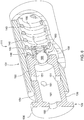
- the coupler 119 translates a rotational force and comprises a first rotational element 116 and a second rotational element 118.
- the first rotational element 116 defines a first pocket 182, and the second rotational element 118-which is in rotational alignment therewith-defines a second pocket 184 facing the first pocket 182, both of which may be machined into place with a milling machine or cutter.
- the first and second pockets 182, 184 define a dampening chamber 186 therebetween that varies in volume based on the overlap thereof.
- a fluid is positioned in the dampening chamber 186. A portion of the fluid is dispelled therefrom when the first rotational element 116 rotates relative to the second rotational element 118, causing a decrease in the volume of the dampening chamber 186.
- the camshaft 114 may include a camshaft supply passage 158.
- the first rotational element 116 may include a first supply passage 179 positioned downstream of the camshaft supply passage 158, but upstream of the dampening chamber 186.
- An inlet 181 of the first supply passage 179 may be positioned at an inner circumferential surface 170 of the first rotational element 116, and an outlet 183 of the first supply passage 179 may be positioned at an outer circumferential surface 168 of the hub 174 of the first rotational element 116.
- the first rotational element 116 and the second rotational element 118 may cooperate, so as to define a second supply passage 185 positioned fluidly downstream of the first supply passage 179.
- An inlet 187 of the second supply passage 185 may be positioned at an inner circumferential surface 172 of the second rotational element 118, and an outlet 189 of the second supply passage 185 may open into the axial aperture 150.
- the second supply passage 185 is shown as having an L-shape, but could take various shapes and paths between the inlet 187 and the outlet 189.
- the coupler 119 may include a dampener 111 positioned in the dampening chamber 186, which may include a plunger receiver 131, a plunger 129 (positioned at least partially therein), and an elastic member 140.
- the dampener 111 is shown as being straight (about a single axis), but in other embodiments, the dampener 111 (and the components thereof) may be arced about an axis of the first and second rotational elements 116, 118.
- the first supply passage 179, the second supply passage 185, and the dampener 111 are shown in four locations spaced equidistantly about the axis of the first and second rotational elements 116, 118. The number and spacing of these components may vary, depending on coupler 119 and its application.
- the elastic member 140 may be positioned in the dampening chamber 186, so as to urge the pockets 182, 184 into rotational alignment with one another. But as the elastic member 140 is compressed a portion of the fluid is dispelled from the dampening chamber 186. The elastic member 140 and the dispelling of the fluid may absorb the fluctuating torque caused by the fuel pump 128 and dampen the torsional vibrations in the engine drivetrain 107.
- the first pocket 182 When the dampener 111 is in a fully extended position, the first pocket 182 may mirror and align with the second pocket 184. And when the dampener 111 is not in the fully extended position, the first pocket 182 may be offset from the second pocket 184.
- the plunger 129 may include a plunger cap 136 and a plunger cylinder 138 extending therefrom.
- An outer circumferential surface 141 of the plunger cap 136 may have a larger diameter than an outer circumferential surface 143 of the plunger cylinder 138.
- the outer circumferential surface 141 of the plunger cap 136 may contact and reciprocate on an inner circumferential surface 148 of the dampening chamber 186.
- the plunger receiver 131 may include a radially inward mating surface 154 that contacts the plunger cylinder 138, and the plunger 129 may reciprocate on the radially inward mating surface 154.
- the plunger cap 136 may include an axial aperture 150 that opens into the plunger cylinder 138, which may include a radial aperture 151 positioned fluidly between the axial aperture 150 and the dampening chamber 186. As illustrated, the radial aperture 151 may be one of a plurality of radial apertures 151.
- the plunger cap 136 and the plunger cylinder 138 may define a reversing flow chamber 161 positioned fluidly between the axial aperture 150 and the radial aperture 151.
- the plunger 129 may include a rapid flow base 146 on an opposite end of the plunger 129 relative to an end having the plunger cap 136.
- the plunger receiver 131 and the rapid flow base 146 define a plunging chamber 156 therebetween that varies in volume as the first rotational element 116 rotates relative to the second rotational element 118.
- An outer surface of the plunger 129 and an inner surface of the plunger receiver 131 may define an annular flow passage 190 positioned therebetween.
- the axial aperture 150 may be positioned fluidly between the second supply passage 185 and the reversing flow chamber 161.
- the reversing flow chamber 161 may be positioned fluidly between the axial aperture 150 and the radial aperture 151.
- the radial aperture 151 may be positioned fluidly between the reversing flow chamber 161 and the annular flow passage 190.
- the annular flow passage 190 may be positioned fluidly between the radial aperture 151 and the plunging chamber 156.
- the rapid flow base 146 may include a rapid flow check valve 159 positioned fluidly between the reversing flow chamber 161 and the plunging chamber 156.
- the rapid flow check valve 159 opens, in a first mode, so as to allow the fluid to flow from the reversing flow chamber 161 and quickly to the plunging chamber 156, but does not open so as to allow the fluid to flow from the plunging chamber 156 to the reversing flow chamber 161. Additionally, in the first mode, the fluid may enter the plunging chamber 156 by flowing through the axial aperture 150, the reversing chamber, the radial aperture 151, and then the annular flow passage 190.
- the rapid flow check valve 159 may include a flow controller 169, an elastic valve member 171, and a valve cage 173.
- the elastic valve member 171 may be sandwiched between the flow controller 169 and the valve cage 173.
- the valve cage 173 may be sandwiched between the flow controller 169 and the valve cage 173.
- the valve cage 173 may include an axial valve aperture 177 and a radial valve aperture 180.
- the radial valve aperture 180 may be one of a plurality of radial valve apertures 180.
- the valve cage 173 may be welded to the plunger cylinder 138 and is positioned fluidly between the reversing flow chamber 161 and the plunging chamber 156.
- the fluid may dispel from the plunging chamber 156 in a second mode by flowing through the annular flow passage 190, the radial aperture 151, the reversing chamber, and the axial aperture 150. This may occur when the first pocket 182 rotates relative to the second pocket 184, so as to decrease the volume of the dampening chamber 186 and the plunging chamber 156. Then, the fluid is dispelled from the axial aperture 150 through a radially outer annular passage 167, formed by an inner side 175 of the first rotational element 116 and an inner side 176 of the second rotational element 118. The fluid then may sling out onto other components of the engine drivetrain 107 and then recirculate back to the coupler 119 and other components of the engine 106.
Landscapes
- Engineering & Computer Science (AREA)
- General Engineering & Computer Science (AREA)
- Mechanical Engineering (AREA)
- Physics & Mathematics (AREA)
- Acoustics & Sound (AREA)
- Aviation & Aerospace Engineering (AREA)
- Chemical & Material Sciences (AREA)
- Combustion & Propulsion (AREA)
- Fuel-Injection Apparatus (AREA)
- Valve Device For Special Equipments (AREA)
- Rotary Pumps (AREA)
Claims (13)
- Koppler (119) zur Übertragung einer Drehkraft, der Folgendes umfasst:ein erstes Drehelement (116), das eine erste Tasche (182) definiert;ein zweites Drehelement (118) in axialer Ausrichtung auf das erste Drehelement (116), das eine zweite Tasche (184) definiert, die zu der ersten Tasche (182) weist, wobei die erste Tasche (182) und die zweite Tasche (184) eine Dämpfungskammer dazwischen definieren, deren Volumen basierend auf einer Überlagerung davon variiert; undein Fluid, das in der Dämpfungskammer positioniert ist, wobei ein Teil des Fluids aus der Dämpfungskammer verdrängt wird, wenn sich das erste Drehelement (116) bezüglich des zweiten Drehelements (118) dreht und das Volumen der Dämpfungskammer verringert,dadurch gekennzeichnet, dass der Koppler (119) ferner Folgendes umfasst: eine Dämpfungsvorrichtung (111), die in der Dämpfungskammer positioniert ist;eine Kolbenaufnahmevorrichtung (131);einen Kolben (129), der zumindest zum Teil darin positioniert ist; undein elastisches Glied (140), wobei die Kolbenaufnahmevorrichtung (131) in Kontakt mit einem Ende des elastischen Glieds (140) positioniert ist, wobei der Teil des Fluids verdrängt wird, wenn das elastische Glied (140) zusammengedrückt wird, undwobei die erste Tasche (182) zur zweiten Tasche (184) symmetrisch und darauf ausgerichtet ist, wenn sich die Dämpfungsvorrichtung (111) in einer vollständig ausgedehnten Stellung befindet, und die erste Tasche (182) von der zweiten Tasche (184) versetzt ist, wenn sich die Dämpfungsvorrichtung (111) nicht in der vollständig ausgedehnten Stellung befindet.
- Koppler (119) nach Anspruch 1, der ferner ein elastisches Glied (140) umfasst, das in der Dämpfungskammer positioniert und dazu konfiguriert ist, die erste Tasche (182) und die zweite Tasche (184) dazu zu bringen, zueinander symmetrisch und aufeinander ausgerichtet zu sein, wobei der Teil des Fluids verdrängt wird, wenn das elastische Glied (140) zusammengedrückt wird.
- Koppler (119) nach Anspruch 1 oder 2, wobei das Fluid durch einen äußeren Ringkanal (167), der durch eine innere Seite des ersten Drehelements (116) und eine innere Seite des zweiten Drehelements (118) gebildet wird, aus der Dämpfungskammer verdrängt wird.
- Koppler (119) nach einem der Ansprüche 1-3, wobei das erste Drehelement (116) einen ersten Zufuhrkanal (179), der strömungstechnisch stromaufwärts der Dämpfungskammer positioniert ist, umfasst, ein Einlass (181) des ersten Zufuhrkanals (179) auf einer Innenumfangsfläche des ersten Drehelements (116) positioniert ist und ein Auslass des ersten Zufuhrkanals (179) auf einer Außenumfangsfläche des ersten Drehelements (116) positioniert ist.
- Koppler nach Anspruch 1, wobei der Kolben (129) eine Kolbenkappe (136) und einen Kolbenzylinder (138), der sich davon erstreckt, umfasst, eine Außenumfangsfläche der Kolbenkappe (136) einen größeren Durchmesser als eine Außenumfangsfläche des Kolbenzylinders (138) aufweist, die Außenumfangsfläche der Kolbenkappe (136) eine Innenumfangsfläche der Dämpfungskammer berührt und sich darauf hin und her bewegt.
- Koppler (119) nach einem der Ansprüche 1-5, wobei die Kolbenaufnahmevorrichtung (131) eine radial innere Passfläche umfasst, die den Kolbenzylinder (138) berührt, und sich der Kolben (129) auf der radial inneren Passfläche hin und her bewegt.
- Koppler (119) nach einem der Ansprüche 1-5, wobei der Kolben (129) eine Kolbenkappe (136) und einen Kolbenzylinder (138), der sich davon erstreckt, umfasst, die Kolbenkappe (136) eine axiale Öffnung (150) umfasst, die in den Kolbenzylinder (138) mündet, der Kolbenzylinder (138) eine radiale Öffnung (151) umfasst, die strömungstechnisch zwischen der axialen Öffnung (150) und der Dämpfungskammer positioniert ist.
- Koppler (119) nach einem der Ansprüche 1-7, wobei:das erste Drehelement (116) einen ersten Zufuhrkanal (179) umfasst, der strömungstechnisch stromaufwärts der Dämpfungskammer positioniert ist, ein Einlass (181) des ersten Zufuhrkanals (179) auf einer Innenumfangsfläche des ersten Drehelements (116) positioniert ist und ein Auslass (183) des ersten Zufuhrkanals (179) auf einer Außenumfangsfläche einer Nabe des ersten Drehelements (116) positioniert ist; unddas erste Drehelement (116) und das zweite Drehelement (118) einen zweiten Zufuhrkanal (185) definieren, der strömungstechnisch stromabwärts des ersten Zufuhrkanals (179) positioniert ist, ein Einlass (187) des zweiten Zufuhrkanals (185) auf einer Innenumfangsfläche des zweiten Drehelements (118) positioniert ist und ein Auslass (189) des zweiten Zufuhrkanals (185) in die axiale Öffnung (150) mündet.
- Koppler (119) nach einem der Ansprüche 5-8, wobei die Kolbenkappe (136) und der Kolbenzylinder (138) eine Umkehrströmungskammer definieren, die strömungstechnisch zwischen der axialen Öffnung (150) und der radialen Öffnung (151) positioniert ist.
- Koppler (119) nach einem der Ansprüche 5-9, wobei der Kolben (129) eine Schnellströmungsbasis (146) an einem gegenüberliegenden Ende des Kolbens (129) bezüglich einem Ende mit der Kolbenkappe (136) umfasst, die Kolbenaufnahmevorrichtung (131) und die Schnellströmungsbasis (146) eine Kolbenkammer dazwischen definieren, deren Volumen mit Drehung des ersten Drehelements (116) bezüglich des zweiten Drehelements (118) variiert.
- Koppler (119) nach einem der Ansprüche 1-10, wobei eine Außenfläche des Kolbens (129) und eine Innenfläche der Kolbenaufnahmevorrichtung (131) einen ringförmigen Strömungskanal (190) definieren, der dazwischen positioniert ist, der ringförmige Strömungskanal (190) strömungstechnisch zwischen der radialen Öffnung (151) und der Kolbenkammer positioniert ist, das Fluid in einem ersten Modus in die Kolbenkammer eintritt, indem es durch den ringförmigen Strömungskanal (190) strömt, und das Fluid in einem zweiten Modus aus der Kolbenkammer verdrängt wird, in dem es durch den ringförmigen Strömungskanal (190) strömt, wenn sich die erste Tasche (182) bezüglich der zweiten Tasche (184) dreht und das Volumen der Dämpfungskammer und der Kolbenkammer verringert.
- Motortriebstrang (107), der ferner den Koppler (119) nach einem der Ansprüche 1-11 umfasst, wobei der Motortriebstrang (107) eine Nockenwelle (114) umfasst, der Koppler (119) um die Nockenwelle (114) herum befestigt und zur Drehung damit fixiert ist, das erste Drehelement (116) mit einem Kurbelwellenrad (112) kämmt und das zweite Drehelement (118) mit einem Kraftstoffpumpenrad (126) kämmt.
- Motortriebstrang (107) nach Anspruch 12, wobei:die Nockenwelle (114) einen Nockenwellenzufuhrkanal (158) umfasst; unddas erste Drehelement (116) einen ersten Zufuhrkanal (179) umfasst, der stromabwärts des Nockenwellenzufuhrkanals (158) positioniert ist und strömungstechnisch stromaufwärts der Dämpfungskammer positioniert ist, ein Einlass (181) des ersten Zufuhrkanals (179) auf einer Innenumfangsfläche des ersten Drehelements (116) positioniert ist und ein Auslass (183) des ersten Zufuhrkanals (179) auf einer Außenumfangsfläche des ersten Drehelements (116) positioniert ist.
Applications Claiming Priority (1)
| Application Number | Priority Date | Filing Date | Title |
|---|---|---|---|
| US14/593,006 US9664251B2 (en) | 2015-01-09 | 2015-01-09 | Coupler for translating rotational forces |
Publications (2)
| Publication Number | Publication Date |
|---|---|
| EP3043035A1 EP3043035A1 (de) | 2016-07-13 |
| EP3043035B1 true EP3043035B1 (de) | 2018-06-06 |
Family
ID=55066298
Family Applications (1)
| Application Number | Title | Priority Date | Filing Date |
|---|---|---|---|
| EP15199113.0A Not-in-force EP3043035B1 (de) | 2015-01-09 | 2015-12-10 | Koppler zur übertragung von drehkräften |
Country Status (2)
| Country | Link |
|---|---|
| US (1) | US9664251B2 (de) |
| EP (1) | EP3043035B1 (de) |
Families Citing this family (6)
| Publication number | Priority date | Publication date | Assignee | Title |
|---|---|---|---|---|
| KR101646120B1 (ko) * | 2014-12-03 | 2016-08-05 | 현대자동차 주식회사 | 모터 커플링 장치 |
| DE102016202178B4 (de) | 2016-02-12 | 2024-04-25 | Bayerische Motoren Werke Aktiengesellschaft | Vorrichtung zum Reduzieren von Drehschwingungen in einem Antriebsstrang und Verfahren zum Betrieb einer solchen Vorrichtung |
| US20190011013A1 (en) * | 2017-07-07 | 2019-01-10 | GM Global Technology Operations LLC | Active vibration damper for a vehicle driveline component |
| USD1076983S1 (en) * | 2020-06-29 | 2025-05-27 | Powerhouse Engine Solutions Switzerland IP Holding GmbH | Timing wheel |
| US11530733B2 (en) | 2020-11-03 | 2022-12-20 | Hamilton Sundstrand Corporation | Integrated hydraulic damper for torsional oscillation reduction |
| US12345309B1 (en) * | 2024-03-25 | 2025-07-01 | Ante Puljic | Gravitational torque amplifier apparatus and method |
Family Cites Families (12)
| Publication number | Priority date | Publication date | Assignee | Title |
|---|---|---|---|---|
| US1734043A (en) * | 1928-02-09 | 1929-11-05 | Carl E Nelson | Hydraulic flexible coupling |
| DE3502029A1 (de) | 1985-01-23 | 1986-07-31 | Fichtel & Sachs Ag, 8720 Schweinfurt | Torsionsdaempfer fuer kupplungsscheiben mit hydraulischer daempfung |
| DE3639190A1 (de) * | 1986-11-15 | 1988-05-26 | Freudenberg Carl Fa | Drehschwingungsdaempfer |
| SE464930B (sv) * | 1989-09-20 | 1991-07-01 | Volvo Ab | Svaenghjul foer foerbraenningsmotorer |
| DE4345346C2 (de) * | 1992-10-30 | 2001-04-05 | Exedy Corp | Kupplungsscheibenausbildung |
| JPH1182041A (ja) | 1997-09-01 | 1999-03-26 | Suzuki Motor Corp | 内燃機関の動力伝達装置 |
| DE19909914B4 (de) | 1999-03-06 | 2004-09-09 | Mtu Friedrichshafen Gmbh | Hydraulisches Dämpfungselement |
| KR100569389B1 (ko) | 2003-10-07 | 2006-04-07 | 현대자동차주식회사 | 차량용 캠간 구동시스템의 유압식 백래쉬 제거 장치 |
| DE102009045610A1 (de) * | 2009-10-13 | 2011-05-05 | Zf Friedrichshafen Ag | Nasslaufende Kupplungsanordnung |
| TW201204964A (en) | 2010-07-23 | 2012-02-01 | Kwang Yang Motor Co | Backlash eliminator with lubricant |
| CN102072309A (zh) | 2011-01-29 | 2011-05-25 | 重庆长安汽车股份有限公司 | 一种带润滑油孔的发动机从动齿轮总成 |
| DE102012211526A1 (de) | 2012-07-03 | 2014-01-09 | Schaeffler Technologies AG & Co. KG | Hydraulischer Nockenwellenversteller mit interner Dämpfung |
-
2015
- 2015-01-09 US US14/593,006 patent/US9664251B2/en not_active Expired - Fee Related
- 2015-12-10 EP EP15199113.0A patent/EP3043035B1/de not_active Not-in-force
Non-Patent Citations (1)
| Title |
|---|
| None * |
Also Published As
| Publication number | Publication date |
|---|---|
| US9664251B2 (en) | 2017-05-30 |
| US20160201758A1 (en) | 2016-07-14 |
| EP3043035A1 (de) | 2016-07-13 |
Similar Documents
| Publication | Publication Date | Title |
|---|---|---|
| EP3043035B1 (de) | Koppler zur übertragung von drehkräften | |
| US5154147A (en) | Rotary valve | |
| EP2816203B1 (de) | Nockenwellenversteller | |
| JP2003003927A (ja) | 燃料噴射ポンプ | |
| US8801396B2 (en) | Oil pump system for an engine | |
| US11111893B2 (en) | Tappet assembly for use in a high-pressure fuel system of an internal combustion engine | |
| JP2006153005A (ja) | 偏心クランク可変圧縮比機構 | |
| US10697413B2 (en) | Tappet assembly for use in a high-pressure fuel system of an internal combustion engine | |
| WO2012074610A1 (en) | Cam shaft/cam gear assembly and thrust strategy for engine using same | |
| US10837416B2 (en) | Tappet assembly for use in a high-pressure fuel system of an internal combustion engine | |
| EP3060775B1 (de) | Turbocompoundeinheit | |
| JP5908364B2 (ja) | 内燃機関の油路構造 | |
| EP1767771B1 (de) | Hochdruck-Kraftstoffförderpumpe | |
| EP1939414B1 (de) | Dichtung für ein Ventil in einem Verbrennungsmotor | |
| US20110129359A1 (en) | Variable output pump | |
| CA2542028C (en) | Internal combustion engine with torque converter | |
| JP2015517626A (ja) | 内燃エンジン | |
| JP2010216262A (ja) | 燃料噴射ポンプ | |
| EA030441B1 (ru) | Составное уплотнение для роторно-поршневого двигателя внутреннего сгорания | |
| US9181909B2 (en) | Fuel pump retainer | |
| AU2021329294B2 (en) | Head assembly with rotary valves for an internal combustion engine | |
| CN211082533U (zh) | 曲轴外置全支撑结构 | |
| US8944022B2 (en) | Pump assembly for internal combustion engine | |
| EP3714176B1 (de) | Turbolader für einen verbrennungsmotor | |
| JP4606386B2 (ja) | 回転角センサを備える機械または内燃機関 |
Legal Events
| Date | Code | Title | Description |
|---|---|---|---|
| PUAI | Public reference made under article 153(3) epc to a published international application that has entered the european phase |
Free format text: ORIGINAL CODE: 0009012 |
|
| AK | Designated contracting states |
Kind code of ref document: A1 Designated state(s): AL AT BE BG CH CY CZ DE DK EE ES FI FR GB GR HR HU IE IS IT LI LT LU LV MC MK MT NL NO PL PT RO RS SE SI SK SM TR |
|
| AX | Request for extension of the european patent |
Extension state: BA ME |
|
| 17P | Request for examination filed |
Effective date: 20170113 |
|
| RBV | Designated contracting states (corrected) |
Designated state(s): AL AT BE BG CH CY CZ DE DK EE ES FI FR GB GR HR HU IE IS IT LI LT LU LV MC MK MT NL NO PL PT RO RS SE SI SK SM TR |
|
| 17Q | First examination report despatched |
Effective date: 20170406 |
|
| GRAP | Despatch of communication of intention to grant a patent |
Free format text: ORIGINAL CODE: EPIDOSNIGR1 |
|
| RIC1 | Information provided on ipc code assigned before grant |
Ipc: F16F 15/16 20060101ALI20171205BHEP Ipc: F01L 1/02 20060101AFI20171205BHEP Ipc: F16F 15/121 20060101ALI20171205BHEP Ipc: F16H 45/02 20060101ALI20171205BHEP Ipc: F02B 75/06 20060101ALN20171205BHEP |
|
| INTG | Intention to grant announced |
Effective date: 20180103 |
|
| GRAS | Grant fee paid |
Free format text: ORIGINAL CODE: EPIDOSNIGR3 |
|
| GRAA | (expected) grant |
Free format text: ORIGINAL CODE: 0009210 |
|
| AK | Designated contracting states |
Kind code of ref document: B1 Designated state(s): AL AT BE BG CH CY CZ DE DK EE ES FI FR GB GR HR HU IE IS IT LI LT LU LV MC MK MT NL NO PL PT RO RS SE SI SK SM TR |
|
| REG | Reference to a national code |
Ref country code: GB Ref legal event code: FG4D |
|
| REG | Reference to a national code |
Ref country code: CH Ref legal event code: EP Ref country code: AT Ref legal event code: REF Ref document number: 1006323 Country of ref document: AT Kind code of ref document: T Effective date: 20180615 |
|
| REG | Reference to a national code |
Ref country code: IE Ref legal event code: FG4D |
|
| REG | Reference to a national code |
Ref country code: DE Ref legal event code: R096 Ref document number: 602015011754 Country of ref document: DE |
|
| REG | Reference to a national code |
Ref country code: NL Ref legal event code: MP Effective date: 20180606 |
|
| REG | Reference to a national code |
Ref country code: LT Ref legal event code: MG4D |
|
| PG25 | Lapsed in a contracting state [announced via postgrant information from national office to epo] |
Ref country code: ES Free format text: LAPSE BECAUSE OF FAILURE TO SUBMIT A TRANSLATION OF THE DESCRIPTION OR TO PAY THE FEE WITHIN THE PRESCRIBED TIME-LIMIT Effective date: 20180606 Ref country code: SE Free format text: LAPSE BECAUSE OF FAILURE TO SUBMIT A TRANSLATION OF THE DESCRIPTION OR TO PAY THE FEE WITHIN THE PRESCRIBED TIME-LIMIT Effective date: 20180606 Ref country code: LT Free format text: LAPSE BECAUSE OF FAILURE TO SUBMIT A TRANSLATION OF THE DESCRIPTION OR TO PAY THE FEE WITHIN THE PRESCRIBED TIME-LIMIT Effective date: 20180606 Ref country code: BG Free format text: LAPSE BECAUSE OF FAILURE TO SUBMIT A TRANSLATION OF THE DESCRIPTION OR TO PAY THE FEE WITHIN THE PRESCRIBED TIME-LIMIT Effective date: 20180906 Ref country code: FI Free format text: LAPSE BECAUSE OF FAILURE TO SUBMIT A TRANSLATION OF THE DESCRIPTION OR TO PAY THE FEE WITHIN THE PRESCRIBED TIME-LIMIT Effective date: 20180606 Ref country code: NO Free format text: LAPSE BECAUSE OF FAILURE TO SUBMIT A TRANSLATION OF THE DESCRIPTION OR TO PAY THE FEE WITHIN THE PRESCRIBED TIME-LIMIT Effective date: 20180906 Ref country code: CY Free format text: LAPSE BECAUSE OF FAILURE TO SUBMIT A TRANSLATION OF THE DESCRIPTION OR TO PAY THE FEE WITHIN THE PRESCRIBED TIME-LIMIT Effective date: 20180606 |
|
| PG25 | Lapsed in a contracting state [announced via postgrant information from national office to epo] |
Ref country code: LV Free format text: LAPSE BECAUSE OF FAILURE TO SUBMIT A TRANSLATION OF THE DESCRIPTION OR TO PAY THE FEE WITHIN THE PRESCRIBED TIME-LIMIT Effective date: 20180606 Ref country code: RS Free format text: LAPSE BECAUSE OF FAILURE TO SUBMIT A TRANSLATION OF THE DESCRIPTION OR TO PAY THE FEE WITHIN THE PRESCRIBED TIME-LIMIT Effective date: 20180606 Ref country code: HR Free format text: LAPSE BECAUSE OF FAILURE TO SUBMIT A TRANSLATION OF THE DESCRIPTION OR TO PAY THE FEE WITHIN THE PRESCRIBED TIME-LIMIT Effective date: 20180606 Ref country code: GR Free format text: LAPSE BECAUSE OF FAILURE TO SUBMIT A TRANSLATION OF THE DESCRIPTION OR TO PAY THE FEE WITHIN THE PRESCRIBED TIME-LIMIT Effective date: 20180907 |
|
| REG | Reference to a national code |
Ref country code: AT Ref legal event code: MK05 Ref document number: 1006323 Country of ref document: AT Kind code of ref document: T Effective date: 20180606 |
|
| PG25 | Lapsed in a contracting state [announced via postgrant information from national office to epo] |
Ref country code: NL Free format text: LAPSE BECAUSE OF FAILURE TO SUBMIT A TRANSLATION OF THE DESCRIPTION OR TO PAY THE FEE WITHIN THE PRESCRIBED TIME-LIMIT Effective date: 20180606 |
|
| PG25 | Lapsed in a contracting state [announced via postgrant information from national office to epo] |
Ref country code: SK Free format text: LAPSE BECAUSE OF FAILURE TO SUBMIT A TRANSLATION OF THE DESCRIPTION OR TO PAY THE FEE WITHIN THE PRESCRIBED TIME-LIMIT Effective date: 20180606 Ref country code: EE Free format text: LAPSE BECAUSE OF FAILURE TO SUBMIT A TRANSLATION OF THE DESCRIPTION OR TO PAY THE FEE WITHIN THE PRESCRIBED TIME-LIMIT Effective date: 20180606 Ref country code: IS Free format text: LAPSE BECAUSE OF FAILURE TO SUBMIT A TRANSLATION OF THE DESCRIPTION OR TO PAY THE FEE WITHIN THE PRESCRIBED TIME-LIMIT Effective date: 20181006 Ref country code: PL Free format text: LAPSE BECAUSE OF FAILURE TO SUBMIT A TRANSLATION OF THE DESCRIPTION OR TO PAY THE FEE WITHIN THE PRESCRIBED TIME-LIMIT Effective date: 20180606 Ref country code: AT Free format text: LAPSE BECAUSE OF FAILURE TO SUBMIT A TRANSLATION OF THE DESCRIPTION OR TO PAY THE FEE WITHIN THE PRESCRIBED TIME-LIMIT Effective date: 20180606 Ref country code: RO Free format text: LAPSE BECAUSE OF FAILURE TO SUBMIT A TRANSLATION OF THE DESCRIPTION OR TO PAY THE FEE WITHIN THE PRESCRIBED TIME-LIMIT Effective date: 20180606 Ref country code: CZ Free format text: LAPSE BECAUSE OF FAILURE TO SUBMIT A TRANSLATION OF THE DESCRIPTION OR TO PAY THE FEE WITHIN THE PRESCRIBED TIME-LIMIT Effective date: 20180606 |
|
| PG25 | Lapsed in a contracting state [announced via postgrant information from national office to epo] |
Ref country code: IT Free format text: LAPSE BECAUSE OF FAILURE TO SUBMIT A TRANSLATION OF THE DESCRIPTION OR TO PAY THE FEE WITHIN THE PRESCRIBED TIME-LIMIT Effective date: 20180606 Ref country code: SM Free format text: LAPSE BECAUSE OF FAILURE TO SUBMIT A TRANSLATION OF THE DESCRIPTION OR TO PAY THE FEE WITHIN THE PRESCRIBED TIME-LIMIT Effective date: 20180606 |
|
| REG | Reference to a national code |
Ref country code: DE Ref legal event code: R097 Ref document number: 602015011754 Country of ref document: DE |
|
| PLBE | No opposition filed within time limit |
Free format text: ORIGINAL CODE: 0009261 |
|
| STAA | Information on the status of an ep patent application or granted ep patent |
Free format text: STATUS: NO OPPOSITION FILED WITHIN TIME LIMIT |
|
| 26N | No opposition filed |
Effective date: 20190307 |
|
| PG25 | Lapsed in a contracting state [announced via postgrant information from national office to epo] |
Ref country code: DK Free format text: LAPSE BECAUSE OF FAILURE TO SUBMIT A TRANSLATION OF THE DESCRIPTION OR TO PAY THE FEE WITHIN THE PRESCRIBED TIME-LIMIT Effective date: 20180606 Ref country code: SI Free format text: LAPSE BECAUSE OF FAILURE TO SUBMIT A TRANSLATION OF THE DESCRIPTION OR TO PAY THE FEE WITHIN THE PRESCRIBED TIME-LIMIT Effective date: 20180606 |
|
| REG | Reference to a national code |
Ref country code: CH Ref legal event code: PL |
|
| PG25 | Lapsed in a contracting state [announced via postgrant information from national office to epo] |
Ref country code: LU Free format text: LAPSE BECAUSE OF NON-PAYMENT OF DUE FEES Effective date: 20181210 Ref country code: MC Free format text: LAPSE BECAUSE OF FAILURE TO SUBMIT A TRANSLATION OF THE DESCRIPTION OR TO PAY THE FEE WITHIN THE PRESCRIBED TIME-LIMIT Effective date: 20180606 |
|
| REG | Reference to a national code |
Ref country code: IE Ref legal event code: MM4A |
|
| REG | Reference to a national code |
Ref country code: BE Ref legal event code: MM Effective date: 20181231 |
|
| PG25 | Lapsed in a contracting state [announced via postgrant information from national office to epo] |
Ref country code: IE Free format text: LAPSE BECAUSE OF NON-PAYMENT OF DUE FEES Effective date: 20181210 Ref country code: FR Free format text: LAPSE BECAUSE OF NON-PAYMENT OF DUE FEES Effective date: 20181231 |
|
| PG25 | Lapsed in a contracting state [announced via postgrant information from national office to epo] |
Ref country code: BE Free format text: LAPSE BECAUSE OF NON-PAYMENT OF DUE FEES Effective date: 20181231 Ref country code: AL Free format text: LAPSE BECAUSE OF FAILURE TO SUBMIT A TRANSLATION OF THE DESCRIPTION OR TO PAY THE FEE WITHIN THE PRESCRIBED TIME-LIMIT Effective date: 20180606 |
|
| PG25 | Lapsed in a contracting state [announced via postgrant information from national office to epo] |
Ref country code: LI Free format text: LAPSE BECAUSE OF NON-PAYMENT OF DUE FEES Effective date: 20181231 Ref country code: CH Free format text: LAPSE BECAUSE OF NON-PAYMENT OF DUE FEES Effective date: 20181231 |
|
| PG25 | Lapsed in a contracting state [announced via postgrant information from national office to epo] |
Ref country code: MT Free format text: LAPSE BECAUSE OF NON-PAYMENT OF DUE FEES Effective date: 20181210 |
|
| PGFP | Annual fee paid to national office [announced via postgrant information from national office to epo] |
Ref country code: DE Payment date: 20191120 Year of fee payment: 5 |
|
| PG25 | Lapsed in a contracting state [announced via postgrant information from national office to epo] |
Ref country code: TR Free format text: LAPSE BECAUSE OF FAILURE TO SUBMIT A TRANSLATION OF THE DESCRIPTION OR TO PAY THE FEE WITHIN THE PRESCRIBED TIME-LIMIT Effective date: 20180606 |
|
| PGFP | Annual fee paid to national office [announced via postgrant information from national office to epo] |
Ref country code: GB Payment date: 20191227 Year of fee payment: 5 |
|
| PG25 | Lapsed in a contracting state [announced via postgrant information from national office to epo] |
Ref country code: PT Free format text: LAPSE BECAUSE OF FAILURE TO SUBMIT A TRANSLATION OF THE DESCRIPTION OR TO PAY THE FEE WITHIN THE PRESCRIBED TIME-LIMIT Effective date: 20180606 |
|
| PG25 | Lapsed in a contracting state [announced via postgrant information from national office to epo] |
Ref country code: HU Free format text: LAPSE BECAUSE OF FAILURE TO SUBMIT A TRANSLATION OF THE DESCRIPTION OR TO PAY THE FEE WITHIN THE PRESCRIBED TIME-LIMIT; INVALID AB INITIO Effective date: 20151210 Ref country code: MK Free format text: LAPSE BECAUSE OF NON-PAYMENT OF DUE FEES Effective date: 20180606 |
|
| REG | Reference to a national code |
Ref country code: DE Ref legal event code: R119 Ref document number: 602015011754 Country of ref document: DE |
|
| GBPC | Gb: european patent ceased through non-payment of renewal fee |
Effective date: 20201210 |
|
| PG25 | Lapsed in a contracting state [announced via postgrant information from national office to epo] |
Ref country code: DE Free format text: LAPSE BECAUSE OF NON-PAYMENT OF DUE FEES Effective date: 20210701 Ref country code: GB Free format text: LAPSE BECAUSE OF NON-PAYMENT OF DUE FEES Effective date: 20201210 |