EP3041694B1 - Heiz-/kühlsystem für fahrzeuge und verfahren zum betreiben eines heiz-/ kühlsystems für fahrzeuge - Google Patents
Heiz-/kühlsystem für fahrzeuge und verfahren zum betreiben eines heiz-/ kühlsystems für fahrzeuge Download PDFInfo
- Publication number
- EP3041694B1 EP3041694B1 EP14752608.1A EP14752608A EP3041694B1 EP 3041694 B1 EP3041694 B1 EP 3041694B1 EP 14752608 A EP14752608 A EP 14752608A EP 3041694 B1 EP3041694 B1 EP 3041694B1
- Authority
- EP
- European Patent Office
- Prior art keywords
- refrigerant
- evaporator
- circuit
- condenser
- heat exchanger
- Prior art date
- Legal status (The legal status is an assumption and is not a legal conclusion. Google has not performed a legal analysis and makes no representation as to the accuracy of the status listed.)
- Active
Links
Images


Classifications
-
- B—PERFORMING OPERATIONS; TRANSPORTING
- B60—VEHICLES IN GENERAL
- B60H—ARRANGEMENTS OF HEATING, COOLING, VENTILATING OR OTHER AIR-TREATING DEVICES SPECIALLY ADAPTED FOR PASSENGER OR GOODS SPACES OF VEHICLES
- B60H1/00—Heating, cooling or ventilating devices
- B60H1/00642—Control systems or circuits; Control members or indication devices for heating, cooling or ventilating devices
- B60H1/00814—Control systems or circuits characterised by their output, for controlling particular components of the heating, cooling or ventilating installation
- B60H1/00878—Control systems or circuits characterised by their output, for controlling particular components of the heating, cooling or ventilating installation the components being temperature regulating devices
- B60H1/00899—Controlling the flow of liquid in a heat pump system
- B60H1/00907—Controlling the flow of liquid in a heat pump system where the flow direction of the refrigerant changes and an evaporator becomes condenser
-
- B—PERFORMING OPERATIONS; TRANSPORTING
- B60—VEHICLES IN GENERAL
- B60H—ARRANGEMENTS OF HEATING, COOLING, VENTILATING OR OTHER AIR-TREATING DEVICES SPECIALLY ADAPTED FOR PASSENGER OR GOODS SPACES OF VEHICLES
- B60H1/00—Heating, cooling or ventilating devices
- B60H1/32—Cooling devices
- B60H1/3204—Cooling devices using compression
- B60H1/3228—Cooling devices using compression characterised by refrigerant circuit configurations
- B60H1/32284—Cooling devices using compression characterised by refrigerant circuit configurations comprising two or more secondary circuits, e.g. at evaporator and condenser side
-
- B—PERFORMING OPERATIONS; TRANSPORTING
- B60—VEHICLES IN GENERAL
- B60H—ARRANGEMENTS OF HEATING, COOLING, VENTILATING OR OTHER AIR-TREATING DEVICES SPECIALLY ADAPTED FOR PASSENGER OR GOODS SPACES OF VEHICLES
- B60H1/00—Heating, cooling or ventilating devices
- B60H1/00642—Control systems or circuits; Control members or indication devices for heating, cooling or ventilating devices
- B60H1/00814—Control systems or circuits characterised by their output, for controlling particular components of the heating, cooling or ventilating installation
- B60H1/00878—Control systems or circuits characterised by their output, for controlling particular components of the heating, cooling or ventilating installation the components being temperature regulating devices
- B60H2001/00928—Control systems or circuits characterised by their output, for controlling particular components of the heating, cooling or ventilating installation the components being temperature regulating devices comprising a secondary circuit
-
- B—PERFORMING OPERATIONS; TRANSPORTING
- B60—VEHICLES IN GENERAL
- B60H—ARRANGEMENTS OF HEATING, COOLING, VENTILATING OR OTHER AIR-TREATING DEVICES SPECIALLY ADAPTED FOR PASSENGER OR GOODS SPACES OF VEHICLES
- B60H1/00—Heating, cooling or ventilating devices
- B60H1/00642—Control systems or circuits; Control members or indication devices for heating, cooling or ventilating devices
- B60H1/00814—Control systems or circuits characterised by their output, for controlling particular components of the heating, cooling or ventilating installation
- B60H1/00878—Control systems or circuits characterised by their output, for controlling particular components of the heating, cooling or ventilating installation the components being temperature regulating devices
- B60H2001/00957—Control systems or circuits characterised by their output, for controlling particular components of the heating, cooling or ventilating installation the components being temperature regulating devices comprising locations with heat exchange within the refrigerant circuit itself, e.g. cross-, counter-, or parallel heat exchange
-
- B—PERFORMING OPERATIONS; TRANSPORTING
- B60—VEHICLES IN GENERAL
- B60H—ARRANGEMENTS OF HEATING, COOLING, VENTILATING OR OTHER AIR-TREATING DEVICES SPECIALLY ADAPTED FOR PASSENGER OR GOODS SPACES OF VEHICLES
- B60H1/00—Heating, cooling or ventilating devices
- B60H1/00642—Control systems or circuits; Control members or indication devices for heating, cooling or ventilating devices
- B60H1/00814—Control systems or circuits characterised by their output, for controlling particular components of the heating, cooling or ventilating installation
- B60H1/00878—Control systems or circuits characterised by their output, for controlling particular components of the heating, cooling or ventilating installation the components being temperature regulating devices
- B60H2001/00961—Control systems or circuits characterised by their output, for controlling particular components of the heating, cooling or ventilating installation the components being temperature regulating devices comprising means for defrosting outside heat exchangers
Definitions
- the invention relates to a heating / cooling system for vehicles of the heat pump type and to a method for operating such a heating / cooling system.
- Such heating / cooling systems are known in various designs, wherein a refrigerant circuit can be operated as a heat pump and / or as a refrigeration machine.
- the refrigerant circuit comprises at least one compressor, a condenser, an evaporator and an expansion device.
- the main advantage of such a heating / cooling system lies in the possibility of interconnection and utilization of the individual heat sources and heat sinks of a vehicle for heating or cooling the vehicle interior.
- the DE 44 10 057 C2 describes a heat pump circuit in which a refrigerant can absorb heat from an air flow in an evaporator and release heat to an air flow in a condenser.
- the heat pump circuit has a bypass around the condenser, so that at very low outside temperatures to defrost a frozen evaporator, the refrigerant can be fed as hot gas from a compressor directly into the evaporator.
- the condenser is completely bridged by the bypass.
- the WO 2012 075 975 A1 describes a heating / cooling device with a refrigerant circuit which is in a heat exchange via a condenser and via an evaporator, each with a separately designed coolant circuit.
- the coolant circuits interact with other heat exchangers in the vehicle and can be connected to one another for optimal interconnection of the heat sources and heat sinks of a vehicle.
- the WO 2012/084 175 A1 describes an air conditioning system for electric vehicles with a refrigerant circuit which has two heat exchangers overflowing with air and can be coupled to a separate fluid circuit via a third heat exchanger.
- the fluid circuit is in a heat exchange with a heat source of the vehicle, in particular a battery, and has an additional heater.
- the EP 2 110 274 A1 describes a heating / cooling device for vehicles with a heat pump circuit, in which the refrigerant flows through the heat pump circuit in the same direction both in a heating mode and in a cooling mode.
- a heat pump circuit in which the refrigerant flows through the heat pump circuit in the same direction both in a heating mode and in a cooling mode.
- an internal heat exchanger and various surrounding lines are also provided.
- the EP 1 348 920 A2 describes a heat pump for the simultaneous cooling and heating of vehicles with a refrigerant circuit, in which three heat exchangers are provided, each of which can be operated as a condenser or evaporator. Each heat exchanger has a bypass line, so that the refrigerant can, for example, be passed through a first or alternatively through a second heat exchanger acting as an evaporator.
- the US 2011/0284181 A1 shows a refrigerant circuit designed as a heat pump, in which the flow direction of the refrigerant can be changed by means of a switching valve.
- the refrigerant can optionally be passed through a first or a second heat exchanger acting as an evaporator.
- the object of the present invention is therefore to provide a heating / cooling system that enables efficient and rapid temperature control of the vehicle interior and of the vehicle assemblies in vehicles with an electric motor and / or internal combustion engine even at extreme temperatures without a separate additional heating or additional cooling. Furthermore, a method is to be provided with which such a heating / cooling system can be operated. The object is achieved according to the invention by a heating / cooling system with the features of claim 1 and by a method with the features of claim 11.
- the heating / cooling system for a motor vehicle comprises a refrigerant circuit, in particular a refrigerant circuit designed as a heat pump and / or refrigerating machine.
- the refrigerant circuit preferably consists of a main line through which a refrigerant can flow and connects the following components of a refrigerant circuit with one another: at least one compressor, a condenser or gas cooler, an evaporator and an expansion device or expansion valve.
- the condenser can be coupled to a first coolant circuit and the evaporator to a second coolant circuit, so that the refrigerant of the refrigerant circuit in the condenser with a first coolant circuit and in the evaporator with a second coolant circuit in a heat exchange can stand.
- the arrangement of the coolant circuits enables the heating / cooling system to be expanded or extended to all heat sources and heat sinks of a vehicle, even those that are far apart. This is particularly advantageous compared to refrigerant circuits with heat exchangers overflowing with air. This means that all heat sources and heat sinks arranged in a vehicle can be integrated into the heating / cooling system integrated or thermally networked with one another.
- the individual coolant circuits can be designed to be separate and / or connectable to one another, so that further interconnection options arise. Furthermore, this arrangement enables the refrigerant either to be heated by a first coolant circuit and cooled by the second coolant circuit or to be heated or cooled by both coolant circuits at the same time, as required. This enables intensive and rapid heating or cooling of the refrigerant. In addition, against the background of the high prices for refrigerants, another advantage is that the amount of refrigerant can be kept relatively small. Furthermore, the number of problem points in a refrigerant circuit can be minimized, in particular the number of possible leakage points can be reduced and high-pressure areas can be reduced.
- the refrigerant circuit has an internal refrigerant heat exchanger which is coupled to the refrigerant of the refrigerant circuit on both sides.
- the internal refrigerant heat exchanger is arranged in the refrigerant circuit on the high-pressure side, preferably between the condenser and the evaporator, and on the low-pressure side between a collecting container and the compressor.
- the refrigerant circuit can also be brought into a self-reinforcing circuit in which the refrigerant in a certain area of the refrigerant circuit, namely downstream of the condenser in heat pump operation and downstream of the evaporator in refrigeration system operation, transfers heat to the refrigerant in another area of the refrigerant -Circuit, namely in heat pump operation to the refrigerant downstream of the evaporator and in refrigeration system operation downstream of the condenser.
- the refrigerant circuit has a switchover valve, in particular a four-way valve, for reversing the direction of flow in the refrigerant circuit.
- the switching valve preferably has two inputs and two outputs.
- the switching valve can, on the one hand, direct the refrigerant flow downstream of the compressor either in a heat pump operation, in particular extreme heating operation, to the condenser or alternatively in a refrigeration system operation to the evaporator and, on the other hand, either in a heat pump operation, the refrigerant flow downstream of the evaporator or downstream of the bypass line to a collecting tank or in a refrigeration system operation, direct the refrigerant flow upstream of the evaporator to a collecting tank.
- the refrigerant circuit can be switched to a heat pump or to a refrigeration system.
- a heat pump mode the refrigerant in the evaporator absorbs heat from the second coolant circuit and in the condenser gives off heat to the first coolant circuit.
- a cooling mode the direction of flow of the refrigerant in the refrigerant circuit and the mode of operation of the heat exchangers, in particular the condenser and the evaporator, are reversed.
- the evaporator is operated as a condenser and the condenser as an evaporator.
- the refrigerant in the heat exchanger which formerly operated as a condenser and now as an evaporator, absorbs heat from the first coolant circuit and transfers heat to the second coolant circuit in the heat exchanger, which was previously operated as an evaporator and now as a condenser.
- the evaporator of the refrigerant circuit can be bypassed by the refrigerant.
- the evaporator in the refrigerant circuit can be completely bypassed and consequently the heat transfer in the evaporator can be switched off.
- This arrangement has the advantage that at very low outside temperatures, in particular temperatures lower than -5 ° C, the The refrigerant flow of the refrigerant circuit can be brought into a "short circuit circuit" in which the refrigerant continuously flows through the compressor and the condenser, but not the evaporator. As a result, there is no heat transfer in the evaporator from the coolant of at least the second coolant circuit to the coolant or vice versa.
- the refrigerant in the compressor can preferably continuously absorb heat, in particular from the electric drive of the compressor. The heat absorbed by the refrigerant can be given off to the first coolant circuit in the condenser. The coolant of the first coolant circuit can thus be heated up to a certain maximum temperature.
- the cooled refrigerant is in turn fed directly to the compressor, in which the refrigerant is reheated.
- This “short-circuit circuit” makes it possible to provide a sufficiently high temperature, for example for (pr) heating the vehicle interior or a vehicle assembly, independently of the second coolant flow.
- the second coolant circuit can be completely deactivated at very low outside temperatures. This is particularly advantageous if the second coolant circuit is connected to a heat exchanger which, due to the very low temperatures, is not functional or frozen.
- the coolant of the second coolant circuit can absorb heat in an aggregate heat exchanger, for example a battery, and release it in an icy ambient heat exchanger.
- the second coolant circuit can be operated as an independent or separately configured heating circuit.
- the refrigerant circuit can be used to save energy by decoupling the second coolant circuit can be switched completely inoperative by the refrigerant circuit if required.
- the refrigerant circuit preferably has a bypass line for bypassing the evaporator. This allows the evaporator and part of the main line of the refrigerant circuit to be bridged.
- the refrigerant of the refrigerant circuit can be conducted in parallel past the evaporator and the part of the main line.
- the bypass line can be arranged between a line leading to the evaporator and a line leading away from the evaporator, in particular the bypass line branches off from the main line on an inflow side of the evaporator and opens into the main line on an outflow side of the evaporator.
- the refrigerant flow can be branched off from the main line into the bypass line upstream of the evaporator and fed back into the main line downstream of the evaporator without flowing through the evaporator.
- the refrigerant circuit can have a control valve for selectively directing the refrigerant flow to the bypass line and / or to the evaporator.
- the control valve can be arranged within the bypass line and / or in the inlet line of the evaporator and / or outlet line of the evaporator.
- the control valve is preferably arranged in the inlet line of the evaporator located upstream of the evaporator.
- the control valve is designed as a branch valve with a blocking function, for example a three-two-way valve or a combination of two two-way valves. It is left to the person skilled in the art to route the refrigerant flow either through the evaporator or through the bypass line by combining different valves.
- the control valve can also be suitable, the refrigerant flow to a part in the Bypass line and to lead to another part in the evaporator.
- the "short circuit circuit" of the refrigerant flow can be switched on steplessly as required.
- the refrigerant circuit has a motor heat exchanger, in particular a heat exchanger of the compressor motor.
- the engine heat exchanger can be arranged on the high-pressure side or on the low-pressure side; the engine heat exchanger is preferably located on the low-pressure side within the compressor housing directly on the compressor motor.
- the refrigerant can be heated sufficiently even at extremely low outside temperatures and the resulting ineffective heat transfer to the evaporator.
- the compressor motor is cooled in this way.
- the compressor driven by an electric motor can be designed to be suction-steam-cooled in a known manner.
- the refrigerant circuit preferably has a throttle which is continuously adjustable.
- the throttle is preferably arranged in the main line upstream of the evaporator before the branch into the bypass line; in particular, the throttle can be arranged between an internal heat exchanger of the refrigerant circuit and a branch valve of the bypass line.
- the motor heat exchanger can also be the electric motor of the compressor itself.
- a single throttle is the bypass line of the The evaporator as well as the evaporator itself can be assigned, whereby the operating pressures can be regulated in cooling mode as well as in extreme heating mode (e.g. high pressure, low pressure in bypass mode).
- a further throttle can also be arranged within the bypass line.
- the pressure of the refrigerant prevailing in the bypass line can be independently and continuously adjusted by means of the throttle.
- the throttle can be designed to be variable in terms of throttle cross-section and / or opening time.
- the operating pressures can be adjusted by varying the opening cross-section of the throttle or the opening time of the throttle in such a way that the greatest possible efficiency of the refrigerant circuit is ensured in all operating states.
- a temperature sensor for measuring the temperature of the refrigerant flowing into or out of the inner refrigerant heat exchanger is preferably arranged on an input side of the inner refrigerant heat exchanger and on an output side of the inner refrigerant heat exchanger.
- the temperature difference can be used to regulate the compressor and / or the control valve for guiding the refrigerant flow through the bypass line and / or through the evaporator. In this way, in particular, overheating of the refrigerant conducted through the bypass line can be ensured at the inlet to the compressor.
- the temperature difference can be regulated on the low-pressure side via the internal heat exchanger by means of the coolant volume flow of the first coolant circuit, which is conducted into the condenser, by means of the coolant pump of the first coolant circuit.
- the refrigerant circuit has a collecting container, which can be designed as a store, in particular as a buffer store.
- the collecting container is preferably arranged downstream of the evaporator between a switching valve and an internal heat exchanger of the refrigerant circuit.
- the first coolant circuit and / or the second coolant circuit preferably each have a vehicle interior heat exchanger.
- the interior heat exchanger of the first and / or second coolant circuit can be thermally coupled to the refrigerant circuit via the condenser and / or the evaporator.
- the interior heat exchanger is preferably overflowed by fresh air flowing into the vehicle interior, so that the overflowing fresh air can be heated or cooled by means of one or both of the interior heat exchangers.
- some or all of the air in the vehicle interior can be heated or cooled by recirculation (recirculation mode) using an interior heat exchanger, which results in a reduction in the power consumption resulting from the air conditioning.
- the interior heat exchangers are preferably connected in series, so that a reinforcing effect with regard to the temperature control is possible.
- the interior heat exchangers can each be coupled to the corresponding coolant circuit via a feed line and a continuously adjustable valve device, so that the coolant flow only flows through the interior heat exchanger when required.
- the interior heat exchanger can be switched to the first coolant circuit alone.
- the coolant of the first coolant circuit in the condenser of the refrigerant circuit and / or in an aggregate heat exchanger absorbs heat that is used in the interior heat exchanger Heating of the vehicle interior is released.
- the second coolant circuit can also communicate thermally via the evaporator for heat transfer with the heating / cooling module and absorbed waste heat via the Successively release the evaporator to the refrigerant.
- the bypass of the evaporator on the refrigerant side can be closed completely or partially.
- the first coolant circuit and / or the second coolant circuit can have at least one unit heat exchanger.
- the unit heat exchanger of the first and / or second coolant circuit can be thermally coupled to the refrigerant circuit via the condenser and / or the evaporator.
- a unit heat exchanger is to be understood as a heat exchanger of each vehicle unit, for example an internal combustion engine, an electric motor, a generator, a battery or a brake system of the vehicle.
- a unit can be the drive motor of the vehicle and / or a motor of a vehicle unit.
- the unit can be an additional heater, for example a PTC heater. All units of a vehicle are preferably connected to the heating / cooling system for heat exchange.
- the respective coolant flow can absorb heat from the unit and / or release it to the unit via the unit heat exchanger.
- the unit heat exchanger can preferably be coupled to the coolant circuit via a feed line and a continuously adjustable valve device, so that the coolant flow is only directed into the respective unit heat exchanger when required.
- the unit can also be temporarily cooled or heated by means of the respective coolant circuit, so that the respective unit in an optimal operating temperature range can be maintained.
- the coolant of the second coolant circuit preferably absorbs heat from the battery as it flows through the battery heat exchanger and releases the heat in the evaporator to the refrigerant circuit.
- the refrigerant circuit is here routed to the evaporator so that the refrigerant circuit can absorb heat from the second coolant circuit.
- the refrigerant flow can be passed through the refrigerant bypass line for heating the vehicle interior, so that the refrigerant does not flow through the evaporator.
- the second coolant circuit is not in a heat exchange with the refrigerant circuit and is therefore not cooled by the refrigerant circuit either.
- the coolant of the second coolant circuit which is heated by an aggregate, for example a battery, can provide heat for defrosting an ambient heat exchanger at very low temperatures.
- the refrigerant circuit can be switched to a non-functional state or it can be operated in extreme heating mode with bypassing the evaporator on the refrigerant side.
- the first coolant circuit and / or the second coolant circuit preferably have an ambient heat exchanger.
- the ambient heat exchanger of the first and / or second coolant circuit can be thermally coupled to the coolant circuit via the condenser and / or the evaporator.
- the ambient heat exchanger can be designed as a known front-end heat exchanger of a vehicle, so that the respective coolant circuit can advantageously give off heat to the environment or absorb heat from the environment.
- the coolant circuit can have a separately designed cooling device, for example a fan.
- the cooling device is preferably also on arranged on a front end of the vehicle.
- the coolant for cooling the engine can absorb heat from the engine and release it to the environment in the ambient heat exchanger or to the interior via the interior heat exchanger.
- the ambient heat exchanger can preferably be coupled to the coolant circuit via a feed line and a continuously adjustable valve device, so that the coolant flow is only conducted into the ambient heat exchanger when required.
- the cooling device can be regulated in output.
- the first coolant circuit and the second coolant circuit are interconnected to form an overall coolant circuit.
- the heat sources and heat sinks of a vehicle can be optimally interconnected.
- only one coolant pump is required for the coolant flow.
- a method for operating a heating / cooling system provides that the control valve is switched to a first switching position in a normal heating mode, so that the refrigerant flow in the order through the compressor, the condenser, the expansion device, in particular a check valve and a throttle, and the evaporator is conveyed.
- the control valve is switched to a second switching position so that the refrigerant flow is conveyed in sequence through the compressor, the condenser, the expansion device and the bypass line, so that the refrigerant flow bypasses the evaporator.
- the refrigerant flow is conveyed in particular from the inlet side of the evaporator to the outlet side of the evaporator without flowing through the evaporator.
- the refrigerant flow preferably absorbs and releases heat from the compressor alone, in particular the compressor motor the heat is transferred to the first coolant circuit via the condenser.
- the second coolant circuit can be switched to be inoperative in this case.
- a switch valve in a normal heating mode a switch valve is switched to a first switching position so that the refrigerant flow from the compressor through the switch valve to the condenser and a countercurrent flow of the refrigerant from the evaporator through the switch valve to the compressor are conveyed.
- the switchover valve is also switched to the first switching position, so that the refrigerant flow is conveyed from the compressor through the switchover valve to the condenser and a counterflow of the refrigerant from the bypass line through the switchover valve to the compressor.
- the switching valve is switched to a second switching position, so that the refrigerant flow in the sequence through the compressor, the switching valve, the evaporator, the expansion device, in particular a check valve and a throttle, the condenser and again through the switching valve to the compressor is promoted.
- an internal refrigerant heat exchanger is assigned to the refrigerant circuit.
- the refrigerant heat exchanger flowing from the condenser to the evaporator can be used.
- the refrigerant flow gives off heat to the refrigerant flow flowing from the evaporator to the compressor
- the refrigerant flow flowing from the condenser to the evaporator gives off heat to the refrigerant flow flowing from the bypass line to the compressor
- the Cooling mode of the refrigerant flow flowing from the evaporator to the condenser give off heat to the refrigerant flow flowing from the condenser to the compressor.
- a collecting tank is assigned to the refrigerant circuit, so that in the normal heating mode the refrigerant stream flowing from the evaporator to the compressor is temporarily stored in the collecting tank in which Extreme heating mode, the refrigerant flow flowing from the bypass line to the compressor is temporarily stored in the collecting container, and in the cooling mode the refrigerant flow flowing from the condenser to the compressor is temporarily stored in the collecting container.
- tempering is to be understood as heating and / or cooling.
- the control or regulation of the refrigerant circuit 10 and the coolant circuits 21, 22 takes place Via a control device (not shown) with associated sensors, actuators and electrical connections.
- a refrigerant 100 can flow through the refrigerant circuit 10 and comprises, in particular, a compressor 11, a switch valve 18 for reversing the direction of flow of the refrigerant 100, a condenser 12 and an evaporator 13.
- the compressor 11 has a compressor drive motor M with a motor Heat exchanger 20. Waste heat from the engine M can be given off to the refrigerant flow 100 via the engine heat exchanger 20.
- the engine heat exchanger 20 can be flowed through by the refrigerant 100 and can be assigned to the refrigerant circuit 10 via a valve 20a.
- Expansion devices 14, 15 are provided to regulate the pressure of the refrigerant circuit 10.
- the expansion device 14, 15 is in the present case designed as at least one throttle 14b, 15b, 15d with a check valve 14a, 15a, 15c connected in parallel. Furthermore, an internal refrigerant heat exchanger 19 is provided, which is arranged with a first flow side downstream of the condenser 12 between the two expansion devices 14, 15 and with a second flow side downstream of the evaporator 13 between a collecting container 17 and the compressor 11 in the refrigerant circuit 10 is.
- a first coolant flow 210 can flow through a first coolant circuit 21 and is in a heat exchange with the refrigerant circuit 10 via the condenser 12. For this purpose, both the refrigerant 100 and the coolant 210 flow through the condenser 12.
- the first coolant circuit 21 is used to control the temperature of the vehicle interior.
- the first coolant circuit 21 has an interior heat exchanger 26.
- a second coolant flow 220 can flow through a second coolant circuit 22 and is in a heat exchange with the refrigerant circuit 10 via the evaporator 13.
- the second coolant circuit 22 is used to control the temperature of at least one vehicle assembly.
- the second coolant circuit 22 has at least one unit heat exchanger 24.
- an ambient heat exchanger 25 is arranged in the second coolant circuit 22, via which the coolant flow 220 can absorb or release heat.
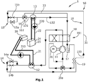
- the refrigerant circuit 10 is shown in a normal heating mode.
- the normal heating mode is intended for normal or non-excessive temperature control of the vehicle interior, especially at ambient temperatures of -5 ° C to + 20 ° C.
- the refrigerant circuit 10 is operated as a heat pump 50 in the known manner.
- the refrigerant 100 is conveyed from the high pressure side of the compressor 11 via the switchover valve 18, which is switched to a first switching position 181, to the condenser 12.
- the condenser 12 the refrigerant 100 can give off heat to the first coolant circuit 21.
- the heat absorbed by the first coolant 210 is conveyed to the interior heat exchanger 26 and can there be given off to an air flow into the vehicle interior.
- the refrigerant 100 cooled via the condenser 12 is conveyed via the check valve 14a of the expansion device 14 to the internal heat exchanger 19, via which the refrigerant 100 can give off further heat to a counterflow of the refrigerant 100. Then, the refrigerant 100 becomes the throttle 15b of FIG Conveyed expansion device 15, which causes a pressure reduction of the refrigerant 100. Downstream of the throttle 15b, the refrigerant 100 reaches the control valve 16, which is switched to a first switching position 161 in order to direct the refrigerant 100 to the evaporator 13. In the evaporator 13, the refrigerant 100 can absorb heat from the second coolant circuit 22.
- the required heat of the second coolant flow 220 can be provided, for example, via the unit heat exchanger 24.
- the refrigerant 100 heated in the evaporator 13 then passes via the switching valve 18 into a collecting container 17 in which the refrigerant 100 can be stored for a certain time.
- the temporarily stored refrigerant 100 can in turn be conveyed out of the collecting container 17 and absorb heat from the refrigerant counterflow via the adjoining internal heat exchanger 19.
- the refrigerant 100 will then be conducted via a valve 20a to the engine heat exchanger 20, via which the refrigerant 100 can absorb further heat.
- the refrigerant 100 is fed back to the high pressure side of the compressor by the compressor 11.
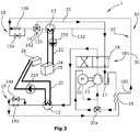
- the refrigerant circuit 10 of the heating / cooling system 1 is shown in an extreme heating mode.
- the extreme heating mode is intended for energy-saving temperature control of the vehicle interior at ambient temperatures of -5 ° C to + 20 ° C or for normal temperature control of the vehicle interior, especially at extremely low ambient temperatures below -5 ° C.
- the refrigerant circuit 10 is operated as a heat pump 50, but the refrigerant 100 is not conveyed through the evaporator 13, but rather through a bypass line 33 to bypass the evaporator 13.
- the control valve 16 is for this purpose switched to a second switching position 162, in which the control valve 16 directs the refrigerant flow 100 into the bypass line 33.
- the refrigerant circuit 10 thus comprises only the compressor 11 and the condenser 12 as heat-exchanging components in the extreme heating mode.
- the heat absorbed in the condenser 12 by the first coolant 210 is conveyed to the interior heat exchanger 26 and can be used there for temperature control an air flow can be released into the vehicle interior.
- the refrigerant 100 is in the in Figure 2
- the extreme heating mode shown is conveyed from the high pressure side of the compressor 11 via the switching valve 18, which is switched to the first switching position 181, to the condenser 12, via which the refrigerant 100 can give off heat to the first coolant circuit 21.
- the heat absorbed by the first coolant 210 is conveyed to the interior heat exchanger 26 and can there be given off to an air flow into the vehicle interior.
- the refrigerant 100 cooled via the condenser 12 is conveyed via the check valve 14a of the expansion device 14 to the internal heat exchanger 19, via which the refrigerant 100 can give off further heat to the counterflow of the refrigerant 100.
- the refrigerant 100 is then conveyed to the throttle 15 b of the expansion device 15, which causes a pressure reduction in the refrigerant 100. Downstream of the throttle 15b, the refrigerant 100 reaches the control valve 16, which is switched to a second switching position 162 in order to guide the refrigerant 100 into the bypass line 33.
- the refrigerant 100 consequently does not flow through the evaporator 13 and thus also does not absorb any heat from the second coolant circuit 22 via the evaporator 13.
- the second coolant circuit 22 can therefore be switched to be inoperative or its own Represent heat pump cycle.
- the second coolant 220 can absorb heat in an aggregate heat exchanger 24 and release it again, for example, to a frozen ambient heat exchanger 25 for defrosting the ambient heat exchanger 25.
- the second coolant circuit 22 is advantageously not in a heat exchange with the refrigerant circuit 10.
- the refrigerant 100 then passes via the switchover valve 18 into the collecting container 17, in which the refrigerant 100 can be stored for a certain time.
- the temporarily stored refrigerant 100 can in turn be conveyed out of the collecting container 17 by the compressor 11 and absorb heat from the refrigerant counterflow via the adjoining internal heat exchanger 19.
- the refrigerant 100 will then be conducted via the branch valve 20a to the engine heat exchanger 20, via which the refrigerant 100 can absorb further heat.
- the heating can take place directly by flowing over the engine heat exchanger 20.
- the motor M of the compressor 11 is thereby cooled.
- the refrigerant 100 is fed back to the high pressure side of the compressor by the compressor 11.
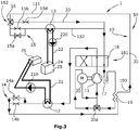
- FIG. 3 an alternative embodiment of the refrigerant circuit 10 of the heating / cooling system 1 is shown in the extreme heating mode.
- the bypass line 33 branches off from the main line 30 in the flow direction upstream of the expansion device 15.
- the control valve 16, which is switched to the second switching position 162 is arranged at the junction, so that the refrigerant flow 100 is directed into the bypass line 33.
- a throttle 15d is arranged within the bypass line 33. This results in a pressure reduction of the refrigerant 100 in the bypass line 33.
- the thermal interaction or the heat conduction in the refrigerant circuit 10 this configuration corresponds to the thermal interaction of the Figure 2 refrigerant circuit 10 shown.
- the refrigerant circuit 10 is shown in a cooling mode.
- the cooling mode is intended for normal temperature control of the vehicle interior, especially at ambient temperatures between + 20 ° C and + 30 ° C.
- the refrigerant circuit 10 is operated as a refrigeration system 60.
- the refrigerant 100 is conducted from the high pressure side of the compressor 11 via the switchover valve 18, which is switched to a second switching position 182 and causes a flow reversal, to the evaporator 13, which functions as a condenser in cooling mode.
- the refrigerant 100 emits heat via the evaporator 13 to the second coolant circuit 22.
- the heat absorbed by the second coolant 220 is conveyed to the ambient heat exchanger 25 and can there be given off to the environment.
- the refrigerant 100 cooled by the evaporator 13 is conveyed via the control valve 16, which is switched to the first switching position 161, and a check valve 15a of the expansion device 15 to the internal heat exchanger 19, in which the refrigerant 100 transfers further heat to the counterflow of the refrigerant 100 can deliver.
- the refrigerant 100 is then conveyed to a throttle 14b of the expansion device 14, which reduces the pressure of the refrigerant 100. Downstream of the throttle 14b, the refrigerant 100 reaches the condenser 12, which functions as an evaporator. In the condenser 12, the refrigerant 100 absorbs heat from the first coolant circuit 21.
- the first coolant circuit 21 can consequently provide heat for cooling the vehicle interior in the interior heat exchanger 26 take up and release in the condenser 12 to the refrigerant flow 100 again.
- the heated refrigerant 100 then passes via the switching valve 18 into the collecting container 17, in which the refrigerant 100 can be stored for a certain time.
- the refrigerant 100 conveyed from the collecting container 17 can absorb heat from the refrigerant countercurrent via the adjoining internal heat exchanger 19.
- the valve 20a is now switched in such a way that the refrigerant flow 100 is not directed to the engine heat exchanger 20, but rather directly to the compressor 11.
- the refrigerant flow 100 can be routed again via the engine heat exchanger 20.
- the refrigerant 100 is fed back to the high pressure side of the compressor by the compressor 11.
- the refrigerant circuit 10 is in a heat exchange via the condenser 12 with the first coolant circuit 21 and via the evaporator 13 with the second coolant circuit 22.
- the condenser 12 and the evaporator 13 can be flowed through by the coolant 210, 220, 230.
- the refrigerant circuit 10 can - as shown here - be provided without a circuit reversal or with a circuit reversal.
- the bypass line 33 branches off from the main line 30 upstream of the check valve 15a, so that a check valve 15c and a throttle 15d are additionally arranged in the bypass line 33 for pressure regulation.
- the first coolant circuit 21 is connected to the second coolant circuit 22 via a branch or connection 35, so that the first coolant circuit 21 and the second coolant circuit 22 in the FIG Figure 5
- the embodiment shown are interconnected to form an overall coolant circuit 23.
- the circuit is intended for pure heating operation, but can also be used for cooling operation.
- the overall coolant circuit 23 has a coolant pump 211, which enables the coolant 210, 220, 230 to circulate.
- a first shut-off valve 231, a second shut-off valve 232 and a third shut-off valve 233 are provided to guide the coolant flow 210, 220, 230 in the coolant circuit 21, 22, 23.
- the coolant circuit 21, 22, 23 has an interior heat exchanger 26, an ambient heat exchanger 25 and an aggregate heat exchanger 24, via which the coolant 210, 220, 230 can absorb and / or release heat.
- the first shut-off valve 231 and the third shut-off valve 233 are in an open position in which a flow is possible, and the second shut-off valve 232 is in a shut-off position, in which a flow is prevented.
- the coolant 210, 220, 230 conveyed by the coolant pump 211 flows from the pump 211 to the unit heat exchanger 24, in which the coolant 210, 220, 230 can absorb heat from an unit.
- the unit can be a vehicle unit, for example a battery.
- the unit is an additional heater, such as a PTC heater.
- the heated coolant 210, 220, 230 then passes through the evaporator 13, in which the coolant 210, 220, 230 can give off heat to the coolant 100, further through the open-switched first Shut-off valve 231 to the condenser 12.
- the coolant 210, 220, 230 absorbs heat from the coolant 100.
- the heated coolant 210, 220, 230 is conveyed directly to the interior heat exchanger 26, in which the coolant 210, 220, 230 emits heat for heating a vehicle interior (not shown).
- the cooled coolant 210, 220, 230 flows through the open-switched third shut-off valve 233 in turn to the pump 211.
- the heat pump function of the refrigerant circuit 10 increases the amount of the coolant 210, 220, 230 supplied thermal power.
- the coolant 210, 220, 230 for example, a heat output of 1 kW supplied in the unit heat exchanger 24 results in a total heat output of 3 kW due to the amplification by the heat pump function.
- the coolant 210, 220, 230 in the interior heat exchanger 26 only partially emits heat and flows partially heated out of the interior heat exchanger 26. This also results in a self-reinforcing effect in the heat exchange with the refrigerant circuit 10, that is to say the temperature of the coolant 210, 220, 230 increases with the number of passes through the evaporator 13 and the condenser 12.
- the coolant 210, 220, 230 which is heated in the unit heat exchanger 24, which - as explained above - can also be designed as an additional heater, also absorbs further heat in the adjoining condenser 12.
- the coolant 210, 220, 230 heated in this way reaches the interior heat exchanger 26, in which the coolant 210, 220, 230 can give off a great deal of heat for heating a vehicle interior (not shown).
- the third shut-off valve 233 is switched to a blocking position.
- the coolant 210, 220, 230 is conveyed from the interior heat exchanger 26, in which the coolant 210, 220, 230 only partially emits heat, into the ambient heat exchanger 25.
- the coolant 210, 220, 230 flowing out of the interior heat exchanger 26 therefore still has a temperature that is sufficiently high to defrost the ambient heat exchanger 25 when it flows into the ambient heat exchanger 25.
- the still warm coolant 210, 220, 230 can give off heat to the frozen ambient heat exchanger 25, so that the ambient heat exchanger 25 can be defrosted.
- the first shut-off valve 231 is in a shut-off position
- the second shut-off valve 232 and the third shut-off valve 233 are in an open position.
- the coolant 210, 220, 230 flows from the pump 211 to the unit heat exchanger 24, in which the coolant 210, 220, 230 can absorb heat from an unit.
- the heated coolant 210, 220, 230 then passes through the evaporator 13, in which the coolant 210, 220, 230 gives off heat to the coolant 100.
- the cooled coolant 210, 220, 230 is then conveyed through the open second shut-off valve 232 to the interior heat exchanger 26, in which the coolant 210, 220, 230 can absorb heat for cooling a vehicle interior (not shown).
- the coolant 210, 220, 230 reaches the pump 211 again from the interior heat exchanger 26 via the shut-off valve 233.
Landscapes
- Physics & Mathematics (AREA)
- Thermal Sciences (AREA)
- Engineering & Computer Science (AREA)
- Mechanical Engineering (AREA)
- Air-Conditioning For Vehicles (AREA)
Description
- Die Erfindung betrifft ein Heiz-/Kühlsystem für Fahrzeuge vom Wärmepumpentyp sowie ein Verfahren zum Betreiben eines solchen Heiz-/Kühlsystems.
- Derartige Heiz-/Kühlsysteme sind in verschiedenen Ausführungen bekannt, wobei ein Kältemittelkreis als Wärmepumpe und/oder als Kältemaschine betrieben werden kann. Hierzu umfasst der Kältemittelkreis zumindest einen Kompressor, einen Verflüssiger, einen Verdampfer und eine Expansionseinrichtung. Der wesentliche Vorteil eines solchen Heiz-/Kühlsystems liegt in der Möglichkeit einer Verschaltung und Nutzbarmachung der einzelnen Wärmequellen und Wärmesenken eines Fahrzeugs zum Beheizen oder zum Kühlen des Fahrzeuginnenraums.
- In Fahrzeugen der neuesten Generation, insbesondere Fahrzeuge mit einem reinen Elektroantrieb oder einem Hybridantrieb, stehen solche Wärmequellen und Wärmesenken jedoch nicht oder nur in geringem Maße für eine Temperierung des Fahrzeuginnenraums zur Verfügung. Dieser bauartbedingte Nachteil kann durch Umgebungseinflüsse weiter verstärkt werden, beispielsweise wenn ein Teil des Heiz-/Kühlsystems aufgrund extrem niedriger Außentemperaturen eingefroren ist und somit dem Heiz-/Kühlsystem nicht zur Verfügung steht. Darüber hinaus ist es bei solchen Fahrzeugen erforderlich, dass nicht nur der Fahrzeuginnenraum, sondern auch verschiedene Fahrzeugaggregate zum Einhalten eines bestimmten Temperaturbereichs beheizt oder gekühlt werden.
- Bekannte Heiz-/Kühlsysteme stoßen daher bei Elektro- oder Hybridfahrzeugen, insbesondere bei extrem hohen oder extrem niedrigen Temperaturen, schnell an ihre Grenzen.
- Die
DE 44 10 057 C2 beschreibt einen Wärmepumpen-Kreislauf, bei dem ein Kältemittel in einem Verdampfer Wärme von einem Luftstrom aufnehmen und in einem Verflüssiger Wärme an einen Luftstrom abgeben kann. Der Wärmepumpen-Kreislauf weist einen Bypass um den Verflüssiger auf, so dass bei sehr niedrigen Außentemperaturen zum Abtauen eines eingefrorenen Verdampfers das Kältemittel als Heißgas von einem Kompressor direkt in den Verdampfer geleitet werden kann. Der Verflüssiger wird hierbei durch den Bypass vollständig überbrückt. - Die
WO 2012 075 975 A1 beschreibt eine Heiz-/Kühleinrichtung mit einem Kältemittel-Kreislauf, der über einen Verflüssiger und über einen Verdampfer jeweils mit einem separat ausgebildeten Kühlmittelkreislauf in einem Wärmeaustausch steht. Die Kühlmittelkreisläufe wirken mit weiteren Wärmetauschern des Fahrzeugs zusammen und können für eine optimale Verschaltung der Wärmequellen und Wärmesenken eines Fahrzeuges miteinander verbunden werden. - Die
WO 2012 / 084 175 A1 beschreibt eine Klimaanlage für Elektrofahrzeuge mit einem Kältemittelkreis, der zwei luftüberströmte Wärmetauscher aufweist und über einen dritten Wärmetauscher mit einem separaten Fluidkreis koppelbar ist. Der Fluidkreis steht mit einer Wärmequelle des Fahrzeugs, insbesondere einer Batterie, in einem Wärmeaustausch und weist eine Zusatzheizung auf. - Die
EP 2 110 274 A1 beschreibt eine Heiz-/Kühleinrichtung für Fahrzeuge mit einem Wärmepumpenkreislauf, bei dem das Kältemittel sowohl in einem Heizbetrieb als auch in einem Kühlbetrieb den Wärmepumpenkreislauf in derselben Richtung durchströmt. Dazu sind neben den an sich bekannten Komponenten eines Wärmepumpenkreislaufs zusätzlich ein innerer Wärmetauscher sowie verschiedene Umgebungsleitungen vorgesehen. - Die
EP 1 348 920 A2 beschreibt eine Wärmepumpe zum gleichzeitigen Kühlen und Heizen von Fahrzeugen mit einem Kältemittel-Kreislauf, bei dem drei Wärmetauscher vorgesehen sind, die jeweils als Verflüssiger oder Verdampfer betrieben werden können. Jeder Wärmetauscher weist eine Bypass-Leitung auf, so dass das Kältemittel beispielsweise durch einen ersten oder alternativ durch einen zweiten als Verdampfer wirkenden Wärmetauscher geleitet werden kann. - Die
US 2011/0284181 A1 zeigt einen als Wärmepumpe ausgebildeten Kältemittelkreislauf, bei dem die Strömungsrichtung des Kältemittels mittels eines Umschaltventils geändert werden kann. In einer Ausgestaltung kann das Kältemittel wahlweise durch einen ersten oder einen zweiten als Verdampfer wirkenden Wärmetauscher geleitet werden. - Nachteilig an den vorgenannten Systemen ist, dass in einem Abtaubetrieb, beispielsweise zum Abtauen des Verdampfers, an dem Verflüssiger des Kältemittelkreises Wärme, zum Beispiel für die Beheizung eines Fahrzeuginnenraums, nicht bereitgestellt werden kann. Daher ist bei solchen Systemen eine Zusatzheizung erforderlich, die jedoch einen erhöhten Energieverbrauch und dadurch eine geringere Reichweite des Fahrzeugs verursacht.
- Aufgabe der vorliegenden Erfindung ist es daher, ein Heiz-/Kühlsystem bereitzustellen, das in Fahrzeugen mit einem Elektromotor und/oder Verbrennungsmotor auch bei extremen Temperaturen eine effiziente und rasche Temperierung des Fahrzeuginnenraums sowie der Fahrzeugaggregate ohne eine separate Zusatzheizung bzw. Zusatzkühlung ermöglicht. Ferner soll ein Verfahren bereitgestellt werden, mit dem ein solches Heiz-/Kühlsystem betrieben werden kann. Die Lösung der Aufgabe erfolgt erfindungsgemäß durch ein Heiz-/Kühlsystem mit den Merkmalen des Anspruchs 1 sowie durch ein Verfahren mit den Merkmalen des Anspruchs 11.
- In bekannter Weise umfasst das Heiz-/Kühlsystem für ein Kraftfahrzeug einen Kältemittel-Kreislauf, insbesondere einen als Wärmepumpe und/oder Kältemaschine ausgebildeten Kältemittel-Kreislauf. Der Kältemittel-Kreislauf besteht vorzugsweise aus einer Hauptleitung, die von einem Kältemittel durchströmbar ist und die folgenden Komponenten eines Kältemittel-Kreislaufs miteinander verbindet: zumindest einen Kompressor, einen Verflüssiger bzw. Gaskühler, einen Verdampfer und eine Expansionseinrichtung bzw. ein Expansionsventil. Der Verflüssiger ist mit einem ersten Kühlmittel-Kreislauf und der Verdampfer mit einem zweiten Kühlmittel-Kreislauf koppelbar, so dass das Kältemittel des Kältemittel-Kreislaufs in dem Verflüssiger mit einem ersten Kühlmittel-Kreislauf und in dem Verdampfer mit einem zweiten Kühlmittel-Kreislauf in einem Wärmeaustausch stehen kann. Durch die Anordnung der Kühlmittel-Kreisläufe ist eine Erweiterung bzw. Ausdehnung des Heiz-/Kühlsystems auf sämtliche, auch weit voneinander entfernt liegende Wärmequellen und Wärmesenken eines Fahrzeugs ermöglicht. Dies ist insbesondere gegenüber Kältemittel-Kreisläufen mit luftüberströmten Wärmetauschern vorteilhaft. Somit können sämtliche in einem Fahrzeug angeordnete Wärmequellen und Wärmesenken in das Heiz-/Kühlsystem integriert bzw. thermisch miteinander vernetzt werden. Die einzelnen Kühlmittel-Kreisläufe können separat und/oder untereinander verbindbar ausgebildet sein, so dass sich weitere Verschaltungsmöglichkeiten ergeben. Ferner ermöglicht diese Anordnung, dass je nach Bedarf das Kältemittel entweder von einem ersten Kühlmittel-Kreislauf erwärmt und von dem zweiten Kühlmittel-Kreislauf gekühlt wird oder von beiden Kühlmittel-Kreisläufen gleichzeitig erwärmt bzw. gekühlt wird. Somit ist eine intensive und rasche Erwärmung bzw. Kühlung des Kältemittels möglich. Darüber hinaus ist vor dem Hintergrund der hohen Preise für Kältemittel ein weiterer Vorteil, dass die Kältemittelmenge relativ gering gehalten werden kann. Ferner kann die Anzahl der Problemstellen eines Kältemittel-Kreislaufs minimiert werden, insbesondere kann die Anzahl möglicher Leckagestellen verringert und Hochdruckbereiche verkleinert werden. Ferner weist der Kältemittel-Kreislauf einen inneren Kältemittel-Wärmetauscher auf, der beidseitig mit dem Kältemittel des Kältemittel-Kreislaufs gekoppelt ist. Der innere Kältemittel-Wärmetauscher ist in dem Kältemittel-Kreislauf hochdruckseitig bevorzugt zwischen dem Verflüssiger und dem Verdampfer und niederdruckseitig zwischen einem Sammelbehälter und dem Kompressor angeordnet. Dadurch kann der Kältemittel-Kreislauf zusätzlich in eine selbstverstärkende Verschaltung gebracht werden, in der das Kältemittel in einem bestimmten Bereich des Kältemittel-Kreislaufs, nämlich im Wärmepumpenbetrieb stromabwärts des Verflüssigers und im Kälteanlagenbetrieb stromabwärts des Verdampfers, Wärme an das Kältemittel in einem anderen Bereich des Kältemittel-Kreislaufs übertragen kann, nämlich im Wärmepumpenbetrieb an das Kältemittel stromabwärts des Verdampfers und im Kälteanlagenbetrieb stromabwärts des Verflüssigers.
- Erfindungsgemäß weist der Kältemittel-Kreislauf ein Umschaltventil, insbesondere ein Vier-Wege-Ventil, zur Umkehrung der Strömungsrichtung in dem Kältemittel-Kreislauf auf. Das Umschaltventil weist vorzugsweise zwei Eingänge und zwei Ausgänge auf. Dadurch kann das Umschaltventil zum Einen den Kältemittelstrom stromabwärts des Kompressors entweder in einem Wärmepumpenbetrieb, insbesondere Extrem-Heizbetrieb, zu dem Verflüssiger oder alternativ in einem Kälteanlagenbetrieb zu dem Verdampfer leiten und zum Anderen entweder in einem Wärmepumpenbetrieb den Kältemittelstrom stromabwärts des Verdampfers bzw. stromabwärts der Umgehungsleitung zu einem Sammelbehälter oder in einem Kälteanlagenbetrieb den Kältemittelstrom stromaufwärts des Verdampfers zu einem Sammelbehälter leiten. Dadurch ist der Kältemittel-Kreislauf zu einer Wärmepumpe oder zu einer Kälteanlage schaltbar. In einem Wärmepumpenbetrieb nimmt das Kältemittel in dem Verdampfer Wärme von dem zweiten Kühlmittel-Kreislauf auf und gibt in dem Verflüssiger Wärme an den ersten Kühlmittel-Kreislauf ab. In einem Kühlbetrieb sind die Strömungsrichtung des Kältemittels in dem Kältemittel-Kreislauf sowie die Funktionsweise der Wärmetauscher, insbesondere des Verflüssigers und des Verdampfers, umgekehrt. So wird der Verdampfer als ein Verflüssiger und der Verflüssiger als ein Verdampfer betrieben. Dadurch nimmt das Kältemittel in dem ehemals als Verflüssiger und nun als Verdampfer wirkenden Wärmetauscher Wärme von dem ersten Kühlmittel-Kreislauf auf und gibt in dem ehemals als Verdampfer und nun als Verflüssiger betriebenen Wärmetauscher Wärme an den zweiten Kühlmittel-Kreislauf ab.
- Ferner ist erfindungsgemäß der Verdampfer des Kältemittel-Kreislaufs von dem Kältemittel umgehbar. Dadurch kann der Verdampfer in dem Kältemittel-Kreislauf vollständig überbrückt werden und folglich die Wärmeübertragung in dem Verdampfer funktionslos geschaltet werden.
- Diese Anordnung hat den Vorteil, dass bei sehr niedrigen Außentemperaturen, insbesondere Temperaturen niedriger als -5 °C, der Kältemittelstrom des Kältemittel-Kreislaufs in eine "Kurzkreis-Schaltung" gebracht werden kann, in der das Kältemittel fortwährend den Kompressor und den Verflüssiger durchströmt, nicht aber den Verdampfer. Dadurch erfolgt in dem Verdampfer keine Wärmeübertragung von dem Kühlmittel zumindest des zweiten Kühlmittel-Kreislauf auf das Kältemittel oder umgekehrt. Vorzugsweise kann das Kältemittel in dem Kompressor stetig Wärme aufnehmen, insbesondere von dem elektrischen Antrieb des Kompressors. Die von dem Kältemittel aufgenommene Wärme kann in dem Verflüssiger an den ersten Kühlmittel-Kreislauf abgegeben werden. Das Kühlmittel des ersten Kühlmittel-Kreislaufs kann somit bis zu einer bestimmten Höchsttemperatur erwärmt werden. Das abgekühlte Kältemittel wird wiederum direkt zu dem Kompressor geleitet, in dem das Kältemittel wieder erwärmt wird. Durch diese "Kurzkreis-Schaltung" kann eine ausreichend hohe Temperatur beispielsweise zur (Vor-)Beheizung des Fahrzeuginnenraums oder eines Fahrzeugaggregats bereitgestellt werden, unabhängig von dem zweiten Kühlmittelstrom.
- Ein weiterer Vorteil ist die Möglichkeit einer vollständigen Abkopplung des zweiten Kühlmittel-Kreislaufs von dem Kältemittel-Kreislauf. Dabei kann der zweite Kühlmittel-Kreislauf bei sehr niedrigen Außentemperaturen vollständig funktionslos geschaltet werden. Dies ist besonders vorteilhaft, wenn der zweite Kühlmittel-Kreislauf mit einem Wärmetauscher in Verbindung steht, der aufgrund der sehr niedrigen Temperaturen nicht funktionsfähig bzw. eingefroren ist. Beispielsweise kann das Kühlmittel des zweiten Kühlmittel-Kreislaufs in einem Aggregat-Wärmetauscher, beispielsweise einer Batterie, Wärme aufnehmen und in einem vereisten Umgebungs-Wärmetauscher abgeben. Dadurch kann der zweite Kühlmittel-Kreislauf als ein eigenständiger bzw. separat ausgebildeter Heiz-Kreislauf betrieben werden. Ferner kann der Kältemittel-Kreislauf zur Energieeinsparung durch die Abkopplung des zweiten Kühlmittel-Kreislaufs bei Bedarf von dem Kältemittel-Kreislauf vollständig funktionslos geschaltet werden.
- Vorzugsweise weist der Kältemittel-Kreislauf eine Umgehungsleitung zur Umgehung des Verdampfers auf. Dadurch kann der Verdampfer und ein Teil der Hauptleitung des Kältemittel-Kreislaufs überbrückt werden. Das Kältemittel des Kältemittel-Kreislaufs kann hierbei an dem Verdampfer und dem Teil der Hauptleitung parallel vorbei geleitet werden. Die Umgehungsleitung kann zwischen einer zu dem Verdampfer hin führenden Leitung und einer von dem Verdampfer weg führenden Leitung angeordnet sein, insbesondere zweigt die Umgehungsleitung an einer Zuströmseite des Verdampfers von der Hauptleitung ab und mündet an einer Abströmseite des Verdampfers in die Hauptleitung. Folglich kann der Kältemittelstrom stromaufwärts des Verdampfers von der Hauptleitung in die Umgehungsleitung abgezweigt und stromabwärts des Verdampfers wieder in die Hauptleitung geleitet werden, ohne den Verdampfer zu durchströmen.
- Der Kältemittel-Kreislauf kann ein Steuerventil zum selektiven Lenken des Kältemittelstroms zu der Umgehungsleitung und/oder zu dem Verdampfer aufweisen. Das Steuerventil kann innerhalb der Umgehungsleitung und/oder in der Eingangsleitung des Verdampfers und/oder Ausgangsleitung des Verdampfers angeordnet sein. Bevorzugt ist das Steuerventil in der stromaufwärts des Verdampfers befindlichen Eingangsleitung des Verdampfers angeordnet. Das Steuerventil ist als ein Abzweigventil mit einer Sperrfunktion ausgebildet, beispielsweise ein Drei-Zwei-Wege-Ventil oder eine Kombination aus zwei Zwei-WegeVentilen. Es bleibt dabei dem Fachmann überlassen, durch Kombination verschiedener Ventile den Kältemittelstrom entweder durch den Verdampfer oder durch die Umgehungsleitung zu leiten. Das Steuerventil kann auch geeignet sein, den Kältemittelstrom zu einem Teil in die Umgehungsleitung und zu einem anderen Teil in den Verdampfer zu leiten. Dadurch kann die "Kurzkreis-Schaltung" des Kältemittelstroms je nach Bedarf stufenlos zugeschaltet werden.
- In einer vorteilhaften Ausgestaltung weist der Kältemittel-Kreislauf einen Motor-Wärmetauscher auf, insbesondere einen Wärmetauscher des Kompressormotors. Der Motor-Wärmetauscher kann hochdruckseitig oder niederdruckseitig angeordnet sein, vorzugsweise befindet sich der Motor-Wärmetauscher niederdruckseitig innerhalb des Kompressorgehäuses unmittelbar an dem Kompressormotor. Dadurch kann die an dem Motor des Kompressors, insbesondere einem Elektromotor, entstehende Abwärme unmittelbar an den Kältemittelstrom abgegeben werden, sobald der Kompressor eingeschaltet ist, das heißt sobald der Kältemittel-Kreislauf aktiviert ist. Dadurch ist eine dauerhafte Wärmeübertragung von dem Kompressormotor zu dem Kältemittel möglich. Eine zusätzliche Beheizung des Kältemittels ist nicht erforderlich. Das Kältemittel kann dadurch auch bei extrem niedrigen Außentemperaturen und einer daraus resultierenden nicht effektiven Wärmeübertragung an dem Verdampfer ausreichend erwärmt werden. Gleichzeitig wird der Kompressormotor auf diese Weise gekühlt. Alternativ kann der elektromotorisch angetriebene Kompressor in bekannter Art und Weise saugdampfgekühlt ausgeführt sein.
- Vorzugsweise weist der Kältemittel-Kreislauf eine Drossel auf, die stufenlos verstellbar ist. Die Drossel ist bevorzugt in der Hauptleitung stromaufwärts des Verdampfers vor der Abzweigung in die Umgehungsleitung angeordnet, insbesondere kann die Drossel zwischen einem inneren Wärmetauscher des Kältemittel-Kreislaufs und einem Abzweigventil der Umgehungsleitung angeordnet sein. Der Motor-Wärmetauscher kann auch der Elektromotor des Kompressors selbst sein. Vorzugsweise ist eine einzige Drossel der Umgehungsleitung des Verdampfers wie auch dem Verdampfer selbst zuordenbar, wodurch sowohl eine Regelung der Betriebsdrücke im Kühlbetrieb als auch im Extrem-Heizbetrieb realisiert wird (z. B. Hochdruck, Niederdruck im Bypassbetrieb). Alternativ kann eine weitere Drossel auch innerhalb der Umgehungsleitung angeordnet sein. Dadurch kann der in der Umgehungsleitung vorherrschende Druck des Kältemittels mittels der Drossel eigenständig stufenlos eingestellt werden. Die Drossel kann in Bezug auf Drosselquerschnitt und/oder Öffnungszeit variabel ausgebildet sein. Dadurch sind die Betriebsdrücke durch Variation des Öffnungsquerschnitts der Drossel bzw. Öffnungszeit der Drossel derart einstellbar, dass die größtmögliche Effizienz des Kältemittelkreises in allen Betriebszuständen sichergestellt ist.
- An einer Eingangsseite des inneren Kältemittel-Wärmetauschers und an einer Ausgangsseite des inneren Kältemittel-Wärmetauschers ist vorzugsweise jeweils ein Temperatursensor zur Messung der Temperatur des in den bzw. aus dem inneren Kältemittel-Wärmetauscher strömenden Kältemittels angeordnet. Dadurch kann eine Temperaturdifferenz zwischen dem in den Kältemittel-Wärmetauscher einströmenden und dem aus dem Kältemittel-Wärmetauscher ausströmenden Kältemittel erfasst werden. Die Temperaturdifferenz kann für die Regelung des Kompressors und/oder des Steuerventils zum Leiten des Kältemittelstroms durch die Umgehungsleitung und/oder durch den Verdampfer genutzt werden. Somit kann insbesondere eine Überhitzung des durch die Umgehungsleitung geleiteten Kältemittels am Eintritt in den Kompressor sichergestellt werden. Alternativ kann eine Regelung der Temperaturdifferenz niederdruckseitig über den inneren Wärmetauscher durch den in den Verflüssiger geleiteten Kühlmittelvolumenstroms des ersten Kühlmittel-Kreislaufs mittels der Kühlmittel-Pumpe des ersten Kühlmittelkreises erfolgen.
- In einer Ausgestaltung weist der Kältemittel-Kreislauf einen Sammelbehälter auf, der als ein Speicher, insbesondere als ein PufferSpeicher, ausgebildet sein kann. Der Sammelbehälter ist vorzugsweise stromabwärts des Verdampfers zwischen einem Umschaltventil und einem inneren Wärmetauscher des Kältemittel-Kreislaufs angeordnet.
- Vorzugsweise weisen der erste Kühlmittel-Kreislauf und/oder der zweite Kühlmittel-Kreislauf jeweils einen Fahrzeug-Innenraum-Wärmetauscher auf. Der Innenraum-Wärmetauscher des ersten und/oder zweiten Kühlmittel-Kreislaufs ist über den Verflüssiger und/oder den Verdampfer mit dem Kältemittel-Kreislauf thermisch koppelbar. Der Innenraum-Wärmetauscher wird vorzugsweise von in den Fahrzeuginnenraum strömender Frischluft überströmt, so dass die überströmende Frischluft mittels eines oder mittels beider Innenraum-Wärmetauscher beheizt oder gekühlt werden kann. Alternativ kann anstatt Frischluft teilweise oder vollständig Luft des Fahrzeuginnenraums durch Rezirkulation (Umluftbetrieb) mittels Innenraumwärmetauscher geheizt oder gekühlt werden, woraus sich eine Reduktion der für die Klimatisierung ergebenden Leistungsaufnahme ergibt. Die Innenraum-Wärmetauscher sind bevorzugt in Reihe geschaltet, so dass ein verstärkender Effekt hinsichtlich der Temperierung möglich ist. Vorzugsweise sind die Innenraum-Wärmetauscher jeweils über eine Zuleitung und eine stufenlos einstellbare Ventileinrichtung mit dem entsprechenden Kühlmittel-Kreislauf koppelbar, so dass der Kühlmittelstrom den Innenraum-Wärmetauscher nur bei Bedarf durchströmt. Bei sehr niedrigen Temperaturen und der erfindungsgemäßen Verschaltung des Kältemittelstroms in die Umgehungsleitung kann der Innenraum-Wärmetauscher allein auf den ersten Kühlmittel-Kreislauf geschaltet sein. Dabei nimmt das Kühlmittel des ersten Kühlmittel-Kreislaufs in dem Verflüssiger des Kältemittel-Kreislaufs und/oder in einem Aggregat-Wärmetauscher Wärme auf, die in dem Innenraum-Wärmetauscher zur Beheizung des Fahrzeuginnenraums abgegeben wird. Sobald der zweite Kühlmittel-Kreislauf, beispielsweise infolge entstehender Abwärme im Fahrbetrieb, zur Wärmeübertragung für eine Beheizung des Fahrzeuginnenraums betriebsbereit ist, kann auch der zweite Kühlmittel-Kreislauf für eine Wärmeübertragung mit dem Heiz-/Kühlmodul thermisch über den Verdampfer kommunizieren und aufgenommene Abwärme über den Verdampfer an das Kältemittel sukzessive abgeben. Die Umgehung des Verdampfers kältemittelseitig kann dabei vollständig oder teilweise geschlossen werden.
- Der erste Kühlmittel-Kreislauf und/oder der zweite Kühlmittel-Kreislauf können zumindest einen Aggregat-Wärmetauscher aufweisen. Der Aggregat-Wärmetauscher des ersten und/oder zweiten Kühlmittel-Kreislaufs ist über den Verflüssiger und/oder den Verdampfer mit dem Kältemittel-Kreislauf thermisch koppelbar. Unter einem Aggregat-Wärmetauscher ist ein Wärmetauscher eines jeden Fahrzeugaggregats, beispielsweise eines Verbrennungsmotors, eines Elektromotors, eines Generators, einer Batterie oder einer Bremsanlage des Fahrzeuges, zu verstehen. Ein Aggregat kann dabei der Antriebsmotor des Fahrzeuges und/oder ein Motor eines Fahrzeugaggregats sein. Ferner kann das Aggregat eine Zusatzheizung, beispielsweise ein PTC-Heizer sein. Vorzugsweise stehen sämtliche Aggregate eines Fahrzeuges für einen Wärmeaustausch mit dem Heiz-/Kühlsystem in Verbindung. Dadurch kann der jeweilige Kühlmittelstrom über den Aggregat-Wärmetauscher Wärme von dem Aggregat aufnehmen und/oder an das Aggregat abgeben. Vorzugsweise ist der Aggregat-Wärmetauscher über eine Zuleitung und eine stufenlos einstellbare Ventileinrichtung mit dem Kühlmittel-Kreislauf koppelbar, so dass der Kühlmittelstrom nur bei Bedarf in den jeweiligen Aggregat-Wärmetauscher geleitet wird. Dadurch kann das Aggregat mittels des jeweiligen Kühlmittel-Kreislaufs auch temporär gekühlt oder beheizt werden, so dass das jeweilige Aggregat in einen optimalen Betriebstemperaturbereich gehalten werden kann. Für eine Kühlung beispielsweise der Batterie nimmt vorzugsweise das Kühlmittel des zweiten Kühlmittel-Kreislaufs beim Durchströmen des Batterie-Wärmetauschers von der Batterie Wärme auf und gibt die Wärme in dem Verdampfer an den Kältemittel-Kreislauf ab. Der Kältemittel-Kreislauf ist hierbei zu dem Verdampfer geleitet, so dass der Kältemittel-Kreislauf Wärme von dem zweiten Kühlmittel-Kreislauf aufnehmen kann. Alternativ kann für eine Erwärmung des Fahrzeuginnenraums der Kältemittelstrom durch die Kältemittel-Umgehungsleitung geleitet sein, so dass der Verdampfer von dem Kältemittel nicht durchströmt wird. In dieser Schaltung steht der zweite Kühlmittel-Kreislauf mit dem Kältemittel-Kreislauf nicht in einem Wärmeaustausch und wird daher von dem Kältemittel-Kreislauf auch nicht gekühlt. Das von einem Aggregat, beispielsweise einer Batterie erwärmte Kühlmittel des zweiten Kühlmittel-Kreislaufs kann bei sehr niedrigen Temperaturen Wärme für eine Enteisung eines Umgebungs-Wärmetauschers bereitstellen. Der Kältemittel-Kreislauf kann dabei funktionslos geschaltet sein oder im Extrem-Heizbetrieb unter kältemittelseitiger Umgehung des Verdampfers betrieben werden.
- Vorzugsweise weisen der erste Kühlmittel-Kreislauf und/oder der zweite Kühlmittel-Kreislauf einen Umgebungs-Wärmetauscher auf. Der Umgebungs-Wärmetauscher des ersten und/oder zweiten Kühlmittel-Kreislaufs ist über den Verflüssiger und/oder den Verdampfer mit dem Kältemittel-Kreislauf thermisch koppelbar. Der Umgebungs-Wärmetauscher kann als ein bekannter Frontend-Wärmetauscher eines Fahrzeuges ausgebildet sein, so dass der jeweilige Kühlmittel-Kreislauf in vorteilhafter Weise Wärme an die Umgebung abgeben oder von der Umgebung aufnehmen kann. Zusätzlich kann der Kühlmittel-Kreislauf eine separat ausgebildete Kühlungseinrichtung aufweisen, beispielsweise einen Ventilator. Vorzugsweise ist die Kühlungseinrichtung ebenfalls an einem Frontend des Fahrzeugs angeordnet. Dadurch kann das Kühlmittel zur Kühlung des Motors Wärme von dem Motor aufnehmen und in dem Umgebungs-Wärmetauscher an die Umgebung oder über den Innenraum-Wärmetauscher an den Innenraum abgeben. Vorzugsweise ist der Umgebungs-Wärmetauscher über eine Zuleitung und eine stufenlos einstellbare Ventileinrichtung mit dem Kühlmittel-Kreislauf koppelbar, so dass der Kühlmittelstrom nur bei Bedarf in den Umgebungs-Wärmetauscher geleitet wird. In einer weiteren bevorzugten Ausführung ist die Kühlungseinrichtung leistungsregelbar.
- In einer Ausgestaltung sind der erste Kühlmittel-Kreislauf und der zweite Kühlmittel-Kreislauf zu einem Gesamt-Kühlmittel-Kreislauf verschaltet. Dadurch kann eine optimale Verschaltung der Wärmequellen und Wärmesenken eines Fahrzeugs erfolgen. Ferner ist für den Kühlmittelstrom lediglich ein Kühlmittel-Pumpe erforderlich.
- Erfindungsgemäß ist in einem Verfahren zum Betreiben eines Heiz-/Kühlsystems vorgesehen, dass in einem Normal-Heizmodus das Steuerventil in eine erste Schaltposition geschaltet wird, so dass der Kältemittelstrom in der Reihenfolge durch den Kompressor, den Verflüssiger, die Expansionseinrichtung, insbesondere ein Rückschlagventil und eine Drossel, und den Verdampfer befördert wird. In einem Extrem-Heizmodus wird das Steuerventil in eine zweite Schaltposition geschaltet, so dass der Kältemittelstrom in der Reihenfolge durch den Kompressor, den Verflüssiger, die Expansionseinrichtung und die Umgehungsleitung befördert wird, so dass der Kältemittelstrom den Verdampfer umgeht. Der Kältemittelstrom wird insbesondere von der Eingangsseite des Verdampfers zu der Ausgangsseite des Verdampfers befördert, ohne den Verdampfer zu durchströmen. Dabei nimmt der Kältemittelstrom in dem Extrem-Heizmodus vorzugsweise allein von dem Kompressor, insbesondere dem Kompressormotor, Wärme auf und gibt die Wärme über den Verflüssiger an den ersten Kühlmittel-Kreislauf ab. Der zweite Kühlmittel-Kreislauf kann hierbei funktionslos geschaltet sein.
- Erfindungsgemäß ist zusätzlich vorgesehen, dass in einem Normal-Heizmodus ein Umschaltventil in eine erste Schaltposition geschaltet wird, so dass der Kältemittelstrom von dem Kompressor durch das Umschaltventil zu dem Verflüssiger und ein Gegenstrom des Kältemittels von dem Verdampfer durch das Umschaltventil zu dem Kompressor befördert werden. In einem Extrem-Heizmodus wird das Umschaltventil ebenfalls in die erste Schaltposition geschaltet, so dass der Kältemittelstrom hierbei von dem Kompressor durch das Umschaltventil zu dem Verflüssiger und ein Gegenstrom des Kältemittels von der Umgehungsleitung durch das Umschaltventil zu dem Kompressor befördert werden. In einem zusätzlichen Kühlmodus wird das Umschaltventil in eine zweite Schaltposition geschaltet, so dass der Kältemittelstrom in der Reihenfolge durch den Kompressor, das Umschaltventil, den Verdampfer, die Expansionseinrichtung, insbesondere ein Rückschlagventil und eine Drossel, den Verflüssiger und erneut durch das Umschaltventil zu dem Kompressor befördert wird.
- Erfindungsgemäß ist zusätzlich vorgesehen, dass dem Kältemittelkreislauf ein innerer Kältemittel-Wärmetauscher zugeordnet wird. Dadurch kann in dem Kältemittel-Wärmetauscher in dem Normal-Heizmodus der von dem Verflüssiger zu dem Verdampfer strömende . Kältemittelstrom Wärme an den von dem Verdampfer zu dem Kompressor strömenden Kältemittelstrom abgeben, in dem Extrem-Heizmodus der von dem Verflüssiger zu dem Verdampfer strömende Kältemittelstrom Wärme an den von der Umgehungsleitung zu dem Kompressor strömenden Kältemittelstrom abgeben, und in dem Kühlmodus der von dem Verdampfer zu dem Verflüssiger strömenden Kältemittelstrom Wärme an den von dem Verflüssiger zu dem Kompressor strömende Kältemittelstrom abgeben.
- Gemäß einer weiteren vorteilhaften Weiterentwicklung des Verfahrens zum Betreiben eines Heiz-/Kühlsystems ist zusätzlich vorgesehen, dass dem Kältemittelkreislauf ein Sammelbehälter zugeordnet wird, so dass in dem Normal-Heizmodus der von dem Verdampfer zu dem Kompressor strömende Kältemittelstrom in dem Sammelbehälter zwischengespeichert wird, in dem Extrem-Heizmodus der von der Umgehungsleitung zu dem Kompressor strömende Kältemittelstrom in dem Sammelbehälter zwischengespeichert wird, und in dem Kühlmodus der von dem Verflüssiger zu dem Kompressor strömende Kältemittelstrom in dem Sammelbehälter zwischengespeichert wird.
- In den Figuren sind Ausführungsbeispiele des erfindungsgemäßen Heiz-/Kühlsystems dargestellt und nachfolgend beschrieben:
-
Figur 1 zeigt einen Kältemittel-Kreislauf in einem Normal-Heizbetrieb, -
Figur 2 zeigt einen Kältemittel-Kreislauf in einem Extrem-Heizbetrieb, -
Figur 3 zeigt eine alternative Ausgestaltung des Kältemittel-Kreislaufs in dem Extrem-Heizbetrieb, -
Figur 4 zeigt einen Kältemittel-Kreislauf in einem Kühlbetrieb, und -
Figur 5 zeigt eine Ausgestaltung eines Kühlmittel-Kreislaufs. - In den
Figuren 1 bis 4 ist jeweils ein Kältemittel-Kreislauf 10 des Heiz-/Kühlsystems 1 zum Temperieren eines nicht dargestellten Fahrzeuginnenraums und/oder der nicht näher dargestellten Fahrzeugaggregate gezeigt. Unter Temperieren ist dabei ein Beheizen und/oder Kühlen zu verstehen. Die Steuerung bzw. Regelung des Kältemittel-Kreislaufs 10 sowie der Kühlmittel-Kreisläufe 21, 22 erfolgt über ein nicht dargestelltes Steuergerät mit dazugehörigen Sensoren, Aktuatoren und elektrischen Anschlüssen. - Der Kältemittel-Kreislauf 10 ist von einem Kältemittel 100 durchströmbar und umfasst insbesondere einen Kompressor 11, ein Umschaltventil 18 zur Umkehrung der Strömungsrichtung des Kältemittels 100, einen Verflüssiger 12 und einen Verdampfer 13. Der Kompressor 11 weist einen Kompressor-Antriebsmotor M mit einem Motor-Wärmetauscher 20 auf. Über den Motor-Wärmetauscher 20 kann Abwärme des Motors M an den Kältemittelstrom 100 abgegeben werden. Dazu ist der Motor-Wärmetauscher 20 von dem Kältemittel 100 durchströmbar und kann über ein Ventil 20a dem Kältemittel-Kreislauf 10 zugeordnet werden. Zur Druckregulierung des Kältemittel-Kreislaufs 10 sind Expansionseinrichtungen 14, 15 vorgesehen. Die Expansionseinrichtung 14, 15 ist vorliegend als zumindest eine Drossel 14b, 15b, 15d mit einem parallel geschalteten Rückschlagventil 14a, 15a, 15c ausgebildet. Ferner ist ein innerer Kältemittel-Wärmetauscher 19 vorgesehen, der mit einer ersten Durchströmseite stromabwärts des Verflüssigers 12 zwischen den zwei Expansionseinrichtungen 14, 15 und mit einer zweiten Durchströmseite stromabwärts des Verdampfers 13 zwischen einem Sammelbehälter 17 und dem Kompressor 11 in dem Kältemittel-Kreislauf 10 angeordnet ist.
- Ein erster Kühlmittel-Kreislauf 21 ist von einem ersten Kühlmittelstrom 210 durchströmbar und steht über den Verflüssiger 12 mit dem Kältemittel-Kreislauf 10 in einem Wärmeaustausch. Dazu wird der Verflüssiger 12 sowohl von dem Kältemittel 100 als auch von dem Kühlmittel 210 durchströmt. Der erste Kühlmittel-Kreislauf 21 dient zum Temperieren des Fahrzeuginnenraums. Dazu weist der erste Kühlmittel-Kreislauf 21 einen Innenraum-Wärmetauscher 26 auf.
- Ein zweiter Kühlmittel-Kreislauf 22 ist von einem zweiten Kühlmittelstrom 220 durchströmbar und steht über den Verdampfer 13 mit dem Kältemittel-Kreislauf 10 in einem Wärmeaustausch. Dazu wird der Verdampfer 13 sowohl von dem Kältemittel 100 als auch von dem Kühlmittel 220 durchströmt. Der zweite Kühlmittel-Kreislauf 22 dient zum Temperieren zumindest eines Fahrzeugaggregats. Dazu weist der zweite Kühlmittel-Kreislauf 22 zumindest einen Aggregat-Wärmetauscher 24 auf. Zudem ist in dem zweiten Kühlmittel-Kreislauf 22 ein nicht näher dargestellter Umgebungs-Wärmetauscher 25 angeordnet, über den der Kühlmittelstrom 220 Wärme aufnehmen oder abgeben kann..
- In der
Figur 1 ist der Kältemittel-Kreislauf 10 in einem Normal-Heizbetrieb gezeigt. Der Normal-Heizbetrieb ist für eine normale bzw. nicht-übermäßige Temperierung des Fahrzeuginnenraums insbesondere bei Umgebungstemperaturen von -5°C bis +20°C vorgesehen. - In dem Normal-Heizbetrieb wird der Kältemittel-Kreislauf 10 als Wärmepumpe 50 in der bekannten Weise betrieben. Dazu wird das Kältemittel 100 von der Hochdruckseite des Kompressors 11 über das Umschaltventil 18, das in eine erste Schaltposition 181 geschaltet ist, zu dem Verflüssiger 12 befördert. In dem Verflüssiger 12 kann das Kältemittel 100 Wärme an den ersten Kühlmittel-Kreislauf 21 abgeben. Die von dem ersten Kühlmittel 210 aufgenommene Wärme wird zu dem Innenraum-Wärmetauscher 26 befördert und kann dort an eine Luftströmung in den Fahrzeuginnenraum abgegeben werden.
- Das über den Verflüssiger 12 abgekühlte Kältemittel 100 wird über das Rückschlagventil 14a der Expansionseinrichtung 14 zu dem inneren Wärmetauscher 19 befördert, über den das Kältemittel 100 weitere Wärme an einen Gegenstrom des Kältemittels 100 abgeben kann. Anschließend wird das Kältemittel 100 zu der Drossel 15b der Expansionseinrichtung 15 befördert, die eine Druckminderung des Kältemittels 100 bewirkt. Stromabwärts der Drossel 15b gelangt das Kältemittel 100 zu dem Steuerventil 16, das in eine erste Schaltposition 161 geschaltet ist, um das Kältemittel 100 zu dem Verdampfer 13 zu leiten. In dem Verdampfer 13 kann das Kältemittel 100 Wärme von dem zweiten Kühlmittel-Kreislauf 22 aufnehmen. Die benötigte Wärme des zweiten Kühlmittelstroms 220 kann beispielsweise über den Aggregat-Wärmetauscher 24 bereitgestellt werden.
- Das in dem Verdampfer 13 erwärmte Kältemittel 100 gelangt sodann über das Umschaltventil 18 in einen Sammelbehälter 17, in dem das Kältemittel 100 für eine gewisse Zeit gespeichert werden kann. Aus dem Sammelbehälter 17 kann das zwischengespeicherte Kältemittel 100 wiederum heraus gefördert werden und über den sich anschließenden inneren Wärmetauscher 19 Wärme von dem Kältemittel-Gegenstrom aufnehmen. Das Kältemittel 100 wird sodann über ein Ventil 20a zu dem Motor-Wärmetauscher 20 geleitet sein, über den das Kältemittel 100 weitere Wärme aufnehmen kann. Durch den Kompressor 11 wird das Kältemittel 100 wieder der Hochdruckseite des Kompressors zugeführt.
- In der
Figur 2 ist der Kältemittel-Kreislauf 10 des Heiz-/Kühlsystems 1 in einem Extrem-Heizbetrieb gezeigt. Der Extrem-Heizbetrieb ist für eine energiesparende Temperierung des Fahrzeuginnenraums bei Umgebungstemperaturen von -5°C bis +20°C oder für eine normale Temperierung des Fahrzeuginnenraums insbesondere bei extrem niedrigen Umgebungstemperaturen unterhalb -5°C vorgesehen. - In dem Extrem-Heizbetrieb wird der Kältemittel-Kreislauf 10 als Wärmepumpe 50 betrieben, jedoch wird das Kältemittel 100 nicht durch den Verdampfer 13, sondern durch eine Umgehungsleitung 33 zur Umgehung des Verdampfers 13 befördert. Hierzu ist das Steuerventil 16 in eine zweite Schaltposition 162 geschaltet, in der das Steuerventil 16 den Kältemittelstrom 100 in die Umgehungsleitung 33 leitet. Der Kältemittel-Kreislauf 10 umfasst somit in dem Extrem-Heizbetrieb als wärmeaustauschende Komponenten lediglich den Kompressor 11 und den Verflüssiger 12. Die in dem Verflüssiger 12 von dem ersten Kühlmittel 210 aufgenommene Wärme wird zu dem Innenraum-Wärmetauscher 26 befördert und kann dort zur Temperierung an eine Luftströmung in den Fahrzeuginnenraum abgegeben werden.
- Das Kältemittel 100 wird in dem in
Figur 2 gezeigten Extrem-Heizbetrieb von der Hochdruckseite des Kompressors 11 über das Umschaltventil 18, das in die erste Schaltposition 181 geschaltet ist, zu dem Verflüssiger 12 befördert, über den das Kältemittel 100 Wärme an den ersten Kühlmittel-Kreislauf 21 abgeben kann. Die von dem ersten Kühlmittel 210 aufgenommene Wärme wird zu dem Innenraum-Wärmetauscher 26 befördert und kann dort an eine Luftströmung in den Fahrzeuginnenraum abgegeben werden. - Das über den Verflüssiger 12 abgekühlte Kältemittel 100 wird über das Rückschlagventil 14a der Expansionseinrichtung 14 zu dem inneren Wärmetauscher 19 befördert, über den das Kältemittel 100 weitere Wärme an den Gegenstrom des Kältemittels 100 abgeben kann. Anschließend wird das Kältemittel 100 zu der Drossel 15b der Expansionseinrichtung 15 befördert, die eine Druckminderung des Kältemittels 100 bewirkt. Stromabwärts der Drossel 15b gelangt das Kältemittel 100 zu dem Steuerventil 16, das in eine zweite Schaltposition 162 geschaltet ist, um das Kältemittel 100 in die Umgehungsleitung 33 zu leiten. Das Kältemittel 100 durchströmt folglich nicht den Verdampfer 13 und nimmt somit über den Verdampfer 13 auch keine Wärme von dem zweiten Kühlmittel-Kreislauf 22 auf. Der zweite Kühlmittel-Kreislauf 22 kann daher funktionslos geschaltet sein oder einen eigenen Wärmepumpen-Kreislauf darstellen. Im letzteren Fall kann das zweite Kühlmittel 220 in einem Aggregat-Wärmetauscher 24 Wärme aufnehmen und beispielweise an einen eingefrorenen Umgebungs-Wärmetauscher 25 zum Abtauen des Umgebungs-Wärmetauscher 25 wieder abgeben. Der zweite Kühlmittel-Kreislauf 22 steht hierzu mit dem Kältemittel-Kreislauf 10 vorteilhafterweise nicht in einem Wärmeaustausch.
- Das Kältemittel 100 gelangt sodann über das Umschaltventil 18 in den Sammelbehälter 17, in dem das Kältemittel 100 für eine gewisse Zeit gespeichert werden kann. Aus dem Sammelbehälter 17 kann das zwischengespeicherte Kältemittel 100 wiederum von dem Kompressor 11 heraus gefördert werden und über den sich anschließenden inneren Wärmetauscher 19 Wärme von dem Kältemittel-Gegenstrom aufnehmen. Das Kältemittel 100 wird sodann über das Abzweigventil 20a zu dem Motor-Wärmetauscher 20 geleitet sein, über den das Kältemittel 100 weitere Wärme aufnehmen kann. Die Erwärmung kann unmittelbar durch ein Überströmen des Motor-Wärmetauschers 20 erfolgen. Der Motor M des Kompressors 11 wird dabei gekühlt. Durch den Kompressor 11 wird das Kältemittel 100 wieder der Hochdruckseite des Kompressors zugeführt.
- In der
Figur 3 ist eine alternative Ausgestaltung des Kältemittel-Kreislaufs 10 des Heiz-/Kühlsystems 1 in dem Extrem-Heizbetrieb gezeigt. In dieser Ausgestaltung zweigt die Umgehungsleitung 33 in Strömungsrichtung vor der Expansionseinrichtung 15 von der Hauptleitung 30 ab. An der Abzweigung ist das Steuerventil 16 angeordnet, das in die zweite Schaltposition 162 geschaltet ist, so dass der Kältemittelstrom 100 in die Umgehungsleitung 33 geleitet wird. Innerhalb der Umgehungsleitung 33 ist eine Drossel 15d angeordnet. Dadurch erfolgt eine Druckminderung des Kältemittels 100 in der Umgehungsleitung 33. Das thermische Zusammenwirken bzw. die Wärmeleitung in dem Kältemittel-Kreislauf 10 dieser Ausgestaltung entspricht dem thermischen Zusammenwirken des in derFigur 2 gezeigten Kältemittel-Kreislaufs 10. - In der
Figur 4 ist der Kältemittel-Kreislauf 10 in einem Kühlbetrieb gezeigt. Der Kühlbetrieb ist für eine normale Temperierung des Fahrzeuginnenraums insbesondere bei Umgebungstemperaturen zwischen +20°C und +30°C vorgesehen. - In dem Kühlbetrieb wird der Kältemittel-Kreislauf 10 als eine Kälteanlage 60 betrieben. Dazu wird das Kältemittel 100 von der Hochdruckseite des Kompressors 11 über das Umschaltventil 18, das in eine zweite Schaltposition 182 geschaltet ist und eine Strömungsumkehrung bewirkt, zu dem Verdampfer 13 geleitet, der im Kühlbetrieb als Verflüssiger fungiert. Das Kältemittel 100 gibt dabei Wärme über den Verdampfer 13 an den zweiten Kühlmittel-Kreislauf 22 ab. Die von dem zweiten Kühlmittel 220 aufgenommene Wärme wird zu dem Umgebungs-Wärmetauscher 25 befördert und kann dort an die Umgebung abgegeben werden.
- Das über den Verdampfer 13 abgekühlte Kältemittel 100 wird über das Steuerventil 16, das in die erste Schaltposition 161 geschaltet ist, und ein Rückschlagventil 15a der Expansionseinrichtung 15 zu dem inneren Wärmetauscher 19 befördert, in dem das Kältemittel 100 weitere Wärme an den Gegenstrom des Kältemittels 100 abgeben kann. Anschließend wird das Kältemittel 100 zu einer Drossel 14b der Expansionseinrichtung 14 befördert, die eine Druckminderung des Kältemittels 100 bewirkt. Stromabwärts der Drossel 14b gelangt das Kältemittel 100 zum dem Verflüssiger 12, der als ein Verdampfer fungiert. In dem Verflüssiger 12 nimmt das Kältemittel 100 Wärme von dem ersten Kühlmittel-Kreislauf 21 auf. Der erste Kühlmittel-Kreislauf 21 kann folglich für eine Kühlung des Fahrzeuginnenraums in dem Innenraum-Wärmetauscher 26 Wärme aufnehmen und in dem Verflüssiger 12 an den Kältemittelstrom 100 wieder abgeben.
- Das erwärmte Kältemittel 100 gelangt sodann über das Umschaltventil 18 in den Sammelbehälter 17, in dem das Kältemittel 100 für eine gewisse Zeit gespeichert werden kann. Das aus dem Sammelbehälter 17 beförderte Kältemittel 100 kann über den sich anschließenden inneren Wärmetauscher 19 Wärme von dem Kältemittel-Gegenstrom aufnehmen. Das Ventil 20a ist nun derart geschaltet, dass der Kältemittelstrom 100 nicht zu dem Motor-Wärmetauscher 20, sondern direkt zu dem Kompressor 11 geleitet wird. Sobald der Motor-Wärmetauscher 20 eine bestimmte Temperatur übersteigt, kann der Kältemittelstrom 100 wieder über den Motor-Wärmetauscher 20 geleitet werden. Durch den Kompressor 11 wird das Kältemittel 100 wieder der Hochdruckseite des Kompressors zugeführt.
- In der
Figur 5 ist der Kältemittel-Kreislauf 10 mit einer alternativen Ausgestaltung des Kühlmittel-Kreislaufs 21, 22, 23 gezeigt. - Der Kältemittel-Kreislauf 10 steht, wie in den zuvor beschriebenen Ausgestaltungen, über den Verflüssiger 12 mit dem ersten Kühlmittel-Kreislauf 21 und über den Verdampfer 13 mit dem zweiten Kühlmittel-Kreislauf 22 in einem Wärmetausch. Hierzu ist der Verflüssiger 12 und der Verdampfer 13 von dem Kühlmittel 210, 220, 230 durchströmbar. Der Kältemittel-Kreislauf 10 kann - wie vorliegend dargestellt - ohne Kreislaufumkehr oder mit Kreislaufumkehr vorgesehen sein. Die Umgehungsleitung 33 zweigt in dieser Ausgestaltung vor dem Rückschlagventil 15a von der Hauptleitung 30 ab, so dass zur Druckregulierung zusätzlich in der Umgehungsleitung 33 ein Rückschlagventil 15c und eine Drossel 15d angeordnet sind.
- Der erste Kühlmittel-Kreislauf 21 ist über eine Abzweigung bzw. Verbindung 35 mit dem zweiten Kühlmittel-Kreislauf 22 verbunden, so dass der erste Kühlmittel-Kreislauf 21 und der zweite Kühlmittel-Kreislauf 22 in der in
Figur 5 gezeigten Ausgestaltung zu einem Gesamt-Kühlmittel-Kreislauf 23 verschaltet sind. Die Schaltung ist für einen reinen Heizbetrieb vorgesehen, kann jedoch auch für einen Kühlbetrieb eingesetzt werden. - Der Gesamt-Kühlmittel-Kreislauf 23 weist eine Kühlmittel-Pumpe 211 auf, die eine Zirkulation des Kühlmittels 210, 220, 230 ermöglicht. Zum Leiten des Kühlmittelstroms 210, 220, 230 in dem Kühlmittel-Kreislauf 21, 22, 23 sind ein erstes Absperrventil 231, ein zweites Absperrventil 232 und ein drittes Absperrventil 233 vorgesehen. Ferner weist der Kühlmittel-Kreislauf 21, 22, 23 einen Innenraum-Wärmetauscher 26, einen Umgebungs-Wärmetauscher 25 sowie einen Aggregat-Wärmetauscher 24 auf, über die das Kühlmittel 210, 220, 230 Wärme aufnehmen und/oder abgeben kann.
- In einem Normal-Heizbetrieb, in dem das Kältemittel 100 den Verdampfer 13 durchströmt, ist das erste Absperrventil 231 und das dritte Absperrventil 233 in einer Offen-Position, in der ein Durchströmen möglich ist, und das zweite Absperrventil 232 in einer Sperr-Position, in der ein Durchströmen verhindert wird. Dadurch strömt das von der Kühlmittel-Pumpe 211 beförderte Kühlmittel 210, 220, 230 von der Pumpe 211 zu dem Aggregat-Wärmetauscher 24, in dem das Kühlmittel 210, 220, 230 Wärme von einem Aggregat aufnehmen kann. Das Aggregat kann ein Fahrzeugaggregat, beispielsweise eine Batterie sein. Alternativ ist das Aggregat eine Zusatzheizung, wie ein PTC-Heizer. Das erwärmte Kühlmittel 210, 220, 230 gelangt sodann durch den Verdampfer 13, in dem das Kühlmittel 210, 220, 230 Wärme an das Kältemittel 100 abgeben kann, weiter durch das offen-geschaltete erste Absperrventil 231 zu dem Verflüssiger 12. In dem Verflüssiger 12 nimmt das Kühlmittel 210, 220, 230 Wärme von dem Kältemittel 100 auf. Das erwärmte Kühlmittel 210, 220, 230 wird direkt zu dem Innenraum-Wärmetauscher 26 befördert, in dem das Kühlmittel 210, 220, 230 Wärme zur Beheizung eines nicht dargestellten Fahrzeuginnenraums abgibt. Das abgekühlte Kühlmittel 210, 220, 230 strömt durch das offen-geschaltete dritte Absperrventil 233 wiederum zu der Pumpe 211. Bei dieser Schaltung ergibt sich mittels der Wärmepumpenfunktion des Kältemittel-Kreislaufs 10 eine Verstärkung der durch den Aggregat-Wärmetauscher 24 an das Kühlmittel 210, 220, 230 zugeführten Wärmeleistung. So ergibt sich in dem Kühlmittel 210, 220, 230 beispielsweise aus einer in dem Aggregat-Wärmetauscher 24 zugeführte Wärmeleistung von 1kW aufgrund der Verstärkung durch die Wärmepumpenfunktion eine Gesamt-Wärmeleistung von 3kW.
- Alternativ zu der oben beschriebenen Schaltung gibt das Kühlmittel 210, 220, 230 in dem Innenraum-Wärmetausch 26 nur teilweise Wärme ab und strömt teil-erwärmt aus dem Innenraum-Wärmetauscher 26 heraus. Dadurch ergibt sich ebenfalls ein selbstverstärkender Effekt bei dem Wärmetausch mit dem Kältemittel-Kreislauf 10, das heißt die Temperatur des Kühlmittels 210, 220, 230 steigt mit der Anzahl der Durchläufe durch den Verdampfer 13 und den Verflüssiger 12.
- In einem Extrem-Heizbetrieb, in dem das Kältemittel 100 durch die Umgehungsleitung 33 strömt, kann die gleiche Verschaltung der Absperrventile 231, 232, 233 wie oben in dem Normal-Heizbetrieb der in
Figur 5 dargestellten Ausgestaltung geschaltet sein, das heißt das erste Absperrventil 231 und das dritte Absperrventil 233 sind in der Offen-Position, das zweite Absperrventil 232 in der Sperr-Position geschaltet. Dadurch ergibt sich eine gleiche Durchström-Reihenfolge des Kühlmittels 210, 220, 230 wie oben in dem Normal-Heizbetrieb, jedoch gibt das Kühlmittel 210, 220, 230 in dem Verdampfer 13 keine Wärme an den Kältemittelstrom 100 ab. Dadurch nimmt das Kühlmittel 210, 220, 230, das in dem Aggregat-Wärmetauscher 24 erwärmt wird, der - wie oben erläutert - auch als eine Zusatzheizung ausgebildet sein kann, auch in dem sich anschließenden Verflüssiger 12 weiter Wärme auf. Das so erhitzte Kühlmittel 210, 220, 230 gelangt zu dem Innenraum-Wärmetauscher 26, in dem das Kühlmittel 210, 220, 230 sehr viel Wärme zur Beheizung eines nicht dargestellten Fahrzeuginnenraums abgeben kann. - In einem alternativen Extrem-Heizbetrieb, insbesondere zum Abtauen eines eingefrorenen Umgebungs-Wärmetauschers 25, erfolgt die gleiche Verschaltung wie oben in dem Extrem-Heizbetrieb der in
Figur 5 dargestellten Ausgestaltung, jedoch wird das dritte Absperrventil 233 in eine Sperr-Position geschaltet. Hierbei wird das Kühlmittel 210, 220, 230 von dem Innenraum-Wärmetauscher 26, in dem das Kühlmittel 210, 220, 230 nur teilweise Wärme abgibt, in den Umgebungs-Wärmetauschers 25 befördert. Somit weist das aus dem Innenraum-Wärmetauscher 26 ausströmende Kühlmittel 210, 220, 230 bei Einströmen in den Umgebungs-Wärmetauscher 25 immer noch eine zum Abtauen des Umgebungs-Wärmetauschers 25 ausreichend hohe Temperatur auf. Dadurch kann das noch warme Kühlmittel 210, 220, 230 Wärme an den eingefrorenen Umgebungs-Wärmetauscher 25 abgeben, so dass ein Abtauen des Umgebungs-Wärmetauschers 25 möglich ist. - In einem möglichen Kühlbetrieb, in dem das Kältemittel 100 durch den Verdampfer 13 strömt, ist das erste Absperrventil 231 in einer Sperr-Position, das zweite Absperrventil 232 und das dritte Absperrventil 233 in einer Offen-Position. Dadurch strömt das Kühlmittel 210, 220, 230 von der Pumpe 211 zu dem Aggregat-Wärmetauscher 24, in dem das Kühlmittel 210, 220, 230 Wärme von einem Aggregat aufnehmen kann.
- Das erwärmte Kühlmittel 210, 220, 230 gelangt sodann durch den Verdampfer 13, in dem das Kühlmittel 210, 220, 230 Wärme an das Kältemittel 100 abgibt. Das abgekühlte Kühlmittel 210, 220, 230 wird sodann durch das offen-geschaltete zweite Absperrventil 232 zu dem Innenraum-Wärmetauscher 26 befördert, in dem das Kühlmittel 210, 220, 230 Wärme zur Kühlung eines nicht dargestellten Fahrzeuginnenraums aufnehmen kann. Von dem Innenraum-Wärmetauscher 26 gelangt das Kühlmittel 210, 220, 230 über das Absperrventil 233 wieder zu der Pumpe 211.
-
- 1
- Heiz-/Kühlsystem
- 10
- Kältemittelkreislauf
- 11
- Kompressor
- 12
- Verflüssiger
- 13
- Verdampfer
- 14
- Expansionseinrichtung
- 14a
- Rückschlagventil
- 14b
- Drossel
- 15
- Expansionseinrichtung
- 15a
- Rückschlagventil
- 15b
- Drossel
- 15c
- Rückschlagventil
- 15d
- Drossel
- 16
- Steuerventil
- 17
- Sammelbehälter
- 18
- Umschaltventil
- 19
- innerer Kältemittel-Wärmetauscher
- 20
- Motor-Wärmetauscher
- 20a
- Abzweigventil
- 21
- erster Kühlmittel-Kreislauf
- 22
- zweiter Kühlmittel-Kreislauf
- 23
- Gesamt-Kühlmittel-Kreislauf
- 24
- Aggregat-Wärmetauscher
- 25
- Umgebungs-Wärmetauscher
- 26
- Innenraum-Wärmetauscher
- 30
- Hauptleitung
- 33
- Umgehungsleitung
- 35
- Verbindungsstelle
- 50
- Wärmepumpenbetrieb
- 60
- Kälteanlagenbetrieb
- 100
- Kältemittelstrom
- 210
- erster Kühlmittelstrom
- 220
- zweiter Kühlmittelstrom
- 230
- Gesamt-Kühlmittelstrom
- 131
- Verdampfer-Zuström-/Eingangsseite
- 132
- Verdampfer-Abström-/Ausgangsseite
- 161
- erste Schaltposition des Steuerventils
- 162
- zweite Schaltposition des Steuerventils
- 181
- erste Schaltposition des Umschaltventils
- 182
- zweite Schaltposition des Umschaltventils
- 211
- Kühlmittel-Pumpe
- 231
- Absperrventil
- 232
- Absperrventil
- 233
- Absperrventil
Claims (13)
- Heiz-/Kühlsystem (1) für Kraftfahrzeuge mit einem als Wärmepumpe (50) und/oder als Kältemaschine (60) ausgebildeten Kältemittel-Kreislauf (10), der zumindest eine von einem Kältemittel (100) durchströmbare Hauptleitung (30), einen Kompressor (11), einen Verflüssiger (12), einen Verdampfer (13), eine Expansionseinrichtung (14, 15) und einen inneren Kältemittel-Wärmetauscher (19) aufweist, der beidseitig von dem Kältemittel (100) durchströmbar ist, wobei der Verflüssiger (12) mit einem ersten Kühlmittel-Kreislauf (21) und der Verdampfer (13) mit einem zweiten Kühlmittel-Kreislauf (22) koppelbar ist, wobei der Verdampfer (13) des Kältemittel-Kreislaufs (10) kältemittelseitig umgehbar ist, so dass der Verdampfer (13) in dem Kältemittel-Kreislauf (10) vollständig überbrückt ist, dadurch gekennzeichnet, dass der Kältemittel-Kreislauf (10) ein Umschaltventil (18) zur Umkehrung der Strömungsrichtung des Kältemittelstroms (100) aufweist.
- Heiz-/Kühlsystem (1) nach Anspruch 1, dadurch gekennzeichnet, dass der Kältemittel-Kreislauf (10) eine Umgehungsleitung (33) aufweist, die den Verdampfer (13) sowie einen Teil der Hauptleitung (30) überbrückt.
- Heiz-/Kühlsystem (1) nach einem der Ansprüche 1 oder 2, dadurch gekennzeichnet, dass der Kältemittel-Kreislauf (10) ein Steuerventil (16) zum Leiten des Kältemittels (100) zu dem Verdampfer (13) und/oder zu einer Umgehung des Verdampfers (13) aufweist.
- Heiz-/Kühlsystem (1) nach einem der voranstehenden Ansprüche, dadurch gekennzeichnet, dass der Kältemittel-Kreislauf (10) einen Motor-Wärmetauscher (20) aufweist, insbesondere einen Wärmetauscher eines Antriebsmotors des Kompressors (11).
- Heiz-/Kühlsystem (1) nach einem der voranstehenden Ansprüche, dadurch gekennzeichnet, dass der Kältemittel-Kreislauf (10) eine Drossel (14b, 15b) aufweist, die verstellbar ist.
- Heiz-/Kühlsystem (1) nach einem der voranstehenden Ansprüche, dadurch gekennzeichnet, dass der Kältemittel-Kreislauf (10) einen Sammelbehälter (17) zur Zwischenspeicherung des Kältemittels (100) aufweist.
- Heiz-/Kühlsystem (1) nach einem der voranstehenden Ansprüche, dadurch gekennzeichnet, dass der erste Kühlmittel-Kreislauf (21) und/oder der zweite Kühlmittel-Kreislauf (22) zumindest einen Innenraum-Wärmetauscher (26) zur Beheizung oder Kühlung des Fahrzeuginnenraums aufweisen, so dass der Innenraum-Wärmetauscher (26) über den Verflüssiger (12) und/oder den Verdampfer (13) mit dem Kältemittel-Kreislauf (10) gekoppelt werden kann.
- Heiz-/Kühlsystem (1) nach einem der voranstehenden Ansprüche, dadurch gekennzeichnet, dass der erste Kühlmittel-Kreislauf (21) und/oder der zweite Kühlmittel-Kreislauf (22) zumindest einen Aggregat-Wärmetauscher (24) aufweisen, insbesondere einen Wärmetauscher eines Antriebsmotors oder einer Batterie, so dass der Aggregat-Wärmetauscher (24) über den Verflüssiger (12) und/oder den Verdampfer (13) mit dem Kältemittel-Kreislauf (10) gekoppelt werden kann.
- Heiz-/Kühlsystem (1) nach einem der voranstehenden Ansprüche, dadurch gekennzeichnet, dass der erste Kühlmittel-Kreislauf (21) und/oder der zweite Kühlmittel-Kreislauf (22) zumindest einen Umgebungs-Wärmetauscher (25) aufweisen, der über den Verflüssiger (12) und/oder den Verdampfer (13) mit dem Kältemittel-Kreislauf (10) gekoppelt werden kann.
- Heiz-/Kühlsystem (1) nach einem der voranstehenden Ansprüche, dadurch gekennzeichnet, dass der erste Kühlmittel-Kreislauf (21) und der zweite Kühlmittel-Kreislauf (22) zu einem Gesamt-Kühlmittel-Krelslauf (23) verschaltbar sind.
- Verfahren zum Betreiben eines Heiz-/Kühlsystems (1) gemäß Anspruch 1 mit den folgenden Schritten:- für einen Normal-Heizmodus wird ein Steuerventil (16) des Kältemittel-Kreislaufs (10) in eine erste Schaltposition (161) und ein Umschaltventil (18) des Kältemittel-Kreislaufs (10) in eine erste Schaltposition (181) geschaltet, so dass ein Kältemittelstrom (100) des Kältemittel-Kreislaufs (10) von einer Ausgangsseite eines Kompressors (11) durch das Umschaltventil (18) in einen Verflüssiger (12), von dem Verflüssiger (12) durch ein Rückschlagventil (14a) zu einer Drossel (15b), von der Drossel (15b) in einen Verdampfer (13) und von dem Verdampfer (13) durch das Umschaltventil (18) zu einer Eingangsseite des Kompressors (11) befördert wird,- für einen Extrem-Heizmodus wird das Steuerventil (16) in eine zweite Schaltposition (162) geschaltet und das Umschaltventil (18) in die erste Schaltposition (181) geschaltet, so dass der Kältemittelstrom (100) von der Ausgangsseite (132) des Kompressors (11) durch das Umschaltventil (18) in den Verflüssiger (12), von dem Verflüssiger (12) durch das Rückschlagventil (14a) zu der Drossel (15b), von der Drossel (15b) in eine Umgehungsleitung (33) und von der Umgehungsleitung (33) durch das Umschaltventil (18) zu der Eingangsseite (131) des Kompressors (11) befördert wird und- für einen Kühlmodus wird das Umschaltventil (18) in eine zweite Schaltposition (182) und das Steuerventil (16) in die erste Schaltposition (161) geschaltet, so dass der Kältemittelstrom (100) von einer Ausgangsseite des Kompressors (11) durch das Umschaltventil (18) zu dem Verdampfer (13), von dem Verdampfer (13) durch ein Rückschlagventil (15a) zu einer Drossel (14b), von der Drossel (14b) zu dem Verflüssiger (12), von dem Verflüssiger (12) durch das Umschaltventil (18) zu der Eingangsseite des Kompressors (11) befördert wird.
- Verfahren nach Anspruch 11, wobei dem Kältemittel-Kreislauf (10) ein innerer Kältemittel-Wärmetauscher (19) zugeordnet wird, so dass in dem inneren Kältemittel-Wärmetauscher (19)- in dem Normal-Heizmodus der von dem Verflüssiger (12) zu dem Verdampfer (13) strömende Kältemittelstrom (100) Wärme an den von dem Verdampfer (13) zu dem Kompressor (11) strömenden Kältemittelstrom (100) abgibt,- in dem Extrem-Heizmodus der von dem Verflüssiger (12) zu dem Verdampfer (13) strömende Kältemittelstrom (100) Wärme an den von der Umgehungsleitung (33) zu dem Kompressor (11) strömenden Kältemittelstrom (100) abgibt, und- in dem Kühlmodus der von dem Verdampfer (13) zu dem Verflüssiger (12) strömende Kältemittelstrom (100) Wärme an den von dem Verflüssiger (12) zu dem Kompressor (11) strömenden Kältemittelstrom (100) abgibt.
- Verfahren nach einem der Ansprüche 11 oder 12, wobei dem Kältemittel-Kreislauf (10) ein Sammelbehälter (17) zugeordnet wird, so dass- in dem Normal-Heizmodus der von dem Verdampfer (13) zu dem Kompressor (11) strömende Kältemittelstrom (100) in dem Sammelbehälter (17) zwischengespeichert wird,- in dem Extrem-Heizmodus der von der Umgehungsleitung (33) zu dem Kompressor (11) strömende Kältemittelstrom (100) in dem Sammelbehälter (17) zwischengespeichert wird, und- in dem Kühlmodus der von dem Verflüssiger (12) zu dem Kompressor (11) strömende Kältemittelstrom (100) in dem Sammelbehälter (17) zwischengespeichert wird.
Applications Claiming Priority (2)
| Application Number | Priority Date | Filing Date | Title |
|---|---|---|---|
| DE102013109666.2A DE102013109666A1 (de) | 2013-09-04 | 2013-09-04 | Heiz-/Kühlsystem für Fahrzeuge und Verfahren zum Betreiben eines Heiz-/Kühlsystems für Fahrzeuge |
| PCT/EP2014/067354 WO2015032599A1 (de) | 2013-09-04 | 2014-08-13 | Heiz-/kühlsystem für fahrzeuge und verfahren zum betreiben eines heiz-/ kühlsystems für fahrzeuge |
Publications (2)
| Publication Number | Publication Date |
|---|---|
| EP3041694A1 EP3041694A1 (de) | 2016-07-13 |
| EP3041694B1 true EP3041694B1 (de) | 2021-05-19 |
Family
ID=51357934
Family Applications (1)
| Application Number | Title | Priority Date | Filing Date |
|---|---|---|---|
| EP14752608.1A Active EP3041694B1 (de) | 2013-09-04 | 2014-08-13 | Heiz-/kühlsystem für fahrzeuge und verfahren zum betreiben eines heiz-/ kühlsystems für fahrzeuge |
Country Status (3)
| Country | Link |
|---|---|
| EP (1) | EP3041694B1 (de) |
| DE (1) | DE102013109666A1 (de) |
| WO (1) | WO2015032599A1 (de) |
Families Citing this family (12)
| Publication number | Priority date | Publication date | Assignee | Title |
|---|---|---|---|---|
| CN105398308B (zh) * | 2015-12-09 | 2019-04-12 | 北京新能源汽车股份有限公司 | 电动汽车的空调系统 |
| DE102016213619A1 (de) * | 2016-07-25 | 2018-01-25 | Bayerische Motoren Werke Aktiengesellschaft | Verfahren zum betrieb eines klimasystems sowie klimasystem |
| DE102016121362B4 (de) | 2016-11-08 | 2023-02-16 | Hanon Systems | Vorrichtung zur Wärmeverteilung in einem Kraftfahrzeug und Verfahren zum Betreiben der Vorrichtung |
| DE102017100653B4 (de) | 2017-01-13 | 2023-08-24 | Denso Automotive Deutschland Gmbh | Wärmepumpeneinrichtung mit Enteisungsfunktion |
| DE102017210486B4 (de) | 2017-06-22 | 2022-01-13 | Audi Ag | Klimaanlage für ein Fahrzeug |
| GB2571111B (en) * | 2018-02-16 | 2020-05-27 | Jaguar Land Rover Ltd | System and method for refrigerant management in an electric vehicle |
| DE102019207993A1 (de) * | 2018-06-08 | 2019-12-12 | Mahle International Gmbh | Thermomanagementsystem für ein Fahrzeug |
| DE202019102689U1 (de) | 2019-05-13 | 2019-06-17 | Konvekta Aktiengesellschaft | Wärmetauscher und Kreislaufsystem zum Temperieren |
| DE102019215846A1 (de) * | 2019-10-15 | 2021-04-15 | Mahle International Gmbh | Vorrichtung zur Temperierung einer Energiespeichervorrichtung |
| DE102020129328A1 (de) | 2020-11-06 | 2022-05-12 | Rheinmetall Invent GmbH | Heiz- und Kühlsystem sowie Fahrzeug |
| US12434532B2 (en) | 2022-06-23 | 2025-10-07 | Hyundai Motor Company | Air conditioner and an air conditioning system having an integrated heat exchanger |
| KR20240001007A (ko) * | 2022-06-23 | 2024-01-03 | 현대자동차주식회사 | 통합 열교환기가 구비된 공조 장치 및 통합 열교환기가 구비된 공조 시스템 |
Family Cites Families (12)
| Publication number | Priority date | Publication date | Assignee | Title |
|---|---|---|---|---|
| DE4209188C2 (de) * | 1992-03-20 | 1994-02-03 | Kulmbacher Klimageraete | Anordnung zur Klimatisierung von Räumen, insbesondere der Fahrgastzelle von Kraftfahrzeugen |
| DE4410057C2 (de) | 1994-03-23 | 1997-09-11 | Guentner Gmbh Hans | Kälteanlage mit einer Heißgasverteilung zur Heißgasabtauung der Verdampferrohre |
| FR2834778B1 (fr) * | 2002-01-16 | 2004-04-16 | Renault | Dispositif de gestion thermique, notamment pour vehicule automobile equipe d'une pile a combustible |
| US6640889B1 (en) * | 2002-03-04 | 2003-11-04 | Visteon Global Technologies, Inc. | Dual loop heat and air conditioning system |
| DE10213339A1 (de) * | 2002-03-26 | 2003-10-16 | Gea Happel Klimatechnik | Wärmepumpe zum gleichzeitigen Kühlen und Heizen |
| DE102006042788A1 (de) * | 2006-09-08 | 2008-03-27 | Behr Gmbh & Co. Kg | Vorrichtung und Verfahren zur Klimatisierung eines Kraftfahrzeugs |
| JP4505510B2 (ja) * | 2007-02-20 | 2010-07-21 | カルソニックカンセイ株式会社 | 車両用空調システム |
| EP2110274B1 (de) * | 2008-04-18 | 2012-04-11 | Valeo Systemes Thermiques | Verbesserte Heizungs- und Luftkühleinheit für ein Automobil |
| FR2942237B1 (fr) * | 2009-02-13 | 2013-01-04 | Arkema France | Procede de chauffage et/ou climatisation d'un vehicule |
| DE112011103960A5 (de) | 2010-08-24 | 2013-08-22 | Ixetic Bad Homburg Gmbh | Heiz-/kühleinrichtung und verfahren zum betreiben einer heiz-/kühleinrichtung |
| DE102011008552A1 (de) | 2010-12-24 | 2012-06-28 | Volkswagen Ag | Kraftfahrzeug mit einer Klimaanlage |
| US8899062B2 (en) * | 2011-02-17 | 2014-12-02 | Delphi Technologies, Inc. | Plate-type heat pump air conditioner heat exchanger for a unitary heat pump air conditioner |
-
2013
- 2013-09-04 DE DE102013109666.2A patent/DE102013109666A1/de not_active Withdrawn
-
2014
- 2014-08-13 EP EP14752608.1A patent/EP3041694B1/de active Active
- 2014-08-13 WO PCT/EP2014/067354 patent/WO2015032599A1/de not_active Ceased
Non-Patent Citations (1)
| Title |
|---|
| None * |
Also Published As
| Publication number | Publication date |
|---|---|
| DE102013109666A1 (de) | 2015-03-05 |
| WO2015032599A1 (de) | 2015-03-12 |
| EP3041694A1 (de) | 2016-07-13 |
Similar Documents
| Publication | Publication Date | Title |
|---|---|---|
| DE102019109796B4 (de) | Wärmestrommanagementvorrichtung und Verfahren zum Betreiben einer Wärmestrommanagementvorrichtung | |
| EP3041694A1 (de) | Heiz-/kühlsystem für fahrzeuge und verfahren zum betreiben eines heiz-/ kühlsystems für fahrzeuge | |
| DE10006513B4 (de) | Klimaanlage für ein Kraftfahrzeug mit Wärmepumpen- und/oder Reheat-Betriebsart | |
| EP2736741B1 (de) | Klimatisierung zum temperieren von komponenten sowie eines innenraums eines kraftfahrzeugs | |
| EP2093083B1 (de) | Klimaanlage | |
| EP1338449B1 (de) | Fahrzeugklimaanlage, insbesonderee CO2-Klimaanlage | |
| DE102009056027B4 (de) | Fahrzeug, insbesondere Elektrofahrzeug | |
| EP1961593B1 (de) | Klimaanlage für ein Fahrzeug | |
| DE102011118162B4 (de) | Kombinierte Kälteanlage und Wärmepumpe und Verfahren zum Betreiben der Anlage mit funktionsabhängiger Kältemittelverlagerung innerhalb des Kältemittelkreislaufes | |
| EP2611634B1 (de) | Klimaanlage für ein fahrzeug sowie verfahren zum klimatisieren eines fahrzeugs | |
| EP1961592B1 (de) | Klimaanlage für ein Fahrzeug | |
| DE102020111505B4 (de) | Wärmepumpenanordnung für batteriebetriebene Fahrzeuge und Verfahren zum Betreiben einer Wärmepumpenanordnung | |
| KR102039165B1 (ko) | 자동차용 히트펌프 | |
| DE10242464B4 (de) | Vorrichtung zur Klimatisierung eines Fahrzeuginnenraums | |
| DE112019006489T5 (de) | Fahrzeugluftkonditioniereinrichtung | |
| DE112018006981T5 (de) | Fahrzeugklimatisierungsvorrichtung | |
| DE102015220623A1 (de) | Wärmesytsem für ein Elektro- oder Hybridfahrzeug sowie Verfahren zum Betrieb eines solchen Wärmesystems | |
| DE102019207993A1 (de) | Thermomanagementsystem für ein Fahrzeug | |
| DE102020103340A1 (de) | Abtausystem mit auf einer wärmepumpe basierendem wärmetauscher mit einem sekundären kühlmittelkreislauf für ein kraftfahrzeug | |
| EP2072296A1 (de) | Vorrichtung zur Kühlung einer Wärmequelle eines Kraftfahrzeugs | |
| DE112013003304T5 (de) | Fahrzeugklimaanlageneinheit | |
| DE112020000987T5 (de) | Wärmemanagementsystem | |
| DE102018122675A1 (de) | Thermisches System eines Kraftfahrzeugs und Verfahren zum Betreiben des thermischen Systems | |
| DE102022208273A1 (de) | Verfahren zum Steuern eines thermischen Verwaltungssystems eines Fahrzeugs | |
| DE112021004952T5 (de) | Fahrzeugklimaanlage |
Legal Events
| Date | Code | Title | Description |
|---|---|---|---|
| PUAI | Public reference made under article 153(3) epc to a published international application that has entered the european phase |
Free format text: ORIGINAL CODE: 0009012 |
|
| 17P | Request for examination filed |
Effective date: 20160218 |
|
| AK | Designated contracting states |
Kind code of ref document: A1 Designated state(s): AL AT BE BG CH CY CZ DE DK EE ES FI FR GB GR HR HU IE IS IT LI LT LU LV MC MK MT NL NO PL PT RO RS SE SI SK SM TR |
|
| AX | Request for extension of the european patent |
Extension state: BA ME |
|
| DAX | Request for extension of the european patent (deleted) | ||
| STAA | Information on the status of an ep patent application or granted ep patent |
Free format text: STATUS: EXAMINATION IS IN PROGRESS |
|
| 17Q | First examination report despatched |
Effective date: 20180316 |
|
| GRAP | Despatch of communication of intention to grant a patent |
Free format text: ORIGINAL CODE: EPIDOSNIGR1 |
|
| STAA | Information on the status of an ep patent application or granted ep patent |
Free format text: STATUS: GRANT OF PATENT IS INTENDED |
|
| INTG | Intention to grant announced |
Effective date: 20201210 |
|
| GRAS | Grant fee paid |
Free format text: ORIGINAL CODE: EPIDOSNIGR3 |
|
| GRAA | (expected) grant |
Free format text: ORIGINAL CODE: 0009210 |
|
| STAA | Information on the status of an ep patent application or granted ep patent |
Free format text: STATUS: THE PATENT HAS BEEN GRANTED |
|
| AK | Designated contracting states |
Kind code of ref document: B1 Designated state(s): AL AT BE BG CH CY CZ DE DK EE ES FI FR GB GR HR HU IE IS IT LI LT LU LV MC MK MT NL NO PL PT RO RS SE SI SK SM TR |
|
| REG | Reference to a national code |
Ref country code: GB Ref legal event code: FG4D Free format text: NOT ENGLISH |
|
| REG | Reference to a national code |
Ref country code: CH Ref legal event code: EP |
|
| REG | Reference to a national code |
Ref country code: DE Ref legal event code: R096 Ref document number: 502014015596 Country of ref document: DE |
|
| REG | Reference to a national code |
Ref country code: AT Ref legal event code: REF Ref document number: 1393644 Country of ref document: AT Kind code of ref document: T Effective date: 20210615 |
|
| REG | Reference to a national code |
Ref country code: IE Ref legal event code: FG4D Free format text: LANGUAGE OF EP DOCUMENT: GERMAN |
|
| REG | Reference to a national code |
Ref country code: LT Ref legal event code: MG9D |
|
| REG | Reference to a national code |
Ref country code: NL Ref legal event code: MP Effective date: 20210519 |
|
| PG25 | Lapsed in a contracting state [announced via postgrant information from national office to epo] |
Ref country code: FI Free format text: LAPSE BECAUSE OF FAILURE TO SUBMIT A TRANSLATION OF THE DESCRIPTION OR TO PAY THE FEE WITHIN THE PRESCRIBED TIME-LIMIT Effective date: 20210519 Ref country code: LT Free format text: LAPSE BECAUSE OF FAILURE TO SUBMIT A TRANSLATION OF THE DESCRIPTION OR TO PAY THE FEE WITHIN THE PRESCRIBED TIME-LIMIT Effective date: 20210519 Ref country code: BG Free format text: LAPSE BECAUSE OF FAILURE TO SUBMIT A TRANSLATION OF THE DESCRIPTION OR TO PAY THE FEE WITHIN THE PRESCRIBED TIME-LIMIT Effective date: 20210819 Ref country code: HR Free format text: LAPSE BECAUSE OF FAILURE TO SUBMIT A TRANSLATION OF THE DESCRIPTION OR TO PAY THE FEE WITHIN THE PRESCRIBED TIME-LIMIT Effective date: 20210519 |
|
| PG25 | Lapsed in a contracting state [announced via postgrant information from national office to epo] |
Ref country code: GR Free format text: LAPSE BECAUSE OF FAILURE TO SUBMIT A TRANSLATION OF THE DESCRIPTION OR TO PAY THE FEE WITHIN THE PRESCRIBED TIME-LIMIT Effective date: 20210820 Ref country code: LV Free format text: LAPSE BECAUSE OF FAILURE TO SUBMIT A TRANSLATION OF THE DESCRIPTION OR TO PAY THE FEE WITHIN THE PRESCRIBED TIME-LIMIT Effective date: 20210519 Ref country code: IS Free format text: LAPSE BECAUSE OF FAILURE TO SUBMIT A TRANSLATION OF THE DESCRIPTION OR TO PAY THE FEE WITHIN THE PRESCRIBED TIME-LIMIT Effective date: 20210919 Ref country code: PL Free format text: LAPSE BECAUSE OF FAILURE TO SUBMIT A TRANSLATION OF THE DESCRIPTION OR TO PAY THE FEE WITHIN THE PRESCRIBED TIME-LIMIT Effective date: 20210519 Ref country code: NO Free format text: LAPSE BECAUSE OF FAILURE TO SUBMIT A TRANSLATION OF THE DESCRIPTION OR TO PAY THE FEE WITHIN THE PRESCRIBED TIME-LIMIT Effective date: 20210819 Ref country code: PT Free format text: LAPSE BECAUSE OF FAILURE TO SUBMIT A TRANSLATION OF THE DESCRIPTION OR TO PAY THE FEE WITHIN THE PRESCRIBED TIME-LIMIT Effective date: 20210920 Ref country code: ES Free format text: LAPSE BECAUSE OF FAILURE TO SUBMIT A TRANSLATION OF THE DESCRIPTION OR TO PAY THE FEE WITHIN THE PRESCRIBED TIME-LIMIT Effective date: 20210519 Ref country code: RS Free format text: LAPSE BECAUSE OF FAILURE TO SUBMIT A TRANSLATION OF THE DESCRIPTION OR TO PAY THE FEE WITHIN THE PRESCRIBED TIME-LIMIT Effective date: 20210519 Ref country code: SE Free format text: LAPSE BECAUSE OF FAILURE TO SUBMIT A TRANSLATION OF THE DESCRIPTION OR TO PAY THE FEE WITHIN THE PRESCRIBED TIME-LIMIT Effective date: 20210519 |
|
| PG25 | Lapsed in a contracting state [announced via postgrant information from national office to epo] |
Ref country code: NL Free format text: LAPSE BECAUSE OF FAILURE TO SUBMIT A TRANSLATION OF THE DESCRIPTION OR TO PAY THE FEE WITHIN THE PRESCRIBED TIME-LIMIT Effective date: 20210519 |
|
| PG25 | Lapsed in a contracting state [announced via postgrant information from national office to epo] |
Ref country code: SK Free format text: LAPSE BECAUSE OF FAILURE TO SUBMIT A TRANSLATION OF THE DESCRIPTION OR TO PAY THE FEE WITHIN THE PRESCRIBED TIME-LIMIT Effective date: 20210519 Ref country code: SM Free format text: LAPSE BECAUSE OF FAILURE TO SUBMIT A TRANSLATION OF THE DESCRIPTION OR TO PAY THE FEE WITHIN THE PRESCRIBED TIME-LIMIT Effective date: 20210519 Ref country code: EE Free format text: LAPSE BECAUSE OF FAILURE TO SUBMIT A TRANSLATION OF THE DESCRIPTION OR TO PAY THE FEE WITHIN THE PRESCRIBED TIME-LIMIT Effective date: 20210519 Ref country code: DK Free format text: LAPSE BECAUSE OF FAILURE TO SUBMIT A TRANSLATION OF THE DESCRIPTION OR TO PAY THE FEE WITHIN THE PRESCRIBED TIME-LIMIT Effective date: 20210519 Ref country code: CZ Free format text: LAPSE BECAUSE OF FAILURE TO SUBMIT A TRANSLATION OF THE DESCRIPTION OR TO PAY THE FEE WITHIN THE PRESCRIBED TIME-LIMIT Effective date: 20210519 Ref country code: RO Free format text: LAPSE BECAUSE OF FAILURE TO SUBMIT A TRANSLATION OF THE DESCRIPTION OR TO PAY THE FEE WITHIN THE PRESCRIBED TIME-LIMIT Effective date: 20210519 |
|
| REG | Reference to a national code |
Ref country code: DE Ref legal event code: R097 Ref document number: 502014015596 Country of ref document: DE |
|
| PLBE | No opposition filed within time limit |
Free format text: ORIGINAL CODE: 0009261 |
|
| STAA | Information on the status of an ep patent application or granted ep patent |
Free format text: STATUS: NO OPPOSITION FILED WITHIN TIME LIMIT |
|
| REG | Reference to a national code |
Ref country code: CH Ref legal event code: PL |
|
| PG25 | Lapsed in a contracting state [announced via postgrant information from national office to epo] |
Ref country code: MC Free format text: LAPSE BECAUSE OF FAILURE TO SUBMIT A TRANSLATION OF THE DESCRIPTION OR TO PAY THE FEE WITHIN THE PRESCRIBED TIME-LIMIT Effective date: 20210519 |
|
| REG | Reference to a national code |
Ref country code: BE Ref legal event code: MM Effective date: 20210831 |
|
| 26N | No opposition filed |
Effective date: 20220222 |
|
| PG25 | Lapsed in a contracting state [announced via postgrant information from national office to epo] |
Ref country code: LI Free format text: LAPSE BECAUSE OF NON-PAYMENT OF DUE FEES Effective date: 20210831 Ref country code: CH Free format text: LAPSE BECAUSE OF NON-PAYMENT OF DUE FEES Effective date: 20210831 |
|
| PG25 | Lapsed in a contracting state [announced via postgrant information from national office to epo] |
Ref country code: IS Free format text: LAPSE BECAUSE OF FAILURE TO SUBMIT A TRANSLATION OF THE DESCRIPTION OR TO PAY THE FEE WITHIN THE PRESCRIBED TIME-LIMIT Effective date: 20210919 Ref country code: LU Free format text: LAPSE BECAUSE OF NON-PAYMENT OF DUE FEES Effective date: 20210813 Ref country code: AL Free format text: LAPSE BECAUSE OF FAILURE TO SUBMIT A TRANSLATION OF THE DESCRIPTION OR TO PAY THE FEE WITHIN THE PRESCRIBED TIME-LIMIT Effective date: 20210519 |
|
| PG25 | Lapsed in a contracting state [announced via postgrant information from national office to epo] |
Ref country code: IT Free format text: LAPSE BECAUSE OF FAILURE TO SUBMIT A TRANSLATION OF THE DESCRIPTION OR TO PAY THE FEE WITHIN THE PRESCRIBED TIME-LIMIT Effective date: 20210519 Ref country code: IE Free format text: LAPSE BECAUSE OF NON-PAYMENT OF DUE FEES Effective date: 20210813 Ref country code: BE Free format text: LAPSE BECAUSE OF NON-PAYMENT OF DUE FEES Effective date: 20210831 |
|
| REG | Reference to a national code |
Ref country code: AT Ref legal event code: MM01 Ref document number: 1393644 Country of ref document: AT Kind code of ref document: T Effective date: 20210813 |
|
| PG25 | Lapsed in a contracting state [announced via postgrant information from national office to epo] |
Ref country code: AT Free format text: LAPSE BECAUSE OF NON-PAYMENT OF DUE FEES Effective date: 20210813 |
|
| PG25 | Lapsed in a contracting state [announced via postgrant information from national office to epo] |
Ref country code: HU Free format text: LAPSE BECAUSE OF FAILURE TO SUBMIT A TRANSLATION OF THE DESCRIPTION OR TO PAY THE FEE WITHIN THE PRESCRIBED TIME-LIMIT; INVALID AB INITIO Effective date: 20140813 |
|
| PG25 | Lapsed in a contracting state [announced via postgrant information from national office to epo] |
Ref country code: CY Free format text: LAPSE BECAUSE OF FAILURE TO SUBMIT A TRANSLATION OF THE DESCRIPTION OR TO PAY THE FEE WITHIN THE PRESCRIBED TIME-LIMIT Effective date: 20210519 |
|
| PGFP | Annual fee paid to national office [announced via postgrant information from national office to epo] |
Ref country code: GB Payment date: 20230824 Year of fee payment: 10 |
|
| PGFP | Annual fee paid to national office [announced via postgrant information from national office to epo] |
Ref country code: FR Payment date: 20230822 Year of fee payment: 10 Ref country code: DE Payment date: 20230822 Year of fee payment: 10 |
|
| PG25 | Lapsed in a contracting state [announced via postgrant information from national office to epo] |
Ref country code: MK Free format text: LAPSE BECAUSE OF FAILURE TO SUBMIT A TRANSLATION OF THE DESCRIPTION OR TO PAY THE FEE WITHIN THE PRESCRIBED TIME-LIMIT Effective date: 20210519 |
|
| PG25 | Lapsed in a contracting state [announced via postgrant information from national office to epo] |
Ref country code: TR Free format text: LAPSE BECAUSE OF FAILURE TO SUBMIT A TRANSLATION OF THE DESCRIPTION OR TO PAY THE FEE WITHIN THE PRESCRIBED TIME-LIMIT Effective date: 20210519 |
|
| PG25 | Lapsed in a contracting state [announced via postgrant information from national office to epo] |
Ref country code: MT Free format text: LAPSE BECAUSE OF FAILURE TO SUBMIT A TRANSLATION OF THE DESCRIPTION OR TO PAY THE FEE WITHIN THE PRESCRIBED TIME-LIMIT Effective date: 20210519 |
|
| REG | Reference to a national code |
Ref country code: DE Ref legal event code: R119 Ref document number: 502014015596 Country of ref document: DE |
|
| GBPC | Gb: european patent ceased through non-payment of renewal fee |
Effective date: 20240813 |
|
| PG25 | Lapsed in a contracting state [announced via postgrant information from national office to epo] |
Ref country code: DE Free format text: LAPSE BECAUSE OF NON-PAYMENT OF DUE FEES Effective date: 20250301 |
|
| PG25 | Lapsed in a contracting state [announced via postgrant information from national office to epo] |
Ref country code: GB Free format text: LAPSE BECAUSE OF NON-PAYMENT OF DUE FEES Effective date: 20240813 |
|
| PG25 | Lapsed in a contracting state [announced via postgrant information from national office to epo] |
Ref country code: FR Free format text: LAPSE BECAUSE OF NON-PAYMENT OF DUE FEES Effective date: 20240831 |