EP3041623B1 - Method for removing a cast part cast from a light metal melt from a casting mould - Google Patents
Method for removing a cast part cast from a light metal melt from a casting mould Download PDFInfo
- Publication number
- EP3041623B1 EP3041623B1 EP13756497.7A EP13756497A EP3041623B1 EP 3041623 B1 EP3041623 B1 EP 3041623B1 EP 13756497 A EP13756497 A EP 13756497A EP 3041623 B1 EP3041623 B1 EP 3041623B1
- Authority
- EP
- European Patent Office
- Prior art keywords
- casting
- core
- passage
- cores
- furnace
- Prior art date
- Legal status (The legal status is an assumption and is not a legal conclusion. Google has not performed a legal analysis and makes no representation as to the accuracy of the status listed.)
- Active
Links
- 238000005266 casting Methods 0.000 title claims description 218
- 238000000034 method Methods 0.000 title claims description 29
- 229910052751 metal Inorganic materials 0.000 title claims description 7
- 239000002184 metal Substances 0.000 title claims description 7
- 239000011230 binding agent Substances 0.000 claims description 38
- 238000010438 heat treatment Methods 0.000 claims description 24
- 239000004576 sand Substances 0.000 claims description 18
- 238000000137 annealing Methods 0.000 claims description 17
- 239000012634 fragment Substances 0.000 claims description 16
- 230000000694 effects Effects 0.000 claims description 13
- 238000002485 combustion reaction Methods 0.000 claims description 11
- 239000002245 particle Substances 0.000 claims description 9
- 239000000463 material Substances 0.000 claims description 6
- 238000000354 decomposition reaction Methods 0.000 claims description 4
- 238000000465 moulding Methods 0.000 claims description 3
- 238000003384 imaging method Methods 0.000 claims 5
- 238000007373 indentation Methods 0.000 claims 1
- 239000011162 core material Substances 0.000 description 128
- 239000007789 gas Substances 0.000 description 28
- 239000012778 molding material Substances 0.000 description 18
- 239000003110 molding sand Substances 0.000 description 12
- 229910052760 oxygen Inorganic materials 0.000 description 5
- XEEYBQQBJWHFJM-UHFFFAOYSA-N Iron Chemical compound [Fe] XEEYBQQBJWHFJM-UHFFFAOYSA-N 0.000 description 4
- 229910052782 aluminium Inorganic materials 0.000 description 4
- XAGFODPZIPBFFR-UHFFFAOYSA-N aluminium Chemical compound [Al] XAGFODPZIPBFFR-UHFFFAOYSA-N 0.000 description 4
- QVGXLLKOCUKJST-UHFFFAOYSA-N atomic oxygen Chemical compound [O] QVGXLLKOCUKJST-UHFFFAOYSA-N 0.000 description 4
- 238000001816 cooling Methods 0.000 description 4
- 239000001301 oxygen Substances 0.000 description 4
- 238000011049 filling Methods 0.000 description 3
- 230000005484 gravity Effects 0.000 description 3
- 230000008569 process Effects 0.000 description 3
- 238000012545 processing Methods 0.000 description 3
- 238000007711 solidification Methods 0.000 description 3
- 230000008023 solidification Effects 0.000 description 3
- 239000000654 additive Substances 0.000 description 2
- 238000013459 approach Methods 0.000 description 2
- 238000007664 blowing Methods 0.000 description 2
- 238000007796 conventional method Methods 0.000 description 2
- 230000008878 coupling Effects 0.000 description 2
- 238000010168 coupling process Methods 0.000 description 2
- 238000005859 coupling reaction Methods 0.000 description 2
- 230000002349 favourable effect Effects 0.000 description 2
- 229910052742 iron Inorganic materials 0.000 description 2
- 238000004519 manufacturing process Methods 0.000 description 2
- 239000000203 mixture Substances 0.000 description 2
- 238000002360 preparation method Methods 0.000 description 2
- 239000012495 reaction gas Substances 0.000 description 2
- 230000008646 thermal stress Effects 0.000 description 2
- 206010040844 Skin exfoliation Diseases 0.000 description 1
- 239000000956 alloy Substances 0.000 description 1
- 229910045601 alloy Inorganic materials 0.000 description 1
- 230000008901 benefit Effects 0.000 description 1
- 239000003054 catalyst Substances 0.000 description 1
- 238000002144 chemical decomposition reaction Methods 0.000 description 1
- 230000001419 dependent effect Effects 0.000 description 1
- 238000013461 design Methods 0.000 description 1
- 230000035618 desquamation Effects 0.000 description 1
- 238000011161 development Methods 0.000 description 1
- 230000018109 developmental process Effects 0.000 description 1
- 238000002474 experimental method Methods 0.000 description 1
- 238000005429 filling process Methods 0.000 description 1
- 239000012530 fluid Substances 0.000 description 1
- 238000005243 fluidization Methods 0.000 description 1
- 230000002779 inactivation Effects 0.000 description 1
- 230000003993 interaction Effects 0.000 description 1
- 238000011835 investigation Methods 0.000 description 1
- 238000003754 machining Methods 0.000 description 1
- 239000000155 melt Substances 0.000 description 1
- 238000005058 metal casting Methods 0.000 description 1
- 238000012946 outsourcing Methods 0.000 description 1
- 230000002093 peripheral effect Effects 0.000 description 1
- 230000002028 premature Effects 0.000 description 1
- 230000001737 promoting effect Effects 0.000 description 1
- 230000009467 reduction Effects 0.000 description 1
- 230000008929 regeneration Effects 0.000 description 1
- 238000011069 regeneration method Methods 0.000 description 1
- 238000007142 ring opening reaction Methods 0.000 description 1
- 238000010106 rotational casting Methods 0.000 description 1
- 238000004904 shortening Methods 0.000 description 1
- 238000003860 storage Methods 0.000 description 1
- 230000035882 stress Effects 0.000 description 1
- 238000005496 tempering Methods 0.000 description 1
- 238000012360 testing method Methods 0.000 description 1
Images


Classifications
-
- B—PERFORMING OPERATIONS; TRANSPORTING
- B22—CASTING; POWDER METALLURGY
- B22D—CASTING OF METALS; CASTING OF OTHER SUBSTANCES BY THE SAME PROCESSES OR DEVICES
- B22D29/00—Removing castings from moulds, not restricted to casting processes covered by a single main group; Removing cores; Handling ingots
- B22D29/001—Removing cores
- B22D29/003—Removing cores using heat
-
- B—PERFORMING OPERATIONS; TRANSPORTING
- B22—CASTING; POWDER METALLURGY
- B22D—CASTING OF METALS; CASTING OF OTHER SUBSTANCES BY THE SAME PROCESSES OR DEVICES
- B22D21/00—Casting non-ferrous metals or metallic compounds so far as their metallurgical properties are of importance for the casting procedure; Selection of compositions therefor
- B22D21/002—Castings of light metals
- B22D21/007—Castings of light metals with low melting point, e.g. Al 659 degrees C, Mg 650 degrees C
-
- B—PERFORMING OPERATIONS; TRANSPORTING
- B22—CASTING; POWDER METALLURGY
- B22D—CASTING OF METALS; CASTING OF OTHER SUBSTANCES BY THE SAME PROCESSES OR DEVICES
- B22D25/00—Special casting characterised by the nature of the product
- B22D25/02—Special casting characterised by the nature of the product by its peculiarity of shape; of works of art
-
- B—PERFORMING OPERATIONS; TRANSPORTING
- B22—CASTING; POWDER METALLURGY
- B22D—CASTING OF METALS; CASTING OF OTHER SUBSTANCES BY THE SAME PROCESSES OR DEVICES
- B22D27/00—Treating the metal in the mould while it is molten or ductile ; Pressure or vacuum casting
- B22D27/04—Influencing the temperature of the metal, e.g. by heating or cooling the mould
-
- B—PERFORMING OPERATIONS; TRANSPORTING
- B22—CASTING; POWDER METALLURGY
- B22D—CASTING OF METALS; CASTING OF OTHER SUBSTANCES BY THE SAME PROCESSES OR DEVICES
- B22D33/00—Equipment for handling moulds
-
- C—CHEMISTRY; METALLURGY
- C21—METALLURGY OF IRON
- C21D—MODIFYING THE PHYSICAL STRUCTURE OF FERROUS METALS; GENERAL DEVICES FOR HEAT TREATMENT OF FERROUS OR NON-FERROUS METALS OR ALLOYS; MAKING METAL MALLEABLE, e.g. BY DECARBURISATION OR TEMPERING
- C21D1/00—General methods or devices for heat treatment, e.g. annealing, hardening, quenching or tempering
- C21D1/26—Methods of annealing
-
- C—CHEMISTRY; METALLURGY
- C21—METALLURGY OF IRON
- C21D—MODIFYING THE PHYSICAL STRUCTURE OF FERROUS METALS; GENERAL DEVICES FOR HEAT TREATMENT OF FERROUS OR NON-FERROUS METALS OR ALLOYS; MAKING METAL MALLEABLE, e.g. BY DECARBURISATION OR TEMPERING
- C21D9/00—Heat treatment, e.g. annealing, hardening, quenching or tempering, adapted for particular articles; Furnaces therefor
- C21D9/0068—Heat treatment, e.g. annealing, hardening, quenching or tempering, adapted for particular articles; Furnaces therefor for particular articles not mentioned below
-
- C—CHEMISTRY; METALLURGY
- C22—METALLURGY; FERROUS OR NON-FERROUS ALLOYS; TREATMENT OF ALLOYS OR NON-FERROUS METALS
- C22F—CHANGING THE PHYSICAL STRUCTURE OF NON-FERROUS METALS AND NON-FERROUS ALLOYS
- C22F1/00—Changing the physical structure of non-ferrous metals or alloys by heat treatment or by hot or cold working
- C22F1/04—Changing the physical structure of non-ferrous metals or alloys by heat treatment or by hot or cold working of aluminium or alloys based thereon
-
- B—PERFORMING OPERATIONS; TRANSPORTING
- B22—CASTING; POWDER METALLURGY
- B22D—CASTING OF METALS; CASTING OF OTHER SUBSTANCES BY THE SAME PROCESSES OR DEVICES
- B22D29/00—Removing castings from moulds, not restricted to casting processes covered by a single main group; Removing cores; Handling ingots
Definitions
- the invention relates to a method for demolding a cast from a light metal melt casting from a mold.
- the casting mold comprises at least one casting core which, in the casting, depicts a passage opening connecting two outer sides of the casting and is made of a molding material which is bonded by means of a binder which decomposes under the influence of temperature.
- the mold is subjected to a heat treatment in an oven, in which it is heated to a temperature at which the binder of the casting core loses its binding effect.
- a method of this kind is described in the WO 2004/014581 A2 described.
- thermal Entsanden known methods are used in practice, especially in the casting of engine blocks or cylinder heads for internal combustion engines made of light metal on a large scale. Castings of this type are often poured because of their usually complex filigree shape in molds, which are composed as a so-called “core package” of a variety of each prefabricated from molding material single cores. Molded cores are also used in chill casting, however, in order to mold channels and passage openings provided in the inner region of the respective casting.
- the molding materials from which the casting cores of the type in question are formed usually consist of a mixture of a suitable molding sand and the binder, which binds the individual particles of the molding sand together in the finished casting core and thus the required dimensional stability of molded from the molding material Kerns guaranteed.
- the molding material may contain certain additives which improve the interaction of binder and foundry sand or the behavior of the respective casting core during casting of the melt.
- the temperature at which the heat treatment carried out for the thermal desanding takes place is set so high that the binder burns completely completely in the oven. The remaining molding sand can then be processed with little effort for reuse.
- the thermal sanding can be used particularly effectively if, for example, from the DE 693 18 000 T3 ( EP 0 612 276 B1 ), the desanding of the casting and the preparation of the molding sand with a Solution annealing treatment of the casting are coupled and completed these three steps in a continuous flow in an oven.
- the debris from the castings is collected in the furnace in a sand bed which is fluidized by blowing in a stream of fluid gas in such a way that the chips of the molding sand are constantly in motion and consequently forced abrasive load quickly disintegrate into their individual sand particles.
- a passage which is formed in the casting core of the casting mold which images the through-opening is flowed through by hot gas whose temperature corresponds at least to the temperature at which the binder of the molding material loses its binding effect, so that the casting core forming the through-hole emerges Exposure of the hot gas to fragments or disintegration of individual particles of sand.
- the passage of the casting mold is arranged in the casting core which images the passage opening in such a way that it leads from a first outside to another outside of the casting mold.
- the inventively provided passage of the mold may already be present upon entry into the oven.
- the through-opening may be first by an aid, such as a thin lid of combustible material, e.g. Cardboard, sand, flammable fleece or the like.
- an aid such as a thin lid of combustible material, e.g. Cardboard, sand, flammable fleece or the like.
- a mold is used, the is formed so that the intensity with which it is exposed to the ruling in the heat treatment hot atmosphere, compared to the conventional approach is significantly increased.
- at least one passage is provided on the casting mold, via which hot gas formed from the furnace atmosphere also passes to casting cores of the casting mold lying inside the castings.
- the cores arranged in the interior of the casting are heated quickly to a temperature at which their binder loses its effect. This applies first to the casting core which is provided with the through-flow of hot gas, but also, if present, for the casting cores adjacent to it, which image further channels, cavities and the like in the casting.
- the furnace atmosphere contains oxygen, so that the hot gas passed through the passage of the casting mold provided according to the invention may also contain oxygen.
- the particular advantage of the inventively provided flow through the mold with hot gas then consists in that with the hot gas in the inner regions of the mold selectively reach greater amounts of oxygen, thereby promoting the combustion of the molding material binder and, accordingly, accelerates the disintegration of the inner casting cores and completed.
- the accelerated heating caused by the inventive direct flow from the inside of the casting cores of the casting mold with hot gas leads to increased thermal Stress in the cores, which also contribute to increased efficiency and to an optimized result of the present invention caused thermal desanding.
- the through-opening of the casting can be imaged by two or more casting cores, each having one Identify passage, wherein the passages of the cores are connected to each other and flowed through in the furnace together by hot gas.
- An example of such an embodiment is the above-mentioned mold for an engine block for an internal combustion engine, in which the respective cylinder opening is formed by one or more casting cores sitting on another casting core, which forms the crankcase of the engine block.
- all of these cores are provided with a passage, these passages are aligned optimally aligned, so that an intensive unhindered flow with hot gas is possible.
- such molds which are formed as a core package, which is composed of two or more casting cores.
- a core package may include not only cores, but in a conventional manner also cooling elements made of metal or Cromerzsand, such as cooling iron for the storage lane, the cylinder bore or other highly stressed areas of the engine.
- These include cooling molds, cooling iron plates, which can replace complete cores, and all comparable functional parts.
- liners sitting, which consist of a higher loadable material than the casting material from which the engine is poured and which define the cylinder chambers in the finished internal combustion engine, in which move the pistons of the engine in use.
- the effectiveness of the desanding of the outer casting cores of a core mold package can be further improved in that depressions are formed in the cores of the core package which form the outer side parts of the casting mold. These depressions not only save in a conventional manner molding sand and concomitantly weight of the mold, but also increases the attack surface for the hot gas. In this way, large amounts of oxygen reach deep into the core forming the respective side part, so that its binder burns completely for the most part in a shortened time.
- the casting mold is a core package
- plate-shaped side parts generally cover the casting mold at its bottom, sides and on its cover side.
- the at least one casting core which images the passage opening of the casting
- adjoins the respective outer termination the mold forming side member abuts and the passage of the through hole forming casting core is continued in the outer side part to the outer surface of the mold.
- the then flowing through the passage of the respective side part hot gas causes the adjacent to the passage areas of the side part are heated quickly, with the result that the binder present there burns accelerated and stresses that accelerate the decay of the side part.
- the per se known treatment of the molding material in which the fragments formed by the decay of the binder and falling from the casting fragments are collected and kept in the oven until the binder still contained in the fragments is burnt.
- the decomposition of the Fragments in individual molding sand particles can be assisted in a likewise known manner by keeping the collected fragments in the furnace by blowing a stream of gas into the molding material bed which is formed from the fragments in the furnace.
- the invention it is thus possible in a simple manner to corer castings faster and more efficiently thermally than is possible with conventional methods.
- the residence time or throughput time during which the respective casting mold lingers during the heat treatment required for desanding in the heat treatment furnace, can be significantly reduced.
- the solution annealing time i. E. the time over which the casting had to be kept at solution annealing temperature can be significantly reduced.
- the heat treatment times required for thermal coring and for the solution heat treatment optionally combined therewith can be reduced. This in turn makes it possible to build the furnaces needed for a run-through implementation of the method shorter and thus cheaper and operate with less energy.
- the passage provided according to the invention also saves mold material and weight, which in addition to the cost reduction achieved by the procedure according to the invention contributes.
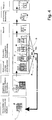
- the cuboidal mold 1 is used for casting an engine block M for an internal combustion engine, not further shown here.
- the mold 1 is composed as a core package of a plurality of casting cores.
- the casting cores are each prepared in known manner from a molding material which has been formed as a mixture of a molding sand and an organic binder and optionally optionally added additives in a core shooter, not shown here to the casting cores, which then solidified by gassing with a reaction gas have been.
- the cores may alternatively be used with any organic core manufacturing process known in the art, such as hot box, hot box, croning, hand molding and self-curing processes without catalysts.
- the casting cores of the casting mold 1 include a casting core 2, which forms the bottom of the casting mold 1 and on which the other casting cores of the casting mold 1 are constructed, two casting cores 3, 4, one of which is assigned to one of the longitudinal sides of the casting mold 1 and the delimiting the casting mold 1 on its longitudinal sides, two casting cores 5,6, one of which is assigned to one of the end faces of the casting mold 1 and which delimit the casting mold 1 at their end faces, and a cover core 7, which closes the casting mold 1 at its upper side.
- each more depressions 8.9 are formed in the lateral end of the mold 1 on the longitudinal sides forming cores 3,4 and the lateral end of the mold 1 at the end faces forming cores 5,6 each more depressions 8.9 are formed.
- the depressions 8, 9 are arranged in this way and are sunk into the respective casting core 3 - 6 over such a depth that, on the one hand, a wall thickness remains in the region of their bottom sufficient to confine the casting space enclosed by the casting mold 1, but on the other hand between the depressions 8,9 only webs 10,11 remain with a thickness which ensures sufficient strength for the dimensional stability of the respective casting core 3 - 6, but at the same time a simple fracture of the webs 8,9 and concomitantly the respective casting core 3 - 6, when the binder of the molding material from which the cores 3 - 6 are formed becomes ineffective.
- cover core 7 four perpendicular to the flat outer top surface 12 of the cover core 7 aligned and arranged at regular intervals through holes 13 - 16 are formed, which lead from the top surface 12 in the space enclosed by the casting cores 2-7.
- the passage openings 13-16 can also be closed with a membrane-like covering layer which is connected in one piece to the surrounding core material of the cover core 7 and which, when exposed to the temperature prevailing during the heat treatment, rapidly shatters and the respective passage opening 13 - 16 releases.
- the lids E have been omitted, the free passages D1-D4 provided in accordance with the invention and designed in the manner explained below can be recognized by the casting mold 1.
- each two stacked annular casting cores 18a, 18b are seated on a central casting core 17 depicting the upper part of the crank space K of the engine block casting M in a seat provided for this purpose.
- the G cordkerncrue 18 a, 18 b, 19 a, 19 b, 20 a, 20 b and 21 a, 21 b define with their outer peripheral surfaces each one of the four cylinder chambers of the engine block casting M, of which Fig. 4 For clarity, only three cylinder chambers Z1 - Z3 are shown symbolically.
- the cylinder chambers each form a passage opening of the engine block casting M.
- the annular openings enclosed by the casting cores 18a-21b are simultaneously aligned with each other and with respect to the respective associated passage openings 13-16 of the closely associated on the associated edge of the respective upper casting core 18b, 19b 20b, 21b seated cover core 7, so that they form the continuation of the through holes 13-16.
- a further passage opening 22-25 is formed in the plate-shaped casting core 17, which is likewise arranged in alignment with the associated passage opening 13-16 of the cover core 7 ,
- the passage openings 22 - 25 each pass into a passage opening 26 - 29.
- the through-holes 26-29 are funnel-shaped in the direction of the bottom core 2 widening formed in a further casting core 30 which forms the lower part of the crank chamber K and sits on the bottom core 2.
- the passage openings 14, 23, 27 and 32 aligned with one another and aligned coaxially with a common longitudinal axis L2 arranged axially parallel to the longitudinal axis L1 together with the annular openings delimited by the casting cores 19a, 19b form a second passage D2 which is aligned and coaxial with one another a common axis-parallel to the longitudinal axis L1 arranged longitudinal axis L3 aligned through holes 15,24,28 and 33 together with the annular grooves defined by the cores 20a, 20b ring openings a third passage D3 and the mutually aligned and coaxial with a common also axially parallel to the longitudinal axis L1 arranged longitudinal axis L4 aligned passage openings 16,25,29 and 34 together with the annular openings bounded by the casting cores 21a, 21b, a fourth passage D4.
- the casting mold 1 is assembled in a first processing station from the casting cores 2 - 7, 17, 18a - 21b and 30 and further casting cores not shown here for the sake of clarity.
- the mold 1 is filled with aluminum melt.
- the mold 1 is a horizontal aligned axis of rotation aligned so that it is above and the cover core 2 arranged in the direction of gravity below.
- the mold 1 is again pivoted about the horizontally oriented pivot axis, so that now the feeder and the cover core 7 are at the top, while the feed opening of the feeder is arranged in the direction of gravity below.
- This method also referred to as "rotational casting" achieves uniform solidification of the casting in the casting mold 1.
- the mold 1 runs into a continuous furnace O, in which the engine block M entsandet, the engine block M undergoes a solution annealing and falling of the engine block M molding material of the cores of the mold 1 for reprocessed.
- the casting mold 1 entering the furnace 0 is heated to the solution annealing temperature, which is typically in the range of 450-550 ° C., depending on the respectively processed Al casting alloy.
- This solution annealing temperature is higher than the temperature at which the binder of the molding material of the casting cores of the casting mold 1 burns.
- the time required for the solution annealing treatment is also completed, so that the engine block casting M can be quenched to room temperature in a station immediately thereafter. This is followed by a mechanical processing in which the feeder is separated and further machining operations are performed on the engine block M. Finally, an outsourcing treatment is optionally carried out.
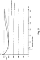
- Fig. 5 is the temperature profile of the engine block casting M in the furnace O for a gesandetes in conventional operation and solution-treated engine block casting (dashed line) and a similar in the inventive manner gesandetes and solution-annealed engine block casting (solid line) shown.
- the casting molds containing the respective casting have entered the furnace 0 after falling below the liquidus temperature of the molten aluminum from which the castings have been cast, but with the solidification of the respective engine block casting not yet completed.
- the engine block castings are passed in the only partially solidified state in the furnace 0, they can still be used in this state inherent casting heat.
- the temperature of the casting was in conventional and inventive operation when entering the furnace 0 each about 430 ° C.
- the casting gas flowed through by hot gas according to the invention has reached the solution annealing temperature TLG of approximately 485 ° C., much faster than the conventionally heated casting without casting.
- the hot-gas-flowed casting in the conventional furnace 0 lingered at the solution annealing temperature TLG for about 90 minutes longer than the conventionally treated casting. Since, at the same time, desanding was much more effective in the procedure according to the invention, the procedure according to the invention thus makes it possible to shorten the desanding and solution annealing process by about 30% compared to the conventional procedure.
Description
Die Erfindung betrifft ein Verfahren zum Entformen eines aus einer Leichtmetallschmelze gegossenen Gussteils aus einer Gießform. Die Gießform umfasst dabei mindestens einen Gießkern, der im Gussteil eine zwei Außenseiten des Gussteils verbindende Durchgangsöffnung abbildet und aus einem Formstoff hergestellt ist, der mittels eines unter Temperatureinwirkung zerfallenden Binders gebunden ist. Zum Entformen wird die Gießform in einem Ofen einer Wärmebehandlung unterzogen, bei der sie auf eine Temperatur erwärmt wird, bei der der Binder des Gießkerns seine Bindewirkung verliert. Ein Verfahren dieser Art wird in der
Solche in der Fachwelt auch als "thermisches Entsanden" bekannte Verfahren werden in der Praxis insbesondere beim Guss von Motorblöcken oder Zylinderköpfen für Verbrennungsmotoren aus Leichtmetall in großem Umfang eingesetzt. Gussteile dieser Art werden wegen ihrer in der Regel komplex filigranen Formgebung häufig in Gießformen gegossen, die als so genanntes "Kernpaket" aus einer Vielzahl von jeweils aus Formstoff vorgefertigten Einzelkernen zusammengesetzt sind. Aus Formstoff hergestellte Gießkerne werden jedoch auch beim Kokillenguss eingesetzt, um im inneren Bereich des jeweiligen Gussteils vorgesehene Kanäle und Durchgangsöffnungen abzuformen.Such known in the art as "thermal Entsanden" known methods are used in practice, especially in the casting of engine blocks or cylinder heads for internal combustion engines made of light metal on a large scale. Castings of this type are often poured because of their usually complex filigree shape in molds, which are composed as a so-called "core package" of a variety of each prefabricated from molding material single cores. Molded cores are also used in chill casting, however, in order to mold channels and passage openings provided in the inner region of the respective casting.
Die Formstoffe, aus denen die Gießkerne der hier in Rede stehenden Art geformt sind, bestehen üblicherweise aus einer Mischung aus einem geeigneten Formsand und dem Binder, der beim fertigen Gießkern die einzelnen Partikel des Formsands aneinander bindet und so die erforderliche Formstabilität des aus dem Formstoff geformten Kerns gewährleistet. Zusätzlich kann der Formstoff bestimmte Additive enthalten, die das Zusammenspiel von Binder und Formsand oder das Verhalten des jeweiligen Gießkerns beim Abguss der Schmelze verbessern.The molding materials from which the casting cores of the type in question are formed, usually consist of a mixture of a suitable molding sand and the binder, which binds the individual particles of the molding sand together in the finished casting core and thus the required dimensional stability of molded from the molding material Kerns guaranteed. In addition, the molding material may contain certain additives which improve the interaction of binder and foundry sand or the behavior of the respective casting core during casting of the melt.
Bei dem Binder kann es sich um einen durch Wärmezufuhr verfestigbaren anorganischen oder einen durch Begasung mit einem Reaktionsgas verfestigbaren organischen Binder handeln. Gemeinsam ist diesen Bindern, dass sie ihre Wirkung verlieren, wenn eine bestimmte obere Grenztemperatur überschritten wird und der Binder zumindest teilweise verbrennt. Sobald dieser Punkt erreicht ist, zerfallen die unter Verwendung solcher Binder hergestellten Gießkerne in Bruchstücke oder einzelne Sandpartikel, die von dem Gussteil abfallen. Ziel ist es dabei, den Zerfall der Gießkerne so zu steuern, dass möglichst geringe Mengen an Formstoff in oder an dem Gussteil zurückbleiben.The binder may be an inorganic binder which can be hardened by supplying heat or an organic binder which can be solidified by gassing with a reaction gas. What is common to these binders is that they lose their effect when a certain upper limit temperature is exceeded and the binder at least partially burns. Once this point is reached, the cores produced using such binders disintegrate into fragments or individual sand particles which fall off the casting. The aim is to control the disintegration of the casting cores so that the smallest possible amounts of molding material remain in or on the casting.
In der Praxis wird die Temperatur, bei der die für die thermische Entsandung durchgeführte Wärmebehandlung stattfindet, so hoch eingestellt, dass der Binder im Ofen weitestgehend vollständig verbrennt. Der zurückbleibende Formsand kann dann mit geringem Aufwand für eine erneute Verwendung aufbereitet werden.In practice, the temperature at which the heat treatment carried out for the thermal desanding takes place is set so high that the binder burns completely completely in the oven. The remaining molding sand can then be processed with little effort for reuse.
Besonders effektiv kann das thermische Entsanden genutzt werden, wenn, wie beispielsweise aus der
Lösungsglühbehandlung des Gussteils gekoppelt werden und diese drei Arbeitsschritte im kontinuierlichen Durchlauf in einem Ofen absolviert werden. Um das Ergebnis der Aufbereitung des Formsands zu verbessern, werden die von den Gussteilen abfallenden Bruchstücke der Gießkerne im Ofen in einem Formsandbett aufgefangen, das durch Einblasen eines Fluidgasstroms so fluidisiert wird, dass die Bruchstücke des Formsands beständig in Bewegung sind und in Folge ihrer dadurch erzwungenen abrasiven Belastung schnell in ihre einzelnen Sandpartikel zerfallen.The thermal sanding can be used particularly effectively if, for example, from the
Solution annealing treatment of the casting are coupled and completed these three steps in a continuous flow in an oven. In order to improve the result of the molding sand processing, the debris from the castings is collected in the furnace in a sand bed which is fluidized by blowing in a stream of fluid gas in such a way that the chips of the molding sand are constantly in motion and consequently forced abrasive load quickly disintegrate into their individual sand particles.
Die Verkopplung von thermischem Entsanden, Aufbereitung des Formsands und Lösungsglühbehandlung des Gussteils bedingt eine vergleichbar lange Aufenthaltsdauer der Gussteile im jeweiligen Ofen. Wenn für eine betriebsgerecht großtechnische Umsetzung bei Verfahren der hier in Rede stehenden Art die Gießformen und Gussteile im kontinuierlichen Durchlauf wärmebehandelt werden sollen, führt dies zu Durchlauföfen beträchtlicher Länge. Auch zeigt sich, dass die thermische Entsandung von Gießkernen, die im Gussteil Durchgangsöffnungen abbilden, selbst dann nur unvollkommen zuverlässig gelingt, wenn es sich bei diesen Durchgangsöffnungen um Zylinderöffnungen oder desgleichen handelt, die einen großen Durchmesser besitzen.The coupling of thermal sanding, preparation of the molding sand and solution annealing treatment of the casting requires a comparably long residence time of the castings in the respective furnace. If the casting molds and castings are to be heat-treated in a continuous pass for operationally large-scale implementation in processes of the type in question, this leads to continuous furnaces of considerable length. It is also found that the thermal desanding of casting cores, which portray passage openings in the casting, is only imperfectly reliable even if these passage openings are cylinder openings or the like, which have a large diameter.
Vor dem Hintergrund des voranstehend erläuterten Standes der Technik bestand die Aufgabe zu Grunde, die Effektivität und das Entsandungsergebnis eines Verfahrens der eingangs angegebenen Art zu verbessern.Against the background of the prior art explained above, the object was based on improving the effectiveness and the desanding result of a method of the type specified in the introduction.
Die Erfindung schlägt zur Lösung dieser Aufgabe das in Anspruch 1 angegebene Verfahren vor.The invention proposes to solve this problem, the method specified in
Vorteilhafte Ausgestaltungen des erfindungsgemäßen Verfahrens sind in den abhängigen Ansprüchen angegeben und werden nachfolgend wie der allgemeine Erfindungsgedanke im Einzelnen erläutert.Advantageous embodiments of the method according to the invention are specified in the dependent claims and are explained below as the general inventive concept in detail.
Wie beim thermischen Entsanden der voranstehend erläuterten Art wird gemäß der Erfindung beim Entformen eines aus einer Leichtmetallschmelze gegossenen Gussteils aus einer Gießform, die mindestens einen Gießkern umfasst, der in dem Gussteil eine zwei Außenseiten des Gussteils verbindende Durchgangsöffnung abbildet und aus einem Formstoff hergestellt ist, der mittels eines unter Temperatureinwirkung zerfallenden Binders gebunden ist, die Gießform zum Entformen in einem Ofen einer Wärmebehandlung unterzogen, bei der sie auf eine Temperatur erwärmt wird, bei der der Binder des Gießkerns seine Bindewirkung verliert..As in the thermal sands of the type described above, according to the invention, during demolding of a cast from a light metal melt casting from a mold comprising at least one casting core, which forms in the casting a two outer sides of the casting connecting through hole and is made of a molding material, which is bonded by means of a binder decomposing under the influence of temperature, the mold subjected to a heat treatment for demolding in an oven, in which it is heated to a temperature at which the binder of the casting core loses its binding effect.
Erfindungsgemäß wird nun im Ofen ein Durchgang, der in dem die Durchgangsöffnung abbildenden Gießkern der Gießform ausgebildet ist von Heißgas durchströmt, dessen Temperatur mindestens der Temperatur entspricht, bei der der Binder des Formstoffs seine Bindewirkung verliert, so dass der die Durchgangsöffnung abbildende Gießkern in Folge der Einwirkung des Heißgases zu Bruchstücken oder einzelne Sandpartikel zerfällt. Der Durchgang der Gießform ist dabei in dem die Durchgangsöffnung abbildenden Gießkern so angelegt, dass er von einer ersten Außenseite zu einer anderen Außenseite der Gießform führt.According to the invention, a passage which is formed in the casting core of the casting mold which images the through-opening is flowed through by hot gas whose temperature corresponds at least to the temperature at which the binder of the molding material loses its binding effect, so that the casting core forming the through-hole emerges Exposure of the hot gas to fragments or disintegration of individual particles of sand. In this case, the passage of the casting mold is arranged in the casting core which images the passage opening in such a way that it leads from a first outside to another outside of the casting mold.
Wenn hier vom "Verlust der Bindewirkung" gesprochen wird, ist dabei jeweils gemeint, dass der Binder in Folge eines zumindest teilweisen Verbrennens oder einer anderen Art von chemischem Zerfall zumindest stellenweise nicht mehr in der Lage ist, den Formstoff des Gießkerns zusammenzuhalten.Whenever the term "loss of binding effect" is used, it is meant in each case that the binder is at least in places unable to hold together the molding material of the casting core as a result of at least partial combustion or another type of chemical decomposition.
Der erfindungsgemäß vorgesehene Durchgang der Gießform kann schon bei Eintritt in den Ofen vorhanden sein. Dabei kann zur Vermeidung eines zu frühen Unwirksamwerdens des Binders die Durchgangsöffnung zunächst durch ein Hilfsmittel, wie einen dünnen Deckel aus brennbarem Material, z.B. Pappe, Sand, brennbarem Flies oder desgleichen verschlossen werden. Auf diese Weise wird der Gefahr entgegengewirkt, dass es im Bereich des Durchgangs schon vor dem Eintritt in den Ofen aufgrund des Kamineffektes zu einer Durchströmung des Durchgangs mit Luft aus der Umgebung und damit einhergehend zu einer vorzeitigen Verbrennung des Binders des die Durchgangsöffnung des Gussteils abbildenden Gießkerns. Der Deckel verbrennt nach sehr kurzer Zeit im Ofen, sodass der erfindungsgemäß genutzte Effekt, nämlich die Durchströmung des Durchgangs mit Heißgas im Ofen entsteht.The inventively provided passage of the mold may already be present upon entry into the oven. In this case, in order to avoid too early inactivation of the binder, the through-opening may be first by an aid, such as a thin lid of combustible material, e.g. Cardboard, sand, flammable fleece or the like. In this way, the risk is counteracted that, in the region of the passage, even before entry into the furnace due to the chimney effect, a flow through the passage with air from the environment and, consequently, premature combustion of the binder of the casting core forming the passage opening of the casting , The lid burns after a very short time in the oven, so that the effect used in the invention, namely the flow through the passage of hot gas is produced in the oven.
Alternativ ist es auch möglich, den Durchgang erst im Ofen auszubilden, beispielsweise dadurch, dass die Gießform so ausgebildet ist, dass der Durchgang freigegeben wird, wenn in Folge der Zersetzung des Binders ein erstes Formteil von der Gießform abfällt, oder dadurch, dass der Durchgang im Eingangsbereich des Ofens durch mechanische Krafteinwirkung in die Gießform eingebracht wird.Alternatively, it is also possible to form the passage first in the oven, for example by the mold being designed so that the passage is released when, as a result of the decomposition of the binder, a first mold part falls off the mold, or in that the passage is introduced into the mold by mechanical force in the entrance area of the furnace.
Gemäß der Erfindung wird also eine Gießform eingesetzt, die so ausgebildet ist, dass die Intensität, mit der sie der bei der Wärmebehandlung herrschenden heißen Atmosphäre ausgesetzt ist, gegenüber der konventionellen Vorgehensweise deutlich erhöht ist. Hierzu ist an der Gießform mindestens ein Durchgang vorgesehen, über den aus der Ofenatmosphäre gebildetes Heißgas auch zu innen im Gussteile liegenden Gießkernen der Gießform gelangt. Auf diese Weise werden auch die im Inneren des Gussteils angeordneten Gießkerne schnell auf eine Temperatur erwärmt, bei der ihr Binder seine Wirkung verliert. Dies gilt zuerst für den Gießkern, der mit dem vom Heißgas durchströmten Durchgang versehen ist, jedoch auch, sofern vorhanden, für die an ihn angrenzenden Gießkerne, die weitere Kanäle, Kavitäten und desgleichen im Gussteil abbilden.According to the invention, therefore, a mold is used, the is formed so that the intensity with which it is exposed to the ruling in the heat treatment hot atmosphere, compared to the conventional approach is significantly increased. For this purpose, at least one passage is provided on the casting mold, via which hot gas formed from the furnace atmosphere also passes to casting cores of the casting mold lying inside the castings. In this way, the cores arranged in the interior of the casting are heated quickly to a temperature at which their binder loses its effect. This applies first to the casting core which is provided with the through-flow of hot gas, but also, if present, for the casting cores adjacent to it, which image further channels, cavities and the like in the casting.
Bei üblichen Wärmebehandlungsöfen für Gießformen und Gussteile der hier in Rede stehenden Art enthält die Ofenatmosphäre Sauerstoff, so dass auch das durch den erfindungsgemäß vorgesehenen Durchgang der Gießform geleitete Heißgas Sauerstoff enthalten kann. Der besondere Vorteil der erfindungsgemäß vorgesehenen Durchströmung der Gießform mit Heißgas besteht dann darin, dass mit dem Heißgas auch in die innenliegenden Bereiche der Gießform gezielt größere Mengen an Sauerstoff gelangen, wodurch die Verbrennung des Formstoff-Binders gefördert und dementsprechend der Zerfall auch der innenliegenden Gießkerne beschleunigt und vervollständigt wird.In conventional heat treatment furnaces for casting molds and castings of the type in question, the furnace atmosphere contains oxygen, so that the hot gas passed through the passage of the casting mold provided according to the invention may also contain oxygen. The particular advantage of the inventively provided flow through the mold with hot gas then consists in that with the hot gas in the inner regions of the mold selectively reach greater amounts of oxygen, thereby promoting the combustion of the molding material binder and, accordingly, accelerates the disintegration of the inner casting cores and completed.
Neben dem beschleunigten Zerfall des Binders der Gießkerne führt die durch die erfindungsgemäße direkte Durchströmung von innen liegenden Gießkernen der Gießform mit Heißgas bewirkte beschleunigte Erwärmung zu erhöhten thermischen Spannungen in den Gießkerne, die ebenfalls zu einer erhöhten Effektivität und zu einem optimierten Ergebnis der erfindungsgemäß bewirkten thermischen Entsandung beitragen.In addition to the accelerated decomposition of the binder of the casting cores, the accelerated heating caused by the inventive direct flow from the inside of the casting cores of the casting mold with hot gas leads to increased thermal Stress in the cores, which also contribute to increased efficiency and to an optimized result of the present invention caused thermal desanding.
Grundsätzlich ist es denkbar, den erfindungsgemäß durch den in der Gießform vorgesehenen Durchgang strömenden Heißgasstrom durch ein Gebläse oder desgleichen zu erzwingen. Praktische Versuche haben jedoch gezeigt, dass auch die natürliche Konvektion ausreicht, um die erfindungsgemäß nutzbar gemachten Effekte zu erzielen. So tritt eine Kaminwirkung, durch die sich ein natürlicher Heißgasstrom durch den Durchgang bildet, in schon nahezu jeder beliebigen Ausrichtung des Durchgangs ein. Hierzu erweist es sich als besonders vorteilhaft, wenn der im Ofen von Heißgas durchströmte Durchgang des Gießkerns der Gießform im Ofen vertikal ausgerichtet ist. Dies lässt sich besonders leicht verwirklichen, wenn es sich bei den Leichtmetall-Gussteilen um Motorblöcke für Verbrennungsmotoren handelt, deren jeweils mindestens eine Zylinderöffnung und der angrenzende Kurbelraum durch mindestens einen in erfindungsgemäßer Weise mit einem Durchgang für das Heißgas versehenen Gießkern abgeformt wird.In principle, it is conceivable to force the hot gas stream flowing through the passage provided in the casting mold through a fan or the like. Practical experiments have shown, however, that the natural convection is sufficient to achieve the inventively made usable effects. Thus, a chimney effect, through which a natural flow of hot gas is formed through the passage, occurs in almost any orientation of the passage. For this purpose, it proves to be particularly advantageous if the flow in the furnace of hot gas passage of the casting core of the mold is aligned vertically in the oven. This can be achieved particularly easily if the light metal castings are engine blocks for internal combustion engines, each of which has at least one cylinder opening and the adjacent crankcase being shaped by at least one casting core provided with a passage for the hot gas in accordance with the invention.
Es versteht sich dabei von selbst, dass es entscheidend ist, dass der erfindungsgemäß vorgesehene Durchgang unabhängig davon vollständig durch die Gießform geführt ist, wie viele Gießkerne die jeweilige Durchgangsöffnung abformen. Dementsprechend kann bei einer für die Durchführung des erfindungsgemäßen Verfahrens vorgesehenen Gießform die Durchgangsöffnung des Gussteils durch zwei oder mehr Gießkerne abgebildet sein, die jeweils einen Durchgang ausweisen, wobei die Durchgänge der Gießkerne miteinander verbunden und im Ofen gemeinsam von Heißgas durchströmt werden. Ein Beispiel für eine solche Ausgestaltung ist die oben bereits erwähnte Gießform für einen Motorblock für einen Verbrennungsmotor, bei dem die jeweilige Zylinderöffnung durch einen oder mehrere Gießkerne abgeformt wird, die auf einem weiteren Gießkern sitzen, der den Kurbelraum des Motorblocks abformt. Erfindungsgemäß sind sämtliche dieser Gießkerne mit einem Durchgang versehen, wobei diese Durchgänge optimaler Weise fluchtend ausgerichtet sind, so dass eine intensive ungehinderte Durchströmung mit Heißgas möglich ist.It goes without saying that it is crucial that the passage provided according to the invention is guided completely independently of the casting mold, as many casting cores form the respective passage opening. Accordingly, in the case of a casting mold provided for carrying out the method according to the invention, the through-opening of the casting can be imaged by two or more casting cores, each having one Identify passage, wherein the passages of the cores are connected to each other and flowed through in the furnace together by hot gas. An example of such an embodiment is the above-mentioned mold for an engine block for an internal combustion engine, in which the respective cylinder opening is formed by one or more casting cores sitting on another casting core, which forms the crankcase of the engine block. According to the invention, all of these cores are provided with a passage, these passages are aligned optimally aligned, so that an intensive unhindered flow with hot gas is possible.
Als besonders günstig hat sich die Erfindung bei solchen Gießformen herausgestellt, die als Kernpaket ausgebildet sind, das aus zwei oder mehr Gießkernen zusammengesetzt ist. Selbstverständlich kann dabei ein solches Kernpaket nicht nur Gießkerne, sondern in an sich bekannter Weise auch Kühlelemente aus Metall oder Cromerzsand, wie Kühleisen für die Lagergasse, die Zylinderbohrung oder andere hochbeanspruchte Bereiche des Verbrennungsmotors umfassen. Hierzu zählen auch Kühlkokillen, Kühleisenplatten, welche komplette Kerne ersetzen können, und alle vergleichbaren Funktionsteile. Ebenso können in dem Kernpaket zylinderförmige so genannte "Liner" sitzen, die aus einem höher belastbaren Material als das Gussmaterial, aus dem der Motor gegossen ist und die im fertigen Verbrennungsmotor die Zylinderräume umgrenzen, in denen sich im Gebrauch die Kolben des Motors bewegen.To be particularly favorable, the invention has been found in such molds, which are formed as a core package, which is composed of two or more casting cores. Of course, such a core package may include not only cores, but in a conventional manner also cooling elements made of metal or Cromerzsand, such as cooling iron for the storage lane, the cylinder bore or other highly stressed areas of the engine. These include cooling molds, cooling iron plates, which can replace complete cores, and all comparable functional parts. Likewise, in the core package cylindrical so-called "liners" sitting, which consist of a higher loadable material than the casting material from which the engine is poured and which define the cylinder chambers in the finished internal combustion engine, in which move the pistons of the engine in use.
Die durch die erfindungsgemäße Gestaltung der Gießform bewirkte schnelle und intensive Durchwärmung führt gerade bei Kernpaket-Gießformen zu hohen thermischen Spannungen und einem intensiven Abbrand des Binders, wodurch der vollständige Zerfall der innen und außenliegenden Gießkerne begünstigt wird. So konnte gezeigt werden, dass bei einer erfindungsgemäß erfolgenden thermischen Entsandung von Motorblöcken der Sand der mit dem heißgasführenden Durchgang versehenen Gießkerne, die den Kurbelraum und die Zylinderöffnungen des Motorblocks abbilden, weitestgehend rückstandsfrei entfernt wurde und auch die außen liegenden Gießkerne zu einem deutlich größeren Teil entfernt werden konnten als dies bei konventioneller Vorgehensweise möglich ist.The effect of the inventive design of the mold rapid and intensive heating just leads in core-package casting molds, high thermal stresses and intensive burning of the binder, which favors the complete disintegration of the inner and outer casting cores. It has thus been shown that, in the case of a thermal desanding of engine blocks according to the invention, the sand of the casting cores provided with the hot gas-carrying passage, which depict the crank space and the cylinder openings of the engine block, has been removed as far as possible without residue, and also the outer casting cores are removed to a significantly greater extent could be achieved than is possible with conventional methods.
Die Effektivität der Entsandung der außen liegenden Gießkerne eines Gießform-Kernpakets lässt sich dadurch noch verbessern, dass in die die äußeren Seitenteile der Gießform bildenden Gießkerne des Kernpakets Einsenkungen eingeformt sind. Durch diese Einsenkungen wird nicht nur in an sich bekannter Weise Formsand und damit einhergehend Gewicht der Gießform gespart, sondern auch die Angriffsfläche für das Heißgas vergrößert. Auf diese Weise gelangen große Mengen Sauerstoff tief in den das jeweilige Seitenteil bildenden Gießkern, so dass dessen Binder in verkürzter Zeit weitestgehend vollständig verbrennt.The effectiveness of the desanding of the outer casting cores of a core mold package can be further improved in that depressions are formed in the cores of the core package which form the outer side parts of the casting mold. These depressions not only save in a conventional manner molding sand and concomitantly weight of the mold, but also increases the attack surface for the hot gas. In this way, large amounts of oxygen reach deep into the core forming the respective side part, so that its binder burns completely for the most part in a shortened time.
Sofern es sich bei der Gießform um ein Kernpaket handelt, decken in der Regel plattenförmige Seitenteile die Gießform an ihrem Boden, Seiten und an ihrer Deckelseite ab. Insbesondere bei einer solcherart ausgestalteten Gießform hat es sich als besonders günstig erwiesen, wenn der mindestens eine die Durchgangsöffnung des Gussteils abbildende Gießkern an das jeweilige den äußeren Abschluss der Gießform bildende Seitenteil stößt und der Durchgang des die Durchgangsöffnung abbildenden Gießkerns in dem äußeren Seitenteil bis zur Außenfläche der Gießform fortgesetzt ist. Das dann auch durch den Durchgang des jeweiligen Seitenteils strömende Heißgas bewirkt, dass die an den Durchgang angrenzenden Bereiche des Seitenteils schnell erwärmt werden mit der Folge, dass der dort vorhandene Binder beschleunigt verbrennt und Spannungen entstehen, die den Zerfall des Seitenteils beschleunigen.Insofar as the casting mold is a core package, plate-shaped side parts generally cover the casting mold at its bottom, sides and on its cover side. In particular, in the case of a casting mold designed in this way, it has proved to be particularly favorable when the at least one casting core, which images the passage opening of the casting, adjoins the respective outer termination the mold forming side member abuts and the passage of the through hole forming casting core is continued in the outer side part to the outer surface of the mold. The then flowing through the passage of the respective side part hot gas causes the adjacent to the passage areas of the side part are heated quickly, with the result that the binder present there burns accelerated and stresses that accelerate the decay of the side part.
Als besonders effektiv hat sich die erfindungsgemäße Vorgehensweise dann erwiesen, wenn die Wärmebehandlung, der die Gießform in dem Ofen unterzogen wird, als Lösungsglühbehandlung des Gussteils durchgeführt wird. Die erfindungsgemäß erfolgende Durchströmung eines innenliegenden Durchgangs der Gießform mit Heißgas bewirkt nicht nur eine schnelle Erwärmung des jeweils mit dem Durchgang für das Heißgas versehenen Gießkerns, sondern begünstig auch eine beschleunigte und gleichzeitig gleichmäßigere Erwärmung des Gussteilvolumens, da nun im Ofen die Wärme nicht mehr ausschließlich von der Außenseite bis zum Inneren des Gussteils vordringen muss, sondern auch Wärme direkt in einen innenliegenden Bereich geleitet wird.The procedure according to the invention has proved to be particularly effective when the heat treatment which is subjected to the casting mold in the furnace is carried out as solution heat treatment of the casting. The present invention flowing through an internal passage of the mold with hot gas not only causes rapid heating of each provided with the passage for the hot gas core, but also promotes accelerated and at the same time more uniform heating of the casting volume, since now in the oven, the heat is no longer exclusively from The outside must penetrate to the inside of the casting, but also heat is passed directly into an interior area.
Genauso wie die an sich bekannte Verkopplung mit einem Lösungsglühen lässt sich in Kombination mit einer erfindungsgemäßen thermischen Entsandung die an sich bekannte Aufbereitung des Formstoffs verwirklichen, bei der die durch den Zerfall des Binders sich bildenden und von dem Gussteil abfallenden Bruchstücke aufgefangen und im Ofen gehalten werden, bis auch der in den Bruchstücken noch enthaltene Binder verbrannt ist. Die Zerlegung der Bruchstücke in einzelne Formsandpartikel kann dabei in ebenfalls bekannter Weise dadurch unterstützt werden, dass die aufgefangenen Bruchstücke im Ofen durch Einblasen eines Gasstroms in das sich aus den Bruchstücken im Ofen bildende Formstoffbett in Bewegung gehalten werden.Just as the known coupling with a solution annealing can be realized in combination with a thermal desanding invention, the per se known treatment of the molding material, in which the fragments formed by the decay of the binder and falling from the casting fragments are collected and kept in the oven until the binder still contained in the fragments is burnt. The decomposition of the Fragments in individual molding sand particles can be assisted in a likewise known manner by keeping the collected fragments in the furnace by blowing a stream of gas into the molding material bed which is formed from the fragments in the furnace.
Im Ergebnis gelingt es mit der Erfindung somit auf einfache Weise, Gussstücke schneller und effizienter thermisch zu entkernen als dies bei konventioneller Verfahrensweise möglich ist. In Folge des schnelleren Zerfalls und der schnellen Erwärmung auf die jeweilige Wärmebehandlungstemperatur kann die Aufenthalts- oder Durchlaufzeit, über die die jeweilige Gießform bei der zum Entsanden erforderlichen Wärmebehandlung im Wärmebehandlungsofen verweilt, deutlich reduziert werden. Dies gilt insbesondere dann, wenn die erfindungsgemäße Entsandung mit einer Lösungsglühbehandlung des Gussteils kombiniert wird. So konnte nachgewiesen werden, dass bei erfindungsgemäßer Vorgehensweise die Lösungsglühzeit, d.h. die Zeit, über die das Gussteil auf Lösungsglühtemperatur gehalten werden musste, deutlich verkürzt werden kann. Praktische Tests haben hier ergeben, dass bei erfindungsgemäßer Vorgehensweise die Durchlaufzeiten, die zum im Durchlauf erfolgenden Entsanden und Lösungsglühen von aus einer Aluminiumschmelze gegossenen Motorblöcken für Verbrennungsmotoren benötigt werden, bis zu 60 Minuten kürzer sein können als bei konventioneller Betriebsweise. Die praktischen Untersuchungen lassen erwarten, dass auch noch größere Verkürzungen möglich sind.As a result, with the invention, it is thus possible in a simple manner to corer castings faster and more efficiently thermally than is possible with conventional methods. As a result of the faster disintegration and the rapid heating to the respective heat treatment temperature, the residence time or throughput time, during which the respective casting mold lingers during the heat treatment required for desanding in the heat treatment furnace, can be significantly reduced. This applies in particular when the desanding according to the invention is combined with a solution annealing treatment of the casting. Thus, it could be demonstrated that the solution annealing time, i. E. the time over which the casting had to be kept at solution annealing temperature can be significantly reduced. Practical tests have shown here that, in accordance with the invention, the throughput times required for the continuous desanding and solution treatment of engine blocks cast from an aluminum melt for internal combustion engines can be up to 60 minutes shorter than in conventional operation. The practical investigations can be expected that even larger shortenings are possible.
Nach der erfindungsgemäß durchgeführten thermischen Entsandung verbleibt am Gussstück deutlich weniger Restsand als bei konventioneller Vorgehensweise, da sich nicht nur im Bereich der jeweiligen Durchgangsöffnung ein bessere Entkernung einstellt, sondern in Folge der schnelleren Aufheizung des Gussteils andere innenliegende Kerne der Gießform ebenfalls schneller aufgewärmt werden, so dass auch bei ihnen ein intensiver Zerfall des Binders einsetzt und sich damit einhergehend die betreffenden Kerne in kleine Bruchstücke und Sandpartikel zerlegen, die leicht aus dem Gussteil ausrieseln können. Auf diese Weise erfüllen erfindungsgemäß entsandete Gussteile höchste Qualitätsanforderungen, ohne dass dazu aufwändige Maßnahmen für die Entfernung von Restschmutz und -sand aus den am Gussteil abzubildenden Kanälen betrieben werden muss.After the thermal desanding carried out according to the invention, significantly less residual sand remains on the casting than in the conventional approach, since not only in the region of the respective passage opening sets better gutting, but other internal cores of the mold are also warmed up faster, as a result of the faster heating of the casting, so that even with them begins an intensive disintegration of the binder and himself along with that, break down the cores into small fragments and sand particles, which can easily trickle out of the casting. In this way, according to the invention sanded castings meet the highest quality requirements, without the need to operate expensive measures for the removal of residual dirt and sand from the channels to be imaged on the casting.
Durch den erfindungsgemäß bewirkten schnellen Zerfall der Gießkerne und die schnelle Aufheizung des Gussteils können die zum thermischen Entkernen und die für die gegebenenfalls damit kombinierte Lösungsglühbehandlung erforderlichen Wärmebehandlungszeiten reduziert werden. Dies wiederum erlaubt es, die für eine im Durchlauf erfolgende Durchführung des Verfahrens benötigten Öfen kürzer und damit preisgünstiger zu bauen und mit geringerem Energieaufwand zu betreiben. Durch den erfindungsgemäß vorgesehenen Durchgang wird zudem Formstoff und Gewicht eingespart, was zusätzlich zu der durch die erfindungsgemäße Vorgehensweise erzielte Kostenreduzierung beiträgt.As a result of the rapid disintegration of the casting cores and the rapid heating of the casting, the heat treatment times required for thermal coring and for the solution heat treatment optionally combined therewith can be reduced. This in turn makes it possible to build the furnaces needed for a run-through implementation of the method shorter and thus cheaper and operate with less energy. The passage provided according to the invention also saves mold material and weight, which in addition to the cost reduction achieved by the procedure according to the invention contributes.
Nachfolgend wird die Erfindung anhand einer ein Ausführungsbeispiel darstellenden Zeichnung näher erläutert. Es zeigen jeweils schematisch:
- Fig. 1
- eine Gießform in perspektivischer Ansicht;
- Fig. 2.
- die Gießform gemäß
Fig. 1 in einer Ansicht von oben; - Fig. 3
- die Gießform gemäß
Fig. 1 in einem Schnitt entlang der inFig. 1 eingetragenen Schnittlinie X-X - Fig. 4
- die Abfolge der bei der Herstellung eines Gussteils unter Einbindung des erfindungsgemäßen Verfahrens absolvierten Arbeitsschritte.
- Fig. 5
- die Temperaturentwicklung im Motorblock-Gussteils beim Durchlauf durch einen Durchlaufofen bis zum Erreichen der Lösungsglühtemperatur aufgetragen über die Zeit.
- Fig. 1
- a mold in perspective view;
- Fig. 2.
- the mold according to
Fig. 1 in a view from above; - Fig. 3
- the mold according to
Fig. 1 in a section along the inFig. 1 Registered section line XX - Fig. 4
- the sequence of completed in the production of a casting using the method according to the invention steps.
- Fig. 5
- the temperature development in the engine block casting when passing through a continuous furnace until the solution annealing temperature is applied over time.
Die quaderförmige Gießform 1 dient zum Gießen eines Motorblocks M für einen hier weiter nicht gezeigten Verbrennungsmotor.The
Die Gießform 1 ist als Kernpaket aus einer Vielzahl von Gießkernen zusammengesetzt. Die Gießkerne sind jeweils in an sich bekannter Weise aus einem Formstoff hergestellt, der als Mischung aus einem Formsand und einem organischen Binder sowie gegebenenfalls optional zugefügten Additiven in einer hier nicht dargestellten Kernschießmaschine zu den Gießkernen geformt worden ist, die anschließend durch Begasen mit einem Reaktionsgas verfestigt worden sind.The
Die Kerne können alternativ mit allen im Stand der Technik bekannten organischen Kernherstellungsverfahren, wie beispielsweise Warmbox, Hotbox, Croning, Handformverfahren und selbstaushärtende Verfahren ohne Katalysatoren, hergestellt sein.The cores may alternatively be used with any organic core manufacturing process known in the art, such as hot box, hot box, croning, hand molding and self-curing processes without catalysts.
Zu den Gießkernen der Gießform 1 zählen ein Gießkern 2, der den Boden der Gießform 1 bildet und auf dem die anderen Gießkerne der Gießform 1 aufgebaut sind, zwei Gießkerne 3,4, von denen jeweils einer einer der Längsseiten der Gießform 1 zugeordnet ist und die die Gießform 1 an ihren Längsseiten abgrenzen, zwei Gießkerne 5,6, von denen jeweils einer einer der Stirnseiten der Gießform 1 zugeordnet ist und die die Gießform 1 an ihren Stirnseiten abgrenzen, sowie ein Deckkern 7, der die Gießform 1 an ihrer Oberseite abschließt.The casting cores of the casting
In die den seitlichen Abschluss der Gießform 1 an deren Längsseiten bildenden Gießkerne 3,4 und die den seitlichen Abschluss der Gießform 1 an deren Stirnseiten bildenden Gießkerne 5,6 sind jeweils mehrere Einsenkungen 8,9 eingeformt. Die Einsenkungen 8,9 sind dabei so angeordnet und über eine solche Tiefe in den jeweiligen Gießkern 3 - 6 eingesenkt, dass einerseits im Bereich ihres Bodens eine Wandstärke verbleibt, die ausreicht, um den von der Gießform 1 umschlossenen Gießraum sicher zu umgrenzen, andererseits aber zwischen den Einsenkungen 8,9 jeweils nur Stege 10,11 mit einer Dicke verbleiben, die eine für die Formsteifigkeit des jeweiligen Gießkerns 3 - 6 ausreichende Festigkeit gewährleistet, gleichzeitig jedoch ein einfaches Zerbrechen der Stege 8,9 und damit einhergehend des jeweiligen Gießkerns 3 - 6 ermöglicht, wenn der Binder des Formstoffs, aus dem die Gießkerne 3 - 6 geformt sind, unwirksam wird.In the lateral end of the
In den Deckkern 7 sind vier senkrecht zur ebenen äußeren Deckfläche 12 des Deckkerns 7 ausgerichtete und in gleichmäßigen Abständen angeordnete Durchgangsöffnungen 13 - 16 eingeformt, die von der Deckfläche 12 in den von den Gießkernen 2 - 7 umschlossenen Raum führen.In the
In den an die Deckfläche 12 angrenzenden Randbereich der Durchgangsöffnungen 6 ist ein umlaufender Absatz eingeformt. Auf diesem Absatz sitzt jeweils ein aus dem Formstoff, aus dem auch der Deckkern 7 selbst geformt ist, aus Pappe oder brennbarem Filz hergestellter, etwa 1 cm starker Deckel E, der lose in die Öffnung 13 - 16 gelegt ist, um die Durchgangsöffnungen 13 - 16 nach dem Abgießen des Motorblock-Gussteils M geschlossen zu halten, bis die zum Entsanden und Lösungsglühen durchgeführte Wärmebehandlung beginnt. Alternativ zu einem separaten Deckel E können die Durchgangsöffnungen 13 - 16 auch mit einer membranartigen, einstückig mit dem umgebenden Kernmaterial des Deckkerns 7 verbundenen Deckschicht verschlossen sein, die, wenn sie der bei der Wärmebehandlung herrschenden Temperatur ausgesetzt ist, schnell zerbricht und die jeweilige Durchgangsöffnung 13 - 16 freigibt. In den
In dem von den Gießkernen 2 - 7 umschlossenen Raum sitzen auf einem zentralen den oberen Teil des Kurbelraums K des Motorblock-Gussteils M abbildenden Gießkern 17 in einem dafür jeweils vorgesehenen Sitz vier Paare von jeweils zwei aufeinander gestapelten ringförmigen Gießkernen 18a,18b, 19a,19b, 20a,20b und 21a,21b. Die Gießkernpaare 18a,18b, 19a,19b, 20a,20b und 21a,21b grenzen mit ihren äußeren Umfangsflächen jeweils einen der vier Zylinderräume des Motorblock-Gussteils M ab, von denen in
In Verlängerung des Ringraums des jeweils unteren Gießkerns 18a,19a,20a,21a der Gießkerne 18a-21b ist in den plattenförmigen Gießkern 17 jeweils eine weitere Durchgangsöffnung 22 - 25 eingeformt, die ebenfalls fluchtend zu der zugeordneten Durchgangsöffnung 13 - 16 des Deckkerns 7 angeordnet ist.In the extension of the annular space of the respective
An ihrem unteren dem Bodenkern 2 zugeordneten Ende gehen die Durchgangsöffnungen 22 - 25 jeweils in eine Durchgangsöffnung 26 - 29 über. Die Durchgangsöffnungen 26 - 29 sind sich trichterförmig in Richtung des Bodenkerns 2 erweiternd in einen weiteren Gießkern 30 eingeformt, der den unteren Teil des Kurbelraums K abformt und auf dem Bodenkern 2 sitzt.At their lower end associated with the
In den Bodenkern 2 sind schließlich vier weitere Durchgangsöffnungen 31 - 34 eingeformt, von denen jeweils eine einer der Durchgangsöffnungen 26 - 29 zugeordnet ist.Finally, four further passage openings 31 - 34 are formed in the
Die zueinander fluchtend und koaxial zu einer gemeinsamen Längsachse L1 ausgerichteten Durchgangsöffnungen 13,22,26 und 31 bilden gemeinsam mit den von den Gießkernen 18a,18b umgrenzten Ringöffnungen einen ersten Durchgang D1, der von der ebenen Aufstandfläche 35, mit der der Bodenkern 2 im Gebrauch auf dem jeweiligen Untergrund steht zur ebenfalls ebenen Deckfläche 12 des Deckkerns 7 führt.The through holes 13, 22, 26 and 31 aligned with one another in a coaxial manner with a common longitudinal axis L1, together with the annular openings delimited by the
In entsprechender Weise bilden die zueinander fluchtend und koaxial zu einer gemeinsamen achsparallel zur Längsachse L1 angeordneten Längsachse L2 ausgerichteten Durchgangsöffnungen 14,23,27 und 32 gemeinsam mit den von den Gießkernen 19a,19b umgrenzten Ringöffnungen einen zweiten Durchgang D2, die zueinander fluchtend und koaxial zu einer gemeinsamen achsparallel zur Längsachse L1 angeordneten Längsachse L3 ausgerichteten Durchgangsöffnungen 15,24,28 und 33 gemeinsam mit den von den Gießkernen 20a,20b umgrenzten Ringöffnungen einen dritten Durchgang D3 und die zueinander fluchtend und koaxial zu einer gemeinsamen ebenfalls achsparallel zur Längsachse L1 angeordneten Längsachse L4 ausgerichteten Durchgangsöffnungen 16,25,29 und 34 gemeinsam mit den von den Gießkernen 21a,21b umgrenzten Ringöffnungen einen vierten Durchgang D4.In a corresponding manner, the
Zum Herstellen eines Motorblocks M wird in einer ersten Verarbeitungsstation aus den Gießkernen 2 - 7, 17, 18a - 21b und 30 sowie weiteren hier der Übersichtlichkeit halber nicht gezeigten Gießkernen die Gießform 1 zusammengesetzt.To produce an engine block M, the casting
Anschließend wird die Gießform 1 mit Aluminiumschmelze gefüllt. Dabei ist die Gießform 1 um eine horizontal ausgerichtete Drehachse so ausgerichtet, dass sie oben und der Deckkern 2 in Schwerkraftrichtung unten angeordnet ist. Auf diese Weise ist eine in den
Frühestens mit einsetzender und spätestens nach vollständiger Erstarrung der Aluminiumschmelze in der Gießform 1 läuft die Gießform 1 in einen Durchlaufofen O ein, in dem der Motorblock M entsandet, der Motorblock M eine Lösungsglühbehandlung durchläuft und der vom Motorblock M abfallende Formstoff der Gießkerne der Gießform 1 zur erneuten Verwendung aufbereitet wird.At the earliest with onset and at the latest after complete solidification of the molten aluminum in the
Die in den Ofen 0 einlaufende Gießform 1 wird dazu auf die Lösungsglühtemperatur erwärmt, die abhängig von der jeweils verarbeiteten Al-Gusslegierung typischerweise im Bereich von 450 - 550 °C liegt. Diese Lösungsglühtemperatur ist höher als die Temperatur, ab der der Binder des Formstoffs der Gießkerne der Gießform 1 verbrennt.The casting
In Folge der natürlichen Konvektion setzen dabei Heißgasströme H ein, die von unten durch die Durchgänge D1 - D4 der Gießform 1 strömen. Auf diese Weise beginnt der Zerfall der Gießform 1 nicht nur im Bereich der äußeren Gießkerne 2 - 7, sondern auch in den von den Heißgasströmen H1 - H4 erfassten Bereichen der Gießkerne 17, 18a - 21b und 30 im Inneren der Gießform 1. Gleichzeitig wird auch das Leichtmetall des Motorblocks M nicht nur von der Außenseite der Gießform 1 her, sondern auch von innen schnell auf die Lösungsglühtemperatur erwärmt.As a result of the natural convection, hot gas flows H, which flow from below through the passages D1-D4 of the casting
Mit fortschreitender Erwärmung und damit einhergehender Verbrennung des Binders ihres Formstoffs wird der Binder zunehmend unwirksam und die seitlichen Gießkerne 2 - 7 und die inneren Gießkerne 2 - 7, 17, 18a - 21b und 30 beginnen zu zerbrechen. Die von dem Motorblock-Gussteil M abfallenden Bruchstücke und Sandpartikel B werden in einem unter dem Förderweg F der Gießform 1 im Ofen 0 vorgesehenen Sandbett SB aufgefangen.As the heating progresses and the combustion of the binder of its molding material increases, the binder becomes increasingly ineffective and the lateral casting cores 2-7 and the inner casting cores 2-7, 17, 18a-21b and 30 begin to break. The falling of the engine block casting M fragments and sand particles B are collected in a provided under the conveying path F of the
Um die im Sandbett SB gesammelten Bruchstücke B in Bewegung zu halten, um ihre Zerkleinerung und Regenerierung zu fördern, wird über in den Boden des Ofens 0 eingelassene Düsen Heißgas HG in das Sandbett SB geblasen. Durch die so erzielte Fluidisierung und Temperierung des Sandbetts SB verbrennt der restliche in den Gießkern-Bruchstücken B noch enthaltene Binder und die Bruchstücke B werden in ihre einzelnen Sandpartikel zerlegt. Der durch diese Aufbereitung erhaltene Formsand S wird zur Wiederverwendung an die Kernschießmaschine zurückgeleitet, die die Gießkerne herstellt, aus der die jeweilige Gießform 1 zusammengesetzt wird.In order to keep the debris B collected in the sand bed SB in motion to promote its comminution and regeneration, hot gas HG is blown into the sand bed SB through nozzles set in the bottom of the
Je weiter das Motorblock-Gussteil M in Richtung des Ausgangs des Ofens 0 gefördert wird, umso vollständiger wird die Entsandung des Motorblocks M, bis schließlich auch kleinste Bruchstücke B aus ihm herausgerieselt sind.The farther the engine block casting M is conveyed in the direction of the exit of the
Mit Erreichen des Ausgangs des Ofens 0 ist dann auch die für die Lösungsglühbehandlung benötigte Zeit abgeschlossen, so dass das Motorblock-Gussteil M in einer unmittelbar anschließend durchlaufenen Station auf Raumtemperatur abgeschreckt werden kann. Daraufhin erfolgt eine mechanische Bearbeitung, bei der der Speiser abgetrennt und weitere spanabhebende Bearbeitungsoperationen an dem Motorblock M vorgenommen werden. Abschließend erfolgt dann optional noch eine Auslagerungsbehandlung.Upon reaching the exit of the
In
Die Temperatur des Gussteils betrug bei konventioneller und erfindungsgemäßer Betriebsweise bei Eintritt in den Ofen 0 jeweils ca. 430 °C. Das erfindungsgemäß von Heißgas durchströmte Gussteil hat die Lösungsglühtemperatur TLG von ca. 485 °C jedoch deutlich schneller erreicht als das konventionell ohne Durchströmung erwärmte Gussteil. Infolgedessen hat das erfindungsgemäß heißgasdurchströmte Gussteil im konventionellen Ofen 0 ca. 90 Minuten länger auf der Lösungsglühtemperatur TLG verweilt als das konventionell behandelte Gussteil. Da gleichzeitig die Entsandung bei erfindungsgemäßer Vorgehensweise wesentlich effektiver ablief, ermöglicht es somit die erfindungsgemäße Vorgehensweise, den Entsandungs- und Lösungsglühprozess um etwa 30 % gegenüber der konventionellen Verfahrensweise zu verkürzen.The temperature of the casting was in conventional and inventive operation when entering the
- 11
- Gießformmold
- 22
- Boden-GießkernGround casting core
- 3, 43, 4
-
die Längsseiten der Gießform 1 abgrenzende Gießkernethe longitudinal sides of the
mold 1 delimiting casting cores - 5, 65, 6
-
die Stirnseiten der Gießform 1 abgrenzende Gießkernethe end faces of the
mold 1 delimiting casting cores - 77
- Deckkerndeck core
- 8, 98, 9
- Einsenkungendepressions
- 10, 1110, 11
- StegeStege
- 1212
-
Deckfläche des Deckkerns 7Top surface of the
cover core 7 - 13 - 1613 - 16
- Durchgangsöffnungen des Deckkerns 7Through openings of the cover core. 7
- 1717
- Gießkerncasting core
- 18a - 21b18a - 21b
- ringförmige Gießkerneannular casting cores
- 22 - 2522 - 25
- Durchgangsöffnungen des Gießkerns 17Through openings of the casting core 17th
- 26 - 2926 - 29
- Durchgangsöffnungen des Gießkerns 30Through openings of the casting core 30th
- 3030
- Gießkerncasting core
- 31 - 3431 - 34
-
Durchgangsöffnungen des Bodenkerns 2Through holes of the
bottom core 2 - 3535
-
Aufstandfläche des Boden-Gießkerns 2Contact surface of the
bottom casting core 2
- BB
- Gießkern-BruchstückeCasting core fragments
- D1 - D4D1 - D4
- Durchgängecrossings
- Ee
- Deckelcover
- HH
- Heißgashot gas
- HGHG
- Heißgas-StrömeHot gas streams
- KK
- Kurbelraum des Motorblocks MCrankcase of engine block M
- MM
- Motorblock-GussteilEngine block casting
- OO
- DurchlaufofenContinuous furnace
- SS
- aufbereiteter Formsandprocessed molding sand
- SBSB
- Sandbettsand bed
- Z1 - Z3Z1 - Z3
- Zylinderräume des Motorblocks MCylinder chambers of the engine block M
- FF
- Förderwegconveying
Claims (10)
- Method for demoulding a casting (M), cast from a light metal melt, from a casting mould (1) which comprises at least one casting core (2-7, 17, 18a-21b, 30) which images a passage opening (Z1 - Z3) in the casting (M) connecting two outer sides of the casting and is produced from a moulding material which is bound by means of a binder which decomposes under the influence of temperature, wherein the casting mould (1) undergoes a heat treatment in a furnace (0) for the demoulding, during which it is heated to a temperature at which the binder loses its binding effect, characterised in that, in the furnace (0), a passage (D1-D4), which is formed in the casting core (18a-21b) of the casting mould (1) imaging the passage opening, is flowed through by hot gas (H), the temperature of which corresponds at least to the temperature at which the binder of the moulding material loses it binding effect such that the casting core (18a-21b) imaging the passage opening (Z1-Z3) decomposes into fragments (B) or separate sand particles as a consequence of the influence of the hot gas.
- Method according to claim 1, characterised in that the passage (D1-D4) of the casting core (18a-21b) of the casting mould (1) is aligned vertically in the furnace (O).
- Method according to one of the preceding claims, characterised in that the passage opening (Z1-Z3) of the casting (1) is imaged by two or more casting cores (18a-21b) which respectively have a passage (D1-D4), and that the passages (D1-D4) of the casting cores (18a-21b) allocated to a passage opening (Z1-Z3) are connected to one another and are flowed through together by hot gas (H) in the furnace (0).
- Method according to one of the preceding claims, characterised in that the casting mould (1) is formed as a core package composed of two or more casting cores (2-7, 17, 18a-21b, 30).
- Method according to claim 4, characterised in that indentations (8, 9) are moulded into the casting cores (3-6) which form the outer side parts of the casting mould (1).
- Method according to one of the preceding claims, characterised in that the at least one casting core (18a-21b) imaging the passage opening (Z1-Z3) of the casting (M) strikes a side part (7) which forms the outer border of the casting mould (1), and the passage (D1-D4) of the casting core (18a-21b) imaging the passage opening (Z1-Z3) is continued in the outer side part (7) until the outer surface (12) of the casting mould (1).
- Method according to one of the preceding claims, characterised in that the heat treatment which the casting mould (1) undergoes in the furnace (O) is carried out as a solution annealing treatment of the casting (M).
- Method according to one of the preceding claims, characterised in that the fragments (B) of at least the casting core (2-7, 17, 18a-21b, 30) imaging the passage opening, which are formed by the decomposition of the binder and which fall away from the casting (M), are collected and are held in the furnace (0) until the binder still contained in the fragments (B) is also combusted.
- Method according to one of the preceding claims, characterised in that the casting (M) is an engine block for a combustion engine, and that the passage opening imaged by the at least one casting core (18a-21b) is a cylinder opening (Z1-Z3) of this casting (M).
- Method according to one of the preceding claims, characterised in that the casting mould (1) and the casting (M) pass through the furnace (0) in a continuous run.
Applications Claiming Priority (1)
| Application Number | Priority Date | Filing Date | Title |
|---|---|---|---|
| PCT/EP2013/068277 WO2015032427A1 (en) | 2013-09-04 | 2013-09-04 | Method for removing a cast part cast from a light metal melt from a casting mould |
Publications (2)
| Publication Number | Publication Date |
|---|---|
| EP3041623A1 EP3041623A1 (en) | 2016-07-13 |
| EP3041623B1 true EP3041623B1 (en) | 2017-06-07 |
Family
ID=49111211
Family Applications (1)
| Application Number | Title | Priority Date | Filing Date |
|---|---|---|---|
| EP13756497.7A Active EP3041623B1 (en) | 2013-09-04 | 2013-09-04 | Method for removing a cast part cast from a light metal melt from a casting mould |
Country Status (10)
| Country | Link |
|---|---|
| US (1) | US9895745B2 (en) |
| EP (1) | EP3041623B1 (en) |
| JP (1) | JP6126746B2 (en) |
| KR (1) | KR101759268B1 (en) |
| CN (1) | CN105705274B (en) |
| BR (1) | BR112016004221B1 (en) |
| ES (1) | ES2634319T3 (en) |
| MX (1) | MX370862B (en) |
| RU (1) | RU2635598C2 (en) |
| WO (1) | WO2015032427A1 (en) |
Families Citing this family (2)
| Publication number | Priority date | Publication date | Assignee | Title |
|---|---|---|---|---|
| CN106583658B (en) * | 2016-12-14 | 2018-11-13 | 江西腾勒动力有限公司 | The method of motor cylinder casting sand core and the application casting sand core cast blocks |
| CN114918977B (en) * | 2022-06-20 | 2023-10-13 | 一汽丰田发动机(长春)有限公司 | Operation method for confirming manipulator coordinate adjustment standard part and part taking position |
Family Cites Families (12)
| Publication number | Priority date | Publication date | Assignee | Title |
|---|---|---|---|---|
| JPS51111421A (en) * | 1975-03-26 | 1976-10-01 | Kubota Ltd | Method of banking backup for precision casting mold |
| JPS62259661A (en) | 1986-05-07 | 1987-11-12 | Nissan Motor Co Ltd | Core breaking method in die casting |
| ES2107438T5 (en) | 1991-05-24 | 2004-04-01 | Consolidated Engineering Company, Inc. | METHOD AND APPARATUS FOR THERMALLY TREATING METALLIC COLORED PARTS. |
| BR9305607A (en) | 1992-08-13 | 1995-06-13 | Cons Eng Co | Apparatus and process for heat treating die casting with sand core, and apparatus for treating heat die casting |
| CA2254505A1 (en) * | 1997-12-22 | 1999-06-22 | Joseph C. Schim | Rapidly forming complex hollow shapes using lost wax investment casting |
| AU781487B2 (en) | 1999-07-29 | 2005-05-26 | Consolidated Engineering Company, Inc. | Heat treatment and sand removal for castings |
| CA2461797A1 (en) * | 2001-09-14 | 2003-03-27 | Bernhard Stauder | Method for producing castings, molding sand and its use for carrying out said method |
| MXPA05001393A (en) * | 2002-08-08 | 2005-04-28 | Cons Eng Co Inc | Methods and apparatus for heat treatment and sand removal for castings. |
| US7121318B2 (en) * | 2002-09-20 | 2006-10-17 | Alotech Ltd. Llc | Lost pattern mold removal casting method and apparatus |
| JP2006231360A (en) * | 2005-02-24 | 2006-09-07 | Suzuki Motor Corp | Method for separating and removing core and apparatus therefor |
| DE102005046027A1 (en) * | 2005-09-05 | 2007-03-08 | HOS Hottinger Systems GbR (vertretungsberechtigter Gesellschafter: Walter Leo Pöhlandt, 68782 Brühl) | Method for casting molded parts |
| CN102161224A (en) * | 2011-03-11 | 2011-08-24 | 王湘冀 | Hollow product injection molding method, fusible core of hollow product and manufacturing methods thereof |
-
2013
- 2013-09-04 JP JP2016529434A patent/JP6126746B2/en active Active
- 2013-09-04 US US14/916,374 patent/US9895745B2/en active Active
- 2013-09-04 CN CN201380079379.3A patent/CN105705274B/en active Active
- 2013-09-04 WO PCT/EP2013/068277 patent/WO2015032427A1/en active Application Filing
- 2013-09-04 EP EP13756497.7A patent/EP3041623B1/en active Active
- 2013-09-04 KR KR1020167007584A patent/KR101759268B1/en active IP Right Grant
- 2013-09-04 RU RU2016112524A patent/RU2635598C2/en active
- 2013-09-04 BR BR112016004221-2A patent/BR112016004221B1/en active IP Right Grant
- 2013-09-04 ES ES13756497.7T patent/ES2634319T3/en active Active
- 2013-09-04 MX MX2016002776A patent/MX370862B/en active IP Right Grant
Also Published As
| Publication number | Publication date |
|---|---|
| JP6126746B2 (en) | 2017-05-10 |
| CN105705274A (en) | 2016-06-22 |
| US20160193655A1 (en) | 2016-07-07 |
| RU2635598C2 (en) | 2017-11-14 |
| WO2015032427A1 (en) | 2015-03-12 |
| BR112016004221B1 (en) | 2019-06-11 |
| JP2016530101A (en) | 2016-09-29 |
| MX370862B (en) | 2020-01-08 |
| US9895745B2 (en) | 2018-02-20 |
| EP3041623A1 (en) | 2016-07-13 |
| CN105705274B (en) | 2017-07-25 |
| KR101759268B1 (en) | 2017-07-18 |
| MX2016002776A (en) | 2016-08-03 |
| ES2634319T3 (en) | 2017-09-27 |
| KR20160047514A (en) | 2016-05-02 |
| RU2016112524A (en) | 2017-10-09 |
Similar Documents
| Publication | Publication Date | Title |
|---|---|---|
| EP2844409B1 (en) | Method for casting a cast part provided with at least one passage opening | |
| EP2091678B1 (en) | Casting mould for casting a cast part and use of such a casting mould | |
| DE102014101080B3 (en) | Device for producing a cylinder crankcase in low-pressure or gravity casting | |
| EP2945760B1 (en) | Casting mold for producing castings, in particular cylinder blocks and cylinder heads, having functional connection of the feeder | |
| EP3597329A1 (en) | Method for casting castings | |
| DE102008058329A1 (en) | Method for tempering a hot isostatic press and a hot isostatic press | |
| EP0872295A1 (en) | Casting mould and method for the production of hollow castings and hollow castings | |
| DE102009049695A1 (en) | Method for producing a rotor of a turbocharger | |
| EP3041623B1 (en) | Method for removing a cast part cast from a light metal melt from a casting mould | |
| EP3166740B1 (en) | Core and mehtod for the production of a core | |
| DE102008037778A1 (en) | Casting device comprises casting units having a mold with a feeder, a rotatable turntable on which the casting units are arranged, means for introducing molten metal in the mold, and a robot apparatus arranged on a rotating device | |
| EP0890400B1 (en) | Casting method for making metallic mouldings | |
| EP2636467B1 (en) | Device for manufacturing a cylinder crank case in V design | |
| EP2734322B1 (en) | Casting core of a casting mould for producing a cylinder | |
| DE102015217452A1 (en) | Method for producing a cast metallic bearing housing | |
| EP0415135B1 (en) | Method for manufacturing brake discs | |
| EP3285941B1 (en) | Core box for producing casting cores | |
| EP3055088A1 (en) | Casting mould and piston produced with the casting mould | |
| DE102012217939A1 (en) | Process for the production of cores for the casting production of workpieces | |
| DE102017106775A1 (en) | Casting core and process for its production | |
| EP2312063B1 (en) | Cover with wear-resistant surface and method for its production | |
| DE3002576A1 (en) | PERMANENT FORM (CHOCOLATE) FOR THE PRODUCTION OF CASTING PIECES FROM LIGHT METAL | |
| DE102012019192A1 (en) | Aluminum casting core comprises sand core part, and salt core part, where sand core part partially, positively surrounds salt core part and wall thickness of the sand core part is thinner relative to a wall thickness of the salt core part | |
| DE2500661A1 (en) | Wear resistant parts for crushing machinery - using steel castings contg. white martensitic cast iron inserts for long life | |
| WO2022263517A1 (en) | Process for casting of cast parts |
Legal Events
| Date | Code | Title | Description |
|---|---|---|---|
| PUAI | Public reference made under article 153(3) epc to a published international application that has entered the european phase |
Free format text: ORIGINAL CODE: 0009012 |
|
| 17P | Request for examination filed |
Effective date: 20160229 |
|
| AK | Designated contracting states |
Kind code of ref document: A1 Designated state(s): AL AT BE BG CH CY CZ DE DK EE ES FI FR GB GR HR HU IE IS IT LI LT LU LV MC MK MT NL NO PL PT RO RS SE SI SK SM TR |
|
| AX | Request for extension of the european patent |
Extension state: BA ME |
|
| DAX | Request for extension of the european patent (deleted) | ||
| GRAP | Despatch of communication of intention to grant a patent |
Free format text: ORIGINAL CODE: EPIDOSNIGR1 |
|
| INTG | Intention to grant announced |
Effective date: 20161221 |
|
| GRAS | Grant fee paid |
Free format text: ORIGINAL CODE: EPIDOSNIGR3 |
|
| AK | Designated contracting states |
Kind code of ref document: B1 Designated state(s): AL AT BE BG CH CY CZ DE DK EE ES FI FR GB GR HR HU IE IS IT LI LT LU LV MC MK MT NL NO PL PT RO RS SE SI SK SM TR |
|
| REG | Reference to a national code |
Ref country code: GB Ref legal event code: FG4D Free format text: NOT ENGLISH |
|
| GRAA | (expected) grant |
Free format text: ORIGINAL CODE: 0009210 |
|
| REG | Reference to a national code |
Ref country code: CH Ref legal event code: EP Ref country code: AT Ref legal event code: REF Ref document number: 898849 Country of ref document: AT Kind code of ref document: T Effective date: 20170615 |
|
| REG | Reference to a national code |
Ref country code: IE Ref legal event code: FG4D Free format text: LANGUAGE OF EP DOCUMENT: GERMAN |
|
| REG | Reference to a national code |
Ref country code: DE Ref legal event code: R096 Ref document number: 502013007444 Country of ref document: DE |
|
| REG | Reference to a national code |
Ref country code: FR Ref legal event code: PLFP Year of fee payment: 5 |
|
| REG | Reference to a national code |
Ref country code: ES Ref legal event code: FG2A Ref document number: 2634319 Country of ref document: ES Kind code of ref document: T3 Effective date: 20170927 |
|
| REG | Reference to a national code |
Ref country code: NL Ref legal event code: MP Effective date: 20170607 |
|
| REG | Reference to a national code |
Ref country code: LT Ref legal event code: MG4D |
|
| PG25 | Lapsed in a contracting state [announced via postgrant information from national office to epo] |
Ref country code: LT Free format text: LAPSE BECAUSE OF FAILURE TO SUBMIT A TRANSLATION OF THE DESCRIPTION OR TO PAY THE FEE WITHIN THE PRESCRIBED TIME-LIMIT Effective date: 20170607 Ref country code: GR Free format text: LAPSE BECAUSE OF FAILURE TO SUBMIT A TRANSLATION OF THE DESCRIPTION OR TO PAY THE FEE WITHIN THE PRESCRIBED TIME-LIMIT Effective date: 20170908 Ref country code: HR Free format text: LAPSE BECAUSE OF FAILURE TO SUBMIT A TRANSLATION OF THE DESCRIPTION OR TO PAY THE FEE WITHIN THE PRESCRIBED TIME-LIMIT Effective date: 20170607 Ref country code: FI Free format text: LAPSE BECAUSE OF FAILURE TO SUBMIT A TRANSLATION OF THE DESCRIPTION OR TO PAY THE FEE WITHIN THE PRESCRIBED TIME-LIMIT Effective date: 20170607 Ref country code: NO Free format text: LAPSE BECAUSE OF FAILURE TO SUBMIT A TRANSLATION OF THE DESCRIPTION OR TO PAY THE FEE WITHIN THE PRESCRIBED TIME-LIMIT Effective date: 20170907 |
|
| PG25 | Lapsed in a contracting state [announced via postgrant information from national office to epo] |
Ref country code: NL Free format text: LAPSE BECAUSE OF FAILURE TO SUBMIT A TRANSLATION OF THE DESCRIPTION OR TO PAY THE FEE WITHIN THE PRESCRIBED TIME-LIMIT Effective date: 20170607 Ref country code: RS Free format text: LAPSE BECAUSE OF FAILURE TO SUBMIT A TRANSLATION OF THE DESCRIPTION OR TO PAY THE FEE WITHIN THE PRESCRIBED TIME-LIMIT Effective date: 20170607 Ref country code: BG Free format text: LAPSE BECAUSE OF FAILURE TO SUBMIT A TRANSLATION OF THE DESCRIPTION OR TO PAY THE FEE WITHIN THE PRESCRIBED TIME-LIMIT Effective date: 20170907 Ref country code: SE Free format text: LAPSE BECAUSE OF FAILURE TO SUBMIT A TRANSLATION OF THE DESCRIPTION OR TO PAY THE FEE WITHIN THE PRESCRIBED TIME-LIMIT Effective date: 20170607 Ref country code: LV Free format text: LAPSE BECAUSE OF FAILURE TO SUBMIT A TRANSLATION OF THE DESCRIPTION OR TO PAY THE FEE WITHIN THE PRESCRIBED TIME-LIMIT Effective date: 20170607 |
|
| PG25 | Lapsed in a contracting state [announced via postgrant information from national office to epo] |
Ref country code: CZ Free format text: LAPSE BECAUSE OF FAILURE TO SUBMIT A TRANSLATION OF THE DESCRIPTION OR TO PAY THE FEE WITHIN THE PRESCRIBED TIME-LIMIT Effective date: 20170607 Ref country code: RO Free format text: LAPSE BECAUSE OF FAILURE TO SUBMIT A TRANSLATION OF THE DESCRIPTION OR TO PAY THE FEE WITHIN THE PRESCRIBED TIME-LIMIT Effective date: 20170607 Ref country code: SK Free format text: LAPSE BECAUSE OF FAILURE TO SUBMIT A TRANSLATION OF THE DESCRIPTION OR TO PAY THE FEE WITHIN THE PRESCRIBED TIME-LIMIT Effective date: 20170607 Ref country code: EE Free format text: LAPSE BECAUSE OF FAILURE TO SUBMIT A TRANSLATION OF THE DESCRIPTION OR TO PAY THE FEE WITHIN THE PRESCRIBED TIME-LIMIT Effective date: 20170607 |
|
| PG25 | Lapsed in a contracting state [announced via postgrant information from national office to epo] |
Ref country code: IS Free format text: LAPSE BECAUSE OF FAILURE TO SUBMIT A TRANSLATION OF THE DESCRIPTION OR TO PAY THE FEE WITHIN THE PRESCRIBED TIME-LIMIT Effective date: 20171007 Ref country code: SM Free format text: LAPSE BECAUSE OF FAILURE TO SUBMIT A TRANSLATION OF THE DESCRIPTION OR TO PAY THE FEE WITHIN THE PRESCRIBED TIME-LIMIT Effective date: 20170607 Ref country code: PL Free format text: LAPSE BECAUSE OF FAILURE TO SUBMIT A TRANSLATION OF THE DESCRIPTION OR TO PAY THE FEE WITHIN THE PRESCRIBED TIME-LIMIT Effective date: 20170607 |
|
| REG | Reference to a national code |
Ref country code: DE Ref legal event code: R097 Ref document number: 502013007444 Country of ref document: DE |
|
| PLBE | No opposition filed within time limit |
Free format text: ORIGINAL CODE: 0009261 |
|
| STAA | Information on the status of an ep patent application or granted ep patent |
Free format text: STATUS: NO OPPOSITION FILED WITHIN TIME LIMIT |
|
| PG25 | Lapsed in a contracting state [announced via postgrant information from national office to epo] |
Ref country code: DK Free format text: LAPSE BECAUSE OF FAILURE TO SUBMIT A TRANSLATION OF THE DESCRIPTION OR TO PAY THE FEE WITHIN THE PRESCRIBED TIME-LIMIT Effective date: 20170607 |
|
| REG | Reference to a national code |
Ref country code: CH Ref legal event code: PL |
|
| 26N | No opposition filed |
Effective date: 20180308 |
|
| PG25 | Lapsed in a contracting state [announced via postgrant information from national office to epo] |
Ref country code: MC Free format text: LAPSE BECAUSE OF FAILURE TO SUBMIT A TRANSLATION OF THE DESCRIPTION OR TO PAY THE FEE WITHIN THE PRESCRIBED TIME-LIMIT Effective date: 20170607 |
|
| REG | Reference to a national code |
Ref country code: IE Ref legal event code: MM4A |
|
| REG | Reference to a national code |
Ref country code: BE Ref legal event code: MM Effective date: 20170930 |
|
| PG25 | Lapsed in a contracting state [announced via postgrant information from national office to epo] |
Ref country code: LU Free format text: LAPSE BECAUSE OF NON-PAYMENT OF DUE FEES Effective date: 20170904 |
|
| PG25 | Lapsed in a contracting state [announced via postgrant information from national office to epo] |
Ref country code: IE Free format text: LAPSE BECAUSE OF NON-PAYMENT OF DUE FEES Effective date: 20170904 Ref country code: CH Free format text: LAPSE BECAUSE OF NON-PAYMENT OF DUE FEES Effective date: 20170930 Ref country code: LI Free format text: LAPSE BECAUSE OF NON-PAYMENT OF DUE FEES Effective date: 20170930 |
|
| PG25 | Lapsed in a contracting state [announced via postgrant information from national office to epo] |
Ref country code: BE Free format text: LAPSE BECAUSE OF NON-PAYMENT OF DUE FEES Effective date: 20170930 |
|
| REG | Reference to a national code |
Ref country code: FR Ref legal event code: PLFP Year of fee payment: 6 |
|
| PG25 | Lapsed in a contracting state [announced via postgrant information from national office to epo] |
Ref country code: MT Free format text: LAPSE BECAUSE OF FAILURE TO SUBMIT A TRANSLATION OF THE DESCRIPTION OR TO PAY THE FEE WITHIN THE PRESCRIBED TIME-LIMIT Effective date: 20170607 |
|
| PG25 | Lapsed in a contracting state [announced via postgrant information from national office to epo] |
Ref country code: HU Free format text: LAPSE BECAUSE OF FAILURE TO SUBMIT A TRANSLATION OF THE DESCRIPTION OR TO PAY THE FEE WITHIN THE PRESCRIBED TIME-LIMIT; INVALID AB INITIO Effective date: 20130904 |
|
| PG25 | Lapsed in a contracting state [announced via postgrant information from national office to epo] |
Ref country code: SI Free format text: LAPSE BECAUSE OF FAILURE TO SUBMIT A TRANSLATION OF THE DESCRIPTION OR TO PAY THE FEE WITHIN THE PRESCRIBED TIME-LIMIT Effective date: 20170607 |
|
| PG25 | Lapsed in a contracting state [announced via postgrant information from national office to epo] |
Ref country code: CY Free format text: LAPSE BECAUSE OF FAILURE TO SUBMIT A TRANSLATION OF THE DESCRIPTION OR TO PAY THE FEE WITHIN THE PRESCRIBED TIME-LIMIT Effective date: 20170607 |
|
| REG | Reference to a national code |
Ref country code: AT Ref legal event code: MM01 Ref document number: 898849 Country of ref document: AT Kind code of ref document: T Effective date: 20180904 |
|
| PG25 | Lapsed in a contracting state [announced via postgrant information from national office to epo] |
Ref country code: MK Free format text: LAPSE BECAUSE OF FAILURE TO SUBMIT A TRANSLATION OF THE DESCRIPTION OR TO PAY THE FEE WITHIN THE PRESCRIBED TIME-LIMIT Effective date: 20170607 |
|
| PG25 | Lapsed in a contracting state [announced via postgrant information from national office to epo] |
Ref country code: AT Free format text: LAPSE BECAUSE OF NON-PAYMENT OF DUE FEES Effective date: 20180904 |
|
| PG25 | Lapsed in a contracting state [announced via postgrant information from national office to epo] |
Ref country code: PT Free format text: LAPSE BECAUSE OF FAILURE TO SUBMIT A TRANSLATION OF THE DESCRIPTION OR TO PAY THE FEE WITHIN THE PRESCRIBED TIME-LIMIT Effective date: 20170607 |
|
| PG25 | Lapsed in a contracting state [announced via postgrant information from national office to epo] |
Ref country code: AL Free format text: LAPSE BECAUSE OF FAILURE TO SUBMIT A TRANSLATION OF THE DESCRIPTION OR TO PAY THE FEE WITHIN THE PRESCRIBED TIME-LIMIT Effective date: 20170607 |
|
| PGFP | Annual fee paid to national office [announced via postgrant information from national office to epo] |
Ref country code: TR Payment date: 20230810 Year of fee payment: 11 Ref country code: GB Payment date: 20230921 Year of fee payment: 11 |
|
| PGFP | Annual fee paid to national office [announced via postgrant information from national office to epo] |
Ref country code: FR Payment date: 20230921 Year of fee payment: 11 Ref country code: DE Payment date: 20230921 Year of fee payment: 11 |
|
| PGFP | Annual fee paid to national office [announced via postgrant information from national office to epo] |
Ref country code: ES Payment date: 20231025 Year of fee payment: 11 |
|
| PGFP | Annual fee paid to national office [announced via postgrant information from national office to epo] |
Ref country code: IT Payment date: 20230925 Year of fee payment: 11 |