EP3041404B1 - Vorrichtung zur messung von physiologischen werten - Google Patents
Vorrichtung zur messung von physiologischen werten Download PDFInfo
- Publication number
- EP3041404B1 EP3041404B1 EP14841420.4A EP14841420A EP3041404B1 EP 3041404 B1 EP3041404 B1 EP 3041404B1 EP 14841420 A EP14841420 A EP 14841420A EP 3041404 B1 EP3041404 B1 EP 3041404B1
- Authority
- EP
- European Patent Office
- Prior art keywords
- mat
- measuring
- electrodes
- measuring means
- patient
- Prior art date
- Legal status (The legal status is an assumption and is not a legal conclusion. Google has not performed a legal analysis and makes no representation as to the accuracy of the status listed.)
- Active
Links
Images


Classifications
-
- A—HUMAN NECESSITIES
- A61—MEDICAL OR VETERINARY SCIENCE; HYGIENE
- A61B—DIAGNOSIS; SURGERY; IDENTIFICATION
- A61B5/00—Measuring for diagnostic purposes; Identification of persons
- A61B5/24—Detecting, measuring or recording bioelectric or biomagnetic signals of the body or parts thereof
- A61B5/25—Bioelectric electrodes therefor
- A61B5/279—Bioelectric electrodes therefor specially adapted for particular uses
- A61B5/28—Bioelectric electrodes therefor specially adapted for particular uses for electrocardiography [ECG]
- A61B5/282—Holders for multiple electrodes
-
- A—HUMAN NECESSITIES
- A61—MEDICAL OR VETERINARY SCIENCE; HYGIENE
- A61B—DIAGNOSIS; SURGERY; IDENTIFICATION
- A61B5/00—Measuring for diagnostic purposes; Identification of persons
- A61B5/05—Detecting, measuring or recording for diagnosis by means of electric currents or magnetic fields; Measuring using microwaves or radio waves
- A61B5/053—Measuring electrical impedance or conductance of a portion of the body
- A61B5/0537—Measuring body composition by impedance, e.g. tissue hydration or fat content
-
- A—HUMAN NECESSITIES
- A61—MEDICAL OR VETERINARY SCIENCE; HYGIENE
- A61B—DIAGNOSIS; SURGERY; IDENTIFICATION
- A61B5/00—Measuring for diagnostic purposes; Identification of persons
- A61B5/68—Arrangements of detecting, measuring or recording means, e.g. sensors, in relation to patient
- A61B5/6801—Arrangements of detecting, measuring or recording means, e.g. sensors, in relation to patient specially adapted to be attached to or worn on the body surface
- A61B5/6813—Specially adapted to be attached to a specific body part
- A61B5/6829—Foot or ankle
-
- A—HUMAN NECESSITIES
- A61—MEDICAL OR VETERINARY SCIENCE; HYGIENE
- A61B—DIAGNOSIS; SURGERY; IDENTIFICATION
- A61B5/00—Measuring for diagnostic purposes; Identification of persons
- A61B5/68—Arrangements of detecting, measuring or recording means, e.g. sensors, in relation to patient
- A61B5/6801—Arrangements of detecting, measuring or recording means, e.g. sensors, in relation to patient specially adapted to be attached to or worn on the body surface
- A61B5/683—Means for maintaining contact with the body
-
- A—HUMAN NECESSITIES
- A61—MEDICAL OR VETERINARY SCIENCE; HYGIENE
- A61B—DIAGNOSIS; SURGERY; IDENTIFICATION
- A61B5/00—Measuring for diagnostic purposes; Identification of persons
- A61B5/68—Arrangements of detecting, measuring or recording means, e.g. sensors, in relation to patient
- A61B5/6801—Arrangements of detecting, measuring or recording means, e.g. sensors, in relation to patient specially adapted to be attached to or worn on the body surface
- A61B5/683—Means for maintaining contact with the body
- A61B5/6838—Clamps or clips
-
- A—HUMAN NECESSITIES
- A61—MEDICAL OR VETERINARY SCIENCE; HYGIENE
- A61B—DIAGNOSIS; SURGERY; IDENTIFICATION
- A61B5/00—Measuring for diagnostic purposes; Identification of persons
- A61B5/68—Arrangements of detecting, measuring or recording means, e.g. sensors, in relation to patient
- A61B5/6887—Arrangements of detecting, measuring or recording means, e.g. sensors, in relation to patient mounted on external non-worn devices, e.g. non-medical devices
- A61B5/6892—Mats
-
- A—HUMAN NECESSITIES
- A61—MEDICAL OR VETERINARY SCIENCE; HYGIENE
- A61B—DIAGNOSIS; SURGERY; IDENTIFICATION
- A61B5/00—Measuring for diagnostic purposes; Identification of persons
- A61B5/74—Details of notification to user or communication with user or patient; User input means
- A61B5/742—Details of notification to user or communication with user or patient; User input means using visual displays
-
- A—HUMAN NECESSITIES
- A61—MEDICAL OR VETERINARY SCIENCE; HYGIENE
- A61B—DIAGNOSIS; SURGERY; IDENTIFICATION
- A61B2560/00—Constructional details of operational features of apparatus; Accessories for medical measuring apparatus
- A61B2560/02—Operational features
- A61B2560/0204—Operational features of power management
- A61B2560/0214—Operational features of power management of power generation or supply
-
- A—HUMAN NECESSITIES
- A61—MEDICAL OR VETERINARY SCIENCE; HYGIENE
- A61B—DIAGNOSIS; SURGERY; IDENTIFICATION
- A61B2562/00—Details of sensors; Constructional details of sensor housings or probes; Accessories for sensors
- A61B2562/22—Arrangements of medical sensors with cables or leads; Connectors or couplings specifically adapted for medical sensors
Definitions
- the invention relates to a device for metrological contact production between a patient and a measuring device, comprising at least one measuring means for connection to the patient and at least one line to which the measuring means is fixed, wherein the line is designed such that the measured variables detected by the measuring means be routed to a measuring device and in which a mat is connected to the at least one line such that at least partially an internal line section is formed,
- the invention also relates to a measuring system for measuring physiological values.
- the invention relates to the use of the device for metrological contact production between a subject and a measuring device.
- the measuring device can have contact points, for example handle or standing surfaces, by means of which the required connection is established by touching the subject.
- Such an embodiment of the contact between subject and measuring device shows, for example, the DE 10 2010 023 122 A1 , It is a device that establishes contact between a standing subject and the meter.
- the starting point of the invention is a second known device, which realizes a contact between the measuring device and subject through one or more lines, which may be hoses or cables.
- the lines are each connected at the end to the measuring device and via measuring means, such as electrodes, to the subject.
- measuring means such as electrodes
- Most body function measurements require multiple contact points on the subject, often on the extremities such as the arms and legs and there again often on the hands and / or feet.
- each end-end line is assigned exactly one limb. This means that the several measuring points of the subject must be correctly connected with the respectively assigned measuring instruments and lines.
- two or more lines are often required for a metering point on the subject.
- Another variant is that a line is divided into several sub-lines and has end-side measuring means which are attached to the subject.
- the contact production is realized in this device preferably in horizontal or seated subjects.
- a weak point of the known device is that with the contact making of the patient as one of the possible subjects an extremely unpleasant feeling of "wired" arises. Possible consequences may be that the patient terminates the measurement examination or does not consider it at all.
- a known in the prior art solution to the problem of damage with stowage is that the lines should be protected by a sheath against kinking or twisting. However, the sheath does not reliably protect against these damages and causes a stiffening of the lines, which deteriorates the handling and restricts the freedom of movement of the subject after applying the measuring means connected to the lines. Also, the sheathing of the lines prevented by the resulting increase in the minimum possible Aufrollradius the lines that they can be stowed with a small pack size.
- Another disadvantage of this known device is that the lines tend to knot, twist or tangle. This makes handling even more difficult.
- a device for metrological contact between a patient and a measuring device is already known.
- the device has measuring means and lines. A part of the cables extends in a measuring mat.
- the measuring mat is designed as electrodes for performing a bioimpedance measurement and that at least one electrode is arranged for each hand of the patient and at least one electrode for each foot of the patient.
- the advantage achieved by the invention is that the extremely unpleasant feeling of being "wired” is reduced or prevented by the at least partial connection of the lines to a mat.
- the assignment security the respective measuring means to the extremities is supported by the fact that the location of the mat on or below the subject, the locally closest measuring means, for example an electrode, is used.
- the safe stowage with small pack size is promoted by the property of the mat to be collapsible.
- the electrodes may also be present as hand electrodes.
- the arrangement of the electrodes on the mat avoids the sticking of individual electrodes to the skin of the patient. Instead of the multiplicity of individual cables leading to each of the electrodes, only one cable, which may be made up of several lines, is used to connect the mat to the measuring device.
- the mat can be equipped with a battery or a rechargeable battery.
- a charging of the battery can be done, for example, in a storage of the mat in the area of a designated holder.
- the mat may be equipped with control buttons and means for displaying a current condition, e.g. B. Start, Stop, low charge.
- the cables can be secured against falling out during transport and storage.
- the device according to the invention for measuring physiological values consists in a first embodiment of a mat on which the lines are at least partially fixed or receives them. On the lines measuring means are set at the end.
- the lines have an internal section, i. a lead portion extends within the mat or is secured to the outer surface of the mat, and has an external portion, i. it is a line section outside the mat.
- the mat is formed in its interior as a cavity such that the internal lead portion can be accommodated.
- This can be realized, for example, in that the mat consists of two flexible plate-like or flat semi-finished products which are connected to one another at their respective outer edges.
- the internal portion of the conduit can also be embedded directly into the mat material.
- the lines may be arranged such that the transition from the internal to the external line section takes place in the corner regions of a square or rectangular mat. Another line with internal and / or external section may be present to connect the device to the meter.
- the mat completely substitutes the leads used in the prior art, i. there are only cables with internal section.
- the measuring means are directly part of the mat or fixed to the mat.
- a measuring means for example, conventional adhesive electrodes, support electrodes, electrode handles, spring-loaded clamping electrodes or section.
- electrode handles and foot contact electrodes the subject to be measured is required to make the corresponding contacts with the extremities by touch. In the case of the electrode handles, these are to be covered with the hands. By placing the feet on the profession1:00elektroden the connection is made with these. In the case of the use of adhesive electrodes, the connection is made by sticking to hands or feet.
- the meter is externally, i. placed outside and spaced from the mat or fixed to the mat or integral with the mat.
- the internal conduit sections may converge within the mat at a point which is preferably in the center of the mat surface.
- the mat can be placed on a seated or lying subject. Also, the mat can be used as a pad for a seated or lying subject use. If the mat according to the invention is designed or used as a pad under the subject, the extremely uncomfortable feeling of being "wired" is additionally reduced, the subject taking the line connection was practically barely any longer.
- the device according to the invention assists the secure allocation of the measuring means to the respective limb. Even with any configuration of the mat shape, the operator can position the mat relative to the subject such that a measuring device of the respective extremity is always closest. Thus, only by the position of the mat relative to the subject to be measured a measuring device assignment is realized.
- the correct position of the mat relative to the subject to be measured can be displayed to the operating personnel by providing a direction indication or positioning instruction on the mat. Also, the body contour could be imaged on the mat which is to be brought into contact with the mat.
- the mat according to the invention is realized in the second preferred embodiment and using electrode handles and foot contact electrodes, the correct assignment of the measuring means to hands and feet by the respective electrode handles or foot contact electrodes and the left-right allocation by the alignment of the mat results on the one hand regarding front or back.
- the mat is designed to be collapsible.
- the mat is collapsible so that the external lead sections can be received within the mat together and secured against falling out.
- Fig. 1 shows a device for measuring physiological values according to the prior art.
- the mobile measuring device 1 is connected to the subject S to be measured by a plurality of lines 3 and measuring means 4, ie the contact between the measuring device 1 and the subject to be measured is made by lines.
- the measuring means 4, which are attached to the end of the lines, are defined both on the hands and on the feet of the object. It can be seen that this type of contact-making between subject S and meter 1 enhances the sense of being wired, that the metering means are error prone to the particular limb, and can knot or entangle the leads. Furthermore, it is known in the art that more or less lines 3, as the number as in Fig. 1 shown use find.
- Fig. 2 schematically shows a first embodiment of the device 7 according to the invention for making contact between the measuring means 3 and measuring device 7. It consists of a mat 5, which at least partially receives or completes the lines 2 between the measuring means 3 and the measuring device 1.
- the mat 5 has lines 3, at which end measuring means 4 are fixed.
- the leads 2, 3 have an internal portion 2, that is, a lead portion extends within the mat 5 or is fixed to the outer surface of the mat 5, and an external portion 3, that is, a lead portion outside the mat 5.
- Fig. 2 an embodiment of the invention is shown, which includes the measuring device 1.
- the measuring device 1 can be integrated into the mat 5 or applied to the mat 5. Instead of the integrated construction, the measuring device 1 can also be arranged outside the mat 5.
- the external line sections 3 may be firmly connected to the mat 5 or be detachably fixed. The determination can be done for example by push buttons. Shown is the determination of the external line sections 3 in the corner regions of a rectangular mat. 5
- the external line sections 3 may also be fixed at any desired location. Also, it is possible to form the mat 5 in a rectangular shape other than the one shown. If the measuring device 1 is an integral part of the mat 5, it can be arranged with it or at any point of the mat 5. The subject S is connected to the measuring device 1 by the measuring means 4, the respective external line section 3 and the respectively internal line section 2.
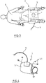
- Fig. 3 shows the first embodiment of the device according to the invention for making contact between the measuring means 4 and measuring device 1 figuratively.
- the measuring device 1 is not an integral part of the mat 5 according to the invention, but the measuring device 1 is arranged externally.
- the measuring device (not shown) is connected by a line 6 to the mat 5.
- the rolled or folded mat 5 can for example be attached to the housing of the measuring device 1 and thus supports the space-saving transport, without the lines 2, 3 can tangle, knot or twist.
- Fig. 4 schematically shows the first embodiment of the inventive device for making contact 7 between the measuring means 4 and measuring device 1 in a collapsed state by rolling.
- the mat 5 may also be folded by folding. The mat 5 is thus formed so that they roll through as in Fig. 4 , represented or folded by folding (not shown) is collapsible.
- the mat 5 according to the invention is furthermore designed such that the external line sections 3 are received within the folded mat 5 and secured against falling out.
- Fig. 5 shows the subject S, with his hands 10, 11 in the area of the mat 5 arranged electrodes 12, 13 takes. In any case, the electrodes 12, 13 partially form the measuring means 4.
- cables are typically arranged which connect electrodes positioned in the region of the arms 16, 17 with the measuring means 3 arranged in the area of the mat 5.
- the electrodes positioned in the region of the arms 16, 17 can be designed as adhesive electrodes.
- the electrodes 12, 13 are arranged adjacent to a first edge of the mat 5.
- the arms 16, 17 preferably extend from a second edge opposite the first edge of the mat 5.
- the in Fig. 5 illustrated arrangement of the electrodes 12, 13 and the boom 16, 17 reversed.
- the feet 14, 15 are placed on special electrodes arranged on the mat 5 and that the hands 10, 11 are electrically contacted via the arms 16, 17.
- electrodes provided in the mat 5 both for the hands 10, 11 and for the feet 14, 15.
- a variable size extent of the mat 5 proves to be expedient in such an embodiment.
- an essential design feature is that the mat 5 leads cables to different body locations of the subject S. In particular, more than one cable is thus routed. To adapt to the intended application, the mat 5 has a convenient length and width.
- the measuring device 1 is designed as a device for detecting and evaluating an at least regional substance composition of the body of the subject.
- a concretization of the subject S as a human or patient is particularly preferred to an application in a BCA (Body Composition Analizer).
- BCA Body Composition Analizer
- an analysis is carried out, which parts by weight of the human body z. B. has fat, muscle mass and bone mass.
- the evaluation can also refer to a variety of other or additional parameters.
- the mat 5 has at least two corners. Preferably, it is at least three corners, typically four corners.
- the measuring means 4 can be fixed to the mat 5.
- Such an identifiability comprises any mechanical connection between the measuring means 4 and the mat 5 which is present at least for carrying out the measuring process.
- the term of the mat 5 used several times above comprises on the one hand soft and / or flexible and / or elastic materials.
- a rigid board-like or plate-like embodiment can be realized.
- an education of several interconnected each rigid segments is thought that can be folded and positioned above or below the subject.
- Such an embodiment may be implemented similarly to a tank chain.
- the mat 5 is provided with a display device.
- the display device can visualize, for example, a respective operating status.
- functional or operator errors via the display.
- a measuring device operation and / or a measurement result display (GUI) are also possible.
- indications of functional or operating errors can also be issued acoustically.
- An identification or selection of the positioning of the device 7 can for example be done automatically via a position detection. Alternatively, a corresponding marking or selection is also possible manually by pressing a button on the mat 5 or on the measuring device 1.
Landscapes
- Health & Medical Sciences (AREA)
- Life Sciences & Earth Sciences (AREA)
- Medical Informatics (AREA)
- Molecular Biology (AREA)
- Veterinary Medicine (AREA)
- Biophysics (AREA)
- Pathology (AREA)
- Engineering & Computer Science (AREA)
- Biomedical Technology (AREA)
- Heart & Thoracic Surgery (AREA)
- Public Health (AREA)
- Physics & Mathematics (AREA)
- Surgery (AREA)
- Animal Behavior & Ethology (AREA)
- General Health & Medical Sciences (AREA)
- Nuclear Medicine, Radiotherapy & Molecular Imaging (AREA)
- Radiology & Medical Imaging (AREA)
- Cardiology (AREA)
- Measurement And Recording Of Electrical Phenomena And Electrical Characteristics Of The Living Body (AREA)
- Measuring Pulse, Heart Rate, Blood Pressure Or Blood Flow (AREA)
- Measuring And Recording Apparatus For Diagnosis (AREA)
Description
- Die Erfindung betrifft eine Vorrichtung zur messtechnischen Kontaktherstellung zwischen einem Patienten und einem Messgerät, aufweisend wenigstens ein Messmittel zur Anbindung an den Patienten und wenigstens eine Leitung, an der das Messmittel festgelegt ist, wobei die Leitung derart ausgebildet ist, dass die durch das Messmittel erfassten Messgrößen an ein Messgerät leitbar sind sowie bei der eine Matte mit der wenigstens einen Leitung derart verbunden ist, dass wenigstens teilweise ein interner Leitungsabschnitt gebildet ist,
- Die Erfindung betrifft darüber hinaus ein Messsystem zur Messung von physiologischen Werten.
- Schließlich betrifft die Erfindung die Verwendung der Vorrichtung zur messtechnischen Kontaktherstellung zwischen einem Subjekt und einem Messgerät.
- Es ist bekannt, dass zur Messung von Körpereigenschaften und Körperfunktionen von Subjekten, z.B. menschlichen Personen oder Tieren, mobile oder stationäre Messgeräte eingesetzt werden. Bei den zu messenden Eigenschaften oder Funktionen handelt es sich häufig um Bio- bzw. Körperimpedanzen, Herzfunktionen, Nervenfunktionen oder Elektrokardiogrammen. Für diese Messungen ist es erforderlich, dass das Messgerät mit dem zu messenden Subjekt verbunden wird. Im Wesentlichen sind für die Verbindung zwei verschiedene Varianten bekannt.
- Zum einen kann das Messgerät Kontaktstellen, beispielsweise Griff- oder Standflächen aufweisen, mit deren Hilfe durch Berührung des Subjektes die erforderliche Verbindung hergestellt wird. Eine derartige Ausgestaltung des Kontaktes zwischen Subjekt und Messgerät zeigt beispielsweise die
DE 10 2010 023 122 A1 . Es handelt sich hierbei um eine Vorrichtung, die den Kontakt zwischen einem stehenden Subjekt und dem Messgerät herstellt. - Ausgangspunkt der Erfindung ist eine zweite bekannte Vorrichtung, welche eine Kontaktherstellung zwischen dem Messgerät und Subjekt durch eine oder mehrere Leitungen, die Schläuche oder Kabel sein können, realisiert. In der Regel sind die Leitungen jeweils endseitig mit dem Messgerät und über Messmittel, wie z.B. Elektroden, mit dem Subjekt verbunden. Die meisten Körperfunktionsmessungen erfordern mehrere Kontaktstellen am Subjekt, häufig an den Extremitäten wie Armen und Beinen und dort wiederum vielfach an Händen und oder Füßen. Dabei ist häufig jeder endseitigen Leitung genau eine Extremität zugewiesen. Das bedeutet, dass die mehreren Messstellen des Subjektes mit den jeweils zugeordneten Messmitteln und Leitungen korrekt angeschlossen werden müssen. Auch sind häufig für eine Messstelle am Subjekt zwei oder mehrere Leitungen erforderlich. Eine weitere Variante ist, dass sich eine Leitung in mehrere Teilleitungen aufteilt und endseitige Messmittel aufweist, die an dem Subjekt angebracht werden. Die Kontaktherstellung wird bei dieser Vorrichtung bevorzugt bei liegenden oder sitzenden Subjekten realisiert.
- Ein Schwachpunkt der bekannten Vorrichtung ist, dass mit der Kontaktherstellung des Patienten als eines der möglichen Subjekte ein äußerst unangenehmes Gefühl des "Verkabeltseins" entsteht. Mögliche Folgen können sein, dass der Patient die Messuntersuchung abbricht oder gar nicht erst in Erwägung zieht.
- Weiterhin ist nachteilig, dass die korrekte Zuordnung der an den Leitungen endseitig angebrachten Elektroden zu der jeweiligen Extremität nur durch optisch oder haptisch zu erfassende Positionierungsanweisungen an das Bedienpersonal realisiert werden kann. Es besteht die Gefahr, dass die Positionierung der Elektroden an der falschen Extremität, d.h. linke oder rechte Hand, linker oder rechter Fuß bzw. zwischen Händen und Füßen vorgenommen wird - insbesondere wenn das Bedienpersonal die Anweisung nicht oder falsch wahrnimmt
- Nachteilig an der bekannten Vorrichtung ist darüber hinaus, dass die Verstauung der Leitungen für den Transport oder die Lagerung nach Messungsende umständlich und langwierig ist. Auch besteht die latente Gefahr der Beschädigung. Eine im Stand der Technik bekannte Lösung des Beschädigungsproblems bei Verstauung besteht darin, dass die Leitungen durch eine Ummantelung vor Abknicken oder Verdrillen geschützt werden sollen. Die Ummantelung schützt jedoch nicht zuverlässig vor diesen Beschädigungen und verursacht eine Versteifung der Leitungen, was die Handhabung verschlechtert und die Bewegungsfreiheit des Subjektes nach Anlegen der mit den Leitungen verbundenen Messmittel einschränkt. Auch verhindert die Ummantelung der Leitungen durch die dadurch verursachte Vergrößerung des minimal möglichen Aufrollradius der Leitungen, dass diese mit kleinem Packmaß verstaut werden können. Ein weiterer Nachteil dieser bekannten Vorrichtung ist, dass die Leitungen zum verknoten, verdrehen oder verheddern neigen. Dadurch wird die Handhabung zusätzlich erschwert.
- Aus der
US 2010/137704 A1 ist bereits eine Vorrichtung zur messtechnischen Kontaktherstellung zwischen einem Patienten und einem Messgerät bekannt. Die Vorrichtung besitzt Messmittel und Leitungen. Ein Teil der Leitungen erstreckt sich in einer Messmatte. - Eine ähnliche Vorrichtung wird auch in der
US 2010/324433 A1 beschrieben. Eine weitere ähnliche Vorrichtung ist auch ist auch aus derEP 1627597 A1 bekannt. - Es ist Aufgabe der Erfindung, eine Vorrichtung der eingangs beschriebenen Art zu schaffen, die eine generelle Verbesserung der Handhabung und Transportsicherheit bietet und die die eingangs beschriebenen Nachteile vermindert.
- Diese Aufgabe wird gelöst dadurch, dass die Messmatte als Elektroden zur Durchführung einer Bioimpedanzmessung ausgebildet ist und dass mindestens eine Elektrode für jede Hand des Patienten und mindestens eine Elektrode für jeden Fuß des Patienten angeordnet ist.
- Der mit der Erfindung erzielte Vorteil besteht darin, dass durch die wenigstens teilweise Verbindung der Leitungen mit einer Matte das äußerst unangenehme Gefühl des "Verkabeltseins" reduziert oder verhindert wird. Die Zuordnungssicherheit der jeweiligen Messmittel zu den Extremitäten wird unterstützt dadurch, dass durch die Lage der Matte auf oder unter dem Subjekt das jeweils örtlich nächstgelegene Messmittel, z.B. eine Elektrode, verwendet wird. Die sichere Verstauung mit kleinem Packmaß wird durch die Eigenschaft der Matte, zusammenlegbar zu sein gefördert.
Weitere vorteilhafte Ausgestaltungen der Erfindung sind in den abhängigen Ansprüchen beschrieben. - Infolge der Verwendung einer vorzugsweise elastischen, jedenfalls aber zumindest zusammenlegbaren Matte, welche wenigstens teilweise die gemäß dem Stand der Technik bekannten Leitungen als Mittel zur Kontaktherstellung zwischen zu messendem Subjekt und Messgerät ergänzt, werden die vorteilhaften Wirkungen erzielt. Die Elektroden können auch als Handelektroden vorhanden sein.
- Erfindungsgemäß vermeidet die Anordnung der Elektroden auf der Matte das Aufkleben einzelner Elektroden auf die Haut des Patienten. Statt der Vielzahl von einzelnen zu jeder der Elektroden führenden Kabel wird nur ein gegebenenfalls aus mehreren Leitungen bestehendes Kabel zur Verbindung der Matte mit dem Messgerät verwendet.
- Zur Vermeidung von Leitungen zur Energieversorgung von Bauelementen auf der Matte kann die Matte mit einer Batterie oder einem wiederaufladbaren Akkumulator ausgestattet werden. Ein Aufladen des Akkumulators kann beispielsweise bei einer Aufbewahrung der Matte im Bereich einer dafür vorgesehenen Halterung erfolgen. Zusätzlich kann die Matte mit Bedienknöpfen und Einrichtungen zur Darstellung eines aktuellen Zustandes ausgestattet sein, z. B. Start, Stopp, niedriger Ladezustand.
- Bei einer geeigneten zusammenlegbaren Ausbildung der Matte können die Kabel gegen ein Herausfallen bei einem Transport und bei der Aufbewahrung gesichert sein.
- Die erfindungsgemäße Vorrichtung zur Messung von physiologischen Werten besteht in einer ersten Ausführungsform aus einer Matte, an welcher die Leitungen wenigstens teilweise festgelegt sind oder diese aufnimmt. An den Leitungen sind endseitig Messmittel festgelegt. Die Leitungen weisen einen internen Abschnitt auf, d.h. ein Leitungsabschnitt verläuft innerhalb der Matte oder ist an der Außenfläche der Matte festgelegt, und einen externen Abschnitt auf, d.h. es ist ein Leitungsabschnitt außerhalb der Matte.
- Im Fall des Leitungsverlaufes als internen Abschnitt innerhalb der Matte ist die Matte in ihrem innern als Hohlraum ausgebildet derart, dass der interne Leitungsabschnitt aufgenommen werden kann. Dies kann beispielsweise dadurch realisiert werden, dass die Matte aus zwei biegsamen plattenartigen bzw. flächigen Halbzeugen besteht, die an ihren jeweiligen Außenrändern miteinander verbunden sind.
- Bei der Verwendung eines aufschäumbaren oder gießfähigen Werkstoffes als Ausgangsmaterial für die Matte kann der interne Abschnitt der Leitung auch direkt in den Mattenwerkstoff eingebettet werden. In einer bevorzugten Ausführungsform können die Leitungen derart angeordnet sein, dass der Übergang vom internen zum externen Leitungsabschnitt in den Eckenbereichen einer viereckig oder rechteckig ausgebildeten Matte erfolgt. Eine weitere Leitung mit internem und oder externem Abschnitt kann vorhanden sein um die Vorrichtung mit dem Messgerät zu verbinden.
- In einer zweiten bevorzugten Ausführungsform substituiert die Matte die gemäß dem Stand der Technik verwendeten Leitungen vollständig, d.h. es liegen nur Leitungen mit internem Abschnitt vor. Wird die Erfindung in dieser Form ausgestaltet, sind die Messmittel direkter Bestandteil der Matte oder an der Matte festgelegt. Als Messmittel können zum Beispiel herkömmliche Klebeelektroden, Auflageelektroden, Elektrodengriffe, federgespannte Klemmelektroden oder Fußkontaktelektroden verwendet werden. Bei der Verwendung von Elektrodengriffen und Fußkontaktelektroden ist das zu messenden Subjekt aufgefordert, die entsprechenden Kontakte mit den Extremitäten durch Berührung herzustellen. Im Fall der Elektrodengriffe sind diese mit den Händen zu umfassen. Durch Auflegen der Füße auf die Fußkontaktelektroden wird die Verbindung mit diesen hergestellt. Im Fall der Verwendung von Klebeelektroden ist durch Aufkleben an Händen bzw. Füßen die Verbindung herzustellen.
- Es ist weiterhin möglich, dass das Messgerät extern, d.h. außerhalb und beabstandet zur Matte angeordnet oder auf der Matte festgelegt oder integraler Bestandteil innerhalb der Matte ist. Die internen Leitungsabschnitte können innerhalb der Matte in einem Punkt zusammenlaufen, der sich vorzugsweise mittig der Mattenfläche befindet.
- Die Matte kann auf ein sitzendes oder liegendes Subjekt aufgelegt werden. Auch kann die Matte als Unterlage für ein sitzendes oder liegendes Subjekt Verwendung finden. Wird die erfindungsgemäße Matte als Unterlage unter das Subjekt ausgestaltet oder verwendet reduziert sich das äußerst unangenehme Gefühl des "Verkabeltseins" zusätzlich, das Subjekt nimmt die Leitungsverbindung praktisch kaum noch war.
- Die erfindungsgemäße Vorrichtung unterstützt die sichere Zuordnung der Messmittel an die jeweilige Extremität. Auch bei beliebiger Ausgestaltung der Mattenform kann das Bedienpersonal die Matte relativ zum Subjekt derart positionieren, dass immer eine Messmitteleinrichtung der jeweiligen Extremität am nächsten ist. Somit ist einzig durch die Lage der Matte relativ zum zu messenden Subjekt eine Messmittelzuordnung realisiert. Die korrekte Lage der Matte relativ zum zu messenden Subjekt kann dem Bedienpersonal dadurch angezeigt werden, dass auf der Matte ein Richtungshinweis oder Positionieranweisung angebracht ist. Auch könnte die Körperkontur auf der Matte abgebildet sein, welche mit der Matte in Kontakt zu bringen ist. Ist die erfindungsgemäße Matte in der zweiten bevorzugten Ausführungsform und unter Verwendung von Elektrodengriffen und Fußkontaktelektroden realisiert, ergibt sich zum einen die korrekte Zuordnung der Messmittel zu Händen und Füßen durch die jeweiligen Elektrodengriffe bzw. Fußkontaktelektroden und die Links-rechts-Zuordnung durch die Ausrichtung der Matte bezüglich Vorderseite oder Rückseite.
- Um die sichere Verstauung mit kleinem Packmaß zu unterstützen ist die Matte derart ausgebildet, dass sie zusammenlegbar ist. Bei der Verwendung von Leitungen mit internem und externem Abschnitt ist die Matte derart zusammenlegbar, dass die externen Leitungsabschnitte innerhalb der zusammen gelegten Matte aufgenommen werden können und gegen herausfallen gesichert sind.
- Die Erfindung wird nachfolgend mit Bezug auf die Figuren erläutert. Im Einzelnen zeigen
- Fig. 1
- eine Vorrichtung zur Messung von physiologischen Werten gemäß dem Stand der Technik,
- Fig. 2
- die schematische Darstellung der Vorrichtung zur Messung von physiologischen Werten in einer ersten Ausführungsform,
- Fig. 3
- die Verwendung der Vorrichtung zur Messung von physiologischen Werten in einer ersten Ausführungsform,
- Fig. 4
- die schematische Darstellung der Vorrichtung zur Messung von physiologischen Werten besteht in einer ersten Ausführungsform in zusammengerolltem Zustand und
- Fig. 5
- die zweite Ausführungsform, in der die Matte 5 die gemäß dem Stand der Technik verwendeten Leitungen 3 vollständig substituiert - Messmittel direkt an der Matte festgelegt.
-
Fig. 1 zeigt eine Vorrichtung zur Messung von physiologischen Werten gemäß dem Stand der Technik. Das mobile Messgerät 1 ist mit den zu messenden Subjekt S durch mehrere Leitungen 3 und Messmittel 4 verbunden, d.h. die Kontaktherstellung zwischen Messgerät 1 und zu messenden Subjekt erfolgt durch Leitungen. Die Messmittel 4, die endseitig an den Leitungen angebracht sind, sind sowohl an den Händen als auch an den Füßen des Objektes festgelegt. Es ist ersichtlich, dass diese Art der Kontaktherstellung zwischen Subjekt S und Messgerät 1 das Gefühl des Verkabeltseins verstärkt, die Messmittelzuordnung zu der jeweiligen Extremität fehlerträchtig ist und die Leitungen verknoten oder verheddern können. Weiterhin ist im Stand der Technik bekannt, dass mehr oder auch weniger Leitungen 3, als die Anzahl wie inFig. 1 dargestellt Verwendung finden. -
Fig. 2 zeigt schematisch eine erste Ausführungsform der erfindungsgemäßen Vorrichtung 7 zur Kontaktherstellung zwischen Messmittel 3 und Messgerät 7. Sie besteht aus einer Matte 5, welche die Leitungen 2 zwischen den Messmittel 3 und dem Messgerät 1 wenigstens teilweise aufnimmt oder ergänzt. Die Matte 5 weist Leitungen 3 auf, an denen endseitig Messmittel 4 festgelegt sind. Die Leitungen 2, 3 weisen einen internen Abschnitt 2 auf, d.h. ein Leitungsabschnitt verläuft innerhalb der Matte 5 oder ist an der Außenfläche der Matte 5 festgelegt, und einen externen Abschnitt 3 auf, d.h. es ist ein Leitungsabschnitt außerhalb der Matte 5. - In
Fig. 2 ist eine erfindungsgemäße Ausführungsform dargestellt, die das Messgerät 1 beinhaltet. Das Messgerät 1 kann dabei in die Matte 5 integriert oder auf der Matte 5 aufgebracht sein. Anstelle der integrierten Bauweise kann das Messgerät 1 auch außerhalb der Matte 5 angeordnet sein. Die externen Leitungsabschnitte 3 können mit der Matte 5 fest verbunden sein oder abnehmbar festgelegt sein. Die Festlegung kann beispielsweise durch Druckknöpfe erfolgen. Dargestellt ist die Festlegung der externen Leitungsabschnitte 3 in den Eckenbereichen einer rechteckigen Matte 5. - Alternativ können die externen Leitungsabschnitte 3 auch an beliebiger Stelle festgelegt sein. Auch ist es möglich, die Matte 5 in einer anderen als der dargestellten rechteckigen Form auszubilden. Ist das Messgerät 1 integraler Bestandteil der Matte 5, kann es mit sich oder an einer beliebigen Stelle der Matte 5 angeordnet sein. Das Subjekt S ist durch die Messmittel 4, den jeweils externen Leitungsabschnitt 3 und den jeweils internen Leitungsabschnitt 2 mit dem Messgerät 1 verbunden.
-
Fig. 3 zeigt die erste Ausführungsform der erfindungsgemäßen Vorrichtung zur Kontaktherstellung zwischen Messmittel 4 und Messgerät 1 bildlich. Im Gegensatz zur schematischen Darstellung derFigur 2 ist hier das Messgerät 1 nicht integraler Bestandteil der erfindungsgemäßen Matte 5, sondern das Messgerät 1 ist extern angeordnet. Das Messgerät (nicht dargestellt) wird durch eine Leitung 6 mit der Matte 5 verbunden. Die zusammengerollte oder zusammengelegte Matte 5 kann zum Beispiel an das Gehäuse des Messgerätes 1 angehängt werden und unterstützt somit den platzsparenden Transport, ohne dass sich die Leitungen 2, 3 verheddern, verknoten oder verdrehen können. Durch die Festlegung der externen Leitungsabschnitte 3 an den jeweiligen Eckenbereichen der Matte 5 wird der Anwender bzw. die Bedienungsperson intuitiv angeleitet, an welche Extremität der jeweils nächstliegende externe Leitungsabschnitt 4 mit seinen endseitigen Messmittel 4 zu verbinden ist. -
Fig. 4 zeigt schematisch die erste Ausführungsform der erfindungsgemäßen Vorrichtung zur Kontaktherstellung 7 zwischen Messmittel 4 und Messgerät 1 in einem durch rollen zusammengelegten Zustand. Anstelle die Matte 5 zusammenzurollen um dadurch den zusammengelegten Zustand zu erreichen kann die Matte 5 auch durch Falten zusammengelegt sein. Die Matte 5 ist also derart ausgebildet, dass sie durch rollen wie inFig 4 . dargestellt oder durch falten (ohne Abbildung) zusammenlegbar ist. - In der Ausführungsvariante mit externen Leitungsabschnitten 3 und endseitig festgelegten Messmitteln 4 ist die erfindungsgemäße Matte 5 weiterhin derart ausgebildet, dass die externen Leitungsabschnitte 3 innerhalb der zusammengelegten Matte 5 aufgenommen und gegen herausfallen gesichert werden.
-
Fig. 5 zeigt das Subjekt S, das mit seinen Händen 10, 11 im Bereich der Matte 5 angeordnete Elektroden 12, 13 ergreift. Die Elektroden 12, 13 bilden hierbei jedenfalls teilweise die Messmittel 4 aus. - Zur Verbindung mit Füßen 14, 15 des Subjektes S sind an der Matte 5 Ausleger 16, 17 angeordnet. Im Bereich der Ausleger 16, 17 werden typischerweise Kabel angeordnet, die im Bereich der Ausleger 16, 17 positionierte Elektroden mit den im Bereich der Matte 5 angeordneten Messmitteln 3 verbinden. Die im Bereich der Ausleger 16, 17 positionierten Elektroden können als Klebeelektroden ausgebildet sein.
- Vorzugsweise sind die Elektroden 12, 13 benachbart zu einem ersten Rand der Matte 5 angeordnet. Die Ausleger 16, 17 erstrecken sich vorzugsweise ausgehend von einem dem ersten Rand der Matte 5 gegenüberliegenden zweiten Rand.
- Gemäß einer Ausführungsvariante wird die in
Fig. 5 veranschaulichte Anordnung der Elektroden 12, 13 und der Ausleger 16, 17 vertauscht. Dies bedeutet, dass bei der Ausführungsvariante die Füße 14, 15 auf spezielle an der Matte 5 angeordnete Elektroden aufgesetzt werden und dass über die Ausleger 16, 17 die Hände 10, 11 elektrisch kontaktiert werden. Grundsätzlich wäre es auch denkbar, sowohl für die Hände 10, 11 als auch für die Füße 14, 15 vorgesehene Elektroden in die Matte 5 einzuarbeiten. Zur Anpassung an unterschiedliche Körpergrößen des Subjektes 1 erweist sich bei einer derartigen Ausführungsform aber eine veränderliche Größenausdehnung der Matte 5 als zweckmäßig. - Im Hinblick auf die konstruktive Gestaltung der Matte 5 besteht ein wesentliches konstruktives Merkmal darin, dass die Matte 5 Kabel zu verschiedenen Körperstellen des Subjektes S führt. Es werden somit insbesondere mehr als ein Kabel geführt. Zur Anpassung an die vorgesehene Anwendung weist die Matte 5 eine zweckmäßige Länge und Breite auf.
- Gemäß einer bevorzugten Anwendung ist das Messgerät 1 als ein Gerät zur Erfassung und Auswertung einer mindestens bereichsweisen stofflichen Zusammensetzung des Körpers des Subjektes ausgebildet. Besonders bevorzugt ist bei einer Konkretisierung des Subjektes S als Mensch oder Patient an eine Anwendung bei einem BCA (Body Composition Analizer) gedacht. Mit Hilfe eines derartigen Gerätes erfolgt insbesondere eine Analyse, welche Gewichtsanteile der menschliche Körper z. B. an Fett, Muskelmasse sowie Knochenmasse besitzt. Die Auswertung kann sich aber auch auf eine Vielzahl anderer oder zusätzlicher Parameter beziehen.
- Typischerweise weist die Matte 5 wenigstens zwei Ecken auf. Bevorzugt handelt es sich um wenigstens drei Ecken, typischerweise um vier Ecken.
- Bei den bereits erläuterten Ausführungsbeispielen wurde teilweise definiert, dass das Messmittel 4 an der Matte 5 festlegbar ist. Eine derartige Festlegbarkeit umfasst jede zumindest für die Durchführung des Messvorganges vorliegende mechanische Verbindung zwischen dem Messmittel 4 und der Matte 5. Umfasst sind hiervon insbesondere dauerhafte Verklebungen oder Verpressungen oder eine lediglich zeitweise Verbindung über lösbare Verbindungselemente, beispielsweise Klettverschlüsse oder Steckkupplungen.
- Der vorstehend mehrfach benutzte Begriff der Matte 5 umfasst zum einen weiche und/oder flexible und/oder elastische Materialien. Alternativ ist aber auch eine starre brettartige oder plattenartige Ausführungsform realisierbar. Darüber hinaus ist auch an eine Ausbildung aus mehreren miteinander verbundenen jeweils starren Segmenten gedacht, die zusammengefaltet werden können und über oder unter dem Subjekt positioniert werden. Eine derartige Ausführungsform kann ähnlich zu einer Panzerkette realisiert sein.
- Alternativ zur Verwendung einer ein elektrisches Signal übertragenden Leitung 6 ist auch an die Verwendung von drahtlosen Verbindungen gedacht, beispielsweise die Verwendung einer Funkverbindung. Gemäß einer besonderen Ausführungsform ist die Matte 5 mit einer Anzeigeeinrichtung versehen. Die Anzeigeeinrichtung kann beispielsweise einen jeweiligen Betriebsstatus visualisieren. Darüber hinaus ist es möglich, über die Anzeige Funktions- oder Bedienfehler zu visualisieren. Auch eine Messgeräte-Bedienung und/oder eine Messergebnis-Anzeige (GUI) sind möglich. Hinsichtlich der Betriebssicherheit können Hinweise auf Funktions- oder Bedienfehler auch akustisch ausgegeben werden.
- Eine Kennzeichnung oder Auswahl der Positionierung der Vorrichtung 7 kann zum Beispiel automatisch über eine Positionserkennung erfolgen. Alternativ ist eine entsprechende Kennzeichnung oder Auswahl auch manuell durch einen Tastendruck an der Matte 5 oder am Messgerät 1 möglich.
Claims (19)
- Vorrichtung (7) zur messtechnischen Kontaktherstellung zwischen einem Patienten und einem Messgerät (1), aufweisend Messmittel (4) zur Anbindung an den Patienten und Leitungen (2, 3), an denen die Messmittel (4) festgelegt sind, wobei die Leitungen (2, 3) derart ausgebildet sind, dass die durch die Messmittel (4) erfassten Messgrößen an ein Messgerät (1) leitbar sind sowie bei der eine Matte (5) mit den Leitungen (2, 3) derart verbunden ist, dass wenigstens teilweise ein interner Leitungsabschnitt (2) gebildet ist, dadurch gekennzeichnet, dass die Messmittel als Elektroden (12, 13) zur Durchführung einer Bioimpedanzmessung ausgebildet sind und dass eine Elektrode (12, 13) für jede Hand (10, 11) des Patienten und eine Elektrode für jeden Fuß (14, 15) des Patienten in die Matte (5) eingearbeitet sind.
- Vorrichtung (7) nach Anspruch 1, dadurch gekennzeichnet, dass wenigstens ein interner Leitungsabschnitt (2) an einer Außenfläche der Matte (5) festlegbar ist.
- Vorrichtung (7) nach Anspruch 1, dadurch gekennzeichnet, dass wenigstens ein interner Leitungsabschnitt (2) innerhalb der Matte (5) angeordnet ist.
- Vorrichtung (7) nach Anspruch 1, dadurch gekennzeichnet, dass wenigstens ein interner Leitungsabschnitt (2) integraler Bestandteil der Matte (5) ist.
- Vorrichtung (7) nach einem der vorgehenden Ansprüche, dadurch gekennzeichnet, dass wenigstens ein externer Leitungsabschnitt (3) von dem internen Leitungsabschnitt (2) lösbar ist.
- Vorrichtung (7) nach einem der vorgehenden Ansprüche, dadurch gekennzeichnet, dass die Matte (5) wenigstens zwei Ecken aufweist, in deren Bereichen die externen Leitungsabschnitte (3) angeordnet sind.
- Vorrichtung (7) nach einem der vorgehenden Ansprüche, dadurch gekennzeichnet, dass wenigstens ein Messmittel (4) an der Matte (5) festlegbar ist.
- Vorrichtung (7) nach Anspruch 7, dadurch gekennzeichnet, dass wenigstens ein Messmittel (4) integraler oder lösbarer Bestandteil eines Abschnittes der Matte (5) ist.
- Vorrichtung (7) nach einem der Ansprüche 6 bis 8, dadurch gekennzeichnet, dass das wenigstens eine Messmittel (4) in einem Eckenbereichsabschnitt der Matte (5) angeordnet ist
- Vorrichtung (7) nach Anspruch 1, dadurch gekennzeichnet, dass die Matte (5) durch Rollen oder Falten zusammenlegbar ist.
- Vorrichtung (7) nach Anspruch 10, dadurch gekennzeichnet, dass die Matte (5) derart zusammenlegbar ist, dass die externen Leitungsabschnitte (3, 4) in der zusammengelegten Matte angeordnet und gegen Herausfallen gesichert sind.
- Vorrichtung (7) nach einem der vorgehenden Ansprüche, dadurch gekennzeichnet, dass die Matte (5) eine integrierte Energieversorgung, vorzugsweise eine Stromversorgung durch eine Batterie oder einen Akkumulator aufweist.
- Vorrichtung (7) nach einem der vorgehenden Ansprüche, dadurch gekennzeichnet, dass ein Messgerät (1) integraler Bestandteil der Matte (5) ist.
- Vorrichtung (7) nach einem der Ansprüche 1 bis 12, dadurch gekennzeichnet, dass ein Messgerät (1) an der Oberfläche der Matte (5) festlegbar ist.
- Vorrichtung (7) nach einem der Ansprüche 1 bis 12 gekennzeichnet durch eine Matte (5) aufweisend Anschlussmittel (6) geeignet zum Anschluss eines von der Matte (5) beabstandeten Messgerätes (1).
- Vorrichtung (7) nach einem der vorgehenden Ansprüche, dadurch gekennzeichnet, dass die Elektroden durch Klebeelektroden oder Handgriffelektroden oder Fußkontaktelektroden oder federgespannte Klemmelektroden gebildet sind.
- Verwendung der Vorrichtung (7) nach einem der vorgehenden Ansprüche durch Auflegen auf oder Unterlegen unter den zu messenden Patienten.
- Messsystem zur Messung von Bioimpedanz aufweisend eine Vorrichtung (7) nach einem der Ansprüche 1 bis 16.
- Vorrichtung nach einem der Ansprüche 1 bis 16, dadurch gekennzeichnet, das eine Bedienung und/oder eine Anzeige eines externen oder in die Matte integrierten Messgerätes an/durch die Matte erfolgt.
Priority Applications (1)
| Application Number | Priority Date | Filing Date | Title |
|---|---|---|---|
| PL14841420T PL3041404T3 (pl) | 2013-09-05 | 2014-09-03 | Urządzenie do mierzenia wartości fizjologicznych |
Applications Claiming Priority (2)
| Application Number | Priority Date | Filing Date | Title |
|---|---|---|---|
| DE201310014982 DE102013014982A1 (de) | 2013-09-05 | 2013-09-05 | Vorrichtung zur Messung von physiologischen Werten |
| PCT/IB2014/002093 WO2015044767A2 (de) | 2013-09-05 | 2014-09-03 | Vorrichtung zur messung von physiologischen werten |
Publications (2)
| Publication Number | Publication Date |
|---|---|
| EP3041404A2 EP3041404A2 (de) | 2016-07-13 |
| EP3041404B1 true EP3041404B1 (de) | 2017-08-23 |
Family
ID=52470086
Family Applications (1)
| Application Number | Title | Priority Date | Filing Date |
|---|---|---|---|
| EP14841420.4A Active EP3041404B1 (de) | 2013-09-05 | 2014-09-03 | Vorrichtung zur messung von physiologischen werten |
Country Status (6)
| Country | Link |
|---|---|
| US (1) | US10264991B2 (de) |
| EP (1) | EP3041404B1 (de) |
| DE (1) | DE102013014982A1 (de) |
| ES (1) | ES2642539T3 (de) |
| PL (1) | PL3041404T3 (de) |
| WO (1) | WO2015044767A2 (de) |
Families Citing this family (2)
| Publication number | Priority date | Publication date | Assignee | Title |
|---|---|---|---|---|
| TWI723696B (zh) * | 2019-12-20 | 2021-04-01 | 金上達科技股份有限公司 | 人體生物訊息檢測裝置及其方法 |
| AT526119A1 (de) * | 2022-05-03 | 2023-11-15 | Skrabal Dr Falko | Diagnosesystem |
Family Cites Families (16)
| Publication number | Priority date | Publication date | Assignee | Title |
|---|---|---|---|---|
| US3476104A (en) * | 1967-08-08 | 1969-11-04 | James B Davis | Fixed dorsal electrode system for electrocardiography |
| US4121573A (en) * | 1973-10-04 | 1978-10-24 | Goebel Fixture Co. | Wireless cardiac monitoring system and electrode-transmitter therefor |
| US5224479A (en) * | 1991-06-21 | 1993-07-06 | Topy Enterprises Limited | ECG diagnostic pad |
| DE10001698A1 (de) * | 1999-10-19 | 2001-04-26 | Thomas Hilfen Hilbeg Gmbh & Co | Vorrichtung und Verfahren zum Messen von Werten einer liegenden Person sowie Drucksensor |
| US6721977B2 (en) * | 2001-08-03 | 2004-04-20 | Angela Solesbee | Medical procedure table pad |
| US20060173367A1 (en) * | 2003-03-27 | 2006-08-03 | Equitronic Technologies Pty Ltd | Equine fitness monitoring |
| US20060041196A1 (en) | 2004-08-17 | 2006-02-23 | Quasar, Inc. | Unobtrusive measurement system for bioelectric signals |
| US20070197925A1 (en) * | 2006-02-17 | 2007-08-23 | Moore Kenneth S | Acquisition of multiple-lead electrocardiogram |
| US8491473B2 (en) * | 2007-02-08 | 2013-07-23 | Acist Medical Systems, Inc. | Medical procedure mat and draping system |
| US20100137704A1 (en) * | 2008-12-02 | 2010-06-03 | Surgivision, Inc. | Medical mats with electrical paths and methods for using the same |
| DE102009039257A1 (de) * | 2009-08-28 | 2011-03-10 | Up Management Gmbh | Blutdruckmessvorrichtung und Verfahren zur Blutdruckmessung eines Lebewesens |
| DE102010023122A1 (de) | 2010-06-01 | 2011-12-01 | Seca Ag | Vorrichtung zur Messung von Bioimpedanzen |
| JP5625576B2 (ja) * | 2010-07-22 | 2014-11-19 | オムロンヘルスケア株式会社 | 脂肪量測定装置 |
| US9332919B2 (en) * | 2011-04-04 | 2016-05-10 | Cardiocity Limited | Heart monitoring apparatus |
| EP2614769A1 (de) * | 2012-01-10 | 2013-07-17 | Koninklijke Philips Electronics N.V. | Elektrokardiograf-Sensormatte |
| DE102014107718B3 (de) * | 2014-06-02 | 2015-04-02 | Seca Ag | Aufnahmevorrichtung für die elektrische Impedanzanalyse |
-
2013
- 2013-09-05 DE DE201310014982 patent/DE102013014982A1/de not_active Withdrawn
-
2014
- 2014-09-03 EP EP14841420.4A patent/EP3041404B1/de active Active
- 2014-09-03 US US15/034,621 patent/US10264991B2/en active Active
- 2014-09-03 WO PCT/IB2014/002093 patent/WO2015044767A2/de not_active Ceased
- 2014-09-03 ES ES14841420.4T patent/ES2642539T3/es active Active
- 2014-09-03 PL PL14841420T patent/PL3041404T3/pl unknown
Non-Patent Citations (1)
| Title |
|---|
| None * |
Also Published As
| Publication number | Publication date |
|---|---|
| WO2015044767A3 (de) | 2015-08-13 |
| ES2642539T3 (es) | 2017-11-16 |
| US20160278707A1 (en) | 2016-09-29 |
| PL3041404T3 (pl) | 2018-01-31 |
| US10264991B2 (en) | 2019-04-23 |
| WO2015044767A2 (de) | 2015-04-02 |
| EP3041404A2 (de) | 2016-07-13 |
| DE102013014982A1 (de) | 2015-03-05 |
Similar Documents
| Publication | Publication Date | Title |
|---|---|---|
| DE112011101047B4 (de) | Körperfettmessvorrichtung | |
| DE69535411T2 (de) | Impedanzmessgerät zum Gebrauch als Instrument zur Überwachung des Gesundheitszustandes | |
| DE112008001906B4 (de) | Körperbefestigungseinheit zur Messung einer bioelektrischen Impedanz und Körperfettmessvorrichtung | |
| DE102008030534A1 (de) | Vorrichtung zum Bestimmen der Stabilität eines Kniegelenks | |
| DE102014107718B3 (de) | Aufnahmevorrichtung für die elektrische Impedanzanalyse | |
| EP2308372A1 (de) | Bioimpedanzmessvorrichtung | |
| DE112008001483T5 (de) | Körperfettmessvorrichtung | |
| DE112011101045B4 (de) | Körperfettmessvorrichtung | |
| DE112008001501T5 (de) | Körperbefestigungseinheit zur Messung einer bioelektrischen Impedanz und Körperfettmessvorrichtung | |
| EP2305111A1 (de) | Bioimpedanzmessvorrichtung und -verfahren | |
| DE112008000629T5 (de) | Messvorrichtung zur Messung des Viszeralfettes | |
| DE112011101048B4 (de) | Körperfettmessvorrichtung | |
| DE102008039844A1 (de) | Tastkopf mit wenigstens zwei Elektroden zur Impedanzmessung, Anordnung und Verfahren hierzu | |
| AT515976B1 (de) | Vorrichtung zum Erfassen von Tremor | |
| EP3048967B1 (de) | Verfahren und vorrichtung zur bioelektrischen impedanz-messung (bia) des körpers einer person | |
| DE102013014982A1 (de) | Vorrichtung zur Messung von physiologischen Werten | |
| DE102008049287A1 (de) | EKG-System sowie Verfahren | |
| DE60209933T2 (de) | Dynamometer und zugehöriges auswertungsverfahren | |
| DE102016215936A1 (de) | Brustgurt zur Aufnahme eines Elektrokardiogramms | |
| EP2863794A1 (de) | Verfahren und gerät zur ermittlung von körperzusammensetzungs-parametern mit bioimpedanzmessung | |
| WO2013013962A1 (de) | Saugeinheit und elektrodenleitung für ein ekg-gerät | |
| DE102013022145A1 (de) | Verfahren und Vorrichtung zu bioelektrischen Impedanz-Messung (BIA) des Körpers einer Person | |
| DE102011122572A1 (de) | Kontrollgerät zur Kontrolle von Körperfehlhaltungen | |
| DE102010053413B4 (de) | Isoliereinrichtung, Set, Behandlungsvorrichtung sowie Verfahren | |
| DE202013104614U1 (de) | Sensorik zur Lageerfassung der Finger- und Zehenglieder |
Legal Events
| Date | Code | Title | Description |
|---|---|---|---|
| PUAI | Public reference made under article 153(3) epc to a published international application that has entered the european phase |
Free format text: ORIGINAL CODE: 0009012 |
|
| 17P | Request for examination filed |
Effective date: 20160331 |
|
| AK | Designated contracting states |
Kind code of ref document: A2 Designated state(s): AL AT BE BG CH CY CZ DE DK EE ES FI FR GB GR HR HU IE IS IT LI LT LU LV MC MK MT NL NO PL PT RO RS SE SI SK SM TR |
|
| AX | Request for extension of the european patent |
Extension state: BA ME |
|
| DAX | Request for extension of the european patent (deleted) | ||
| GRAP | Despatch of communication of intention to grant a patent |
Free format text: ORIGINAL CODE: EPIDOSNIGR1 |
|
| INTG | Intention to grant announced |
Effective date: 20170407 |
|
| GRAS | Grant fee paid |
Free format text: ORIGINAL CODE: EPIDOSNIGR3 |
|
| GRAA | (expected) grant |
Free format text: ORIGINAL CODE: 0009210 |
|
| AK | Designated contracting states |
Kind code of ref document: B1 Designated state(s): AL AT BE BG CH CY CZ DE DK EE ES FI FR GB GR HR HU IE IS IT LI LT LU LV MC MK MT NL NO PL PT RO RS SE SI SK SM TR |
|
| REG | Reference to a national code |
Ref country code: GB Ref legal event code: FG4D Free format text: NOT ENGLISH |
|
| REG | Reference to a national code |
Ref country code: CH Ref legal event code: EP |
|
| REG | Reference to a national code |
Ref country code: AT Ref legal event code: REF Ref document number: 920401 Country of ref document: AT Kind code of ref document: T Effective date: 20170915 |
|
| REG | Reference to a national code |
Ref country code: IE Ref legal event code: FG4D Free format text: LANGUAGE OF EP DOCUMENT: GERMAN |
|
| REG | Reference to a national code |
Ref country code: FR Ref legal event code: PLFP Year of fee payment: 4 |
|
| REG | Reference to a national code |
Ref country code: DE Ref legal event code: R096 Ref document number: 502014005194 Country of ref document: DE |
|
| REG | Reference to a national code |
Ref country code: ES Ref legal event code: FG2A Ref document number: 2642539 Country of ref document: ES Kind code of ref document: T3 Effective date: 20171116 |
|
| REG | Reference to a national code |
Ref country code: NL Ref legal event code: MP Effective date: 20170823 |
|
| REG | Reference to a national code |
Ref country code: LT Ref legal event code: MG4D |
|
| PG25 | Lapsed in a contracting state [announced via postgrant information from national office to epo] |
Ref country code: NL Free format text: LAPSE BECAUSE OF FAILURE TO SUBMIT A TRANSLATION OF THE DESCRIPTION OR TO PAY THE FEE WITHIN THE PRESCRIBED TIME-LIMIT Effective date: 20170823 Ref country code: FI Free format text: LAPSE BECAUSE OF FAILURE TO SUBMIT A TRANSLATION OF THE DESCRIPTION OR TO PAY THE FEE WITHIN THE PRESCRIBED TIME-LIMIT Effective date: 20170823 Ref country code: SE Free format text: LAPSE BECAUSE OF FAILURE TO SUBMIT A TRANSLATION OF THE DESCRIPTION OR TO PAY THE FEE WITHIN THE PRESCRIBED TIME-LIMIT Effective date: 20170823 Ref country code: NO Free format text: LAPSE BECAUSE OF FAILURE TO SUBMIT A TRANSLATION OF THE DESCRIPTION OR TO PAY THE FEE WITHIN THE PRESCRIBED TIME-LIMIT Effective date: 20171123 Ref country code: LT Free format text: LAPSE BECAUSE OF FAILURE TO SUBMIT A TRANSLATION OF THE DESCRIPTION OR TO PAY THE FEE WITHIN THE PRESCRIBED TIME-LIMIT Effective date: 20170823 Ref country code: HR Free format text: LAPSE BECAUSE OF FAILURE TO SUBMIT A TRANSLATION OF THE DESCRIPTION OR TO PAY THE FEE WITHIN THE PRESCRIBED TIME-LIMIT Effective date: 20170823 |
|
| PG25 | Lapsed in a contracting state [announced via postgrant information from national office to epo] |
Ref country code: RS Free format text: LAPSE BECAUSE OF FAILURE TO SUBMIT A TRANSLATION OF THE DESCRIPTION OR TO PAY THE FEE WITHIN THE PRESCRIBED TIME-LIMIT Effective date: 20170823 Ref country code: IS Free format text: LAPSE BECAUSE OF FAILURE TO SUBMIT A TRANSLATION OF THE DESCRIPTION OR TO PAY THE FEE WITHIN THE PRESCRIBED TIME-LIMIT Effective date: 20171223 Ref country code: GR Free format text: LAPSE BECAUSE OF FAILURE TO SUBMIT A TRANSLATION OF THE DESCRIPTION OR TO PAY THE FEE WITHIN THE PRESCRIBED TIME-LIMIT Effective date: 20171124 Ref country code: BG Free format text: LAPSE BECAUSE OF FAILURE TO SUBMIT A TRANSLATION OF THE DESCRIPTION OR TO PAY THE FEE WITHIN THE PRESCRIBED TIME-LIMIT Effective date: 20171123 Ref country code: LV Free format text: LAPSE BECAUSE OF FAILURE TO SUBMIT A TRANSLATION OF THE DESCRIPTION OR TO PAY THE FEE WITHIN THE PRESCRIBED TIME-LIMIT Effective date: 20170823 |
|
| PG25 | Lapsed in a contracting state [announced via postgrant information from national office to epo] |
Ref country code: CZ Free format text: LAPSE BECAUSE OF FAILURE TO SUBMIT A TRANSLATION OF THE DESCRIPTION OR TO PAY THE FEE WITHIN THE PRESCRIBED TIME-LIMIT Effective date: 20170823 Ref country code: RO Free format text: LAPSE BECAUSE OF FAILURE TO SUBMIT A TRANSLATION OF THE DESCRIPTION OR TO PAY THE FEE WITHIN THE PRESCRIBED TIME-LIMIT Effective date: 20170823 Ref country code: DK Free format text: LAPSE BECAUSE OF FAILURE TO SUBMIT A TRANSLATION OF THE DESCRIPTION OR TO PAY THE FEE WITHIN THE PRESCRIBED TIME-LIMIT Effective date: 20170823 |
|
| REG | Reference to a national code |
Ref country code: DE Ref legal event code: R097 Ref document number: 502014005194 Country of ref document: DE |
|
| PG25 | Lapsed in a contracting state [announced via postgrant information from national office to epo] |
Ref country code: MC Free format text: LAPSE BECAUSE OF FAILURE TO SUBMIT A TRANSLATION OF THE DESCRIPTION OR TO PAY THE FEE WITHIN THE PRESCRIBED TIME-LIMIT Effective date: 20170823 Ref country code: SK Free format text: LAPSE BECAUSE OF FAILURE TO SUBMIT A TRANSLATION OF THE DESCRIPTION OR TO PAY THE FEE WITHIN THE PRESCRIBED TIME-LIMIT Effective date: 20170823 Ref country code: EE Free format text: LAPSE BECAUSE OF FAILURE TO SUBMIT A TRANSLATION OF THE DESCRIPTION OR TO PAY THE FEE WITHIN THE PRESCRIBED TIME-LIMIT Effective date: 20170823 Ref country code: SM Free format text: LAPSE BECAUSE OF FAILURE TO SUBMIT A TRANSLATION OF THE DESCRIPTION OR TO PAY THE FEE WITHIN THE PRESCRIBED TIME-LIMIT Effective date: 20170823 |
|
| REG | Reference to a national code |
Ref country code: IE Ref legal event code: MM4A |
|
| REG | Reference to a national code |
Ref country code: BE Ref legal event code: MM Effective date: 20170930 |
|
| PG25 | Lapsed in a contracting state [announced via postgrant information from national office to epo] |
Ref country code: LU Free format text: LAPSE BECAUSE OF NON-PAYMENT OF DUE FEES Effective date: 20170903 |
|
| PLBE | No opposition filed within time limit |
Free format text: ORIGINAL CODE: 0009261 |
|
| STAA | Information on the status of an ep patent application or granted ep patent |
Free format text: STATUS: NO OPPOSITION FILED WITHIN TIME LIMIT |
|
| PG25 | Lapsed in a contracting state [announced via postgrant information from national office to epo] |
Ref country code: IE Free format text: LAPSE BECAUSE OF NON-PAYMENT OF DUE FEES Effective date: 20170903 |
|
| 26N | No opposition filed |
Effective date: 20180524 |
|
| PG25 | Lapsed in a contracting state [announced via postgrant information from national office to epo] |
Ref country code: SI Free format text: LAPSE BECAUSE OF FAILURE TO SUBMIT A TRANSLATION OF THE DESCRIPTION OR TO PAY THE FEE WITHIN THE PRESCRIBED TIME-LIMIT Effective date: 20170823 Ref country code: BE Free format text: LAPSE BECAUSE OF NON-PAYMENT OF DUE FEES Effective date: 20170930 |
|
| REG | Reference to a national code |
Ref country code: FR Ref legal event code: PLFP Year of fee payment: 5 |
|
| PG25 | Lapsed in a contracting state [announced via postgrant information from national office to epo] |
Ref country code: MT Free format text: LAPSE BECAUSE OF FAILURE TO SUBMIT A TRANSLATION OF THE DESCRIPTION OR TO PAY THE FEE WITHIN THE PRESCRIBED TIME-LIMIT Effective date: 20170823 |
|
| PG25 | Lapsed in a contracting state [announced via postgrant information from national office to epo] |
Ref country code: HU Free format text: LAPSE BECAUSE OF FAILURE TO SUBMIT A TRANSLATION OF THE DESCRIPTION OR TO PAY THE FEE WITHIN THE PRESCRIBED TIME-LIMIT; INVALID AB INITIO Effective date: 20140903 |
|
| PG25 | Lapsed in a contracting state [announced via postgrant information from national office to epo] |
Ref country code: CY Free format text: LAPSE BECAUSE OF FAILURE TO SUBMIT A TRANSLATION OF THE DESCRIPTION OR TO PAY THE FEE WITHIN THE PRESCRIBED TIME-LIMIT Effective date: 20170823 |
|
| PG25 | Lapsed in a contracting state [announced via postgrant information from national office to epo] |
Ref country code: MK Free format text: LAPSE BECAUSE OF FAILURE TO SUBMIT A TRANSLATION OF THE DESCRIPTION OR TO PAY THE FEE WITHIN THE PRESCRIBED TIME-LIMIT Effective date: 20170823 |
|
| PG25 | Lapsed in a contracting state [announced via postgrant information from national office to epo] |
Ref country code: TR Free format text: LAPSE BECAUSE OF FAILURE TO SUBMIT A TRANSLATION OF THE DESCRIPTION OR TO PAY THE FEE WITHIN THE PRESCRIBED TIME-LIMIT Effective date: 20170823 |
|
| PG25 | Lapsed in a contracting state [announced via postgrant information from national office to epo] |
Ref country code: PT Free format text: LAPSE BECAUSE OF FAILURE TO SUBMIT A TRANSLATION OF THE DESCRIPTION OR TO PAY THE FEE WITHIN THE PRESCRIBED TIME-LIMIT Effective date: 20170823 |
|
| PG25 | Lapsed in a contracting state [announced via postgrant information from national office to epo] |
Ref country code: AL Free format text: LAPSE BECAUSE OF FAILURE TO SUBMIT A TRANSLATION OF THE DESCRIPTION OR TO PAY THE FEE WITHIN THE PRESCRIBED TIME-LIMIT Effective date: 20170823 |
|
| REG | Reference to a national code |
Ref country code: AT Ref legal event code: MM01 Ref document number: 920401 Country of ref document: AT Kind code of ref document: T Effective date: 20190903 |
|
| PG25 | Lapsed in a contracting state [announced via postgrant information from national office to epo] |
Ref country code: AT Free format text: LAPSE BECAUSE OF NON-PAYMENT OF DUE FEES Effective date: 20190903 |
|
| PGFP | Annual fee paid to national office [announced via postgrant information from national office to epo] |
Ref country code: PL Payment date: 20220825 Year of fee payment: 9 |
|
| PGFP | Annual fee paid to national office [announced via postgrant information from national office to epo] |
Ref country code: IT Payment date: 20240924 Year of fee payment: 11 |
|
| PG25 | Lapsed in a contracting state [announced via postgrant information from national office to epo] |
Ref country code: PL Free format text: LAPSE BECAUSE OF NON-PAYMENT OF DUE FEES Effective date: 20230903 |
|
| REG | Reference to a national code |
Ref country code: DE Ref legal event code: R082 Ref document number: 502014005194 Country of ref document: DE Representative=s name: PATENTANWAELTE KLICKOW & WETZEL PARTGMBB, DE |
|
| REG | Reference to a national code |
Ref country code: CH Ref legal event code: U11 Free format text: ST27 STATUS EVENT CODE: U-0-0-U10-U11 (AS PROVIDED BY THE NATIONAL OFFICE) Effective date: 20251001 |
|
| PGFP | Annual fee paid to national office [announced via postgrant information from national office to epo] |
Ref country code: DE Payment date: 20250919 Year of fee payment: 12 |
|
| PGFP | Annual fee paid to national office [announced via postgrant information from national office to epo] |
Ref country code: GB Payment date: 20250919 Year of fee payment: 12 |
|
| PGFP | Annual fee paid to national office [announced via postgrant information from national office to epo] |
Ref country code: FR Payment date: 20250922 Year of fee payment: 12 |
|
| PGFP | Annual fee paid to national office [announced via postgrant information from national office to epo] |
Ref country code: CH Payment date: 20251001 Year of fee payment: 12 |
|
| PGFP | Annual fee paid to national office [announced via postgrant information from national office to epo] |
Ref country code: ES Payment date: 20251028 Year of fee payment: 12 |