EP3041395B1 - Verbindungsvorrichtung - Google Patents
Verbindungsvorrichtung Download PDFInfo
- Publication number
- EP3041395B1 EP3041395B1 EP14756012.2A EP14756012A EP3041395B1 EP 3041395 B1 EP3041395 B1 EP 3041395B1 EP 14756012 A EP14756012 A EP 14756012A EP 3041395 B1 EP3041395 B1 EP 3041395B1
- Authority
- EP
- European Patent Office
- Prior art keywords
- locking element
- component
- connecting device
- locking
- accordance
- Prior art date
- Legal status (The legal status is an assumption and is not a legal conclusion. Google has not performed a legal analysis and makes no representation as to the accuracy of the status listed.)
- Active
Links
Images




Classifications
-
- A—HUMAN NECESSITIES
- A47—FURNITURE; DOMESTIC ARTICLES OR APPLIANCES; COFFEE MILLS; SPICE MILLS; SUCTION CLEANERS IN GENERAL
- A47L—DOMESTIC WASHING OR CLEANING; SUCTION CLEANERS IN GENERAL
- A47L9/00—Details or accessories of suction cleaners, e.g. mechanical means for controlling the suction or for effecting pulsating action; Storing devices specially adapted to suction cleaners or parts thereof; Carrying-vehicles specially adapted for suction cleaners
- A47L9/24—Hoses or pipes; Hose or pipe couplings
- A47L9/242—Hose or pipe couplings
Definitions
- the present invention relates to a connecting device for connecting two components.
- a connection device can be used, for example, for detachably fixing a hose of a suction device to the suction device and / or to a machine tool to be connected by means of the hose to the suction device.
- the DE 28 29 938 A1 , the FR 2 846 069 A1 , the EP 0 629 806 A2 , the DE 10 2004 038 630 A1 and the EP 1 832 220 A2 disclose various embodiments of connectors and couplings for connecting two components.
- the present invention has for its object to provide a connecting device which is particularly easy and comfortable to handle by a user.
- a connecting device which comprises a first component, a releasably connectable to the first component second component and a locking element which receivable in a receiving portion of the first component and for locking a connection between the first component and the second component a receiving opening of the second component is engageable, wherein the locking element for unlocking the connection is actuated by a user, wherein the receiving opening adjoins an insertion of the second component, through which the locking element for connecting the components together and / or for releasing the Components can be passed through each other, and wherein the locking element during the passage of the locking element through the insertion section accessible to the user, in particular by the user operable is.
- the locking element can be passed through an insertion and thereby accessible to the user, the user can handle the connecting device particularly simple and comfortable.
- the user may preferably engage directly on the locking element, in particular during the passage of the locking element through the insertion section.
- the locking element for unlocking the connection by applying a compressive force with the receiving opening can be disengaged.
- the locking element can be touched by the user during the passage of the locking element through the insertion section, in particular in order to exert a compressive force on the locking element.
- the locking element extends in a locked state, preferably by a length in the receiving opening or through the receiving opening, which is greater than a distance about which the locking element is movable to be brought from the locked state to an unlocked state in which the locking element for removing the components can be guided from one another through the insertion section.
- the locking element comprises a locking portion, by means of which the locking element engages behind the receiving opening in a locked state of the locking element with respect to a connecting direction.
- the locking element comprises an actuating portion on which a user for actuating the locking element, in particular directly engages.
- the locking element comprises a web section, by means of which the locking element can be guided through the insertion section.
- the web section is arranged between the locking section and the actuating section.
- the connecting device preferably comprises a closed or open connecting ring, on which preferably one or more locking elements are arranged or which comprises one or more locking elements.
- connecting ring and the one or more locking elements are integrally formed with each other.
- the connecting device comprises a one-piece injection-molded component, by means of which the connecting ring and the one or more locking elements are formed or which comprises the connecting ring and the one or more locking elements.
- the one locking element or the plurality of locking elements project outwardly in a substantially radial direction with respect to an axis of symmetry of the connecting ring, in particular protrude away from the connecting ring to the outside.
- a locking portion of a locking element is arranged on the connecting ring. In the radial outward direction, preferably adjoins a web portion of the locking element. An actuating section of the locking element preferably adjoins the web section in the radial direction.
- the connecting device In the assembled state, in particular in the locked and / or unlocked state, the connecting device preferably protrudes Operating portion of the locking element always in the radial direction outwardly beyond the receiving opening addition.
- the locking element and / or the connecting ring is preferably elastically deformable and / or flexible, in particular resilient, formed and / or arranged.
- the connecting device comprises two or more locking elements, which are arranged on opposite sides of the connecting ring with respect to an axis of symmetry of the connecting ring.
- a user actuates two such locking elements simultaneously in order to separate components initially present in the locked state. The user can attack this particular with a thumb and a forefinger or middle finger of the same hand on the two locking elements.
- the connecting ring is preferably designed to lock and / or unlock the connection between the two components elastically and / or deformable by actuation of the one locking element or the plurality of locking elements, in particular resilient and / or reversible.
- the receiving portion of the first component is formed as a substantially annular receiving groove, in which in particular the connecting ring can be arranged or arranged.
- the insertion section preferably comprises at least one insertion bevel or has at least one insertion bevel, by means of which the locking element can be fed when connecting the components to a constriction of the insertion section.
- the locking element must be passed through the constriction to enter the receiving opening and bring the components in the locked state.
- the locking element or the locking elements and / or a connecting ring are arranged in a locked state of the components at least in sections between the components.
- the connecting ring is preferably arranged substantially completely between the components in the locked state of the components.
- first component and / or the second component are formed substantially hollow cylindrical and / or tubular.
- the components are preferably connectable to one another by sliding one component onto the other component.
- the locking element or the locking elements by sliding without actuation of the same or by the user in the locked state can be brought.
- the connecting device is in particular a hose connection and / or pipe connection.
- the connecting device is part of a suction device, wherein by means of the connecting device, a suction hose on the suction device and / or on a to be connected by means of the suction hose to the suction machine tool is releasably fixed.
- the components are preferably positively connected by means of the locking element or by means of the locking elements, in particular with respect a connection direction along which the components are pushed towards each other.
- the one locking element or the plurality of locking elements and / or the connecting ring are preferably different components from the first component and the second component.
- the first component and / or the second component comprise a locking element or a plurality of locking elements and / or a connecting ring.
- the locking element preferably protrudes on both sides during the passage through the insertion section, in particular in the radial direction on both sides, beyond the insertion section.
- a direction perpendicular to the connecting direction and perpendicular to the radial direction extending direction of the web portion is preferably narrower than the locking portion and / or as the operating portion of the locking element and / or as a bottleneck of the insertion.
- the actuating portion preferably has a greater extent in a direction perpendicular to the radial direction and perpendicular to the direction of connection direction than the constriction of the insertion.
- the locking portion has a greater extent in a direction perpendicular to the connecting direction and perpendicular to the radial direction extending direction than the bottleneck of the insertion.
- the region of the second component in which the receiving opening, the constriction and / or the insertion bevel is arranged is preferably simply connected, that is to say that any closed path assumed in the second component in this region can be contracted to a point.
- a tapered insertion section is preferably provided for receiving a locking element, thereafter the constriction and subsequently a widening receiving opening are provided.
- the insertion section, the constriction and the receiving opening are thus preferably formed by a continuous material recess in the second component.
- the receiving opening is preferably accessible in the direction of connection through the insertion bevel and the constriction.
- the connecting ring has an anti-rotation.
- the first component and / or the second component have an anti-rotation device. In this way it can be ensured that the components in the connected and / or locked state always have the same Drehauscardi relative to each other.
- the connecting ring is preferably aligned in the assembled state of the connecting device so that an axis of symmetry, in particular a ring center axis, of the connecting ring is aligned substantially parallel to the connecting direction.
- the connecting ring can preferably be clipped onto a receiving portion of the first component.
- FIG. 1 to 12 illustrated embodiment of a designated as a whole with 100 connecting device is used to connect two components 102 together.
- the connecting device 100 is used in particular for connecting or connecting hoses, for example suction hoses of a suction device.
- the connecting device 100 comprises a first component 102a and a second component 102b, which are detachably connectable to one another.
- the two components 102 are in particular substantially tubular and / or hollow cylindrical.
- the first component 102a is, for example, an integrally formed tube.
- the second component 102b is formed for example by two half-shells 104 which can be screwed together.
- the first component 102a and the second component 102b are preferably formed from plastic injection-molded components.
- the connecting device 100 further comprises a connecting ring 106, on which two locking elements 108 are arranged.
- the locking elements 108 are arranged in particular with respect to an axis of symmetry 111 of the connecting ring 106 opposite sides of the connecting ring 106 and facing away from each other.
- the connecting ring 106 and the locking elements 108 are preferably formed integrally with each other.
- connecting ring 106 and the locking elements 108 are formed by a one-piece plastic injection-molded component.
- the connecting ring 106 is in particular designed to be open.
- the connecting ring 106 is preferably also designed to be elastic, in particular reversibly deformable.
- the first component 102a comprises a receiving portion 110, to which the connecting ring 106 can be arranged.
- the receiving portion 110 is in particular formed as a receiving groove 112, in which the connecting ring 106 is receivable.
- the locking elements 108 project outward from the connecting ring 106 in a radial direction 114 extending perpendicular to the axis of symmetry 111.
- the locking elements 108 each comprise a locking portion 116, an operating portion 118 and a web portion 120 disposed between the locking portion 116 and the operating portion 118.
- the locking section 116 follows the connecting ring 106, and subsequently the web section 120 is arranged, on which the actuating section 118 finally follows.
- the locking portion 116 and the actuating portion 118 in a direction perpendicular to the axis of symmetry 111 and perpendicular to the radial direction 114, along which the respective locking member 108 extends extending direction each have a greater extent than the web portion 122nd
- the second component 102b comprises a receiving opening 124 for receiving the locking elements 108, in particular the locking sections 116 of the locking elements 108.
- Each insertion section 128 is assigned to a receiving opening 124 and extends from the end 126 in the connecting direction 122 into the receiving opening 124.
- Each insertion section 128 comprises insertion bevels 130, by means of which a tapering of the insertion sections 128 from the end 126 along the connection direction 122 is achieved.
- the insertion bevels 130 then join in each case a constriction 132 of the insertion section 128, to which in turn the respective receiving opening 124 adjoins.
- the receiving opening 124 is accessible.
- the locking element 108 can be fed through the insertion section 128 to the receiving opening 124.
- the locking elements 108 extend through the receiving openings 124 therethrough. Only the locking portion 116 of each locking element 108 is arranged in the associated receiving opening 124. The web sections 120 and the actuating sections 118 project beyond the receiving openings 124 in the radial direction 114.
- the locking elements 108 can be actuated by applying a pressure force directed inwardly in the radial direction 114 by a user.
- the locking elements 108 are then displaced inwardly in the radial direction 114, so that the locking portions 116 with the receiving openings 124 disengaged and now the web portions 120 are arranged in the receiving openings 124.
- the first component 102 a together with the connecting ring 106 and the locking elements 108 in this in the Fig. 7 to 10 illustrated unlocked position of the connecting device 100 are removed from the second component 102b.
- the actuating portions 118 protrude in the radial direction 114 outwardly from the receiving openings 124 out. Also during the passage of the web portions 120 of the locking elements 108 through the insertion 128, the operating portions 118 are thus accessible to a user, in particular touched by a user.
- a taken in the radial direction 114 length L of the locking elements 108 is greater than a distance S by which the locking elements 108 must be moved to from the locked position (see Fig. 3 to 6 ) to the unlocked position (see Fig. 7 to 10 ) to be brought.
- the first component 102a For connecting the first component 102a to the second component 102b, the first component 102a is pushed into the second component 102b in the connection direction 122.
- the first component 102a with the insertion projection 134 of the first component 102a is inserted into an insertion opening 136 of the second component 102b.
- the recorded in the receiving groove 112 connecting ring 106 is also introduced into the insertion opening 136 of the second component 102b.
- the locking elements 108 which protrude laterally away from the connecting ring 106, are inserted into the insertion sections 128 of the second component 102b and preferably moved by means of the insertion bevels 130 such that without an actuation of the locking elements 108 by a user, in particular without actuation of the actuation sections 118 by a user, the locking elements 108 are moved toward one another and thus the locking elements 108 pass through the bottlenecks 132 into the receiving opening 124 in the region of the web sections 120.
- the connecting ring 106 relaxes so that the locking elements 108 are removed from one another and the locking sections 116 of the locking elements 108 engage in the receiving openings 124.
- the locking sections 116 have a greater extent in a direction perpendicular to the connecting direction 122 and perpendicular to the radial direction 114 direction than the web portions 120 and as the bottlenecks 132, so that by means of the locking portions 116 with respect to the connection direction 122 positive connection between the locking elements 108 and the second component 102b and thus between the second component 102b and the first component 102a is made.
- a pressure force is applied to the actuating sections 118 by a user.
- the locking elements 108 are thereby moved toward each other again, so that the locking portions 116 are brought out of engagement with the receiving openings 124 and now again the web portions 120 are arranged in the receiving openings 124.
- the two components 102a, 102b are again removable from each other.
- connection device 100 By virtue of the fact that, in the described connection device 100, the locking elements 108, in particular the actuating sections 118 of the locking elements 108, are accessible to a user at any time, in particular during the passage of the locking elements 108 through the insertion sections 128, the connecting device 100 can be operated particularly comfortably , In particular, the two components 102a, 102b can thereby be removed from each other particularly easily and conveniently.
Landscapes
- Engineering & Computer Science (AREA)
- Mechanical Engineering (AREA)
- Quick-Acting Or Multi-Walled Pipe Joints (AREA)
Description
- Die vorliegende Erfindung betrifft eine Verbindungsvorrichtung zum Verbinden zweier Bauteile. Eine solche Verbindungsvorrichtung kann beispielsweise zum lösbaren Festlegen eines Schlauchs einer Saugvorrichtung an der Saugvorrichtung und/oder an einer mittels des Schlauchs mit der Saugvorrichtung zu verbindenden Werkzeugmaschine Verwendung finden.
- Die
DE 28 29 938 A1 , dieFR 2 846 069 A1 EP 0 629 806 A2 , dieDE 10 2004 038 630 A1 und dieEP 1 832 220 A2 offenbaren verschiedene Ausführungsformen von Steckverbindungen und Kupplungen zum Verbinden zweier Bauteile. - Der vorliegenden Erfindung liegt die Aufgabe zugrunde, eine Verbindungsvorrichtung bereitzustellen, welche von einem Benutzer besonders einfach und komfortabel handhabbar ist.
- Diese Aufgabe wird erfindungsgemäß durch eine Verbindungsvorrichtung gelöst, welche ein erstes Bauteil, ein mit dem ersten Bauteil lösbar verbindbares zweites Bauteil und ein Verriegelungselement umfasst, welches in einem Aufnahmeabschnitt des ersten Bauteils aufnehmbar und zur Verriegelung einer Verbindung zwischen dem ersten Bauteil und dem zweiten Bauteil mit einer Aufnahmeöffnung des zweiten Bauteils in Eingriff bringbar ist, wobei das Verriegelungselement zur Entriegelung der Verbindung von einem Benutzer betätigbar ist, wobei die Aufnahmeöffnung sich an einen Einführabschnitt des zweiten Bauteils anschließt, durch welchen das Verriegelungselement zum Verbinden der Bauteile miteinander und/oder zum Lösen der Bauteile voneinander hindurchführbar ist, und wobei das Verriegelungselement während des Hindurchführens des Verriegelungselements durch den Einführabschnitt für den Benutzer zugänglich, insbesondere von dem Benutzer betätigbar, ist.
- Dadurch, dass erfindungsgemäß das Verriegelungselement durch einen Einführabschnitt hindurchführbar und dabei für den Benutzer zugänglich ist, kann der Benutzer die Verbindungsvorrichtung besonders einfach und komfortabel handhaben.
- Der Benutzer kann vorzugsweise unmittelbar an dem Verriegelungselement angreifen, insbesondere während des Hindurchführens des Verriegelungselements durch den Einführabschnitt.
- Bei einer Ausgestaltung der Erfindung kann vorgesehen sein, dass das Verriegelungselement zur Entriegelung der Verbindung durch Applizieren einer Druckkraft mit der Aufnahmeöffnung außer Eingriff bringbar ist.
- Vorteilhaft kann es sein, wenn das Verriegelungselement während des Hindurchführens des Verriegelungselements durch den Einführabschnitt von dem Benutzer berührbar ist, insbesondere um eine Druckkraft auf das Verriegelungselement auszuüben.
- Das Verriegelungselement erstreckt sich in einem verriegelten Zustand vorzugsweise um eine Länge in die Aufnahmeöffnung hinein oder durch die Aufnahmeöffnung hindurch, welche größer ist als eine Strecke, um welche das Verriegelungselement bewegbar ist, um aus dem verriegelten Zustand in einen entriegelten Zustand gebracht zu werden, in welchem das Verriegelungselement zum Entfernen der Bauteile voneinander durch den Einführabschnitt hindurchführbar ist.
- Günstig kann es sein, wenn das Verriegelungselement einen Arretierabschnitt umfasst, mittels welchem das Verriegelungselement die Aufnahmeöffnung in einem verriegelten Zustand des Verriegelungselements bezüglich einer Verbindungsrichtung hintergreift.
- Alternativ oder ergänzend hierzu kann vorgesehen sein, dass das Verriegelungselement einen Betätigungsabschnitt umfasst, an welchem ein Benutzer zur Betätigung des Verriegelungselements, insbesondere unmittelbar, angreift.
- Ferner kann alternativ oder ergänzend hierzu vorgesehen sein, dass das Verriegelungselement einen Stegabschnitt umfasst, mittels welchem das Verriegelungselement durch den Einführabschnitt hindurchführbar ist.
- Günstig kann es sein, wenn der Stegabschnitt zwischen dem Arretierabschnitt und dem Betätigungsabschnitt angeordnet ist.
- Die Verbindungsvorrichtung umfasst vorzugsweise einen geschlossenen oder offenen Verbindungsring, an welchem vorzugsweise ein oder mehrere Verriegelungselemente angeordnet sind oder welcher ein oder mehrere Verriegelungselemente umfasst.
- Insbesondere kann vorgesehen sein, dass der Verbindungsring und das eine oder die mehreren Verriegelungselemente einstückig miteinander ausgebildet sind.
- Beispielsweise kann vorgesehen sein, dass die Verbindungsvorrichtung ein einstückiges Spritzgussbauteil umfasst, mittels welchem der Verbindungsring und das eine oder die mehreren Verriegelungselemente gebildet sind oder welches den Verbindungsring und das eine oder die mehreren Verriegelungselemente umfasst.
- Bei einer Ausgestaltung der Erfindung ist vorgesehen, dass das eine Verriegelungselement oder die mehreren Verriegelungselemente bezüglich einer Symmetrieachse des Verbindungsrings in im Wesentlichen radialer Richtung nach außen weg ragen, insbesondere von dem Verbindungsring nach außen weg ragen.
- Es kann vorgesehen sein, dass an dem Verbindungsring ein Arretierabschnitt eines Verriegelungselements angeordnet ist. In radialer Richtung nach außen schließt sich daran vorzugsweise ein Stegabschnitt des Verriegelungselements an. An den Stegabschnitt schließt sich vorzugsweise in radialer Richtung nach außen ein Betätigungsabschnitt des Verriegelungselements an.
- Vorzugsweise ragt im montierten Zustand, insbesondere im verriegelten und/oder im entriegelten Zustand, der Verbindungsvorrichtung der Betätigungsabschnitt des Verriegelungselements stets in radialer Richtung nach außen über die Aufnahmeöffnung hinaus.
- Das Verriegelungselement und/oder der Verbindungsring ist vorzugsweise elastisch verformbar und/oder nachgiebig, insbesondere federnd, ausgebildet und/oder angeordnet.
- Bei einer Ausgestaltung der Erfindung kann vorgesehen sein, dass die Verbindungsvorrichtung zwei oder mehr Verriegelungselemente umfasst, welche auf bezüglich einer Symmetrieachse des Verbindungsrings einander gegenüberliegenden Seiten des Verbindungsrings angeordnet sind. Insbesondere kann vorgesehen sein, dass ein Benutzer zwei solcher Verriegelungselemente gleichzeitig betätigt, um zunächst im verriegelten Zustand vorliegende Bauteile voneinander zu trennen. Der Benutzer kann hierzu insbesondere mit einem Daumen und einem Zeigefinger oder Mittelfinger derselben Hand an den zwei Verriegelungselementen angreifen.
- Der Verbindungsring ist vorzugsweise zur Verriegelung und/oder zur Entriegelung der Verbindung zwischen den zwei Bauteilen elastisch ausgebildet und/oder durch Betätigung des einen Verriegelungselements oder der mehreren Verriegelungselemente, insbesondere federnd und/oder reversibel, verformbar.
- Günstig kann es sein, wenn der Aufnahmeabschnitt des ersten Bauteils als eine im Wesentlichen ringförmige Aufnahmenut ausgebildet ist, in welcher insbesondere der Verbindungsring anordenbar oder angeordnet ist.
- Der Einführabschnitt umfasst vorzugsweise mindestens eine Einführschräge oder weist mindestens eine Einführschräge auf, mittels welcher das Verriegelungselement beim Verbinden der Bauteile einer Engstelle des Einführabschnitts zuführbar ist.
- Vorzugsweise muss das Verriegelungselement durch die Engstelle hindurchgeführt werden, um in die Aufnahmeöffnung zu gelangen und die Bauteile in den verriegelten Zustand zu bringen.
- Günstig kann es sein, wenn das Verriegelungselement oder die Verriegelungselemente und/oder ein Verbindungsring in einem verriegelten Zustand der Bauteile zumindest abschnittsweise zwischen den Bauteilen angeordnet sind. Insbesondere der Verbindungsring ist vorzugsweise im verriegelten Zustand der Bauteile im Wesentlichen vollständig zwischen den Bauteilen angeordnet.
- Bei einer Ausgestaltung der Erfindung ist vorgesehen, dass das erste Bauteil und/oder das zweite Bauteil im Wesentlichen hohlzylindrisch und/oder rohrförmig ausgebildet sind.
- Die Bauteile sind vorzugsweise durch Aufschieben des einen Bauteils auf das andere Bauteil miteinander verbindbar.
- Vorzugsweise sind das Verriegelungselement oder die Verriegelungselemente durch das Aufschieben ohne Betätigung desselben bzw. derselben durch den Benutzer in den verriegelten Zustand bringbar.
- Die Verbindungsvorrichtung ist insbesondere eine Schlauchverbindung und/oder Rohrverbindung.
- Insbesondere kann vorgesehen sein, dass die Verbindungsvorrichtung Bestandteil einer Saugvorrichtung ist, wobei mittels der Verbindungsvorrichtung ein Saugschlauch an der Saugvorrichtung und/oder an einer mittels des Saugschlauchs mit der Saugvorrichtung zu verbindenden Werkzeugmaschine lösbar festlegbar ist.
- Die Bauteile sind vorzugsweise mittels des Verriegelungselements oder mittels der Verriegelungselemente formschlüssig verbindbar, insbesondere bezüglich einer Verbindungsrichtung, längs welcher die Bauteile aufeinander schiebbar sind.
- Das eine Verriegelungselement oder die mehreren Verriegelungselemente und/oder der Verbindungsring sind vorzugsweise von dem ersten Bauteil und dem zweiten Bauteil verschiedene Bauteile. Es kann jedoch auch vorgesehen sein, dass das erste Bauteil und/oder das zweite Bauteil ein Verriegelungselement oder mehrere Verriegelungselemente und/oder einen Verbindungsring umfassen.
- Das Verriegelungselement ragt vorzugsweise während des Hindurchführens durch den Einführabschnitt beidseitig, insbesondere in radialer Richtung beidseitig, über den Einführabschnitt hinaus.
- In einer senkrecht zur Verbindungsrichtung und senkrecht zur radialen Richtung verlaufenden Richtung ist der Stegabschnitt vorzugsweise schmaler als der Arretierabschnitt und/oder als der Betätigungsabschnitt des Verriegelungselements und/oder als eine Engstelle des Einführabschnitts.
- Der Betätigungsabschnitt weist vorzugsweise eine in einer senkrecht zur radialen Richtung und senkrecht zur Verbindungsrichtung verlaufenden Richtung größere Ausdehnung auf als die Engstelle des Einführabschnitts.
- Ferner weist vorzugsweise der Arretierabschnitt eine in einer senkrecht zur Verbindungsrichtung und senkrecht zur radialen Richtung verlaufenden Richtung größere Ausdehnung auf als die Engstelle des Einführabschnitts.
- Der Bereich des zweiten Bauteils, in welchem die Aufnahmeöffnung, die Engstelle und/oder die Einführschräge angeordnet sind, ist vorzugsweise einfach zusammenhängend, das heißt, dass sich jeder in dem zweiten Bauteil in diesem Bereich angenommene geschlossene Weg auf einen Punkt zusammenziehen lässt.
- Ausgehend von einem dem ersten Bauteil zugewandten Ende des zweiten Bauteils sind zur Aufnahme eines Verriegelungselements vorzugsweise ein sich verjüngender Einführabschnitt, daran anschließend die Engstelle und daran anschließend eine sich erweiternde Aufnahmeöffnung vorgesehen. Der Einführabschnitt, die Engstelle und die Aufnahmeöffnung sind somit vorzugsweise durch eine durchgängige Materialausnehmung in dem zweiten Bauteil gebildet.
- Die Aufnahmeöffnung ist vorzugsweise in der Verbindungsrichtung durch die Einführschräge und die Engstelle hindurch zugänglich.
- Vorzugsweise weist der Verbindungsring eine Verdrehsicherung auf.
- Ferner kann vorgesehen sein, dass das erste Bauteil und/oder das zweite Bauteil eine Verdrehsicherung aufweisen. Auf diese Weise kann gewährleistet werden, dass die Bauteile im verbundenen und/oder verriegelten Zustand stets dieselbe Drehausrichtung relativ zueinander aufweisen.
- Der Verbindungsring ist vorzugsweise im montierten Zustand der Verbindungsvorrichtung so ausgerichtet, dass eine Symmetrieachse, insbesondere eine Ringmittelachse, des Verbindungsrings im Wesentlichen parallel zur Verbindungsrichtung ausgerichtet ist.
- Der Verbindungsring kann vorzugsweise auf einen Aufnahmeabschnitt des ersten Bauteils aufgeclipst werden.
- Weitere bevorzugte Merkmale und/oder Vorteile der Erfindung sind Gegenstand der nachfolgenden Beschreibung und der zeichnerischen Darstellung eines Ausführungsbeispiels.
- In den Zeichnungen zeigen:
- Fig. 1
- eine schematische perspektivische Explosionsdarstellung einer Verbindungsvorrichtung zur Verbindung zweier Bauteile;
- Fig. 2
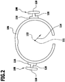
- eine schematische Draufsicht auf einen Verbindungsring und zwei Verriegelungselemente der Verbindungsvorrichtung aus
Fig. 1 , mit Blickrichtung längs einer Symmetrieachse des Verbindungsrings; - Fig. 3
- eine schematische perspektivische Darstellung der Verbindungsvorrichtung im verbundenen und verriegelten Zustand derselben;
- Fig. 4
- eine schematische Seitenansicht der Verbindungsvorrichtung im verbundenen und verriegelten Zustand derselben;
- Fig. 5
- einen schematischen Schnitt durch die Verbindungsvorrichtung in
Fig. 4 längs der Linie 5-5 inFig. 4 ; - Fig. 6
- eine schematische Draufsicht auf die Verbindungsvorrichtung im verbundenen und verriegelten Zustand derselben, mit Blickrichtung längs einer Verbindungsrichtung;
- Fig. 7
- eine der
Fig. 3 entsprechende schematische perspektivische Darstellung der Verbindungsvorrichtung im verbundenen aber entriegelten Zustand derselben; - Fig. 8
- eine der
Fig. 4 entsprechende schematische Seitenansicht der Verbindungsvorrichtung im verbundenen aber entriegelten Zustand derselben; - Fig. 9
- einen der
Fig. 5 entsprechenden schematischen Schnitt durch die Verbindungsvorrichtung inFig. 8 längs der Linie 9-9 inFig. 8 ; - Fig. 10
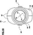
- eine der
Fig. 6 entsprechende schematische Draufsicht auf die Verbindungsvorrichtung im verbundenen aber entriegelten Zustand derselben, mit Blickrichtung längs der Verbindungsrichtung; - Fig. 11
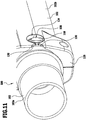
- eine schematische perspektivische Darstellung der Verbindungsvorrichtung in einem Zustand, in welchem ein Verriegelungselement durch einen Einführabschnitt hindurchgeführt wird; und
- Fig. 12
- eine der
Fig. 11 entsprechende schematische perspektivische Darstellung der Verbindungsvorrichtung in einem Zustand, in welchem das Verriegelungselement auf einer einer Aufnahmeöffnung zur Aufnahme des Verriegelungselements abgewandten Seite des Einführabschnitts angeordnet ist. - Gleiche oder funktional äquivalente Elemente sind in sämtlichen Figuren mit denselben Bezugszeichen versehen.
- Eine in den
Fig. 1 bis 12 dargestellte Ausführungsform einer als Ganzes mit 100 bezeichneten Verbindungsvorrichtung dient der Verbindung zweier Bauteile 102 miteinander. - Die Verbindungsvorrichtung 100 dient insbesondere der Verbindung oder Anbindung von Schläuchen, beispielsweise Saugschläuchen einer Saugvorrichtung.
- Die Verbindungsvorrichtung 100 umfasst hierzu ein erstes Bauteil 102a und ein zweites Bauteil 102b, welche lösbar miteinander verbindbar sind.
- Die beiden Bauteile 102 sind insbesondere im Wesentlichen rohrförmig und/oder hohlzylinderförmig ausgebildet.
- Das erste Bauteil 102a ist beispielsweise ein einstückig ausgebildetes Rohr.
- Das zweite Bauteil 102b ist beispielsweise durch zwei miteinander verschraubbare Halbschalen 104 gebildet.
- Das erste Bauteil 102a und das zweite Bauteil 102b sind vorzugsweise aus Kunststoff-Spritzgussbauteilen gebildet.
- Die Verbindungsvorrichtung 100 umfasst ferner einen Verbindungsring 106, an welchem zwei Verriegelungselemente 108 angeordnet sind.
- Wie insbesondere
Fig. 2 zu entnehmen ist, sind die Verriegelungselemente 108 insbesondere an bezüglich einer Symmetrieachse 111 des Verbindungsrings 106 aneinander gegenüberliegenden Seiten des Verbindungsrings 106 und einander abgewandt angeordnet. - Der Verbindungsring 106 und die Verriegelungselemente 108 sind vorzugsweise einstückig miteinander ausgebildet.
- Insbesondere sind der Verbindungsring 106 und die Verriegelungselemente 108 durch ein einstückiges Kunststoff-Spritzgussbauteil gebildet.
- Der Verbindungsring 106 ist insbesondere offen ausgebildet.
- Der Verbindungsring 106 ist vorzugsweise ferner elastisch, insbesondere reversibel verformbar, ausgebildet.
- Das erste Bauteil 102a umfasst einen Aufnahmeabschnitt 110, an welchem der Verbindungsring 106 anordenbar ist.
- Der Aufnahmeabschnitt 110 ist insbesondere als eine Aufnahmenut 112 ausgebildet, in welcher der Verbindungsring 106 aufnehmbar ist.
- Die Verriegelungselemente 108 ragen in jeweils einer senkrecht zur Symmetrieachse 111 verlaufenden radialen Richtung 114 nach außen von dem Verbindungsring 106 weg.
- Die Verriegelungselemente 108 umfassen jeweils einen Arretierabschnitt 116, einen Betätigungsabschnitt 118 und einen zwischen dem Arretierabschnitt 116 und dem Betätigungsabschnitt 118 angeordneten Stegabschnitt 120.
- In radialer Richtung 114 folgt dabei der Arretierabschnitt 116 auf den Verbindungsring 106, daran anschließend ist der Stegabschnitt 120 angeordnet, auf welchen schließlich der Betätigungsabschnitt 118 folgt.
- Wie insbesondere
Fig. 2 zu entnehmen ist, weisen der Arretierabschnitt 116 und der Betätigungsabschnitt 118 in einer senkrecht zur Symmetrieachse 111 und senkrecht zur radialen Richtung 114, längs welcher sich das jeweilige Verriegelungselement 108 erstreckt, verlaufenden Richtung jeweils eine größere Ausdehnung auf als der Stegabschnitt 122. - Das zweite Bauteil 102b umfasst eine Aufnahmeöffnung 124 zur Aufnahme der Verriegelungselemente 108, insbesondere der Arretierabschnitte 116 der Verriegelungselemente 108.
- An einem dem ersten Bauteil 102a zugewandten Ende 126 des zweiten Bauteils 102b sind zwei Einführabschnitte 128 angeordnet. Jeder Einführabschnitt 128 ist dabei einer Aufnahmeöffnung 124 zugeordnet und erstreckt sich ausgehend von dem Ende 126 in der Verbindungsrichtung 122 bis in die Aufnahmeöffnung 124 hinein.
- Jeder Einführabschnitt 128 umfasst dabei Einführschrägen 130, mittels welchen eine Verjüngung der Einführabschnitte 128 ausgehend von dem Ende 126 längs der Verbindungsrichtung 122 erzielt wird.
- Die Einführschrägen 130 schließen sich dann an jeweils eine Engstelle 132 des Einführabschnitts 128 an, an welche sich wiederum die jeweilige Aufnahmeöffnung 124 anschließt.
- Durch den Einführabschnitt 128 ist die Aufnahmeöffnung 124 zugänglich.
- Insbesondere kann das Verriegelungselement 108 durch den Einführabschnitt 128 hindurch der Aufnahmeöffnung 124 zugeführt werden.
- Wie insbesondere der in
Fig. 5 dargestellten Schnittdarstellung der Verbindungsvorrichtung 100 im verbundenen und verriegelten Zustand der zwei Bauteile 102 zu entnehmen ist, ragen die Verriegelungselemente 108 durch die Aufnahmeöffnungen 124 hindurch. Lediglich der Arretierabschnitt 116 eines jeden Verriegelungselements 108 ist dabei in der zugehörigen Aufnahmeöffnung 124 angeordnet. Die Stegabschnitte 120 und die Betätigungsabschnitte 118 ragen in radialer Richtung 114 über die Aufnahmeöffnungen 124 hinaus. - Wie insbesondere aus einem Vergleich der
Fig. 5 und9 hervorgeht, können die Verriegelungselemente 108 durch Applizieren einer in der radialen Richtung 114 nach innen gerichteten Druckkraft von einem Benutzer betätigt werden. - Die Verriegelungselemente 108 werden dann in der radialen Richtung 114 nach innen gerichtet verschoben, so dass die Arretierabschnitte 116 mit den Aufnahmeöffnungen 124 außer Eingriff gelangen und nunmehr die Stegabschnitte 120 in den Aufnahmeöffnungen 124 angeordnet sind.
- Da die Stegabschnitte 120 eine geringere seitliche Ausdehnung aufweisen als die Arretierabschnitte 116 und als die Engstelle 132, kann das erste Bauteil 102a zusammen mit dem Verbindungsring 106 und den Verriegelungselementen 108 in dieser in den
Fig. 7 bis 10 dargestellten entriegelten Stellung der Verbindungsvorrichtung 100 von dem zweiten Bauteil 102b entfernt werden. - Auch in der entriegelten Stellung der Verbindungsvorrichtung 100 ragen die Betätigungsabschnitte 118 in radialer Richtung 114 nach außen aus den Aufnahmeöffnungen 124 heraus. Auch während des Hindurchführens der Stegabschnitte 120 der Verriegelungselemente 108 durch die Einführabschnitte 128 sind die Betätigungsabschnitte 118 somit für einen Benutzer zugänglich, insbesondere von einem Benutzer berührbar.
- Wie insbesondere den
Fig. 5 und9 zu entnehmen ist, ist eine in radialer Richtung 114 genommene Länge L der Verriegelungselemente 108 größer als eine Strecke S, um welche die Verriegelungselemente 108 bewegt werden müssen, um aus der verriegelten Stellung (sieheFig. 3 bis 6 ) in die entriegelte Stellung (sieheFig. 7 bis 10 ) gebracht zu werden. - Die vorstehend beschriebene Verbindungsvorrichtung 100 funktioniert wie folgt:
- Zur Montage der Verbindungsvorrichtung 100 wird der Verbindungsring 106 in die Aufnahmenut 112 des ersten Bauteils 102a eingeclipst und damit lösbar an dem ersten Bauteil 102a, insbesondere an einem Einschubvorsprung 134 des ersten Bauteils 102a, festgelegt. Der Verbindungsring 106 ist dadurch vorzugsweise bezüglich der Verbindungsrichtung 122 formschlüssig, insbesondere unverschieblich, an dem ersten Bauteil 102a festgelegt.
- Zum Verbinden des ersten Bauteils 102a mit dem zweiten Bauteil 102b wird das erste Bauteil 102a in der Verbindungsrichtung 122 in das zweite Bauteil 102b hineingeschoben.
- Insbesondere wird das erste Bauteil 102a mit dem Einschubvorsprung 134 des ersten Bauteils 102a in eine Einschuböffnung 136 des zweiten Bauteils 102b eingeführt.
- Der in der Aufnahmenut 112 aufgenommene Verbindungsring 106 wird dabei ebenfalls in die Einschuböffnung 136 des zweiten Bauteils 102b eingeführt.
- Die Verriegelungselemente 108, welche seitlich von dem Verbindungsring 106 weg ragen, werden in die Einführabschnitte 128 des zweiten Bauteils 102b eingeführt und mittels der Einführschrägen 130 vorzugsweise so bewegt, dass ohne eine Betätigung der Verriegelungselemente 108 durch einen Benutzer, insbesondere ohne eine Betätigung der Betätigungsabschnitte 118 durch einen Benutzer, die Verriegelungselemente 108 aufeinander zu bewegt werden und somit die Verriegelungselemente 108 im Bereich der Stegabschnitte 120 durch die Engstellen 132 hindurch in die Aufnahmeöffnung 124 gelangen.
- Im Bereich der Aufnahmeöffnung 124 entspannt sich der Verbindungsring 106, so dass die Verriegelungselemente 108 voneinander entfernt werden und die Arretierabschnitte 116 der Verriegelungselemente 108 in die Aufnahmeöffnungen 124 eingreifen.
- Die Arretierabschnitte 116 weisen eine in einer senkrecht zur Verbindungsrichtung 122 und senkrecht zur radialen Richtung 114 verlaufenden Richtung größere Ausdehnung auf als die Stegabschnitte 120 und als die Engstellen 132, so dass mittels der Arretierabschnitte 116 eine bezüglich der Verbindungsrichtung 122 formschlüssige Verbindung zwischen den Verriegelungselementen 108 und dem zweiten Bauteil 102b und somit zwischen dem zweiten Bauteil 102b und dem ersten Bauteil 102a hergestellt ist.
- Zum Lösen der Verbindung wird von einem Benutzer eine Druckkraft auf die Betätigungsabschnitte 118 appliziert. Die Verriegelungselemente 108 werden dadurch erneut aufeinander zu bewegt, so dass die Arretierabschnitte 116 mit den Aufnahmeöffnungen 124 außer Eingriff gebracht werden und nunmehr wieder die Stegabschnitte 120 in den Aufnahmeöffnungen 124 angeordnet sind.
- In diesem in den
Fig. 7 bis 10 dargestellten entriegelten Zustand ist die formschlüssige Verbindung zwischen den zwei Bauteilen 102 längs der Verbindungsrichtung 122 aufgehoben, so dass die Verriegelungselemente 108 durch die Engstellen 132 und die Einführabschnitte 128 hindurchgeführt und somit von dem zweiten Bauteil 102b entfernt werden können (siehe insbesondere dieFig. 11 und12 ). - Somit sind auch die zwei Bauteile 102a, 102b erneut voneinander entfernbar.
- Dadurch, dass bei der beschriebenen Verbindungsvorrichtung 100 die Verriegelungselemente 108, insbesondere die Betätigungsabschnitte 118 der Verriegelungselemente 108, zu jedem Zeitpunkt, insbesondere während des Hindurchführens der Verriegelungselemente 108 durch die Einführabschnitte 128, für einen Benutzer zugänglich sind, kann die Verbindungsvorrichtung 100 besonders komfortabel bedient werden. Insbesondere können die zwei Bauteile 102a, 102b hierdurch besonders einfach und komfortabel voneinander entfernt werden.
-
- 100
- Verbindungsvorrichtung
- 102
- Bauteil
- 102a
- erstes Bauteil
- 102b
- zweites Bauteil
- 104
- Halbschale
- 106
- Verbindungsring
- 108
- Verriegelungselement
- 110
- Aufnahmeabschnitt
- 111
- Symmetrieachse
- 112
- Aufnahmenut
- 114
- radiale Richtung
- 116
- Arretierabschnitt
- 118
- Betätigungsabschnitt
- 120
- Stegabschnitt
- 122
- Verbindungsrichtung
- 124
- Aufnahmeöffnung
- 126
- Ende
- 128
- Einführabschnitt
- 130
- Einführschräge
- 132
- Engstelle
- 134
- Einschubvorsprung
- 136
- Einschuböffnung
- L
- Länge
- S
- Strecke
Claims (13)
- Verbindungsvorrichtung (100), umfassend ein erstes Bauteil (102a), ein mit dem ersten Bauteil (102a) lösbar verbindbares zweites Bauteil (102b) und ein Verriegelungselement (108), welches in einem Aufnahmeabschnitt (110) des ersten Bauteils (102a) aufnehmbar und zur Verriegelung einer Verbindung zwischen dem ersten Bauteil (102a) und dem zweiten Bauteil (102b) mit einer Aufnahmeöffnung (124) des zweiten Bauteils (102b) in Eingriff bringbar ist, wobei das Verriegelungselement (108) zur Entriegelung der Verbindung von einem Benutzer betätigbar ist,
dadurch gekennzeichnet,
dass die Aufnahmeöffnung (124) sich an einen Einführabschnitt (128) des zweiten Bauteils (102b) anschließt, durch welchen das Verriegelungselement (108) zum Verbinden der Bauteile (102) miteinander und/oder zum Lösen der Bauteile (102) voneinander hindurchführbar ist, wobei das Verriegelungselement (108) während des Hindurchführens des Verriegelungselements (108) durch den Einführabschnitt (128) für den Benutzer zugänglich, insbesondere von dem Benutzer betätigbar, ist,
wobei das Verriegelungselement (108)- einen Arretierabschnitt (116), mittels welchem das Verriegelungselement (108) die Aufnahmeöffnung (124) in einem verriegelten Zustand des Verriegelungselements (108) bezüglich einer Verbindungsrichtung (122) hintergreift,- einen Betätigungsabschnitt (118), an welchem ein Benutzer zur Betätigung des Verriegelungselements (108) angreift, und- einen Stegabschnitt (120), mittels welchem das Verriegelungselement (108) durch den Einführabschnitt (128) hindurchführbar ist,umfasst, wobei der Stegabschnitt (120) zwischen dem Arretierabschnitt (116) und dem Betätigungsabschnitt (118) angeordnet ist. - Verbindungsvorrichtung (100) nach Anspruch 1, dadurch gekennzeichnet, dass das Verriegelungselement (108) zur Entriegelung der Verbindung durch Applizieren einer Druckkraft mit der Aufnahmeöffnung (124) außer Eingriff bringbar ist.
- Verbindungsvorrichtung (100) nach einem der Ansprüche 1 oder 2, dadurch gekennzeichnet, dass das Verriegelungselement (108) während des Hindurchführens des Verriegelungselements (108) durch den Einführabschnitt (128) von dem Benutzer berührbar ist, insbesondere um eine Druckkraft auf das Verriegelungselement (108) auszuüben.
- Verbindungsvorrichtung (100) nach einem der Ansprüche 1 bis 3, dadurch gekennzeichnet, dass das Verriegelungselement (108) sich in einem verriegelten Zustand um eine Länge (L) in die Aufnahmeöffnung (124) hineinerstreckt oder durch die Aufnahmeöffnung (124) hindurcherstreckt, welche größer ist als eine Strecke (S), um welche das Verriegelungselement (108) bewegbar ist, um aus dem verriegelten Zustand in einen entriegelten Zustand gebracht zu werden, in welchem das Verriegelungselement (108) zum Entfernen der Bauteile (102) voneinander durch den Einführabschnitt (128) hindurchführbar ist.
- Verbindungsvorrichtung (100) nach einem der Ansprüche 1 bis 4, dadurch gekennzeichnet, dass die Verbindungsvorrichtung (100) einen geschlossenen oder offenen Verbindungsring (106) umfasst, an welchem ein oder mehrere Verriegelungselemente (108) angeordnet sind oder welcher ein oder mehrere Verriegelungselemente (108) umfasst.
- Verbindungsvorrichtung (100) nach Anspruch 5, dadurch gekennzeichnet, dass das eine Verriegelungselement (108) oder die mehreren Verriegelungselemente (108) bezüglich einer Symmetrieachse (111) des Verbindungsrings (106) in im Wesentlichen radialer Richtung (114) nach außen weg ragen.
- Verbindungsvorrichtung (100) nach einem der Ansprüche 5 oder 6, dadurch gekennzeichnet, dass die Verbindungsvorrichtung (100) zwei oder mehr Verriegelungselemente (108) umfasst, welche auf bezüglich einer Symmetrieachse (111) des Verbindungsrings (106) einander gegenüberliegenden Seiten des Verbindungsrings (106) angeordnet sind.
- Verbindungsvorrichtung (100) nach einem der Ansprüche 5 bis 7, dadurch gekennzeichnet, dass der Verbindungsring (106) elastisch ausgebildet ist und/oder durch Betätigung des einen Verriegelungselements (108) oder der mehreren Verriegelungselemente (108), insbesondere federnd, verformbar ist.
- Verbindungsvorrichtung (100) nach einem der Ansprüche 5 bis 8, dadurch gekennzeichnet, dass der Aufnahmeabschnitt (110) des ersten Bauteils (102a) als eine im Wesentlichen ringförmige Aufnahmenut (112) ausgebildet ist, in welcher der Verbindungsring (106) anordenbar oder angeordnet ist.
- Verbindungsvorrichtung (100) nach einem der Ansprüche 1 bis 9, dadurch gekennzeichnet, dass der Einführabschnitt (128) mindestens eine Einführschräge (130) aufweist, mittels welcher das Verriegelungselement (108) beim Verbinden der Bauteile (102) einer Engstelle (132) des Einführabschnitts (128) zuführbar ist.
- Verbindungsvorrichtung (100) nach einem der Ansprüche 1 bis 10, dadurch gekennzeichnet, dass das Verriegelungselement (108) oder die Verriegelungselemente (108) und/oder ein Verbindungsring (106) in einem verriegelten Zustand der Bauteile (102) zumindest abschnittsweise zwischen den Bauteilen (102) angeordnet sind.
- Verbindungsvorrichtung (100) nach einem der Ansprüche 1 bis 11, dadurch gekennzeichnet, dass das erste Bauteil (102a) und/oder das zweite Bauteil (102b) im Wesentlichen hohlzylindrisch und/oder rohrförmig ausgebildet sind.
- Verbindungsvorrichtung (100) nach einem der Ansprüche 1 bis 12, dadurch gekennzeichnet, dass die Bauteile (102) durch Aufschieben des einen Bauteils (102) auf das andere Bauteil (102) miteinander verbindbar und dass das Verriegelungselement (108) oder die Verriegelungselemente (108) durch das Aufschieben ohne Betätigung desselben beziehungsweise derselben durch den Benutzer in den verriegelten Zustand bringbar sind.
Applications Claiming Priority (2)
| Application Number | Priority Date | Filing Date | Title |
|---|---|---|---|
| DE201310217557 DE102013217557A1 (de) | 2013-09-03 | 2013-09-03 | Verbindungsvorrichtung |
| PCT/EP2014/067635 WO2015032615A1 (de) | 2013-09-03 | 2014-08-19 | Verbindungsvorrichtung |
Publications (2)
| Publication Number | Publication Date |
|---|---|
| EP3041395A1 EP3041395A1 (de) | 2016-07-13 |
| EP3041395B1 true EP3041395B1 (de) | 2017-03-01 |
Family
ID=51422057
Family Applications (1)
| Application Number | Title | Priority Date | Filing Date |
|---|---|---|---|
| EP14756012.2A Active EP3041395B1 (de) | 2013-09-03 | 2014-08-19 | Verbindungsvorrichtung |
Country Status (3)
| Country | Link |
|---|---|
| EP (1) | EP3041395B1 (de) |
| DE (1) | DE102013217557A1 (de) |
| WO (1) | WO2015032615A1 (de) |
Families Citing this family (2)
| Publication number | Priority date | Publication date | Assignee | Title |
|---|---|---|---|---|
| EP3367867B1 (de) * | 2015-10-27 | 2021-09-08 | Alfred Kärcher SE & Co. KG | Verbindungsvorrichtung zum verbinden von saugleitungen sowie sauggerät |
| DE102024130230A1 (de) * | 2024-10-17 | 2026-04-23 | Miele & Cie. Kg | Set zur Befestigung an einer Saugvorrichtung zur Reinigung einer Fläche |
Family Cites Families (7)
| Publication number | Priority date | Publication date | Assignee | Title |
|---|---|---|---|---|
| DE1717986U (de) * | 1954-12-23 | 1956-03-01 | Siemens Ag | Rohrverbindung, insbesondere fuer staubsaugerrohre. |
| FR1306785A (fr) * | 1961-11-03 | 1962-10-19 | Ici Ltd | Perfectionnements aux agrafes |
| DE2829938A1 (de) * | 1978-07-07 | 1980-01-24 | Mauz & Pfeiffer Progress | Steckverbindung |
| DE4318878A1 (de) * | 1993-06-08 | 1994-12-15 | Kuehner Gmbh & Cie | Kältemittelkupplung zur Verbindung von Kältemittelleitungen |
| FR2846069B1 (fr) * | 2002-10-16 | 2005-01-14 | Valeo Climatisation | Dispositif de raccord rapide pour echangeur de chaleur |
| DE102004038630A1 (de) * | 2004-08-09 | 2006-02-23 | BSH Bosch und Siemens Hausgeräte GmbH | Kupplung zum Verbinden eines Staubsaugerschlauchs mit einem Rohr |
| DE102006010316A1 (de) * | 2006-03-07 | 2007-09-13 | Karl Storz Gmbh & Co. Kg | Kupplungsmechanismus |
-
2013
- 2013-09-03 DE DE201310217557 patent/DE102013217557A1/de not_active Withdrawn
-
2014
- 2014-08-19 WO PCT/EP2014/067635 patent/WO2015032615A1/de not_active Ceased
- 2014-08-19 EP EP14756012.2A patent/EP3041395B1/de active Active
Also Published As
| Publication number | Publication date |
|---|---|
| DE102013217557A1 (de) | 2015-03-05 |
| WO2015032615A1 (de) | 2015-03-12 |
| EP3041395A1 (de) | 2016-07-13 |
Similar Documents
| Publication | Publication Date | Title |
|---|---|---|
| EP1998901B1 (de) | Austraganordnung mit abnehmbar befestigbaren zubehörteilen | |
| EP1969279A1 (de) | Kupplungsteil für steckverbinderanordnung | |
| DE102012003014A1 (de) | Befestigungsvorrichtung für eine Bänderung | |
| DE60131136T2 (de) | Verbindungsstück für die verlängerung für einen werkzeuggriff | |
| EP3318368B1 (de) | Lösbare stielbefestigungskupplung für arbeitsgeräte | |
| EP2401953B1 (de) | Kupplung zum lösbaren Verbinden eines Okulars eines Endoskops mit einer Kamera | |
| DE102012209940A1 (de) | Stangenanordnung | |
| DE102008000158A1 (de) | Handgriff für ein insbesondere motorisch angetriebenes Werkzeug | |
| DE102008050477A1 (de) | Kochgeschirr mit abnehmbarem Griff- oder Stielelement | |
| EP2965843A1 (de) | Spannfutter und spannmittel mit schnellwechselfunktion | |
| EP0303889B1 (de) | Kerbzange zum Aufpressen von Aderendhülsen, Kabelschuhen und -verbindern auf elektrische Leiter | |
| EP2732778B1 (de) | Medizinisches Instrument | |
| EP2233086B1 (de) | Vorrichtung zum Entfernen von Parasiten | |
| EP3041395A1 (de) | Verbindungsvorrichtung | |
| DE102010026100A1 (de) | Schnellkupplung für Fluidleitungen | |
| DE102015204501A1 (de) | Schnellwechselsystem für Greiferelemente zum Erfassen und Transportieren von Werkstücken | |
| EP3208567B1 (de) | Schalldämpfer | |
| DE20114744U1 (de) | Trägervorrichtung für Reinigungsbezüge | |
| EP1978290A1 (de) | Vorrichtung zum Anschliessen einer röhrenartigen Leitung, insbesondere einer Schlauchleitung, an ein Anschlussstück | |
| DE102022109557B3 (de) | Verbindungsabschnitt einer Maschine und eine Maschine mit einem solchen Verbindungsabschnitt | |
| DE202011106800U1 (de) | Wechselstiel für Gartengeräte oder Haushaltsgeräte | |
| DE102012223284B4 (de) | Sicherungsanordnung mit Griffanordnung zum Sichern und Entsichern eines oder mehrerer Bauteile | |
| DE19910075C1 (de) | Halterungsvorrichtung für eine Diebstahlschutzvorrichtung | |
| EP3423289A1 (de) | Schreibgerät mit zwei schreibspitzen | |
| DE102017200175A1 (de) | Rastclip |
Legal Events
| Date | Code | Title | Description |
|---|---|---|---|
| PUAI | Public reference made under article 153(3) epc to a published international application that has entered the european phase |
Free format text: ORIGINAL CODE: 0009012 |
|
| 17P | Request for examination filed |
Effective date: 20160229 |
|
| AK | Designated contracting states |
Kind code of ref document: A1 Designated state(s): AL AT BE BG CH CY CZ DE DK EE ES FI FR GB GR HR HU IE IS IT LI LT LU LV MC MK MT NL NO PL PT RO RS SE SI SK SM TR |
|
| AX | Request for extension of the european patent |
Extension state: BA ME |
|
| GRAP | Despatch of communication of intention to grant a patent |
Free format text: ORIGINAL CODE: EPIDOSNIGR1 |
|
| DAX | Request for extension of the european patent (deleted) | ||
| INTG | Intention to grant announced |
Effective date: 20161025 |
|
| GRAS | Grant fee paid |
Free format text: ORIGINAL CODE: EPIDOSNIGR3 |
|
| GRAA | (expected) grant |
Free format text: ORIGINAL CODE: 0009210 |
|
| AK | Designated contracting states |
Kind code of ref document: B1 Designated state(s): AL AT BE BG CH CY CZ DE DK EE ES FI FR GB GR HR HU IE IS IT LI LT LU LV MC MK MT NL NO PL PT RO RS SE SI SK SM TR |
|
| REG | Reference to a national code |
Ref country code: GB Ref legal event code: FG4D Free format text: NOT ENGLISH |
|
| REG | Reference to a national code |
Ref country code: CH Ref legal event code: EP Ref country code: AT Ref legal event code: REF Ref document number: 870306 Country of ref document: AT Kind code of ref document: T Effective date: 20170315 |
|
| REG | Reference to a national code |
Ref country code: IE Ref legal event code: FG4D Free format text: LANGUAGE OF EP DOCUMENT: GERMAN |
|
| REG | Reference to a national code |
Ref country code: DE Ref legal event code: R096 Ref document number: 502014002877 Country of ref document: DE |
|
| REG | Reference to a national code |
Ref country code: NL Ref legal event code: MP Effective date: 20170301 |
|
| REG | Reference to a national code |
Ref country code: LT Ref legal event code: MG4D |
|
| REG | Reference to a national code |
Ref country code: FR Ref legal event code: PLFP Year of fee payment: 4 |
|
| PG25 | Lapsed in a contracting state [announced via postgrant information from national office to epo] |
Ref country code: GR Free format text: LAPSE BECAUSE OF FAILURE TO SUBMIT A TRANSLATION OF THE DESCRIPTION OR TO PAY THE FEE WITHIN THE PRESCRIBED TIME-LIMIT Effective date: 20170602 Ref country code: NO Free format text: LAPSE BECAUSE OF FAILURE TO SUBMIT A TRANSLATION OF THE DESCRIPTION OR TO PAY THE FEE WITHIN THE PRESCRIBED TIME-LIMIT Effective date: 20170601 Ref country code: HR Free format text: LAPSE BECAUSE OF FAILURE TO SUBMIT A TRANSLATION OF THE DESCRIPTION OR TO PAY THE FEE WITHIN THE PRESCRIBED TIME-LIMIT Effective date: 20170301 Ref country code: LT Free format text: LAPSE BECAUSE OF FAILURE TO SUBMIT A TRANSLATION OF THE DESCRIPTION OR TO PAY THE FEE WITHIN THE PRESCRIBED TIME-LIMIT Effective date: 20170301 Ref country code: FI Free format text: LAPSE BECAUSE OF FAILURE TO SUBMIT A TRANSLATION OF THE DESCRIPTION OR TO PAY THE FEE WITHIN THE PRESCRIBED TIME-LIMIT Effective date: 20170301 |
|
| PG25 | Lapsed in a contracting state [announced via postgrant information from national office to epo] |
Ref country code: LV Free format text: LAPSE BECAUSE OF FAILURE TO SUBMIT A TRANSLATION OF THE DESCRIPTION OR TO PAY THE FEE WITHIN THE PRESCRIBED TIME-LIMIT Effective date: 20170301 Ref country code: BG Free format text: LAPSE BECAUSE OF FAILURE TO SUBMIT A TRANSLATION OF THE DESCRIPTION OR TO PAY THE FEE WITHIN THE PRESCRIBED TIME-LIMIT Effective date: 20170601 Ref country code: RS Free format text: LAPSE BECAUSE OF FAILURE TO SUBMIT A TRANSLATION OF THE DESCRIPTION OR TO PAY THE FEE WITHIN THE PRESCRIBED TIME-LIMIT Effective date: 20170301 Ref country code: SE Free format text: LAPSE BECAUSE OF FAILURE TO SUBMIT A TRANSLATION OF THE DESCRIPTION OR TO PAY THE FEE WITHIN THE PRESCRIBED TIME-LIMIT Effective date: 20170301 Ref country code: ES Free format text: LAPSE BECAUSE OF FAILURE TO SUBMIT A TRANSLATION OF THE DESCRIPTION OR TO PAY THE FEE WITHIN THE PRESCRIBED TIME-LIMIT Effective date: 20170301 |
|
| PG25 | Lapsed in a contracting state [announced via postgrant information from national office to epo] |
Ref country code: NL Free format text: LAPSE BECAUSE OF FAILURE TO SUBMIT A TRANSLATION OF THE DESCRIPTION OR TO PAY THE FEE WITHIN THE PRESCRIBED TIME-LIMIT Effective date: 20170301 |
|
| PG25 | Lapsed in a contracting state [announced via postgrant information from national office to epo] |
Ref country code: IT Free format text: LAPSE BECAUSE OF FAILURE TO SUBMIT A TRANSLATION OF THE DESCRIPTION OR TO PAY THE FEE WITHIN THE PRESCRIBED TIME-LIMIT Effective date: 20170301 Ref country code: CZ Free format text: LAPSE BECAUSE OF FAILURE TO SUBMIT A TRANSLATION OF THE DESCRIPTION OR TO PAY THE FEE WITHIN THE PRESCRIBED TIME-LIMIT Effective date: 20170301 Ref country code: SK Free format text: LAPSE BECAUSE OF FAILURE TO SUBMIT A TRANSLATION OF THE DESCRIPTION OR TO PAY THE FEE WITHIN THE PRESCRIBED TIME-LIMIT Effective date: 20170301 Ref country code: EE Free format text: LAPSE BECAUSE OF FAILURE TO SUBMIT A TRANSLATION OF THE DESCRIPTION OR TO PAY THE FEE WITHIN THE PRESCRIBED TIME-LIMIT Effective date: 20170301 Ref country code: RO Free format text: LAPSE BECAUSE OF FAILURE TO SUBMIT A TRANSLATION OF THE DESCRIPTION OR TO PAY THE FEE WITHIN THE PRESCRIBED TIME-LIMIT Effective date: 20170301 |
|
| PG25 | Lapsed in a contracting state [announced via postgrant information from national office to epo] |
Ref country code: SM Free format text: LAPSE BECAUSE OF FAILURE TO SUBMIT A TRANSLATION OF THE DESCRIPTION OR TO PAY THE FEE WITHIN THE PRESCRIBED TIME-LIMIT Effective date: 20170301 Ref country code: PT Free format text: LAPSE BECAUSE OF FAILURE TO SUBMIT A TRANSLATION OF THE DESCRIPTION OR TO PAY THE FEE WITHIN THE PRESCRIBED TIME-LIMIT Effective date: 20170703 Ref country code: PL Free format text: LAPSE BECAUSE OF FAILURE TO SUBMIT A TRANSLATION OF THE DESCRIPTION OR TO PAY THE FEE WITHIN THE PRESCRIBED TIME-LIMIT Effective date: 20170301 Ref country code: IS Free format text: LAPSE BECAUSE OF FAILURE TO SUBMIT A TRANSLATION OF THE DESCRIPTION OR TO PAY THE FEE WITHIN THE PRESCRIBED TIME-LIMIT Effective date: 20170701 |
|
| REG | Reference to a national code |
Ref country code: DE Ref legal event code: R097 Ref document number: 502014002877 Country of ref document: DE |
|
| PLBE | No opposition filed within time limit |
Free format text: ORIGINAL CODE: 0009261 |
|
| STAA | Information on the status of an ep patent application or granted ep patent |
Free format text: STATUS: NO OPPOSITION FILED WITHIN TIME LIMIT |
|
| PG25 | Lapsed in a contracting state [announced via postgrant information from national office to epo] |
Ref country code: DK Free format text: LAPSE BECAUSE OF FAILURE TO SUBMIT A TRANSLATION OF THE DESCRIPTION OR TO PAY THE FEE WITHIN THE PRESCRIBED TIME-LIMIT Effective date: 20170301 |
|
| 26N | No opposition filed |
Effective date: 20171204 |
|
| PG25 | Lapsed in a contracting state [announced via postgrant information from national office to epo] |
Ref country code: SI Free format text: LAPSE BECAUSE OF FAILURE TO SUBMIT A TRANSLATION OF THE DESCRIPTION OR TO PAY THE FEE WITHIN THE PRESCRIBED TIME-LIMIT Effective date: 20170301 |
|
| REG | Reference to a national code |
Ref country code: CH Ref legal event code: PL |
|
| PG25 | Lapsed in a contracting state [announced via postgrant information from national office to epo] |
Ref country code: MC Free format text: LAPSE BECAUSE OF FAILURE TO SUBMIT A TRANSLATION OF THE DESCRIPTION OR TO PAY THE FEE WITHIN THE PRESCRIBED TIME-LIMIT Effective date: 20170301 |
|
| PG25 | Lapsed in a contracting state [announced via postgrant information from national office to epo] |
Ref country code: LI Free format text: LAPSE BECAUSE OF NON-PAYMENT OF DUE FEES Effective date: 20170831 Ref country code: CH Free format text: LAPSE BECAUSE OF NON-PAYMENT OF DUE FEES Effective date: 20170831 |
|
| REG | Reference to a national code |
Ref country code: IE Ref legal event code: MM4A |
|
| REG | Reference to a national code |
Ref country code: BE Ref legal event code: MM Effective date: 20170831 |
|
| PG25 | Lapsed in a contracting state [announced via postgrant information from national office to epo] |
Ref country code: LU Free format text: LAPSE BECAUSE OF NON-PAYMENT OF DUE FEES Effective date: 20170819 |
|
| REG | Reference to a national code |
Ref country code: FR Ref legal event code: PLFP Year of fee payment: 5 |
|
| PG25 | Lapsed in a contracting state [announced via postgrant information from national office to epo] |
Ref country code: IE Free format text: LAPSE BECAUSE OF NON-PAYMENT OF DUE FEES Effective date: 20170819 |
|
| PG25 | Lapsed in a contracting state [announced via postgrant information from national office to epo] |
Ref country code: BE Free format text: LAPSE BECAUSE OF NON-PAYMENT OF DUE FEES Effective date: 20170831 |
|
| PG25 | Lapsed in a contracting state [announced via postgrant information from national office to epo] |
Ref country code: MT Free format text: LAPSE BECAUSE OF FAILURE TO SUBMIT A TRANSLATION OF THE DESCRIPTION OR TO PAY THE FEE WITHIN THE PRESCRIBED TIME-LIMIT Effective date: 20170301 |
|
| PG25 | Lapsed in a contracting state [announced via postgrant information from national office to epo] |
Ref country code: HU Free format text: LAPSE BECAUSE OF FAILURE TO SUBMIT A TRANSLATION OF THE DESCRIPTION OR TO PAY THE FEE WITHIN THE PRESCRIBED TIME-LIMIT; INVALID AB INITIO Effective date: 20140819 |
|
| PG25 | Lapsed in a contracting state [announced via postgrant information from national office to epo] |
Ref country code: CY Free format text: LAPSE BECAUSE OF FAILURE TO SUBMIT A TRANSLATION OF THE DESCRIPTION OR TO PAY THE FEE WITHIN THE PRESCRIBED TIME-LIMIT Effective date: 20170301 |
|
| PG25 | Lapsed in a contracting state [announced via postgrant information from national office to epo] |
Ref country code: MK Free format text: LAPSE BECAUSE OF FAILURE TO SUBMIT A TRANSLATION OF THE DESCRIPTION OR TO PAY THE FEE WITHIN THE PRESCRIBED TIME-LIMIT Effective date: 20170301 |
|
| PG25 | Lapsed in a contracting state [announced via postgrant information from national office to epo] |
Ref country code: TR Free format text: LAPSE BECAUSE OF FAILURE TO SUBMIT A TRANSLATION OF THE DESCRIPTION OR TO PAY THE FEE WITHIN THE PRESCRIBED TIME-LIMIT Effective date: 20170301 |
|
| PG25 | Lapsed in a contracting state [announced via postgrant information from national office to epo] |
Ref country code: AL Free format text: LAPSE BECAUSE OF FAILURE TO SUBMIT A TRANSLATION OF THE DESCRIPTION OR TO PAY THE FEE WITHIN THE PRESCRIBED TIME-LIMIT Effective date: 20170301 |
|
| REG | Reference to a national code |
Ref country code: AT Ref legal event code: MM01 Ref document number: 870306 Country of ref document: AT Kind code of ref document: T Effective date: 20190819 |
|
| PG25 | Lapsed in a contracting state [announced via postgrant information from national office to epo] |
Ref country code: AT Free format text: LAPSE BECAUSE OF NON-PAYMENT OF DUE FEES Effective date: 20190819 |
|
| REG | Reference to a national code |
Ref country code: DE Ref legal event code: R082 Ref document number: 502014002877 Country of ref document: DE Representative=s name: DTS PATENT- UND RECHTSANWAELTE SCHNEKENBUEHL U, DE Ref country code: DE Ref legal event code: R082 Ref document number: 502014002877 Country of ref document: DE Representative=s name: DTS PATENT- UND RECHTSANWAELTE PARTMBB, DE |
|
| PGFP | Annual fee paid to national office [announced via postgrant information from national office to epo] |
Ref country code: GB Payment date: 20220824 Year of fee payment: 9 |
|
| GBPC | Gb: european patent ceased through non-payment of renewal fee |
Effective date: 20230819 |
|
| PG25 | Lapsed in a contracting state [announced via postgrant information from national office to epo] |
Ref country code: GB Free format text: LAPSE BECAUSE OF NON-PAYMENT OF DUE FEES Effective date: 20230819 |
|
| PG25 | Lapsed in a contracting state [announced via postgrant information from national office to epo] |
Ref country code: GB Free format text: LAPSE BECAUSE OF NON-PAYMENT OF DUE FEES Effective date: 20230819 |
|
| PGFP | Annual fee paid to national office [announced via postgrant information from national office to epo] |
Ref country code: FR Payment date: 20240821 Year of fee payment: 11 |
|
| PGFP | Annual fee paid to national office [announced via postgrant information from national office to epo] |
Ref country code: DE Payment date: 20250819 Year of fee payment: 12 |