EP3041358B1 - Backvorrichtung - Google Patents
Backvorrichtung Download PDFInfo
- Publication number
- EP3041358B1 EP3041358B1 EP14756037.9A EP14756037A EP3041358B1 EP 3041358 B1 EP3041358 B1 EP 3041358B1 EP 14756037 A EP14756037 A EP 14756037A EP 3041358 B1 EP3041358 B1 EP 3041358B1
- Authority
- EP
- European Patent Office
- Prior art keywords
- drum
- baking
- roller
- trailing
- baking apparatus
- Prior art date
- Legal status (The legal status is an assumption and is not a legal conclusion. Google has not performed a legal analysis and makes no representation as to the accuracy of the status listed.)
- Active
Links
- 238000005096 rolling process Methods 0.000 claims description 20
- 230000007935 neutral effect Effects 0.000 claims description 12
- 238000010438 heat treatment Methods 0.000 claims description 10
- 230000005484 gravity Effects 0.000 claims description 9
- 239000007788 liquid Substances 0.000 claims description 3
- 230000032258 transport Effects 0.000 claims 1
- 238000004519 manufacturing process Methods 0.000 description 3
- 238000010276 construction Methods 0.000 description 2
- 238000012423 maintenance Methods 0.000 description 2
- 238000005520 cutting process Methods 0.000 description 1
- 230000000694 effects Effects 0.000 description 1
- 230000006698 induction Effects 0.000 description 1
- 239000000463 material Substances 0.000 description 1
- 238000000034 method Methods 0.000 description 1
- 235000012431 wafers Nutrition 0.000 description 1
- 238000004804 winding Methods 0.000 description 1
Images

Classifications
-
- A—HUMAN NECESSITIES
- A21—BAKING; EDIBLE DOUGHS
- A21B—BAKERS' OVENS; MACHINES OR EQUIPMENT FOR BAKING
- A21B1/00—Bakers' ovens
- A21B1/42—Bakers' ovens characterised by the baking surfaces moving during the baking
- A21B1/48—Bakers' ovens characterised by the baking surfaces moving during the baking with surfaces in the form of an endless band
-
- A—HUMAN NECESSITIES
- A21—BAKING; EDIBLE DOUGHS
- A21B—BAKERS' OVENS; MACHINES OR EQUIPMENT FOR BAKING
- A21B5/00—Baking apparatus for special goods; Other baking apparatus
- A21B5/02—Apparatus for baking hollow articles, waffles, pastry, biscuits, or the like
Definitions
- the invention relates to a baking device for producing endless belts of preferably liquid baking masses on a rotating in a machine frame, at least partially heated baking tray carrier, the at least one endless baking surface by at least one stationarily arranged in the machine frame, containing a heater, ranging from a baking mass applicator to a tape take-off device Baking zone transported, wherein a rotatably mounted and driven hubless drum is provided as a circulating heated baking surface carrier.
- Such baking device is from the WO97 / 34492 A1 known.
- the invention relates to a baking apparatus comprising a rotatably mounted and driven drum which is guided in a machine frame. Similar devices are known and published in different embodiments.
- the drum is mounted in the region of the axis with a loose-bearing arrangement such that a lateral movement is prevented.
- the baking surface carrier itself is wheel-shaped or cylindrical and has connecting elements that extend from its outer region to the wheel hub. This connection of the outer baking surface and the wheel hub has the disadvantage that in the interior of the baking surface carrier no further elements such as heating elements or baking mass applicators can be provided.
- This hubless arrangement usually has a drive roller in the lower region, on which the back ring rests.
- the back rings have for example a diameter of about one to 2.5 meters and a width of about 20cm to 60cm.
- the object of the invention is to provide a baking device of the type mentioned above, in which the hubless drum is guided, wherein the guide is simple, low-wear, low maintenance and reliable.
- the baking device for producing endless belts of preferably liquid baking masses on a rotating in a machine frame, at least partially heated baking tray carrier, the at least one endless baking surface by at least one stationary in the machine frame arranged, containing a heater, ranging from a baking mass applicator to a tape take-off device Transported backzone, wherein a rotatably mounted and driven hubless drum is provided as a circulating heated baking surface carrier, in that a trailing roller arranged pivotably about a steering axis is provided which rolls in a contact area on a rolling surface of the drum, wherein a trailing distance is provided between the intersection of the steering axis with the rolling surface and the contact area, that the rolling surface is a lateral surface of the drum, that the rolling surface is an inner circumferential surface of the drum, that the follower roller is rotatably mounted about a wheel axis on a follower link and / or that the follower link is rotatably mounted about the steering axis on the machine frame.
- the invention may be characterized in that the steering axis is substantially orthogonal to the wheel axis, that the drum is supported against gravity on the follower roller, that the drum is arranged hanging on a drive roller for the rotary drive of the drum that the drum is hollow cylindrical and comprises an inner circumferential surface and an outer lateral surface, that the drive roller and the idler roll on the inner circumferential surface, that a baking surface is provided on the outer lateral surface and / or that upon pivoting of the trailing arm from the neutral position, in particular, by the rotation of the drum a restoring moment is generated in the neutral position, wherein in the neutral position the steering axis and the center of gravity of the instantaneous contact region of the follower roller lie with the rolling surface in a plane, wherein the plane is a normal plane of the axis of rotation of the drum or the axis of rotation the trailing roller and the axis of rotation of the drive roller are parallel, that at least one guide roller is provided on both sides of the drum, that the guide rollers touch
- the device comprises a machine frame on which a baking tray carrier is provided.
- a baking tray carrier is provided.
- This is preferably designed as a hollow cylindrical body which can be heated or heated by a stationarily arranged heating device, so that a baking zone is formed between a baking mass application device and a strip removal device.
- the baking surface carrier is arranged hanging on a drive roller and driven in rotation by the drive roller.
- the drive roller is provided in the upper region of the baking surface carrier.
- the baking surface carrier which is designed in particular ring-shaped, has a top dead center.
- the top dead center corresponds to that point of the cylindrical body which corresponds to the highest point of the upright drum.
- the drive roller is arranged in a region outside this top dead center.
- the touches Drive roller the baking surface carrier in an angular range of about 1 ° to 90 ° before or after top dead center.
- the tracking roller In order to keep the baking surface carrier against gravity in this position, the tracking roller according to the invention is provided. This is coupled to the machine frame and applied to the baking surface carrier. As a result, the baking surface carrier is supported against the force of gravity on the follower roller.
- the follower roller is rotatably mounted about a wheel axle and rolls off on a rolling surface of the baking surface carrier.
- the follower roller is rotatably mounted on a follower link.
- the trailing link is preferably rotatably mounted about a steering axis, wherein preferably the steering axis and the wheel axis have a normal distance not equal to zero to each other.
- the steering axis is preferably in a normal plane of the axis of rotation of the drum.
- the follower roller touches the rolling surface of the baking surface carrier in a contact area.
- This contact area is the area in which contact between the baking tray carrier and the trailing roller is possible within the framework of the kinematics.
- the contact area substantially corresponds to a three-dimensionally curved arcuate portion.
- the trailing roller has a stable position in a central region, ie in the neutral position. In the neutral position, e.g. the steering axis and the center of gravity of the instantaneous contact area of the follower roller with the rolling surface in a plane, wherein the plane is a normal plane of the axis of rotation of the drum.
- the cutting axis of the steering axis with the rolling surface and the contact area have a certain trailing distance.
- the follower roller is pressed by the rotation of the baking tray carrier in the neutral position.
- a restoring moment is effected in the neutral position by the rotation of the baking surface carrier.
- a guide of the baking surface carrier or the drum is effected by self-centering.
- the steering axis is arranged substantially orthogonal to the axis of rotation of the follower roller. This means that the two axes of rotation are normal to each other. However, this does not necessarily mean that the two axes have an intersection point. Preferably, there is no intersection.
- the rolling surface is that surface of the baking surface carrier, on which the trailing roller unrolls.
- This can be a surface, for example a cylindrical surface.
- sections, segmented, ribbed or similar surfaces may be provided as rolling surfaces.
- An angle range is defined as a range of angles measured from the center of the tray carrier in or against the rotation of the tray carrier.
- the drum guide rollers can be provided for lateral guidance of the drum guide rollers. These are arranged in particular in the region of the drive roller and guide the drum in the upper region.
- the guide rollers are arranged such that they roll for guidance laterally on the end face of the drum. They are adapted to carry out a supporting correction of the slight sideways running of the ring caused by manufacturing tolerances.
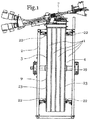
- Fig. 1 shows a baking device according to the invention from above. It should be noted that this illustration is a schematic representation.
- the device comprises a machine frame 2, a baking tray carrier 3 with a baking surface 4, on which four belts 1 are baked.
- the baking surface carrier 3 is designed substantially cylindrical, wherein the axis of rotation of this cylinder in the representation of Fig. 1 essentially in the image plane.
- the baking mass application device 6 and the heating device 5 are not shown in the present schematic representation.
- the strip removal device 7 is set up to remove the strips from the baking surface carrier 3 or the baking surface 4 and to further process them. In particular, a winding of the dough bands 1 can be made into elongated tubes.
- the baking surface carrier 3 is designed in the present embodiment as a drum 9 and in particular as a hubless drum.
- the drum 9 or the baking surface carrier 3 are rotatably arranged and driven.
- the drive takes place in the present embodiment via the drive roller 19 which contacts the drum 9.
- the drive roller 19 is driven by a rotary drive, not shown.
- 9 guide rollers 22 are provided laterally on the end face 23 of the drum.
- the guide rollers 22 are connected to the machine frame 2 and rotatably supported. Between the paired rollers 22 there is a free space, which corresponds substantially to the width of the baking surface carrier or the drum 9.
- the side guide of the drum 9 thus produced to a certain excess, so that the compressive forces and wear between the end face 23 of the drum 9 and the guide rollers 22 are kept small.
- the guide rollers 22 may also be spring-mounted.
- the axes of rotation of the guide rollers are essentially normal to the local curvature of the drum in Berparberich.
- the axes of rotation of the guide rollers 22 are arranged in the radial direction to the axis of rotation of the drum 9.
- the guide rollers 22 roll on the end faces 23 of the drum 9.
- the tape removal device corresponds to a conventional tape removal device.
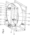
- Fig. 2 shows a schematic oblique view of the device according to the invention.
- the view essentially corresponds to a view from diagonally below.
- the device comprises a machine frame 2, a baking surface carrier 3, which is preferably designed as a drum 9.
- the drum 9 is hubleless and / or annular.
- the shape of the drum 9 substantially corresponds to a hollow cylinder. This has a cylindrical outer surface and a cylindrical inner surface.
- an inner lateral surface 20 and an outer lateral surface 21 are provided.
- Rotatable and driven, the drive roller 19 is coupled to the machine frame 2.
- the drive roller 19 can be driven via a rotary drive. Hanging on the drive roller 19, the drum 9 is provided.
- the drive roller 19 touches the drum 9 on the inner circumferential surface 20. Further, guide rollers 22 are provided adjacent to the end faces 23 of the drum 9. In the schematic representation of Fig. 2 lateral support elements of the machine frame 2 are hidden, so that the device is shown clearly arranged. In particular, the components baking belt removal device 7, baking mass application device 6 and heating device 5 are hidden.
- a follower roller 11 is provided.
- This follower roller 11 rolls on the drum 9, in particular to effect a support of the drum.
- the follower roller 11 is provided on a trailing link 18.
- the trailing link 18 and / or the trailing roller 11 are movably coupled to the machine frame 2.
- the drum has an axis of rotation 27, which is preferably arranged stationary. However, the area of the rotation axis 27 is substantially free of physical objects. As stated above, it is preferably a hubless drum 9.
- Fig. 3 shows a schematic sectional view of the device according to the invention.
- the baking mass application device 6 corresponds to a conventional baking mass application device for ring baking machines. This is suitable and / or set up, the baking mass band-shaped on the heated baking surface carrier 3 or on the endless baking surface 4 apply.
- the direction of rotation of the baking surface carrier 3 or the drum 9 runs in the illustration of Fig. 3 clockwise. That is, in the present configuration, the baking zone 8 occupies most of the circumference of the drum. It extends in particular along the direction of rotation of the drum 9 of the baking mass applicator 6 to the tape removal device 7.
- the tape removal device 7 is shown schematically in the present illustration and corresponds to a conventional tape removal device for ring baking machines
- Figure 3 illustrates a possibility of positioning the baking mass application device 6 and the tape take-off device 7.
- these components may be provided in other positions in all embodiments of the invention.
- a baking zone 8 may be provided on the inside of the drum. It should be noted that the baking zone is not overlapping with those components that touch the drum on its inside. However, the present configuration between the drive roller 19 and the idler roller 11 provides sufficient space to form a back zone on the inside of the drum.
- a plurality of baking mass application devices 6 can be provided next to each other, so that a plurality of belts can be baked side by side on a drum 9 and removed by one or more belt take-off device 7.
- Fig. 3 schematically the heater 5 located.
- This essentially corresponds to a conventional heating device for ring baking machines.
- This can be embodied, for example, as a gas heating device or induction heating device.
- the heating device 5 can be provided on the inside of the drum, on the outside of the drum and / or laterally and extend over a small part and a large part of the circumference of the drum.
- the heating device 5 is provided along the baking zone 8.
- the drum 9 is provided hanging on the drive roller 19.
- the drive roller 19 touches the drum 9.
- the contact area between the drive roller 19 and the drum 9 is preferably arranged outside the upper inflection point 24.
- This point of inflection 24 essentially corresponds to that region of the drum in which a horizontally extending plane 28 containing the axis of rotation 27 of the baking surface carrier intersects the drum 9. It is thus the highest point of the rolling surface of the drum 9.
- the horizontal plane 28 divides the drum 9 substantially in two halves.
- the first half 25 is arranged on the left side of the plane 28 in the present illustration.
- the second half 26 is arranged on the right of the plane 28 in the present illustration.
- the drive roller 19 contacts the drum 9 in the present embodiment in the first half 25.
- a follower roller 11 is provided.
- the horizontal plane 28 extends substantially through the axis of rotation 27 of the drum 9, which in the present illustration is substantially projecting.
- the drum 9 Due to the eccentric arrangement of the drive roller 19, the drum 9 is supported on the one hand on the drive roller 19 and on the other hand on the follower roller 11 against gravity. By off-center offset a force is effected, which presses the drum 9 automatically by the influence of gravity to the caster 11. Due to the special design of the kinematics of the follower roller 11, an automatic centering of the drum 9 and the baking surface carrier 3 is effected.
- the drive roller 19 and the follower roller 11 roll on the inner circumferential surface 20 of the drum 9.
- the two components follower roller 11 and drive roller 19 roll on different surfaces of the drum 9.
- the drive roller and / or the tracking roller can roll on the outside or on the outer lateral surface 21.
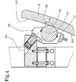
- Fig. 4 shows a detail of the sectional view of Fig. 3 , wherein in particular the region of the follower roller 11 is shown.
- the follower roller 11 rolls on the drum 9.
- the follower roller 11 contacts the drum 9 and in particular the inner jacket surface 20 of the drum 9 in a contact region 12.
- the contact region 12 is that region in which the follower roller 11 contacts the drum 9. Due to the pivotability of the follower roller 11, this contact region 12 has, for example, a curved course.
- the follower roller 11 is rotatably mounted on the trailing arm 18 about a wheel axis 17, which in the present representation is substantially projecting.
- the trailing link 18 is also rotatably or veschwenkbar arranged. In particular, the trailing link 18 is arranged rotatably about the steering axis 10.
- the follower roller is moved to a neutral position. This neutral position corresponds to a stable position of the trailing arm 18 and the follower roller 11.
- the trailing arm 18 is rotated about the steering axis 10.
- the parallelism of the two axes - drive roller and follower roller - is restored. As a result, tensions and high lateral forces, which would lead to wear, prevented.
Landscapes
- Life Sciences & Earth Sciences (AREA)
- Engineering & Computer Science (AREA)
- Food Science & Technology (AREA)
- Drying Of Solid Materials (AREA)
- Baking, Grill, Roasting (AREA)
- Medical Preparation Storing Or Oral Administration Devices (AREA)
- Rolls And Other Rotary Bodies (AREA)
- Tunnel Furnaces (AREA)
Description
- Die Erfindung betrifft eine Backvorrichtung zum Herstellen endloser Bänder aus vorzugsweise flüssigen Backmassen auf einem in einem Maschinengestell umlaufenden, zumindest abschnittsweise beheizten Backflächenträger, der zumindest eine endlose Backfläche durch zumindest eine im Maschinengestell stationär angeordnete, eine Heizvorrichtung enthaltende, von einer Backmassenauftragsvorrichtung bis zu einer Bandabnahmevorrichtung reichende Backzone transportiert, wobei eine drehbar gelagerte und angetriebene nabenlose Trommel als umlaufender beheizter Backflächenträger vorgesehen ist. Eine derartige Backvorrichtung ist aus der
WO97/34492 A1 - Beispielsweise sind Backmaschinen zur Herstellung gerollter Backprodukte wie Waffeln oder Hohlhippen bekannt, bei denen eine Trommel um eine zentrale Achse gedreht wird. Dabei ist die Trommel im Bereich der Achse mit einer Los-Festlageranordnung derart gelagert, dass eine seitliche Bewegung verhindert ist. Der Backflächenträger selbst ist radförmig oder zylinderförmig ausgeführt und weist Verbindungselemente auf, die von seinem Außenbereich bis zur Radnabe reichen. Diese Verbindung der äußeren Backfläche und der Radnabe hat den Nachteil, dass im Inneren des Backflächenträgers keine weiteren Elemente wie beispielsweise Heizelemente oder Backmassenauftragsvorrichtungen vorgesehen sein können.
- Aus diesem Grund wurden derartige Backmaschinen weiterentwickelt, wobei als Backflächenträger ein hohlzylinderförmiger Ring vorgesehen ist. Diese nabenlose Anordnung weist meist eine Antriebsrolle im unteren Bereich auf, auf welcher der Backring aufliegt. Die Backringe haben beispielsweise einen Durchmesser von etwa einem bis 2,5 Meter und eine Breite von etwa 20cm bis 60cm.
- Bei der Fertigung der Backringe sind eine exakte Planparallelität der seitlichen Stirnseiten sowie eine exakte Koaxialität der Rundflächen wirtschaftlich nicht fertigbar. Aufgrund der daraus resultierenden Fertigungstoleranzen neigen Backringe bei endloser Drehung dazu, eine seitliche Bewegung auszuführen. Um diese seitliche Bewegung des Backrings zu verhindern, werden gemäß Stand der Technik Führungsrollen mit Führungskränzen verwendet, deren Drehachsen im Wesentlichen parallel zur Drehachse des Backrings verlaufen. Nachteilig an dieser Konstruktion ist, dass es zwischen den Kränzen und dem Backring zu starkem Verschleiß kommt. Durch die relativ großen Abmaße und die langen Standzeiten kommt es bei dieser Zwangsführung zu Ausbrechen der Kanten des Backrings oder zum Bruch der Führungskränze der Führungsrollen.
- Aufgabe der Erfindung ist es eine Backvorrichtung oben genannter Art zu schaffen, bei der die nabenlose Trommel geführt ist, wobei die Führung einfach, verschleißarm, wartungsarm und zuverlässig ausgeführt ist.
- Insbesondere ist es eine Aufgabe der Erfindung, eine Antriebs- und Führungsvorrichtung für eine oben genannte Backmaschine zu schaffen, die einfach und effektiv im Aufbau ist, wobei dadurch die Wartungskosten und die Effizienz der Backmaschine verbessert ist.
- Die erfindungsgemäßen Aufgaben werden insbesondere durch die Merkmale der unabhängigen Patentansprüche gelöst.
- Weitere vorteilhafte Merkmale der Backvorrichtung zum Herstellen endloser Bänder aus vorzugsweise flüssigen Backmassen auf einem in einem Maschinengestell umlaufenden, zumindest abschnittsweise beheizten Backflächenträger, der zumindest eine endlose Backfläche durch zumindest eine im Maschinengestell stationär angeordnete, eine Heizvorrichtung enthaltende, von einer Backmassenauftragsvorrichtung bis zu einer Bandabnahmevorrichtung reichende Backzone transportiert, wobei eine drehbar gelagerte und angetriebene nabenlose Trommel als umlaufender beheizter Backflächenträger vorgesehen ist,
sind, dass eine um eine Lenkachse schwenkbar angeordnete Nachlaufrolle vorgesehen ist, die in einem Kontaktbereich an einer Abrollfläche der Trommel abrollt, wobei zwischen dem Schnittpunkt der Lenkachse mit der Abrollfläche und dem Kontaktbereich ein Nachlaufabstand vorgesehen ist, dass die Abrollfläche eine Mantelfläche der Trommel ist, dass die Abrollfläche eine innere Mantelfläche der Trommel ist, dass die Nachlaufrolle drehbar um eine Radachse an einem Nachlauflenker gelagert ist und/oder dass der Nachlauflenker drehbar um die Lenkachse am Maschinengestell gelagert ist. - In vorteilhafter Weise kann die Erfindung, dadurch gekennzeichnet sein, dass die Lenkachse im Wesentlichen orthogonal zur Radachse verläuft, dass die Trommel gegen die Schwerkraft an der Nachlaufrolle abgestützt ist, dass die Trommel hängend an einer Antriebsrolle zum Drehantrieb der Trommel angeordnet ist, dass die Trommel hohlzylinderförmig ausgeführt ist und eine innere Mantelfläche und eine äußere Mantelfläche umfasst, dass die Antriebsrolle und die Nachlaufrolle an der inneren Mantelfläche abrollen, dass eine Backfläche an der äußeren Mantelfläche vorgesehen ist und/oder dass bei Verschwenkung des Nachlauflenkers aus der neutralen Position, insbesondere durch die Drehung der Trommel ein Rückstellmoment Richtung neutrale Position erzeugt ist, wobei in der neutralen Position die Lenkachse und der Schwerpunkt des momentanen Berührbereichs der Nachlaufrolle mit der Abrollfläche in einer Ebene liegen, wobei die Ebene eine Normalebene der Drehachse der Trommel ist oder die Drehachse der Nachlaufrolle und die Drehachse der Antriebsrolle parallel verlaufen, dass beidseitig der Trommel jeweils zumindest eine Führungsrolle vorgesehen ist, dass die Führungsrollen die Trommel an deren Stirnseiten berühren oder im Bereich der Stirnseiten angeordnet sind, dass die Führungsrollen in einem Winkelbereich von 90° vor und/oder nach der Antriebsrolle vorgesehen sind und bevorzugt im oberen Drittel der an der Antriebsrolle hängenden Trommel vorgesehen sind, dass die Antriebsrolle außerhalb des oberen Wendepunkts an der Trommel anliegt und bevorzugt in einem Winkelbereich von 1° bis 30° vor oder nach dem oberen Wendepunkt der Trommel vorgesehen ist, dass die Trommel geometrisch eine erste Hälfte und eine zweite Hälfte umfasst, wobei die beiden Hälften durch eine vertikal verlaufende, die Drehachse der Trommel umfassende Ebene voneinander getrennt sind und/oder dass die Antriebsrolle die Trommel in der ersten Hälfte und die Nachlaufrolle die Trommel in der zweiten Hälfte außerhalb der Ebene berühren.
- Die Vorrichtung umfasst ein Maschinengestell, an welchem ein Backflächenträger vorgesehen ist. Dieser ist bevorzugt als hohlzylinderförmiger Körper ausgeführt, der durch eine stationär angeordnete Heizvorrichtung erwärmbar oder erwärmt ist, sodass zwischen einer Backmassenauftragsvorrichtung und einer Bandabnahmevorrichtung eine Backzone gebildet ist.
- Bevorzugt ist der Backflächenträger hängend an einer Antriebsrolle angeordnet und durch die Antriebsrolle rotatorisch angetrieben.
- In bevorzugter Weise ist die Antriebsrolle im oberen Bereich des Backflächenträgers vorgesehen. Der Backflächenträger, der insbesondere ringförmig ausgeführt ist, weist einen oberen Totpunkt auf. Der obere Totpunkt entspricht jenem Punkt des zylindrischen Körpers, der dem höchsten Punkt der aufrecht stehenden Trommel entspricht. Gemäß einer Ausführungsform der Erfindung ist die Antriebsrolle in einem Bereich außerhalb dieses oberen Totpunkts angeordnet. Insbesondere berührt die Antriebsrolle den Backflächenträger in einem Winkelbereich von etwa 1° bis 90° vor oder nach dem oberen Totpunkt.
- Um den Backflächenträger gegen die Schwerkraft in dieser Position zu halten, ist die erfindungsgemäße Nachlaufrolle vorgesehen. Diese ist mit dem Maschinengestell gekoppelt und an den Backflächenträger angelegt. Dadurch ist der Backflächenträger gegen die Schwerkraft an der Nachlaufrolle abgestützt.
- Die Nachlaufrolle ist drehbar um eine Radachse gelagert und rollt an einer Abrollfläche des Backflächenträgers ab. Insbesondere ist die Nachlaufrolle an einem Nachlauflenker drehbar gelagert. Der Nachlauflenker ist bevorzugt drehbar um eine Lenkachse gelagert, wobei bevorzugt die Lenkachse und die Radachse einen Normalabstand ungleich null zueinander aufweisen. Die Lenkachse liegt bevorzugt in einer Normalebene der Drehachse der Trommel.
- Die Nachlaufrolle berührt die Abrollfläche des Backflächenträgers in einem Kontaktbereich. Dieser Kontaktbereich ist jener Bereich, in dem ein Kontakt zwischen dem Backflächenträger und der Nachlaufrolle im Rahmen der Kinematik möglich ist. Durch ein Verschwenken der Nachlaufrolle entspricht der Kontaktbereich im Wesentlichen einem dreidimensional gekrümmten bogenförmigen Abschnitt. Die Nachlaufrolle hat eine stabile Lage in einem Mittelbereich, also in der neutralen Position. In der neutralen Position liegen z.B. die Lenkachse und der Schwerpunkt des momentanen Berührbereichs der Nachlaufrolle mit der Abrollfläche in einer Ebene, wobei die Ebene eine Normalebene der Drehachse der Trommel ist.
- Die Schnittachse der Lenkachse mit der Abrollfläche und der Kontaktbereich weisen einen gewissen Nachlaufabstand auf. Dadurch ist die Nachlaufrolle durch die Drehung des Backflächenträgers in die neutrale Position gedrückt. Insbesondere ist durch die Drehung des Backflächenträgers ein Rückstellmoment in die neutrale Position bewirkt. Dadurch ist eine Führung des Backflächenträgers bzw. der Trommel durch Selbstzentrierung bewirkt.
- Bevorzugt ist die Lenkachse im Wesentlichen orthogonal zur Drehachse der Nachlaufrolle angeordnet. Dies bedeutet, dass die beiden Drehachsen zueinander normal stehen. Dies bedeutet jedoch nicht zwangsläufig, dass die beiden Achsen einen Schnittpunkt miteinander aufweisen. Bevorzugt besteht kein Schnittpunkt.
- Als Abrollfläche wird jene Fläche des Backflächenträgers bezeichnet, an welcher die Nachlaufrolle abrollt. Dies kann eine Fläche, beispielsweise eine zylindrische Fläche sein. Jedoch können auch abschnittsweise segmentierte, gerippte oder ähnliche Flächen als Abrollflächen vorgesehen sein.
- Als Winkelbereich ist ein Bereich von Winkeln definiert, die vom Zentrum des Backflächenträgers in oder gegen die Rotation des Backflächenträgers gemessen werden.
- Ferner sind können zur seitlichen Führung der Trommel Führungsrollen vorgesehen sein. Diese sind insbesondere im Bereich der Antriebsrolle angeordnet und führen die Trommel im oberen Bereich. Bevorzugt sind die Führungsrollen derart angeordnet, dass sie zur Führung seitlich an der Stirnseite der Trommel abrollen. Sie sind dazu eingerichtet, eine stützende Korrektur des leichten, durch Fertigungstoleranzen hervorgerufenen seitlichen Verlaufens des Rings auszuführen.
- Die exakte Seitenführung wird durch die Nachlaufrolle ermöglicht.
- In weiterer Folge wird die Erfindung anhand konkreter Ausführungsbeispiele weiter beschrieben.
-
Fig. 1 zeigt eine Ansicht der Backvorrichtung von oben. -
Fig. 2 zeigt eine Schrägansicht der erfindungsgemäßen Backvorrichtung. -
Fig. 3 zeigt einen Schnitt der erfindungsgemäßen Backvorrichtung, wobei die Drehachse des Backflächenträgers im Wesentlichen projizierend verläuft. -
Fig. 4 zeigt ein Detail der Nachlaufrolle und des Nachlauflenkers in einer schematisierten Schnittdarstellung. -
Fig. 1 zeigt eine erfindungsgemäße Backvorrichtung von oben. Anzumerken ist, dass diese Darstellung eine schematische Darstellung ist. Die Vorrichtung umfasst ein Maschinengestell 2, einen Backflächenträger 3 mit einer Backfläche 4, auf der vier Bänder 1 gebacken werden. Der Backflächenträger 3 ist im Wesentlichen zylindrisch ausgestaltet, wobei die Drehachse dieses Zylinders in der Darstellung derFig. 1 im Wesentlichen in der Bildebene verläuft. Die Backmassenauftragsvorrichtung 6 sowie die Heizvorrichtung 5 sind in der vorliegenden schematischen Darstellung nicht eingezeichnet. Die Bandabnahmevorrichtung 7 ist dazu eingerichtet, die Bänder von dem Backflächenträger 3 bzw. der Backfläche 4 abzunehmen und weiter zu bearbeiten. Insbesondere kann eine Aufwicklung der Teigbänder 1 zu langgestreckten Röhren erfolgen. - Der Backflächenträger 3 ist in der vorliegenden Ausführungsform als Trommel 9 und insbesondere als nabenlose Trommel ausgeführt.
- Die Trommel 9 bzw. der Backflächenträger 3 sind drehbar angeordnet und angetrieben. Der Antrieb erfolgt in der vorliegenden Ausführungsform über die Antriebsrolle 19, die die Trommel 9 berührt. Die Antriebsrolle 19 ist von einem nicht dargestellten Drehantrieb angetrieben. Ferner sind seitlich an der Stirnseite 23 der Trommel 9 Führungsrollen 22 vorgesehen. Die Führungsrollen 22 sind mit dem Maschinengestell 2 verbunden und drehbar gelagert. Zwischen den jeweils paarweise angeordneten Rollen 22 besteht ein Freiraum, der im Wesentlichen der Breite des Backflächenträgers oder der Trommel 9 entspricht. Gegebenenfalls weist die so hergestellte seitliche Führung der Trommel 9 ein gewisses Übermaß auf, sodass die Druckkräfte und der Verschleiß zwischen der Stirnseite 23 der Trommel 9 und den Führungsrollen 22 klein gehalten sind. Gegebenenfalls können die Führungsrollen 22 auch gefedert gelagert sein. Die Drehachsen der Führungsrollen stehen im Wesentlichen normal auf die lokale Krümmung der Trommel im Berührberich. Beispielsweise sind die Drehachsen der Führungsrollen 22 in radialer Richtung zur Drehachse der Trommel 9 angeordnet. Die Führungsrollen 22 rollen an den Stirnseiten 23 der Trommel 9 ab.
- Die Bandabnahmevorrichtung entspricht einer herkömmlichen Bandabnahmevorrichtung.
-
Fig. 2 zeigt eine schematische Schrägansicht der erfindungsgemäßen Vorrichtung. Die Ansicht entspricht im Wesentlichen einer Ansicht von schräg unten. Die Vorrichtung umfasst ein Maschinengestell 2, einen Backflächenträger 3, der bevorzugt als Trommel 9 ausgeführt ist. Insbesondere ist die Trommel 9 nabenlos und/oder ringförmig ausgeführt. In der vorliegenden Ausführungsform entspricht die Form der Trommel 9 im Wesentlichen einem Hohlzylinder. Dieser hat eine zylindrische Außenfläche und eine zylindrische Innenfläche. Erfindungsgemäß sind eine innere Mantelfläche 20 sowie eine äußere Mantelfläche 21 vorgesehen. Drehbar und antreibbar ist die Antriebsrolle 19 mit dem Maschinengestell 2 gekoppelt. Die Antriebsrolle 19 ist über einen Drehantrieb antreibbar. Hängend an der Antriebsrolle 19 ist die Trommel 9 vorgesehen. Die Antriebsrolle 19 berührt die Trommel 9 an der inneren Mantelfläche 20. Ferner sind an den Stirnseiten 23 der Trommel 9 anliegend Führungsrollen 22 vorgesehen. In der schematischen Darstellung derFig. 2 sind seitliche Stützelemente des Maschinengestells 2 ausgeblendet, sodass die Vorrichtung übersichtlicher dargestellt ist. Insbesondere sind auch die Komponenten Backbandabnahmevorrichtung 7, Backmassenauftragsvorrichtung 6 sowie Heizvorrichtung 5 ausgeblendet. - Ferner ist eine Nachlaufrolle 11 vorgesehen. Diese Nachlaufrolle 11 rollt an der Trommel 9 ab, um insbesondere eine Stützung der Trommel zu bewirken. Dazu ist die Nachlaufrolle 11 an einem Nachlauflenker 18 vorgesehen. Der Nachlauflenker 18 und/oder die Nachlaufrolle 11 sind beweglich mit dem Maschinengestell 2 gekoppelt. Die Trommel weist eine Drehachse 27 auf, die bevorzugt ortsfest angeordnet ist. Jedoch ist der Bereich der Drehachse 27 im Wesentlichen frei von körperlichen Gegenständen. Wie obenstehend ausgeführt, handelt es sich bevorzugt um eine nabenlose Trommel 9.
-
Fig. 3 zeigt eine schematische Schnittdarstellung der erfindungsgemäßen Vorrichtung. - Schematisch sind die Komponenten Backmassenauftragsvorrichtung 6 sowie Bandabnahmevorrichtung 7 eingezeichnet. Die Backmassenauftragsvorrichtung 6 entspricht einer herkömmlichen Backmassenauftragsvorrichtung für Ringbackmaschinen. Diese ist dazu geeignet und/oder eingerichtet, die Backmasse bandförmig auf den beheizten Backflächenträger 3 bzw. auf die endlose Backfläche 4 aufzutragen. Die Drehrichtung des Backflächenträgers 3 bzw. der Trommel 9 verläuft in der Darstellung der
Fig. 3 im Uhrzeigersinn. Dies bedeutet, dass in der vorliegenden Konfiguration die Backzone 8 einen Großteil des Umfangs der Trommel einnimmt. Sie reicht insbesondere entlang der Drehrichtung der Trommel 9 von der Backmassenauftragsvorrichtung 6 bis zur Bandabnahmevorrichtung 7. Auch die Bandabnahmevorrichtung 7 ist in der vorliegenden Darstellung schematisch dargestellt und entspricht einer herkömmlichen Bandabnahmevorrichtung für Ringbackmaschinen -
Fig.3 stellt eine Möglichkeit der Positionierung der Backmassenauftragsvorrichtung 6 sowie der Bandabnahmevorrichtung 7 dar. Diese Komponenten können jedoch bei allen Ausführungsformen der Erfindung an anderen Positionen vorgesehen sein. Beispielsweise kann eine Backzone 8 an der Innenseite der Trommel vorgesehen sein. Dabei ist zu beachten, dass die Backzone nicht überschneidend mit jenen Komponenten angeordnet ist, die die Trommel an ihrer Innenseite berühren. Jedoch bietet die vorliegende Konfiguration zwischen den Komponenten Antriebsrolle 19 und Nachlaufrolle 11 ausreichend Platz, um an der Innenseite der Trommel eine Backzone zu bilden. - Ferner können gemäß einer weiteren alternativen Ausführungsform mehrere Backmassenauftragsvorrichtungen 6 nebeneinander vorgesehen sein, sodass auf einer Trommel 9 mehrere Bänder nebeneinander gebacken und durch eine oder mehrere Bandabnahmevorrichtung 7 abgenommen werden können.
- Ferner ist in
Fig. 3 schematisch die Heizvorrichtung 5 eingezeichnet. Auch diese entspricht im Wesentlichen einer herkömmlichen Heizvorrichtung für Ringbackmaschinen. Diese kann beispielsweise als Gasheizvorrichtung oder Induktionsheizvorrichtung ausgeführt sein. Insbesondere kann die Heizvorrichtung 5 an der Innenseite der Trommel, an der Außenseite der Trommel und/oder seitlich vorgesehen sein sowie sich über einen kleinen Teil sowie einen Großteil des Umfangs der Trommel erstrecken. Bevorzugt ist die Heizvorrichtung 5 entlang der Backzone 8 vorgesehen. - Die Trommel 9 ist hängend an der Antriebsrolle 19 vorgesehen. Zur Übertragung der Drehung berührt die Antriebsrolle 19 die Trommel 9. Der Berührbereich zwischen der Antriebsrolle 19 und der Trommel 9 ist bevorzugt außerhalb des oberen Wendepunktes 24 angeordnet. Dieser Wendepunkt 24 entspricht im Wesentlichen jenem Bereich der Trommel, in dem eine horizontal verlaufende, die Drehachse 27 des Backflächenträgers enthaltende Ebene 28 die Trommel 9 schneidet. Es handelt sich somit um den höchsten Punkt der Abrollfläche der Trommel 9. Die horizontale Ebene 28 teilt die Trommel 9 im Wesentlichen in zwei Hälften. Die erste Hälfte 25 ist in der vorliegenden Darstellung links der Ebene 28 angeordnet. Die zweite Hälfte 26 ist in der vorliegenden Darstellung rechts der Ebene 28 angeordnet. Die Antriebsrolle 19 berührt die Trommel 9 in der vorliegenden Ausführung in der ersten Hälfte 25. Ferner ist eine Nachlaufrolle 11 vorgesehen. Diese Nachlaufrolle 11 berührt die Trommel in der zweiten Hälfte 26. Wie angeführt verläuft die horizontale Ebene 28 im Wesentlichen durch die Drehachse 27 der Trommel 9, die in der vorliegenden Darstellung im Wesentlichen projizierend verläuft.
- Durch die außermittige Anordnung der Antriebsrolle 19 ist die Trommel 9 einerseits an der Antriebsrolle 19 und andererseits an der Nachlaufrolle 11 gegen die Schwerkraft abgestützt. Durch den außermittigen Versatz wird eine Kraft bewirkt, die die Trommel 9 selbsttätig durch Einfluss der Schwerkraft an die Nachlaufrolle 11 drückt. Durch die spezielle Ausgestaltung der Kinematik der Nachlaufrolle 11 ist eine selbsttätige Zentrierung der Trommel 9 bzw. des Backflächenträgers 3 bewirkt.
- In der vorliegenden Ausführungsform rollen die Antriebsrolle 19 sowie die Nachlaufrolle 11 an der inneren Mantelfläche 20 der Trommel 9 ab.
- Gegebenenfalls können die beiden Komponenten Nachlaufrolle 11 und Antriebsrolle 19 an unterschiedlichen Flächen der Trommel 9 abrollen. Beispielsweise können die Antriebsrolle und/oder die Nachlaufrolle auf der Außenseite bzw. auf der äußeren Mantelfläche 21 abrollen.
-
Fig. 4 zeigt ein Detail der Schnittdarstellung derFig. 3 , wobei insbesondere der Bereich der Nachlaufrolle 11 dargestellt ist. Die Nachlaufrolle 11 rollt an der Trommel 9 ab. - Insbesondere berührt die Nachlaufrolle 11 die Trommel 9 und insbesondere die innere Mantelfläche 20 der Trommel 9 in einem Kontaktbereich 12. Der Kontaktbereich 12 ist jener Bereich, in dem die Nachlaufrolle 11 die Trommel 9 berührt. Durch die Verschwenkbarkeit der Nachlaufrolle 11 hat dieser Kontaktbereich 12 beispielsweise einen bogenförmigen Verlauf. Die Nachlaufrolle 11 ist drehbar um eine Radachse 17, die in der vorliegenden Darstellung im Wesentlichen projizierend verläuft, an dem Nachlauflenker 18 angeordnet. Der Nachlauflenker 18 ist ebenfalls drehbar oder veschwenkbar angeordnet. Insbesondere ist der Nachlauflenker 18 um die Lenkachse 10 drehbar angeordnet. Die Abrollfläche 13, an welcher die Nachlaufrolle 11 abrollt und auf welcher der Kontaktbereich 12 vorgesehen ist, weist einen Abstand zum Schnittpunkt der Lenkachse 10 mit der Abrollfläche 13 auf. Dieser Abstand wird als Nachlaufabstand 16 bezeichnet. Durch Drehung der Trommel 9 ist die Nachlaufrolle in eine neutrale Position bewegt. Diese neutrale Position entspricht einer stabilen Lage des Nachlauflenkers 18 bzw. der Nachlaufrolle 11. Bei seitlicher Bewegung der Trommel 9 wird auch die Nachlaufrolle 11 mitbewegt, wodurch der Nachlauflenker 18 um die Lenkachse 10 verdreht wird. Die Parallelität der beiden Achsen - Antriebsrolle und Nachlaufrolle - ist wieder hergestellt. Dadurch sind Verspannungen und hohe Seitenverlaufskräfte, die zu Verschleiß führen würden, verhindert.
-
- 1
- Band
- 2
- Maschinengestell
- 3
- Backflächenträger
- 4
- Backfläche
- 5
- Heizvorrichtung
- 6
- Backmassenauftragsvorrichtung
- 7
- Bandabnahmevorrichtung
- 8
- Backzone
- 9
- Trommel
- 10
- Lenkachse
- 11
- Nachlaufrolle
- 12
- Kontaktbereich
- 13
- Abrollfläche
- 14
- Schnittpunkt
- 15
- -
- 16
- Nachlaufabstand
- 17
- Radachse
- 18
- Nachlauflenker
- 19
- Antriebsrolle
- 20
- Innere Mantelfläche
- 21
- Äußere Mantelfläche
- 22
- Führungsrolle
- 23
- Stirnseite
- 24
- Wendepunkt
- 25
- Erste Hälfte
- 26
- Zweite Hälfte
- 27
- Drehachse der Trommel
- 28
- Ebene
Claims (14)
- Backvorrichtung zum Herstellen endloser Bänder (1) aus vorzugsweise flüssigen Backmassen auf einem in einem Maschinengestell (2) umlaufenden, zumindest abschnittsweise beheizten Backflächenträger (3),
der zumindest eine endlose Backfläche (4) durch zumindest eine im Maschinengestell (2) stationär angeordnete, eine Heizvorrichtung (5) enthaltende, von einer Backmassenauftragsvorrichtung (6) bis zu einer Bandabnahmevorrichtung (7) reichende Backzone (8) transportiert,
wobei eine drehbar gelagerte und angetriebene nabenlose Trommel (9) als umlaufender beheizter Backflächenträger (3) vorgesehen ist,
dadurch gekennzeichnet, dass
eine um eine Lenkachse (10) schwenkbar angeordnete Nachlaufrolle (11) vorgesehen ist, die in einem Kontaktbereich (12) an einer Abrollfläche (13) der Trommel (9) abrollt, wobei zwischen dem Schnittpunkt (14) der Lenkachse (10) mit der Abrollfläche (13) und dem Kontaktbereich (12) ein Nachlaufabstand (16) vorgesehen ist. - Backvorrichtung nach Anspruch 1, dadurch gekennzeichnet, dass die Abrollfläche (13) eine Mantelfläche der Trommel (9) ist.
- Backvorrichtung nach Anspruch 1 oder 2, dadurch gekennzeichnet, dass die Abrollfläche (13) eine innere Mantelfläche (20) der Trommel (9) ist.
- Backvorrichtung nach einem der Ansprüche 1 bis 3, dadurch gekennzeichnet,
dass die Nachlaufrolle (11) drehbar um eine Radachse (17) an einem Nachlauflenker (18) gelagert ist und dass der Nachlauflenker (18) drehbar um die Lenkachse (10) am Maschinengestell gelagert ist. - Backvorrichtung nach Anspruch 4, dadurch gekennzeichnet, dass
die Lenkachse (10) im Wesentlichen orthogonal zur Radachse (17) verläuft. - Backvorrichtung nach einem der Ansprüche 1 bis 5, dadurch gekennzeichnet,
dass die Trommel (9) gegen die Schwerkraft an der Nachlaufrolle (11) abgestützt ist. - Backvorrichtung nach einem der Ansprüche 1 bis 6, dadurch gekennzeichnet,
dass die Trommel (9) hängend an einer Antriebsrolle (19) zum Drehantrieb der Trommel (9) angeordnet ist. - Backvorrichtung nach einem der Ansprüche 1 bis 7, dadurch gekennzeichnet,
dass die Trommel (9) hohlzylinderförmig ausgeführt ist und eine innere Mantelfläche (20) und eine äußere Mantelfläche (21) umfasst,
dass die Antriebsrolle (19) und die Nachlaufrolle (11) an der inneren Mantelfläche (20) abrollen und dass eine Backfläche (4) an der äußeren Mantelfläche (21) vorgesehen ist. - Backvorrichtung nach einem der Ansprüche 1 bis 8, dadurch gekennzeichnet,
dass bei Verschwenkung des Nachlauflenkers (18) aus der neutralen Position, insbesondere durch die Drehung der Trommel (9) ein Rückstellmoment Richtung neutrale Position erzeugt ist, wobei in der neutralen Position die Lenkachse (10) und der Schwerpunkt des momentanen Berührbereichs der Nachlaufrolle (11) mit der Abrollfläche (13) in einer Ebene liegen, wobei die Ebene eine Normalebene der Drehachse (27) der Trommel (9) ist. - Backvorrichtung nach einem der Ansprüche 1 bis 9, dadurch gekennzeichnet,
dass beidseitig der Trommel (9) jeweils zumindest eine Führungsrolle (22) vorgesehen ist. - Backvorrichtung nach Anspruche 10, dadurch gekennzeichnet, dass die Führungsrollen (22) die Trommel (9) an deren Stirnseiten (23) berühren oder im Bereich der Stirnseiten (23) angeordnet sind.
- Backvorrichtung nach einem der Ansprüche 10 oder 11, dadurch gekennzeichnet, dass die Führungsrollen in einem Winkelbereich von 90° vor und/oder nach der Antriebsrolle (19) vorgesehen sind und bevorzugt im oberen Drittel der an der Antriebsrolle (19) hängenden Trommel (9) vorgesehen sind.
- Backvorrichtung nach einem der Ansprüche 1 bis 12, dadurch gekennzeichnet,
dass die Antriebsrolle außerhalb des oberen Wendepunkts (24) an der Trommel (9) anliegt und bevorzugt in einem Winkelbereich von 1° bis 30° vor oder nach dem oberen Wendepunkt (24) der Trommel (9) vorgesehen ist. - Backvorrichtung nach einem der Ansprüche 1 bis 13, dadurch gekennzeichnet,
dass die Trommel (9) geometrisch eine erste Hälfte (25) und eine zweite Hälfte (26) umfasst, wobei die beiden Hälften (25, 26) durch eine vertikal verlaufende, die Drehachse (27) der Trommel (9) umfassende Ebene (28) voneinander getrennt sind und dass die Antriebsrolle (19) die Trommel (9) in der ersten Hälfte (25) und die Nachlaufrolle (11) die Trommel (9) in der zweiten Hälfte (26) außerhalb der Ebene (28) berühren.
Applications Claiming Priority (2)
| Application Number | Priority Date | Filing Date | Title |
|---|---|---|---|
| ATA684/2013A AT514571B1 (de) | 2013-09-03 | 2013-09-03 | Backvorrichtung |
| PCT/EP2014/068030 WO2015032649A1 (de) | 2013-09-03 | 2014-08-26 | Backvorrichtung |
Publications (2)
| Publication Number | Publication Date |
|---|---|
| EP3041358A1 EP3041358A1 (de) | 2016-07-13 |
| EP3041358B1 true EP3041358B1 (de) | 2017-10-25 |
Family
ID=51422073
Family Applications (1)
| Application Number | Title | Priority Date | Filing Date |
|---|---|---|---|
| EP14756037.9A Active EP3041358B1 (de) | 2013-09-03 | 2014-08-26 | Backvorrichtung |
Country Status (7)
| Country | Link |
|---|---|
| US (1) | US10499657B2 (de) |
| EP (1) | EP3041358B1 (de) |
| CN (1) | CN105555141B (de) |
| AT (1) | AT514571B1 (de) |
| RU (1) | RU2652142C2 (de) |
| TW (1) | TW201524359A (de) |
| WO (1) | WO2015032649A1 (de) |
Families Citing this family (5)
| Publication number | Priority date | Publication date | Assignee | Title |
|---|---|---|---|---|
| EP3272220B1 (de) | 2016-07-20 | 2019-10-09 | Haas Food Equipment GmbH | Backmaschine und wickelvorrichtung |
| EP3323291A1 (de) | 2016-11-22 | 2018-05-23 | Haas Food Equipment GmbH | Wickelvorrichtung und backmaschine |
| CN108432833A (zh) * | 2018-05-28 | 2018-08-24 | 宁阳县正邦食品机械有限公司 | 一种自动煎饼机用抓饼装置及煎饼机 |
| EP3721712A1 (de) * | 2019-04-12 | 2020-10-14 | Haas Food Equipment GmbH | Backvorrichtung und produktionsanlage |
| EP3915381A1 (de) | 2020-05-29 | 2021-12-01 | Bühler Food Equipment GmbH | Übergabevorrichtung zur übergabe von gebackenen waffelröllchen |
Family Cites Families (9)
| Publication number | Priority date | Publication date | Assignee | Title |
|---|---|---|---|---|
| CN2031202U (zh) * | 1988-01-30 | 1989-01-25 | 北京市商业机械研究所 | 一种糕点成型机 |
| CN2055323U (zh) * | 1989-06-15 | 1990-04-04 | 陈再安 | 糕饼自动烘焙炉 |
| US5575083A (en) * | 1993-07-05 | 1996-11-19 | Goldstar Co., Ltd. | Vacuum dryer |
| AT413177B (de) * | 1996-03-18 | 2005-12-15 | Haas Franz Waffelmasch | Backvorrichtung zum herstellen von endlosen bändern |
| TW391867B (en) * | 1997-11-17 | 2000-06-01 | Heden Team Ag | Automatic baking apparatus and mixbag thereof |
| AT411955B (de) * | 1999-05-04 | 2004-08-26 | Haas Franz Waffelmasch | Backvorrichtung zum herstellen von endlosen bändern |
| US20020155803A1 (en) | 2001-04-18 | 2002-10-24 | Tieleman Rudolf J. | Poultry processing machine having carcass locating apparatus |
| AT506740B1 (de) * | 2008-04-16 | 2010-07-15 | Haas Franz Waffel & Keksanlagen Industrie Gmbh | Anlage zum herstellen von sandwichkeksen und dergleichen |
| RU121996U1 (ru) * | 2012-07-13 | 2012-11-20 | Общество С Ограниченной Ответственностью "Фудлайн" | Установка для выпекания блинов |
-
2013
- 2013-09-03 AT ATA684/2013A patent/AT514571B1/de not_active IP Right Cessation
-
2014
- 2014-08-25 TW TW103129160A patent/TW201524359A/zh unknown
- 2014-08-26 RU RU2016112086A patent/RU2652142C2/ru active
- 2014-08-26 EP EP14756037.9A patent/EP3041358B1/de active Active
- 2014-08-26 CN CN201480048677.0A patent/CN105555141B/zh not_active Expired - Fee Related
- 2014-08-26 WO PCT/EP2014/068030 patent/WO2015032649A1/de not_active Ceased
- 2014-08-26 US US14/916,337 patent/US10499657B2/en not_active Expired - Fee Related
Non-Patent Citations (1)
| Title |
|---|
| None * |
Also Published As
| Publication number | Publication date |
|---|---|
| CN105555141B (zh) | 2017-10-17 |
| TW201524359A (zh) | 2015-07-01 |
| EP3041358A1 (de) | 2016-07-13 |
| WO2015032649A1 (de) | 2015-03-12 |
| RU2016112086A (ru) | 2017-10-09 |
| AT514571B1 (de) | 2015-02-15 |
| CN105555141A (zh) | 2016-05-04 |
| RU2652142C2 (ru) | 2018-04-25 |
| US10499657B2 (en) | 2019-12-10 |
| AT514571A4 (de) | 2015-02-15 |
| US20160192663A1 (en) | 2016-07-07 |
Similar Documents
| Publication | Publication Date | Title |
|---|---|---|
| DE3406719C2 (de) | ||
| DE60114777T2 (de) | Vorrichtung zur übergabe von behältern mit einem führungsrad variabler geometrie | |
| DE3248788C2 (de) | Vorrichtung zum Drehen eines Gegenstandes um einen gegebenen Winkel um eine vertikale Achse | |
| DE2806959C2 (de) | Traganordnung für große zylindrische Lasteinheiten, insbesondere Großrohre | |
| EP3773389B1 (de) | Vorrichtung zur formung von tampons | |
| AT514571B1 (de) | Backvorrichtung | |
| DE2139159B2 (de) | Vorrichtung zum Breitstrecken von Warenbahnen, insbesondere von Papierbahnen | |
| EP0408996B1 (de) | Abzugsvorrichtung für Schlauchbahnen aus Kunststoffolie | |
| WO2012152416A2 (de) | Vorrichtung zum umsetzen von fahrzeugrädern | |
| EP2808477A1 (de) | Vorrichtung zum Zusammenbau von Isolierglasscheiben | |
| DE2632505A1 (de) | Materialflussteiler fuer ein transportbahnsystem | |
| EP0694019B1 (de) | Vorrichtung zum ablösen eines produktes von einem endlos umlaufenden band | |
| DE2947438A1 (de) | Vorrichtung zum querabtrennen beleimter verbindungsblaettchen zum umhuellen von zigaretten-mundstueck-gruppen von einem belagpierstreifen der tabakverarbeitenden industrie | |
| EP2750816A1 (de) | Fertigungsanlage zur herstellung von produkten aus zylindrischen metallstäben | |
| DE3511883C1 (de) | Maschine zum Schweissen von Längsnähten an gerundeten Blechgebinde-Zargen | |
| WO2013189792A1 (de) | Bandumlenkvorrichtung | |
| DE10158426A1 (de) | Vorrichtung zum Sortieren von flächigen Stückgütern | |
| DE1602449A1 (de) | Vorrichtung zum selbsttaetigen Schneiden und Vorboerdeln zylindrischer Koerper,insbesondere fuer Konservendosen | |
| DE3310622A1 (de) | Vorrichtung zur umwandlung einer kontinuierlichen drehbewegung einer antriebswelle in eine intermittierende drehbewegung einer angetriebene welle | |
| DE2430633C3 (de) | Vorrichtung zum Drehen von nicht rotationssymmetrischen Körpern | |
| DE19654857A1 (de) | Vorrichtung zum Trennen und seitlichem Auslenken durch Längsschnitt erzeugten Metallstreifen | |
| EP0032736A2 (de) | Verfahren und Vorrichting zur Herstellung von bewickelten Ringen | |
| EP0406988B1 (de) | Prägekalander | |
| EP2601120B1 (de) | Vorrichtung zum aufwickeln von bahnförmigen materialien zu rollen | |
| DE1811754C3 (de) | Breitstreckvorrichtung für Schlauchware |
Legal Events
| Date | Code | Title | Description |
|---|---|---|---|
| PUAI | Public reference made under article 153(3) epc to a published international application that has entered the european phase |
Free format text: ORIGINAL CODE: 0009012 |
|
| 17P | Request for examination filed |
Effective date: 20160222 |
|
| AK | Designated contracting states |
Kind code of ref document: A1 Designated state(s): AL AT BE BG CH CY CZ DE DK EE ES FI FR GB GR HR HU IE IS IT LI LT LU LV MC MK MT NL NO PL PT RO RS SE SI SK SM TR |
|
| AX | Request for extension of the european patent |
Extension state: BA ME |
|
| DAX | Request for extension of the european patent (deleted) | ||
| REG | Reference to a national code |
Ref country code: DE Ref legal event code: R079 Ref document number: 502014005979 Country of ref document: DE Free format text: PREVIOUS MAIN CLASS: A21B0005020000 Ipc: A21B0001480000 |
|
| RIC1 | Information provided on ipc code assigned before grant |
Ipc: A21B 5/02 20060101ALI20170403BHEP Ipc: A21B 1/48 20060101AFI20170403BHEP |
|
| GRAP | Despatch of communication of intention to grant a patent |
Free format text: ORIGINAL CODE: EPIDOSNIGR1 |
|
| INTG | Intention to grant announced |
Effective date: 20170517 |
|
| GRAS | Grant fee paid |
Free format text: ORIGINAL CODE: EPIDOSNIGR3 |
|
| GRAA | (expected) grant |
Free format text: ORIGINAL CODE: 0009210 |
|
| AK | Designated contracting states |
Kind code of ref document: B1 Designated state(s): AL AT BE BG CH CY CZ DE DK EE ES FI FR GB GR HR HU IE IS IT LI LT LU LV MC MK MT NL NO PL PT RO RS SE SI SK SM TR |
|
| REG | Reference to a national code |
Ref country code: GB Ref legal event code: FG4D Free format text: NOT ENGLISH |
|
| REG | Reference to a national code |
Ref country code: CH Ref legal event code: EP |
|
| REG | Reference to a national code |
Ref country code: AT Ref legal event code: REF Ref document number: 939000 Country of ref document: AT Kind code of ref document: T Effective date: 20171115 |
|
| REG | Reference to a national code |
Ref country code: IE Ref legal event code: FG4D Free format text: LANGUAGE OF EP DOCUMENT: GERMAN |
|
| REG | Reference to a national code |
Ref country code: DE Ref legal event code: R096 Ref document number: 502014005979 Country of ref document: DE |
|
| REG | Reference to a national code |
Ref country code: NL Ref legal event code: MP Effective date: 20171025 |
|
| REG | Reference to a national code |
Ref country code: LT Ref legal event code: MG4D |
|
| PG25 | Lapsed in a contracting state [announced via postgrant information from national office to epo] |
Ref country code: NL Free format text: LAPSE BECAUSE OF FAILURE TO SUBMIT A TRANSLATION OF THE DESCRIPTION OR TO PAY THE FEE WITHIN THE PRESCRIBED TIME-LIMIT Effective date: 20171025 |
|
| PG25 | Lapsed in a contracting state [announced via postgrant information from national office to epo] |
Ref country code: SE Free format text: LAPSE BECAUSE OF FAILURE TO SUBMIT A TRANSLATION OF THE DESCRIPTION OR TO PAY THE FEE WITHIN THE PRESCRIBED TIME-LIMIT Effective date: 20171025 Ref country code: FI Free format text: LAPSE BECAUSE OF FAILURE TO SUBMIT A TRANSLATION OF THE DESCRIPTION OR TO PAY THE FEE WITHIN THE PRESCRIBED TIME-LIMIT Effective date: 20171025 Ref country code: NO Free format text: LAPSE BECAUSE OF FAILURE TO SUBMIT A TRANSLATION OF THE DESCRIPTION OR TO PAY THE FEE WITHIN THE PRESCRIBED TIME-LIMIT Effective date: 20180125 Ref country code: ES Free format text: LAPSE BECAUSE OF FAILURE TO SUBMIT A TRANSLATION OF THE DESCRIPTION OR TO PAY THE FEE WITHIN THE PRESCRIBED TIME-LIMIT Effective date: 20171025 Ref country code: LT Free format text: LAPSE BECAUSE OF FAILURE TO SUBMIT A TRANSLATION OF THE DESCRIPTION OR TO PAY THE FEE WITHIN THE PRESCRIBED TIME-LIMIT Effective date: 20171025 |
|
| PG25 | Lapsed in a contracting state [announced via postgrant information from national office to epo] |
Ref country code: HR Free format text: LAPSE BECAUSE OF FAILURE TO SUBMIT A TRANSLATION OF THE DESCRIPTION OR TO PAY THE FEE WITHIN THE PRESCRIBED TIME-LIMIT Effective date: 20171025 Ref country code: IS Free format text: LAPSE BECAUSE OF FAILURE TO SUBMIT A TRANSLATION OF THE DESCRIPTION OR TO PAY THE FEE WITHIN THE PRESCRIBED TIME-LIMIT Effective date: 20180225 Ref country code: RS Free format text: LAPSE BECAUSE OF FAILURE TO SUBMIT A TRANSLATION OF THE DESCRIPTION OR TO PAY THE FEE WITHIN THE PRESCRIBED TIME-LIMIT Effective date: 20171025 Ref country code: BG Free format text: LAPSE BECAUSE OF FAILURE TO SUBMIT A TRANSLATION OF THE DESCRIPTION OR TO PAY THE FEE WITHIN THE PRESCRIBED TIME-LIMIT Effective date: 20180125 Ref country code: LV Free format text: LAPSE BECAUSE OF FAILURE TO SUBMIT A TRANSLATION OF THE DESCRIPTION OR TO PAY THE FEE WITHIN THE PRESCRIBED TIME-LIMIT Effective date: 20171025 Ref country code: GR Free format text: LAPSE BECAUSE OF FAILURE TO SUBMIT A TRANSLATION OF THE DESCRIPTION OR TO PAY THE FEE WITHIN THE PRESCRIBED TIME-LIMIT Effective date: 20180126 |
|
| REG | Reference to a national code |
Ref country code: DE Ref legal event code: R097 Ref document number: 502014005979 Country of ref document: DE |
|
| PG25 | Lapsed in a contracting state [announced via postgrant information from national office to epo] |
Ref country code: EE Free format text: LAPSE BECAUSE OF FAILURE TO SUBMIT A TRANSLATION OF THE DESCRIPTION OR TO PAY THE FEE WITHIN THE PRESCRIBED TIME-LIMIT Effective date: 20171025 Ref country code: CY Free format text: LAPSE BECAUSE OF FAILURE TO SUBMIT A TRANSLATION OF THE DESCRIPTION OR TO PAY THE FEE WITHIN THE PRESCRIBED TIME-LIMIT Effective date: 20171025 Ref country code: CZ Free format text: LAPSE BECAUSE OF FAILURE TO SUBMIT A TRANSLATION OF THE DESCRIPTION OR TO PAY THE FEE WITHIN THE PRESCRIBED TIME-LIMIT Effective date: 20171025 Ref country code: SK Free format text: LAPSE BECAUSE OF FAILURE TO SUBMIT A TRANSLATION OF THE DESCRIPTION OR TO PAY THE FEE WITHIN THE PRESCRIBED TIME-LIMIT Effective date: 20171025 Ref country code: DK Free format text: LAPSE BECAUSE OF FAILURE TO SUBMIT A TRANSLATION OF THE DESCRIPTION OR TO PAY THE FEE WITHIN THE PRESCRIBED TIME-LIMIT Effective date: 20171025 |
|
| PG25 | Lapsed in a contracting state [announced via postgrant information from national office to epo] |
Ref country code: PL Free format text: LAPSE BECAUSE OF FAILURE TO SUBMIT A TRANSLATION OF THE DESCRIPTION OR TO PAY THE FEE WITHIN THE PRESCRIBED TIME-LIMIT Effective date: 20171025 Ref country code: IT Free format text: LAPSE BECAUSE OF FAILURE TO SUBMIT A TRANSLATION OF THE DESCRIPTION OR TO PAY THE FEE WITHIN THE PRESCRIBED TIME-LIMIT Effective date: 20171025 Ref country code: RO Free format text: LAPSE BECAUSE OF FAILURE TO SUBMIT A TRANSLATION OF THE DESCRIPTION OR TO PAY THE FEE WITHIN THE PRESCRIBED TIME-LIMIT Effective date: 20171025 Ref country code: SM Free format text: LAPSE BECAUSE OF FAILURE TO SUBMIT A TRANSLATION OF THE DESCRIPTION OR TO PAY THE FEE WITHIN THE PRESCRIBED TIME-LIMIT Effective date: 20171025 |
|
| PLBE | No opposition filed within time limit |
Free format text: ORIGINAL CODE: 0009261 |
|
| STAA | Information on the status of an ep patent application or granted ep patent |
Free format text: STATUS: NO OPPOSITION FILED WITHIN TIME LIMIT |
|
| PG25 | Lapsed in a contracting state [announced via postgrant information from national office to epo] |
Ref country code: MT Free format text: LAPSE BECAUSE OF FAILURE TO SUBMIT A TRANSLATION OF THE DESCRIPTION OR TO PAY THE FEE WITHIN THE PRESCRIBED TIME-LIMIT Effective date: 20171025 |
|
| 26N | No opposition filed |
Effective date: 20180726 |
|
| PG25 | Lapsed in a contracting state [announced via postgrant information from national office to epo] |
Ref country code: SI Free format text: LAPSE BECAUSE OF FAILURE TO SUBMIT A TRANSLATION OF THE DESCRIPTION OR TO PAY THE FEE WITHIN THE PRESCRIBED TIME-LIMIT Effective date: 20171025 |
|
| PG25 | Lapsed in a contracting state [announced via postgrant information from national office to epo] |
Ref country code: MC Free format text: LAPSE BECAUSE OF FAILURE TO SUBMIT A TRANSLATION OF THE DESCRIPTION OR TO PAY THE FEE WITHIN THE PRESCRIBED TIME-LIMIT Effective date: 20171025 |
|
| REG | Reference to a national code |
Ref country code: CH Ref legal event code: PL |
|
| GBPC | Gb: european patent ceased through non-payment of renewal fee |
Effective date: 20180826 |
|
| PG25 | Lapsed in a contracting state [announced via postgrant information from national office to epo] |
Ref country code: LU Free format text: LAPSE BECAUSE OF NON-PAYMENT OF DUE FEES Effective date: 20180826 Ref country code: LI Free format text: LAPSE BECAUSE OF NON-PAYMENT OF DUE FEES Effective date: 20180831 Ref country code: CH Free format text: LAPSE BECAUSE OF NON-PAYMENT OF DUE FEES Effective date: 20180831 |
|
| REG | Reference to a national code |
Ref country code: BE Ref legal event code: MM Effective date: 20180831 |
|
| PG25 | Lapsed in a contracting state [announced via postgrant information from national office to epo] |
Ref country code: BE Free format text: LAPSE BECAUSE OF NON-PAYMENT OF DUE FEES Effective date: 20180831 Ref country code: FR Free format text: LAPSE BECAUSE OF NON-PAYMENT OF DUE FEES Effective date: 20180831 |
|
| PG25 | Lapsed in a contracting state [announced via postgrant information from national office to epo] |
Ref country code: GB Free format text: LAPSE BECAUSE OF NON-PAYMENT OF DUE FEES Effective date: 20180826 |
|
| PG25 | Lapsed in a contracting state [announced via postgrant information from national office to epo] |
Ref country code: PT Free format text: LAPSE BECAUSE OF FAILURE TO SUBMIT A TRANSLATION OF THE DESCRIPTION OR TO PAY THE FEE WITHIN THE PRESCRIBED TIME-LIMIT Effective date: 20171025 |
|
| PG25 | Lapsed in a contracting state [announced via postgrant information from national office to epo] |
Ref country code: IE Free format text: LAPSE BECAUSE OF NON-PAYMENT OF DUE FEES Effective date: 20180826 Ref country code: HU Free format text: LAPSE BECAUSE OF FAILURE TO SUBMIT A TRANSLATION OF THE DESCRIPTION OR TO PAY THE FEE WITHIN THE PRESCRIBED TIME-LIMIT; INVALID AB INITIO Effective date: 20140826 Ref country code: MK Free format text: LAPSE BECAUSE OF NON-PAYMENT OF DUE FEES Effective date: 20171025 |
|
| PG25 | Lapsed in a contracting state [announced via postgrant information from national office to epo] |
Ref country code: AL Free format text: LAPSE BECAUSE OF FAILURE TO SUBMIT A TRANSLATION OF THE DESCRIPTION OR TO PAY THE FEE WITHIN THE PRESCRIBED TIME-LIMIT Effective date: 20171025 |
|
| PGFP | Annual fee paid to national office [announced via postgrant information from national office to epo] |
Ref country code: DE Payment date: 20200824 Year of fee payment: 7 Ref country code: TR Payment date: 20200825 Year of fee payment: 7 |
|
| PGFP | Annual fee paid to national office [announced via postgrant information from national office to epo] |
Ref country code: AT Payment date: 20200819 Year of fee payment: 7 |
|
| REG | Reference to a national code |
Ref country code: DE Ref legal event code: R119 Ref document number: 502014005979 Country of ref document: DE |
|
| REG | Reference to a national code |
Ref country code: AT Ref legal event code: MM01 Ref document number: 939000 Country of ref document: AT Kind code of ref document: T Effective date: 20210826 |
|
| PG25 | Lapsed in a contracting state [announced via postgrant information from national office to epo] |
Ref country code: AT Free format text: LAPSE BECAUSE OF NON-PAYMENT OF DUE FEES Effective date: 20210826 |
|
| PG25 | Lapsed in a contracting state [announced via postgrant information from national office to epo] |
Ref country code: DE Free format text: LAPSE BECAUSE OF NON-PAYMENT OF DUE FEES Effective date: 20220301 |