EP3041104B1 - Dc power generation system and protection method for dc power generation system - Google Patents
Dc power generation system and protection method for dc power generation system Download PDFInfo
- Publication number
- EP3041104B1 EP3041104B1 EP14840613.5A EP14840613A EP3041104B1 EP 3041104 B1 EP3041104 B1 EP 3041104B1 EP 14840613 A EP14840613 A EP 14840613A EP 3041104 B1 EP3041104 B1 EP 3041104B1
- Authority
- EP
- European Patent Office
- Prior art keywords
- arc
- voltage
- string
- current
- power generation
- Prior art date
- Legal status (The legal status is an assumption and is not a legal conclusion. Google has not performed a legal analysis and makes no representation as to the accuracy of the status listed.)
- Active
Links
- 238000010248 power generation Methods 0.000 title claims description 72
- 238000000034 method Methods 0.000 title claims description 14
- 230000002265 prevention Effects 0.000 claims description 13
- 238000001514 detection method Methods 0.000 claims description 6
- 230000007423 decrease Effects 0.000 description 15
- 238000010586 diagram Methods 0.000 description 11
- 230000002159 abnormal effect Effects 0.000 description 2
- 230000005856 abnormality Effects 0.000 description 2
- 238000010276 construction Methods 0.000 description 2
- 241001465754 Metazoa Species 0.000 description 1
- 230000015556 catabolic process Effects 0.000 description 1
- 239000004020 conductor Substances 0.000 description 1
- 230000003247 decreasing effect Effects 0.000 description 1
- 238000006731 degradation reaction Methods 0.000 description 1
- 230000006866 deterioration Effects 0.000 description 1
- 238000011161 development Methods 0.000 description 1
- 230000018109 developmental process Effects 0.000 description 1
- 238000009434 installation Methods 0.000 description 1
- 239000012212 insulator Substances 0.000 description 1
- 239000002184 metal Substances 0.000 description 1
- 150000003839 salts Chemical class 0.000 description 1
Images


Classifications
-
- H—ELECTRICITY
- H02—GENERATION; CONVERSION OR DISTRIBUTION OF ELECTRIC POWER
- H02H—EMERGENCY PROTECTIVE CIRCUIT ARRANGEMENTS
- H02H1/00—Details of emergency protective circuit arrangements
- H02H1/0007—Details of emergency protective circuit arrangements concerning the detecting means
- H02H1/0015—Using arc detectors
-
- H—ELECTRICITY
- H02—GENERATION; CONVERSION OR DISTRIBUTION OF ELECTRIC POWER
- H02H—EMERGENCY PROTECTIVE CIRCUIT ARRANGEMENTS
- H02H3/00—Emergency protective circuit arrangements for automatic disconnection directly responsive to an undesired change from normal electric working condition with or without subsequent reconnection ; integrated protection
- H02H3/38—Emergency protective circuit arrangements for automatic disconnection directly responsive to an undesired change from normal electric working condition with or without subsequent reconnection ; integrated protection responsive to both voltage and current; responsive to phase angle between voltage and current
-
- H—ELECTRICITY
- H02—GENERATION; CONVERSION OR DISTRIBUTION OF ELECTRIC POWER
- H02H—EMERGENCY PROTECTIVE CIRCUIT ARRANGEMENTS
- H02H7/00—Emergency protective circuit arrangements specially adapted for specific types of electric machines or apparatus or for sectionalised protection of cable or line systems, and effecting automatic switching in the event of an undesired change from normal working conditions
- H02H7/20—Emergency protective circuit arrangements specially adapted for specific types of electric machines or apparatus or for sectionalised protection of cable or line systems, and effecting automatic switching in the event of an undesired change from normal working conditions for electronic equipment
-
- H—ELECTRICITY
- H02—GENERATION; CONVERSION OR DISTRIBUTION OF ELECTRIC POWER
- H02M—APPARATUS FOR CONVERSION BETWEEN AC AND AC, BETWEEN AC AND DC, OR BETWEEN DC AND DC, AND FOR USE WITH MAINS OR SIMILAR POWER SUPPLY SYSTEMS; CONVERSION OF DC OR AC INPUT POWER INTO SURGE OUTPUT POWER; CONTROL OR REGULATION THEREOF
- H02M7/00—Conversion of ac power input into dc power output; Conversion of dc power input into ac power output
- H02M7/42—Conversion of dc power input into ac power output without possibility of reversal
- H02M7/44—Conversion of dc power input into ac power output without possibility of reversal by static converters
-
- H—ELECTRICITY
- H02—GENERATION; CONVERSION OR DISTRIBUTION OF ELECTRIC POWER
- H02S—GENERATION OF ELECTRIC POWER BY CONVERSION OF INFRARED RADIATION, VISIBLE LIGHT OR ULTRAVIOLET LIGHT, e.g. USING PHOTOVOLTAIC [PV] MODULES
- H02S50/00—Monitoring or testing of PV systems, e.g. load balancing or fault identification
-
- G—PHYSICS
- G01—MEASURING; TESTING
- G01R—MEASURING ELECTRIC VARIABLES; MEASURING MAGNETIC VARIABLES
- G01R31/00—Arrangements for testing electric properties; Arrangements for locating electric faults; Arrangements for electrical testing characterised by what is being tested not provided for elsewhere
- G01R31/08—Locating faults in cables, transmission lines, or networks
-
- G—PHYSICS
- G01—MEASURING; TESTING
- G01R—MEASURING ELECTRIC VARIABLES; MEASURING MAGNETIC VARIABLES
- G01R31/00—Arrangements for testing electric properties; Arrangements for locating electric faults; Arrangements for electrical testing characterised by what is being tested not provided for elsewhere
- G01R31/12—Testing dielectric strength or breakdown voltage ; Testing or monitoring effectiveness or level of insulation, e.g. of a cable or of an apparatus, for example using partial discharge measurements; Electrostatic testing
- G01R31/1227—Testing dielectric strength or breakdown voltage ; Testing or monitoring effectiveness or level of insulation, e.g. of a cable or of an apparatus, for example using partial discharge measurements; Electrostatic testing of components, parts or materials
-
- G—PHYSICS
- G01—MEASURING; TESTING
- G01R—MEASURING ELECTRIC VARIABLES; MEASURING MAGNETIC VARIABLES
- G01R31/00—Arrangements for testing electric properties; Arrangements for locating electric faults; Arrangements for electrical testing characterised by what is being tested not provided for elsewhere
- G01R31/50—Testing of electric apparatus, lines, cables or components for short-circuits, continuity, leakage current or incorrect line connections
- G01R31/52—Testing for short-circuits, leakage current or ground faults
-
- H—ELECTRICITY
- H02—GENERATION; CONVERSION OR DISTRIBUTION OF ELECTRIC POWER
- H02H—EMERGENCY PROTECTIVE CIRCUIT ARRANGEMENTS
- H02H7/00—Emergency protective circuit arrangements specially adapted for specific types of electric machines or apparatus or for sectionalised protection of cable or line systems, and effecting automatic switching in the event of an undesired change from normal working conditions
- H02H7/26—Sectionalised protection of cable or line systems, e.g. for disconnecting a section on which a short-circuit, earth fault, or arc discharge has occured
- H02H7/268—Sectionalised protection of cable or line systems, e.g. for disconnecting a section on which a short-circuit, earth fault, or arc discharge has occured for dc systems
-
- Y—GENERAL TAGGING OF NEW TECHNOLOGICAL DEVELOPMENTS; GENERAL TAGGING OF CROSS-SECTIONAL TECHNOLOGIES SPANNING OVER SEVERAL SECTIONS OF THE IPC; TECHNICAL SUBJECTS COVERED BY FORMER USPC CROSS-REFERENCE ART COLLECTIONS [XRACs] AND DIGESTS
- Y02—TECHNOLOGIES OR APPLICATIONS FOR MITIGATION OR ADAPTATION AGAINST CLIMATE CHANGE
- Y02E—REDUCTION OF GREENHOUSE GAS [GHG] EMISSIONS, RELATED TO ENERGY GENERATION, TRANSMISSION OR DISTRIBUTION
- Y02E10/00—Energy generation through renewable energy sources
- Y02E10/50—Photovoltaic [PV] energy
- Y02E10/56—Power conversion systems, e.g. maximum power point trackers
Definitions
- This invention relates to detection of a parallel arc or a series arc in a DC power generation system, and protection against occurrence of an arc.
- Patent Documents 1 to 3 Arc fault detection and protection of solar power generation system is disclosed in Patent Documents 1 to 3, for example.
- Patent Document 1 a difference between power which is supplied to a load and power which is generated by photovoltaic panels is obtained, and in a case where a difference of the power is larger than a threshold value, an alarm condition is set.
- noise voltage of a load and noise voltage of photovoltaic panels are measured and a difference of the voltage is obtained, and in a case where a difference of the noise voltages is larger than a threshold value, an alarm condition is set. In a case where a difference between power which is generated by photovoltaic panels and power of a load is larger than a threshold value, an alarm condition is set.
- an arc detector is provided at an end part of a power line and on a retrace line, and an overcurrent protection, an arc failure protection and a reverse-current protection can be performed.
- an arc detection is performed only by parallel arc judgement with a reverse-current detector.
- Patent Document 4 is considered as the relevant background art and discloses a method for detecting arcs in a direct-current path of a photovoltaic system, wherein values of a current of the direct-current path are detected during a repeating time frame and a mean value is generated.
- a mega solar system as a DC power generation system is a huge system, therefore, in a case where an arc fault occurs, it is difficult to specify a point where an arc failure occurs. Further, a short circuit current is determined by a voltage-current characteristic of a solar panel. Therefore, even when an arc fault occurs, a switch does not operate. Consequently, it is necessary to separate only a fault section and realize to continue operation in a sound section.
- this invention aims to provide a DC power generation system whose protection performance against occurrence of an arc is improved by judging an arc occurrence point and an arc mode.
- the problem is solved by means of a DC power generation system as defined in independent claim 1 and a protection method for a DC power generation system defined in independent claim 8.
- Advantageous further developments of the DC generation system according to the invention are set forth in the subclaims.
- an arc occurrence point and an arc mode can be specified and only arc fault section can be separated.
- FIG. 1 is a circuit diagram showing a schematic configuration of a DC power generation system according to Embodiment 1 of this invention.
- a string A comprises a plurality of DC power generation modules 1A which are connected in series and the string A is connected to a DC bus 20 via a switch 2A.
- a string B comprises a plurality of DC power generation modules 1B which are connected in series
- a string C comprises a plurality of DC power generation modules 1C which are connected in series
- the string B and the string C are connected to the DC bus 20 via a switch 2B or 2C, respectively.
- FIG. 1 In the vicinity of the switch 2 (2A, 2B, 2C...), a voltage-current sensor 3 (3A, 3B, 3C%) is arranged, an arc detector 100 (100A, 100B, 100C%) which detects an arc by inputting an output of the voltage-current sensor 3 is attached to each circuit.
- DC buses further merge at a side of a power conditioner 4.
- DC power which is generated by the DC power generation module 1 (1A, 1B, 1C) is converted to AC power of commercial frequency by the power conditioner 4 and is applied to customers such as an ordinary home and a factory via commercial power network.
- a solar power generation system in which a solar power generation module (also refers to a solar power panel) 1 (1A, 1B, 1C...) is used as a DC power generation module 1 (1A, 1B, 1C%) will be described as an example.
- FIG. 2 is a block diagram showing the configuration of an arc detector 100 of a DC power generation system according to Embodiment 1 of this invention.
- An input unit 110 comprises a voltage signal input unit 111 and a current signal input unit 112. The input unit 110 fetches signal data of voltage and current which is detected by the voltage-current sensor 3 which is provided in the vicinity of the switch 2 to the arc detector 100.
- the data which is fetched is transmitted to an arc analysis unit 120.
- the arc analysis unit 120 comprises an arc noise analysis unit 121 and a voltage-current variation analysis unit 122.
- the arc noise analysis unit 121 detects high frequency noise when an arc occurs and judges such that an arc occurs.
- the voltage-current variation analysis unit 122 After it has been judged such that an arc occurs in the arc noise analysis unit 121, in the voltage-current variation analysis unit 122, processing of specifying an arc occurrence point and an arc mode is performed. In the voltage-current variation analysis unit 122, it is judged whether an arc occurrence point is between solar panels and the voltage-current sensor 3, or between the voltage-current sensor 3 and the power conditioner 4. Further, it is judged whether a mode of an arc is a series arc or a parallel arc.
- a switch control unit 130 gives a command to trip only an appropriate switch 2 so as to continue operation in a sound section.
- presence or absence of arc occurrence, an arc occurrence point, an arc mode and a switch which is operated is displayed by a display unit 141 in an output unit 140 and when it is judged such that an arc occurs by an alarm unit 142, an alarm is sounded.
- FIG. 3 is a flow chart for describing an operation of an arc detector 100 of a DC power generation system according to Embodiment 1 of this invention.
- the arc detector 100 when a voltage-current signal which is input from the input unit 110 is updated (Step S1), an arc noise analysis (Step S2) is performed in the arc noise analysis unit 121. Based on a result of the arc noise analysis, occurrence of an arc in a DC power generation system is judged (Step S3).
- Step S2 and Step S3 will be referred as an arc detection step.
- Step S4 when it is judged such that an arc occurs (Step S4), in the voltage-current variation analysis unit 122, voltage-current before an arc occurs and voltage-current after an arc occurs is analyzed (Step S6). In a case where it is judged such that an arc does not occur (Step S5), an operation will be returned to the beginning.
- Step S5 signal data of voltage and current for a predetermined period of time is stored, and in a case where it is judged such that an arc occurs, a variation pattern of voltage and current before and after an arc occurs is analyzed, and an arc occurrence point and an arc mode are determined.
- Step S7 Whether an arc occurrence point is between a voltage-current sensor and solar panels or not is judged.
- Step S6 and Step S7 will be referred to as a step for specifying an arc occurrence point.
- Step S8 and Step S7 After a step for specifying an arc occurrence point is performed, it is judged whether an arc mode is series arc or not (Step S8, Step S9). Further, after a step for specifying an arc occurrence point is performed, in a switch control step which controls a switch, a switch is controlled.
- a DC arc comprises a series arc and a parallel arc.
- a series arc will be described.
- a series arc is an arc which occurs between solar panels, between a solar panel and a switch, between a switch and a power conditioner or between edges of damaged electric wire.
- a series arc occurs when a cable deteriorates, an execution error or lose screw, etc. occurs.
- a parallel arc occurs in a case where unexpected current flows between two conductors whose polarities are different.
- the electric wire is deteriorated or the electric wire is damaged by exterior power, a parallel arc occurs, an insulator or a protection function might be lacked and when metal parts whose polarities are different are contacted, an arc occurs.
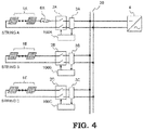
- FIG. 4 is a schematic drawing for describing a state when a series arc 6A occurs between solar panels 1A and a voltage-current sensor 3A.
- a series arc which is similar to the series arc 6A may occur on a circuit between solar panels 1B and a voltage-current sensor 3B, or between solar panels 1C and a voltage-current sensor 3C.
- circuits are symmetry, therefore a case in which the series arc 6A occurs between the solar panels 1A and the voltage-current sensor 3A will be described as an example.
- arc noise having a range from 1 kHz to 1 MHz occurs.
- Arc noise has a characteristic of 1/f, and minute noise is imposed on whole of a circuit of solar power generation system.
- noise strength when an arc does not occur, especially in a range from 1 kHz to 100 kHz, there is specific difference, therefore, as arc noise which is imposed on a current, by detecting high frequency noise in a range at least from 1 kHz to 100 kHz, occurrence of an arc can be judged.
- Propagation of arc noise is well-known. By cancelling noise from a power conditioner, occurrence of an arc can be easily detected. However, when occurrence of an arc is judged only by arc noise, in a plurality of parallel circuits, all of the arc detectors will judge such that an arc occurs.
- this patent proposes an arc judgement method in which an arc occurrence point and an arc mode can be specified not only by arc noise but also by analyzing voltage-current variation characteristic.
- FIG. 5 shows a voltage-current variation characteristic when a series arc occurs at a point shown in the schematic drawing of FIG. 4 .
- a voltage-current characteristic of solar power generation depends on solar irradiance. The larger solar irradiance is, the more maximum operation output current Ipm increases, and the smaller solar irradiance is, the smaller maximum operation output current Ipm is. Further, regardless of solar irradiance, maximum operation output voltage Vpm does not greatly variate. By control of the power conditioner 4, an operation point 11 which is maximum power is continued at all times.
- an output of maximum operation output voltage Vpm and maximum operation output current Ipm is an operation point at normal time. Further, at each string, when a string itself is normal, output voltage Voc in a case where a load is open and output current Isc in a case where a load is a short circuit are determined, in accordance with a state of a load, an operation point is on a voltage-current characteristic curve 10.
- Voltage of a voltage-current sensor 3B and 3C of a string in which a series arc does not occur decreases, current increases and an operation point is an operation point 13.
- Voltage-current of a string in which a series arc does not occur operates on the voltage-current characteristic curve 10 of a solar power generation, therefore current increases in accompany with decrease of voltage.
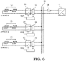
- FIG. 7 shows a voltage-current variation characteristic when a series arc occurs at a point shown in a schematic drawing of FIG. 6 .
- a series arc 6B occurs between a voltage-current sensor 3A and a power conditioner 4
- voltage of the voltage-current sensor 3A increases and current of the voltage-current sensor 3A decreases.
- an operation point is an operation point 14 after an arc occurs. This is because such that circuit impedance increases and current decreases due to occurrence of an arc.
- the operation point 14 is an operation point on the voltage-current characteristic curve 10 of normal operation.
- a voltage-current sensor 3B of a string B and a voltage-current sensor 3C of a string C voltage increases and current decreases.
- the operation point 14 of the string B and the string C after an arc occurs coincides with an operation point of the string A after an arc occurs.
- circuits are symmetry, variation amount of voltage and that of current are same.
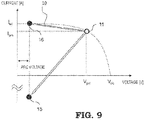
- FIG. 9 shows a voltage-current variation characteristic when a parallel arc 7A occurs at a point shown in a schematic drawing of FIG. 8 .
- Voltage of the operation point 15 is nearly arc voltage (10 V to 40 V), and current flows backward from other strings, therefore, excessive current flows backward.
- the operation point 15 is an operation point which greatly deviates from the voltage-current characteristic curve 10 of normal operation.
- voltages of a voltage-current sensors 3B and 3C of other strings decrease, and an operation point is an operation point 16 after an arc occurs.
- Voltage of the operation point 16 is nearly arc voltage (10 V to 40 V), and a value of current is same as that of short circuit current. As shown in FIG. 9 , an operation point 16 of a string in which an abnormality is not caused is on the voltage-current characteristic curve 10 of normal operation.
- FIG. 11 shows a voltage-current variation characteristic when a parallel arc 7B occurs at a point shown in a schematic drawing of FIG. 10 .
- a parallel arc 7B occurs between a voltage-current sensor 3A and a power conditioner 4
- voltage of the voltage-current sensor 3A decreases, current of the voltage-current sensor 3A increases and an operation point is an operation point 19 after an arc occurs.
- Voltage of the operation point 19 is nearly arc voltage (10 V to 40 V), and a value of current is close to that of short circuit current Isc based on the voltage-current characteristic curve 10.
- an operation point 16 is an operation point on the voltage-current characteristic curve 10 of normal operation. Operation points of other strings coincide with an operation point 19. As circuits are symmetry, variation amount of voltage and that of a current are same.
- An operation of a switch control unit 130 that is, an operation of a switch control step will be determined after an arc occurrence point is judged.
- an arc detector 100A of the string A to which a signal of a sensor which shows a variation of voltage-current of an operation point 12, after an arc shown in FIG. 5 has occurred trips a switch 2A in the vicinity of a voltage-current sensor 3A.
- an arc detector 100A to which a signal of a sensor which shows a variation of voltage-current of an operation point 15 after an arc occurs shown in FIG. 9 trips the switch 2A in the vicinity of the voltage-current sensor 3A.
- a voltage-current operation point before and after an arc occurs is analyzed, when a voltage-current operation point, after an arc occurs, deviates from a voltage-current characteristic curve of normal operation, it is judged such that an arc occurs in the own string, and the own switch 2 provided in the own string is tripped.
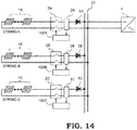
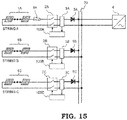
- This invention includes an application to a solar power generation system at which a backflow prevention diode 5 (5A, 5B, 5C%) as shown in FIG. 14 is provided.
- a backflow prevention diode 5 there are two cases, that is, a case in which the backflow prevention diode 5 is provided in a direction of a current which flows from solar power panels 1 to a power conditioner 4, to a cable which is provided at a positive electrode side, and a case in which the backflow prevention diode 5 is provided in a direction of a current which flows from the power conditioner 4 to a side of the solar panels 1, to a cable which is provided at a negative electrode side.
- a case in which the backflow prevention diode 5 is provided at a cable which is provided at a positive electrode side will be described as an example.
- a voltage-current variation characteristic is the same as that shown in FIG. 5 .
- a series arc 6A occurs between the solar power panels 1A and the voltage-current sensor 3A, voltage and current of the voltage-current sensor 3A decreases and an operation point is an operation point 12 after an arc occurs.
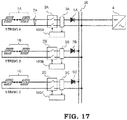
- the backflow prevention diode 5 (5A, 5B, 5C...) is provided and a series arc occurs between a DC bus to which a plurality of strings are connected and the power conditioner 4, a voltage-current variation characteristic is same as that shown in FIG. 7 .
- voltage of a voltage-current sensor 3A, 3B and 3C of each string increases and current decreases.
- an operation point is an operation point 14.
- FIG. 18 a voltage-current variation characteristic will be shown in FIG. 18 .
- a parallel arc 7A occurs between the solar power panels 1A and the voltage-current sensor 3A in a solar power generation system to which a backflow prevention diode is connected, voltage and current of the voltage-current sensor 3A decreases and an operation point is an operation point 17 after an arc occurs.
- Voltage of the operation point 17 is nearly arc voltage (10 V to 40 V), and current is not output from the solar power panels 1A and a backward flow from other strings is prevented by a backflow prevention diode. As a result, current is 0.
- voltage of the voltage-current sensor 3B and 3C of other strings decreases and current increases, and an operation point is an operation point 18 of other circuit after an arc occurs.
- Voltage of the operation point 18 is nearly arc voltage (10 V to 40 V), and current is an equal value of a short circuit current value.
- a voltage-current variation characteristic is same as that shown in FIG. 11 .
- Voltage of the voltage-current sensor 3A decreases and current increases and an operation point is an operation point 19 after an arc occurs.
- Voltage of the operation point 19 is nearly arc voltage (10 V to 40 V), and a value of current is close to a value of a short circuit current Isc based on the voltage-current characteristic curve 10.
- An operation point of the string B and the string C after an arc occurs coincides with the operation point 19 of the string A.
- an operation of a switch control unit 130 is same as that of a switch operation command in a case of FIG. 4 , FIG. 6 and FIG. 10 .
- an arc detector to which a signal of a sensor which indicates a voltage-current variation of an operation point after an arc occurs 18 is input, trips a switch 2A in the vicinity of the voltage-current sensor 3A.
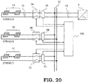
- FIG. 20 is a schematic circuit diagram showing the configuration of DC power generation system according to Embodiment 3 of this invention.
- Embodiment 1 and Embodiment 2 it is configured such that an arc detector 100 which is provided at each string judges whether to trip a switch 2 of the own string or not.
- Embodiment 3 it is configured such that data which is transmitted from a voltage-current sensor 3 (3A, 3B 7) which is provided at each string is analyzed by one arc detector 200 so as to judge an arc occurrence point and an arc mode, and output an appropriate switch operation command.
- an operation point in the voltage-current sensor 3A of the string A is an operation point 15 shown in FIG. 9 and an operation point of a voltage-current sensor 3B of a string B and an operation point of a voltage-current sensor 3C of a string C is an operation point 16 shown in FIG. 9 .
- an operation point in the voltage-current sensor 3 of each string is an operation point 19 shown in FIG. 11 .
- an operation point 16 shown in FIG. 9 and an operation point 19 shown in FIG. 11 are nearly same operation point.
- Embodiment 1 and Embodiment 2 occurrence of an arc is judged separately at each string, therefore, at a string B and a string C, it is difficult to judge whether a parallel arc occurs in the string A or a parallel arc occurs at the DC bus 20 or at a side which is closer to the power conditioner 4 than the DC bus 20.
- Embodiment 1 in a case where it is judged such that an arc occurs outside the own string, when an operation point is continued for a predetermined period of time, it is configured such that a switch is tripped so as to separate the own string.
- Embodiment 3 as shown in FIG. 20 , when signals from a voltage-current sensors 3 (3A, 3B ...) of all strings are input and judged comprehensively by an arc detector 200, an arc occurrence point can be appropriately judged. That is, as shown in FIG. 9 , in a case where an operation point in the string A is an operation point 15 and an operation point of other string is an operation point 16, it can be judged such that a parallel arc 7 occurs in the string A, and in this case, only a switch 2A is tripped.
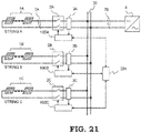
- FIG. 21 is a schematic circuit diagram showing the configuration of DC power generation system according to Embodiment 4 of this invention.
- an arc detector 100 (100A, 100B%) which is provided at each string judges whether an arc occurs in the own string or not and a result of judgement is transmitted to an arc occurrence point specifying device 201.
- Signals from all of the arc detectors 100 (100A, 100B%) are input in the arc occurrence point specifying device 201 and judged comprehensively so as to specify an arc occurrence point.
- the arc occurrence point specifying device 201 judges such that a parallel arc 7B occurs at a DC bus 20 or at a side which is closer to a power conditioner 4 than the DC bus 20, a command is transmitted to all of the arc detectors 100 so as to trip switches 2 (2A, 2B %) of all strings.
- the arc occurrence point specifying device 201 transmits a command not to trip switches other than a switch of the string A to arc detectors or switches of strings other than the string A. In a case of a series arc, similar procedure is performed.
- an arc detector which judges such that an arc occurs in the own string, immediately trips the own switch.
- an arc detector which judges such that an arc occurs outside the own string, trips the own switch when a signal from the arc occurrence specifying device 201 is received.
- Embodiment 4 in a case where an arc occurs outside a string, unlike Embodiment 1, without waiting until an abnormal operation point is continued for a predetermined period of time, an occurrence point is specified by the arc occurrence point specifying device 201, therefore more appropriate arc occurrence point can be specified.
Landscapes
- Engineering & Computer Science (AREA)
- Power Engineering (AREA)
- Photovoltaic Devices (AREA)
- Locating Faults (AREA)
Applications Claiming Priority (2)
| Application Number | Priority Date | Filing Date | Title |
|---|---|---|---|
| JP2013174105 | 2013-08-26 | ||
| PCT/JP2014/050748 WO2015029458A1 (ja) | 2013-08-26 | 2014-01-17 | 直流発電システムおよび直流発電システムの保護方法 |
Publications (3)
| Publication Number | Publication Date |
|---|---|
| EP3041104A1 EP3041104A1 (en) | 2016-07-06 |
| EP3041104A4 EP3041104A4 (en) | 2017-06-07 |
| EP3041104B1 true EP3041104B1 (en) | 2021-06-02 |
Family
ID=52586045
Family Applications (1)
| Application Number | Title | Priority Date | Filing Date |
|---|---|---|---|
| EP14840613.5A Active EP3041104B1 (en) | 2013-08-26 | 2014-01-17 | Dc power generation system and protection method for dc power generation system |
Country Status (5)
| Country | Link |
|---|---|
| US (1) | US9866017B2 (zh) |
| EP (1) | EP3041104B1 (zh) |
| JP (1) | JP6132919B2 (zh) |
| CN (1) | CN105474494B (zh) |
| WO (1) | WO2015029458A1 (zh) |
Families Citing this family (27)
| Publication number | Priority date | Publication date | Assignee | Title |
|---|---|---|---|---|
| FR2977677B1 (fr) | 2011-07-04 | 2013-08-23 | Commissariat Energie Atomique | Detection d'arcs electriques dans les installations photovoltaiques |
| EP2870669A4 (en) * | 2012-07-09 | 2016-11-09 | Solarbos Inc | INVERSE CURRENT FAULT PREVENTION IN A SOLAR PANEL |
| FR3010261B1 (fr) * | 2013-08-29 | 2015-10-02 | Commissariat Energie Atomique | Detection d'un arc electrique en parallele sur les bornes principales d'une installation photovoltaique |
| FR3010260B1 (fr) | 2013-08-29 | 2015-10-02 | Commissariat Energie Atomique | Detection d'arcs electriques dans les installations photovoltaiques |
| JP6246062B2 (ja) * | 2014-04-30 | 2017-12-13 | 三菱電機株式会社 | 直流発電システムおよび直流発電システムの保護方法 |
| FR3044489B1 (fr) * | 2015-12-01 | 2017-12-22 | Commissariat Energie Atomique | Procede et dispositif de detection d'un arc electrique parasite dans une installation photovoltaique |
| JP6597394B2 (ja) * | 2016-02-29 | 2019-10-30 | オムロン株式会社 | アーク発生位置検出装置およびアーク発生位置検出方法 |
| JP6234647B1 (ja) | 2016-06-21 | 2017-11-22 | 三菱電機株式会社 | 直流電気回路保護装置およびアーク検出方法 |
| DE112017003081T5 (de) * | 2016-06-21 | 2019-03-14 | Mitsubishi Electric Corporation | Schutzvorrichtung für eine elektrische dc-schaltung und lichtbogen-detektionsverfahren |
| JP2018028498A (ja) * | 2016-08-19 | 2018-02-22 | 富士電機機器制御株式会社 | アーク故障検出システム |
| US11538943B2 (en) | 2016-09-12 | 2022-12-27 | Phoenix Contact Gmbh & Co. Kg | Photovoltaic system, direct current hybrid switching device, use and method for switching a photovoltaic string on and off |
| LU93202B1 (de) * | 2016-09-12 | 2018-04-05 | Phoenix Contact Gmbh & Co Kg Intellectual Property Licenses & Standards | Multistrang-Photovoltaik-Anlage, Verfahren zum Betrieb einer solchen und Rückstromschutzschaltung für eine solche |
| JP6834334B2 (ja) * | 2016-10-17 | 2021-02-24 | 富士電機機器制御株式会社 | アーク故障検出システム |
| JP6834458B2 (ja) * | 2016-12-20 | 2021-02-24 | 富士電機機器制御株式会社 | アーク故障検出システム |
| US11418018B2 (en) * | 2017-02-14 | 2022-08-16 | Panasonic Intellectual Property Management Co., Ltd. | Arc detection circuit, switch system, power conditioner system and arc detection method |
| US11088528B2 (en) * | 2017-02-14 | 2021-08-10 | Panasonic Intellectual Property Management Co., Ltd. | Arc detection circuit, switch system, power conditioner system and arc detection method |
| JP2020012727A (ja) * | 2018-07-18 | 2020-01-23 | 日本電信電話株式会社 | 回線確認装置および回線確認方法 |
| CN110095702A (zh) * | 2019-05-22 | 2019-08-06 | 安徽升隆电气有限公司 | 一种电弧性能分析仪器 |
| JP7370666B2 (ja) * | 2019-11-01 | 2023-10-30 | 日東工業株式会社 | 放電検出システム |
| CN110618366A (zh) * | 2019-11-05 | 2019-12-27 | 阳光电源股份有限公司 | 一种直流电弧检测方法及装置 |
| KR102341332B1 (ko) * | 2019-12-03 | 2021-12-21 | 한국에너지기술연구원 | 에너지원의 출력경로에서 아크를 검출하는 장치 |
| CN111817586B (zh) * | 2020-07-07 | 2021-05-04 | 武汉理工大学 | 一种矿井直流架线用整流电源装置及其架线短路检测方法 |
| CN111983402A (zh) * | 2020-08-20 | 2020-11-24 | 阳光电源股份有限公司 | 一种直流电弧故障检测方法及光伏逆变系统 |
| CA3192723A1 (en) * | 2020-09-25 | 2022-03-31 | Patrick L. Chapman | High-power microinverter and system |
| CN112468086B (zh) * | 2020-11-13 | 2022-01-25 | 丰郅(上海)新能源科技有限公司 | 应用于光伏能源的电弧监测系统及电弧监测方法 |
| CN112462176B (zh) * | 2020-11-13 | 2022-06-28 | 丰郅(上海)新能源科技有限公司 | 支持检测光伏系统直流电弧故障的装置及方法 |
| CN113782400A (zh) * | 2021-09-10 | 2021-12-10 | 柳州铁道职业技术学院 | 一种新能源汽车动力电池直流高压防逆电反流保险管 |
Family Cites Families (19)
| Publication number | Priority date | Publication date | Assignee | Title |
|---|---|---|---|---|
| CN1529929A (zh) | 2000-11-13 | 2004-09-15 | 伊顿公司 | 直流电力系统中飞弧的检测 |
| US20040027749A1 (en) | 2001-11-09 | 2004-02-12 | Zuercher Joseph C. | Detection of arcing in dc electrical systems |
| US6984987B2 (en) * | 2003-06-12 | 2006-01-10 | Sharper Image Corporation | Electro-kinetic air transporter and conditioner devices with enhanced arching detection and suppression features |
| CN1696723A (zh) * | 2004-05-14 | 2005-11-16 | 人间电气技术株式会社 | 电弧故障检测设备 |
| US20070279068A1 (en) * | 2006-05-31 | 2007-12-06 | Harres Daniel N | Power diagnostic system and method |
| US7368918B2 (en) * | 2006-07-27 | 2008-05-06 | Siemens Energy & Automation | Devices, systems, and methods for adaptive RF sensing in arc fault detection |
| CN101308108B (zh) * | 2007-05-15 | 2011-06-29 | 清华大学 | 一种包含一维纳米材料敏感元件的传感器的制备方法 |
| US8179145B2 (en) * | 2008-01-24 | 2012-05-15 | Siemens Industry, Inc. | Method and apparatus for testing AFCI device for series arc detection |
| JP5419579B2 (ja) * | 2009-05-28 | 2014-02-19 | 京セラ株式会社 | アーク検出手段とそれを用いた制御手段及び連絡手段 |
| EP2741388B1 (en) * | 2009-07-23 | 2015-10-21 | Enphase Energy, Inc. | Method and apparatus for detection and control of DC arc faults |
| AT509251A1 (de) | 2009-08-14 | 2011-07-15 | Fronius Int Gmbh | 4erfahren zur lichtbogendetektion in photovoltaikanlagen und eine solche photovoltaikanlage |
| US20110090607A1 (en) | 2009-10-20 | 2011-04-21 | Luebke Charles J | String and system employing direct current electrical generating modules and a number of string protectors |
| US8218274B2 (en) * | 2009-12-15 | 2012-07-10 | Eaton Corporation | Direct current arc fault circuit interrupter, direct current arc fault detector, noise blanking circuit for a direct current arc fault circuit interrupter, and method of detecting arc faults |
| KR20120032925A (ko) * | 2010-09-29 | 2012-04-06 | 삼성전자주식회사 | 전기기기, 전기기기 시스템 및 그 아크 결함 검출 방법 |
| GB2485527B (en) | 2010-11-09 | 2012-12-19 | Solaredge Technologies Ltd | Arc detection and prevention in a power generation system |
| CN102288857B (zh) * | 2011-05-18 | 2013-06-19 | 浙江科技学院 | 一种故障电弧的辨识检测方法及其检测保护装置 |
| JP5888972B2 (ja) * | 2011-12-22 | 2016-03-22 | 三菱電機株式会社 | 太陽光発電システム |
| DE102012104314B4 (de) * | 2012-05-18 | 2014-04-10 | Sma Solar Technology Ag | Verfahren und Vorrichtung zum Lokalisieren und Löschen eines Lichtbogens |
| US9768605B2 (en) * | 2014-12-29 | 2017-09-19 | Eaton Corporation | Arc fault detection system and method and circuit interrupter employing same |
-
2014
- 2014-01-17 US US14/911,238 patent/US9866017B2/en active Active
- 2014-01-17 JP JP2015534010A patent/JP6132919B2/ja active Active
- 2014-01-17 CN CN201480046617.5A patent/CN105474494B/zh active Active
- 2014-01-17 WO PCT/JP2014/050748 patent/WO2015029458A1/ja active Application Filing
- 2014-01-17 EP EP14840613.5A patent/EP3041104B1/en active Active
Non-Patent Citations (1)
| Title |
|---|
| None * |
Also Published As
| Publication number | Publication date |
|---|---|
| US9866017B2 (en) | 2018-01-09 |
| EP3041104A1 (en) | 2016-07-06 |
| WO2015029458A1 (ja) | 2015-03-05 |
| EP3041104A4 (en) | 2017-06-07 |
| JP6132919B2 (ja) | 2017-05-24 |
| US20160181799A1 (en) | 2016-06-23 |
| JPWO2015029458A1 (ja) | 2017-03-02 |
| CN105474494B (zh) | 2017-10-03 |
| CN105474494A (zh) | 2016-04-06 |
Similar Documents
| Publication | Publication Date | Title |
|---|---|---|
| EP3041104B1 (en) | Dc power generation system and protection method for dc power generation system | |
| JP6246062B2 (ja) | 直流発電システムおよび直流発電システムの保護方法 | |
| US9853443B2 (en) | ARC fault detection and extinguishing | |
| US9995796B1 (en) | Identifying an arc-fault type in photovoltaic arrays | |
| US8837097B2 (en) | Protection, monitoring or indication apparatus for a direct current electrical generating apparatus or a plurality of strings | |
| EP2681821B1 (en) | Method and system for detecting an arc fault in a power circuit | |
| US9148086B2 (en) | Photovoltaic DC sub-array control system and method | |
| JP5888972B2 (ja) | 太陽光発電システム | |
| AU2014224084B2 (en) | Electrical control and protection device | |
| US20170317500A1 (en) | System and method of sensing and isolating a ground fault in a dc-to-ac power conversion system | |
| CN109417285B (zh) | 直流电气回路保护装置及电弧检测方法 | |
| EP2580828A1 (en) | Fault protection of hvdc transmission lines | |
| US9391441B2 (en) | Zone selective interlocking for optical flash detection suppression | |
| EP3024104B1 (en) | Capture of power quality information at the time a device fails | |
| KR101881411B1 (ko) | 태양광 발전 및 태양광발전 에너지 저장 시스템, 그리고 태양광 발전 및 태양광발전 에너지 저장 시스템에서의 아크 검출 및 차단방법 | |
| US20190044323A1 (en) | Devices and methods for de-energizing a photovoltaic system | |
| US6867958B2 (en) | Loop restoration scheme for distribution feeders | |
| JP2018028498A (ja) | アーク故障検出システム | |
| KR20150128124A (ko) | 과전류 계전기 | |
| JP6597394B2 (ja) | アーク発生位置検出装置およびアーク発生位置検出方法 | |
| EP3391489B1 (en) | Ground fault detection and interrupt system | |
| KR102263463B1 (ko) | 아크 검출기를 포함하는 태양광 발전장치 | |
| KR102175998B1 (ko) | 전력용 반도체형 한류기를 이용한 멀티 터미널 직류 배전계통의 보호 방법, 장치 및 시스템 | |
| KR102670331B1 (ko) | Dc 개폐 기능을 가진 태양광 접속반 | |
| KR102423868B1 (ko) | 스마트 수배전반 |
Legal Events
| Date | Code | Title | Description |
|---|---|---|---|
| PUAI | Public reference made under article 153(3) epc to a published international application that has entered the european phase |
Free format text: ORIGINAL CODE: 0009012 |
|
| 17P | Request for examination filed |
Effective date: 20160210 |
|
| AK | Designated contracting states |
Kind code of ref document: A1 Designated state(s): AL AT BE BG CH CY CZ DE DK EE ES FI FR GB GR HR HU IE IS IT LI LT LU LV MC MK MT NL NO PL PT RO RS SE SI SK SM TR |
|
| AX | Request for extension of the european patent |
Extension state: BA ME |
|
| DAX | Request for extension of the european patent (deleted) | ||
| RIN1 | Information on inventor provided before grant (corrected) |
Inventor name: YANO, TOMOTAKA Inventor name: KANEMARU, MAKOTO Inventor name: SHINDOI, TAKESHI |
|
| A4 | Supplementary search report drawn up and despatched |
Effective date: 20170508 |
|
| RIC1 | Information provided on ipc code assigned before grant |
Ipc: G01R 31/08 20060101ALI20170428BHEP Ipc: H02H 3/16 20060101ALI20170428BHEP Ipc: G01R 31/02 20060101ALI20170428BHEP Ipc: H02H 3/44 20060101ALI20170428BHEP Ipc: H02H 7/26 20060101AFI20170428BHEP Ipc: H02H 3/50 20060101ALI20170428BHEP |
|
| GRAP | Despatch of communication of intention to grant a patent |
Free format text: ORIGINAL CODE: EPIDOSNIGR1 |
|
| RIC1 | Information provided on ipc code assigned before grant |
Ipc: H02H 3/44 20060101ALI20200409BHEP Ipc: H02H 3/50 20060101ALI20200409BHEP Ipc: G01R 31/08 20200101ALI20200409BHEP Ipc: H02H 7/26 20060101AFI20200409BHEP Ipc: H02H 3/16 20060101ALI20200409BHEP |
|
| STAA | Information on the status of an ep patent application or granted ep patent |
Free format text: STATUS: GRANT OF PATENT IS INTENDED |
|
| INTG | Intention to grant announced |
Effective date: 20200514 |
|
| GRAJ | Information related to disapproval of communication of intention to grant by the applicant or resumption of examination proceedings by the epo deleted |
Free format text: ORIGINAL CODE: EPIDOSDIGR1 |
|
| STAA | Information on the status of an ep patent application or granted ep patent |
Free format text: STATUS: REQUEST FOR EXAMINATION WAS MADE |
|
| INTC | Intention to grant announced (deleted) | ||
| GRAP | Despatch of communication of intention to grant a patent |
Free format text: ORIGINAL CODE: EPIDOSNIGR1 |
|
| STAA | Information on the status of an ep patent application or granted ep patent |
Free format text: STATUS: GRANT OF PATENT IS INTENDED |
|
| INTG | Intention to grant announced |
Effective date: 20201217 |
|
| GRAS | Grant fee paid |
Free format text: ORIGINAL CODE: EPIDOSNIGR3 |
|
| GRAA | (expected) grant |
Free format text: ORIGINAL CODE: 0009210 |
|
| STAA | Information on the status of an ep patent application or granted ep patent |
Free format text: STATUS: THE PATENT HAS BEEN GRANTED |
|
| REG | Reference to a national code |
Ref country code: CH Ref legal event code: EP |
|
| AK | Designated contracting states |
Kind code of ref document: B1 Designated state(s): AL AT BE BG CH CY CZ DE DK EE ES FI FR GB GR HR HU IE IS IT LI LT LU LV MC MK MT NL NO PL PT RO RS SE SI SK SM TR |
|
| REG | Reference to a national code |
Ref country code: GB Ref legal event code: FG4D |
|
| REG | Reference to a national code |
Ref country code: AT Ref legal event code: REF Ref document number: 1399332 Country of ref document: AT Kind code of ref document: T Effective date: 20210615 |
|
| REG | Reference to a national code |
Ref country code: IE Ref legal event code: FG4D |
|
| REG | Reference to a national code |
Ref country code: DE Ref legal event code: R096 Ref document number: 602014077938 Country of ref document: DE |
|
| REG | Reference to a national code |
Ref country code: LT Ref legal event code: MG9D |
|
| PG25 | Lapsed in a contracting state [announced via postgrant information from national office to epo] |
Ref country code: FI Free format text: LAPSE BECAUSE OF FAILURE TO SUBMIT A TRANSLATION OF THE DESCRIPTION OR TO PAY THE FEE WITHIN THE PRESCRIBED TIME-LIMIT Effective date: 20210602 Ref country code: LT Free format text: LAPSE BECAUSE OF FAILURE TO SUBMIT A TRANSLATION OF THE DESCRIPTION OR TO PAY THE FEE WITHIN THE PRESCRIBED TIME-LIMIT Effective date: 20210602 Ref country code: BG Free format text: LAPSE BECAUSE OF FAILURE TO SUBMIT A TRANSLATION OF THE DESCRIPTION OR TO PAY THE FEE WITHIN THE PRESCRIBED TIME-LIMIT Effective date: 20210902 Ref country code: HR Free format text: LAPSE BECAUSE OF FAILURE TO SUBMIT A TRANSLATION OF THE DESCRIPTION OR TO PAY THE FEE WITHIN THE PRESCRIBED TIME-LIMIT Effective date: 20210602 |
|
| REG | Reference to a national code |
Ref country code: NL Ref legal event code: MP Effective date: 20210602 |
|
| REG | Reference to a national code |
Ref country code: AT Ref legal event code: MK05 Ref document number: 1399332 Country of ref document: AT Kind code of ref document: T Effective date: 20210602 |
|
| PG25 | Lapsed in a contracting state [announced via postgrant information from national office to epo] |
Ref country code: GR Free format text: LAPSE BECAUSE OF FAILURE TO SUBMIT A TRANSLATION OF THE DESCRIPTION OR TO PAY THE FEE WITHIN THE PRESCRIBED TIME-LIMIT Effective date: 20210903 Ref country code: LV Free format text: LAPSE BECAUSE OF FAILURE TO SUBMIT A TRANSLATION OF THE DESCRIPTION OR TO PAY THE FEE WITHIN THE PRESCRIBED TIME-LIMIT Effective date: 20210602 Ref country code: PL Free format text: LAPSE BECAUSE OF FAILURE TO SUBMIT A TRANSLATION OF THE DESCRIPTION OR TO PAY THE FEE WITHIN THE PRESCRIBED TIME-LIMIT Effective date: 20210602 Ref country code: NO Free format text: LAPSE BECAUSE OF FAILURE TO SUBMIT A TRANSLATION OF THE DESCRIPTION OR TO PAY THE FEE WITHIN THE PRESCRIBED TIME-LIMIT Effective date: 20210902 Ref country code: RS Free format text: LAPSE BECAUSE OF FAILURE TO SUBMIT A TRANSLATION OF THE DESCRIPTION OR TO PAY THE FEE WITHIN THE PRESCRIBED TIME-LIMIT Effective date: 20210602 Ref country code: SE Free format text: LAPSE BECAUSE OF FAILURE TO SUBMIT A TRANSLATION OF THE DESCRIPTION OR TO PAY THE FEE WITHIN THE PRESCRIBED TIME-LIMIT Effective date: 20210602 |
|
| PG25 | Lapsed in a contracting state [announced via postgrant information from national office to epo] |
Ref country code: EE Free format text: LAPSE BECAUSE OF FAILURE TO SUBMIT A TRANSLATION OF THE DESCRIPTION OR TO PAY THE FEE WITHIN THE PRESCRIBED TIME-LIMIT Effective date: 20210602 Ref country code: CZ Free format text: LAPSE BECAUSE OF FAILURE TO SUBMIT A TRANSLATION OF THE DESCRIPTION OR TO PAY THE FEE WITHIN THE PRESCRIBED TIME-LIMIT Effective date: 20210602 Ref country code: SK Free format text: LAPSE BECAUSE OF FAILURE TO SUBMIT A TRANSLATION OF THE DESCRIPTION OR TO PAY THE FEE WITHIN THE PRESCRIBED TIME-LIMIT Effective date: 20210602 Ref country code: SM Free format text: LAPSE BECAUSE OF FAILURE TO SUBMIT A TRANSLATION OF THE DESCRIPTION OR TO PAY THE FEE WITHIN THE PRESCRIBED TIME-LIMIT Effective date: 20210602 Ref country code: AT Free format text: LAPSE BECAUSE OF FAILURE TO SUBMIT A TRANSLATION OF THE DESCRIPTION OR TO PAY THE FEE WITHIN THE PRESCRIBED TIME-LIMIT Effective date: 20210602 Ref country code: RO Free format text: LAPSE BECAUSE OF FAILURE TO SUBMIT A TRANSLATION OF THE DESCRIPTION OR TO PAY THE FEE WITHIN THE PRESCRIBED TIME-LIMIT Effective date: 20210602 Ref country code: NL Free format text: LAPSE BECAUSE OF FAILURE TO SUBMIT A TRANSLATION OF THE DESCRIPTION OR TO PAY THE FEE WITHIN THE PRESCRIBED TIME-LIMIT Effective date: 20210602 Ref country code: PT Free format text: LAPSE BECAUSE OF FAILURE TO SUBMIT A TRANSLATION OF THE DESCRIPTION OR TO PAY THE FEE WITHIN THE PRESCRIBED TIME-LIMIT Effective date: 20211004 Ref country code: ES Free format text: LAPSE BECAUSE OF FAILURE TO SUBMIT A TRANSLATION OF THE DESCRIPTION OR TO PAY THE FEE WITHIN THE PRESCRIBED TIME-LIMIT Effective date: 20210602 |
|
| REG | Reference to a national code |
Ref country code: DE Ref legal event code: R097 Ref document number: 602014077938 Country of ref document: DE |
|
| PLBE | No opposition filed within time limit |
Free format text: ORIGINAL CODE: 0009261 |
|
| STAA | Information on the status of an ep patent application or granted ep patent |
Free format text: STATUS: NO OPPOSITION FILED WITHIN TIME LIMIT |
|
| PG25 | Lapsed in a contracting state [announced via postgrant information from national office to epo] |
Ref country code: DK Free format text: LAPSE BECAUSE OF FAILURE TO SUBMIT A TRANSLATION OF THE DESCRIPTION OR TO PAY THE FEE WITHIN THE PRESCRIBED TIME-LIMIT Effective date: 20210602 |
|
| 26N | No opposition filed |
Effective date: 20220303 |
|
| PG25 | Lapsed in a contracting state [announced via postgrant information from national office to epo] |
Ref country code: AL Free format text: LAPSE BECAUSE OF FAILURE TO SUBMIT A TRANSLATION OF THE DESCRIPTION OR TO PAY THE FEE WITHIN THE PRESCRIBED TIME-LIMIT Effective date: 20210602 |
|
| PG25 | Lapsed in a contracting state [announced via postgrant information from national office to epo] |
Ref country code: IT Free format text: LAPSE BECAUSE OF FAILURE TO SUBMIT A TRANSLATION OF THE DESCRIPTION OR TO PAY THE FEE WITHIN THE PRESCRIBED TIME-LIMIT Effective date: 20210602 |
|
| PG25 | Lapsed in a contracting state [announced via postgrant information from national office to epo] |
Ref country code: MC Free format text: LAPSE BECAUSE OF FAILURE TO SUBMIT A TRANSLATION OF THE DESCRIPTION OR TO PAY THE FEE WITHIN THE PRESCRIBED TIME-LIMIT Effective date: 20210602 |
|
| REG | Reference to a national code |
Ref country code: CH Ref legal event code: PL |
|
| REG | Reference to a national code |
Ref country code: BE Ref legal event code: MM Effective date: 20220131 |
|
| PG25 | Lapsed in a contracting state [announced via postgrant information from national office to epo] |
Ref country code: LU Free format text: LAPSE BECAUSE OF NON-PAYMENT OF DUE FEES Effective date: 20220117 |
|
| PG25 | Lapsed in a contracting state [announced via postgrant information from national office to epo] |
Ref country code: FR Free format text: LAPSE BECAUSE OF NON-PAYMENT OF DUE FEES Effective date: 20220131 Ref country code: BE Free format text: LAPSE BECAUSE OF NON-PAYMENT OF DUE FEES Effective date: 20220131 |
|
| PG25 | Lapsed in a contracting state [announced via postgrant information from national office to epo] |
Ref country code: LI Free format text: LAPSE BECAUSE OF NON-PAYMENT OF DUE FEES Effective date: 20220131 Ref country code: CH Free format text: LAPSE BECAUSE OF NON-PAYMENT OF DUE FEES Effective date: 20220131 |
|
| PG25 | Lapsed in a contracting state [announced via postgrant information from national office to epo] |
Ref country code: IE Free format text: LAPSE BECAUSE OF NON-PAYMENT OF DUE FEES Effective date: 20220117 |
|
| P01 | Opt-out of the competence of the unified patent court (upc) registered |
Effective date: 20230512 |
|
| PGFP | Annual fee paid to national office [announced via postgrant information from national office to epo] |
Ref country code: GB Payment date: 20231130 Year of fee payment: 11 |
|
| REG | Reference to a national code |
Ref country code: DE Ref legal event code: R084 Ref document number: 602014077938 Country of ref document: DE |
|
| PG25 | Lapsed in a contracting state [announced via postgrant information from national office to epo] |
Ref country code: HU Free format text: LAPSE BECAUSE OF FAILURE TO SUBMIT A TRANSLATION OF THE DESCRIPTION OR TO PAY THE FEE WITHIN THE PRESCRIBED TIME-LIMIT; INVALID AB INITIO Effective date: 20140117 |
|
| PG25 | Lapsed in a contracting state [announced via postgrant information from national office to epo] |
Ref country code: MK Free format text: LAPSE BECAUSE OF FAILURE TO SUBMIT A TRANSLATION OF THE DESCRIPTION OR TO PAY THE FEE WITHIN THE PRESCRIBED TIME-LIMIT Effective date: 20210602 Ref country code: CY Free format text: LAPSE BECAUSE OF FAILURE TO SUBMIT A TRANSLATION OF THE DESCRIPTION OR TO PAY THE FEE WITHIN THE PRESCRIBED TIME-LIMIT Effective date: 20210602 |
|
| PGFP | Annual fee paid to national office [announced via postgrant information from national office to epo] |
Ref country code: DE Payment date: 20231128 Year of fee payment: 11 |
|
| PG25 | Lapsed in a contracting state [announced via postgrant information from national office to epo] |
Ref country code: MT Free format text: LAPSE BECAUSE OF FAILURE TO SUBMIT A TRANSLATION OF THE DESCRIPTION OR TO PAY THE FEE WITHIN THE PRESCRIBED TIME-LIMIT Effective date: 20210602 |