EP3041001A1 - Debris filtration apparatus - Google Patents
Debris filtration apparatus Download PDFInfo
- Publication number
- EP3041001A1 EP3041001A1 EP15200691.2A EP15200691A EP3041001A1 EP 3041001 A1 EP3041001 A1 EP 3041001A1 EP 15200691 A EP15200691 A EP 15200691A EP 3041001 A1 EP3041001 A1 EP 3041001A1
- Authority
- EP
- European Patent Office
- Prior art keywords
- unit
- debris
- filtration apparatus
- cooling water
- screens
- Prior art date
- Legal status (The legal status is an assumption and is not a legal conclusion. Google has not performed a legal analysis and makes no representation as to the accuracy of the status listed.)
- Granted
Links
Images




Classifications
-
- F—MECHANICAL ENGINEERING; LIGHTING; HEATING; WEAPONS; BLASTING
- F28—HEAT EXCHANGE IN GENERAL
- F28F—DETAILS OF HEAT-EXCHANGE AND HEAT-TRANSFER APPARATUS, OF GENERAL APPLICATION
- F28F19/00—Preventing the formation of deposits or corrosion, e.g. by using filters or scrapers
- F28F19/01—Preventing the formation of deposits or corrosion, e.g. by using filters or scrapers by using means for separating solid materials from heat-exchange fluids, e.g. filters
-
- B—PERFORMING OPERATIONS; TRANSPORTING
- B01—PHYSICAL OR CHEMICAL PROCESSES OR APPARATUS IN GENERAL
- B01D—SEPARATION
- B01D29/00—Filters with filtering elements stationary during filtration, e.g. pressure or suction filters, not covered by groups B01D24/00 - B01D27/00; Filtering elements therefor
- B01D29/11—Filters with filtering elements stationary during filtration, e.g. pressure or suction filters, not covered by groups B01D24/00 - B01D27/00; Filtering elements therefor with bag, cage, hose, tube, sleeve or like filtering elements
-
- B—PERFORMING OPERATIONS; TRANSPORTING
- B01—PHYSICAL OR CHEMICAL PROCESSES OR APPARATUS IN GENERAL
- B01D—SEPARATION
- B01D29/00—Filters with filtering elements stationary during filtration, e.g. pressure or suction filters, not covered by groups B01D24/00 - B01D27/00; Filtering elements therefor
- B01D29/50—Filters with filtering elements stationary during filtration, e.g. pressure or suction filters, not covered by groups B01D24/00 - B01D27/00; Filtering elements therefor with multiple filtering elements, characterised by their mutual disposition
- B01D29/52—Filters with filtering elements stationary during filtration, e.g. pressure or suction filters, not covered by groups B01D24/00 - B01D27/00; Filtering elements therefor with multiple filtering elements, characterised by their mutual disposition in parallel connection
-
- B—PERFORMING OPERATIONS; TRANSPORTING
- B01—PHYSICAL OR CHEMICAL PROCESSES OR APPARATUS IN GENERAL
- B01D—SEPARATION
- B01D29/00—Filters with filtering elements stationary during filtration, e.g. pressure or suction filters, not covered by groups B01D24/00 - B01D27/00; Filtering elements therefor
- B01D29/60—Filters with filtering elements stationary during filtration, e.g. pressure or suction filters, not covered by groups B01D24/00 - B01D27/00; Filtering elements therefor integrally combined with devices for controlling the filtration
- B01D29/606—Filters with filtering elements stationary during filtration, e.g. pressure or suction filters, not covered by groups B01D24/00 - B01D27/00; Filtering elements therefor integrally combined with devices for controlling the filtration by pressure measuring
-
- B—PERFORMING OPERATIONS; TRANSPORTING
- B01—PHYSICAL OR CHEMICAL PROCESSES OR APPARATUS IN GENERAL
- B01D—SEPARATION
- B01D29/00—Filters with filtering elements stationary during filtration, e.g. pressure or suction filters, not covered by groups B01D24/00 - B01D27/00; Filtering elements therefor
- B01D29/96—Filters with filtering elements stationary during filtration, e.g. pressure or suction filters, not covered by groups B01D24/00 - B01D27/00; Filtering elements therefor in which the filtering elements are moved between filtering operations; Particular measures for removing or replacing the filtering elements; Transport systems for filters
-
- B—PERFORMING OPERATIONS; TRANSPORTING
- B01—PHYSICAL OR CHEMICAL PROCESSES OR APPARATUS IN GENERAL
- B01D—SEPARATION
- B01D33/00—Filters with filtering elements which move during the filtering operation
-
- B—PERFORMING OPERATIONS; TRANSPORTING
- B01—PHYSICAL OR CHEMICAL PROCESSES OR APPARATUS IN GENERAL
- B01D—SEPARATION
- B01D33/00—Filters with filtering elements which move during the filtering operation
- B01D33/15—Filters with filtering elements which move during the filtering operation with rotary plane filtering surfaces
-
- B—PERFORMING OPERATIONS; TRANSPORTING
- B01—PHYSICAL OR CHEMICAL PROCESSES OR APPARATUS IN GENERAL
- B01D—SEPARATION
- B01D33/00—Filters with filtering elements which move during the filtering operation
- B01D33/15—Filters with filtering elements which move during the filtering operation with rotary plane filtering surfaces
- B01D33/17—Filters with filtering elements which move during the filtering operation with rotary plane filtering surfaces with rotary filtering tables
- B01D33/19—Filters with filtering elements which move during the filtering operation with rotary plane filtering surfaces with rotary filtering tables the table surface being divided in successively tilted sectors or cells, e.g. for discharging the filter cake
-
- B—PERFORMING OPERATIONS; TRANSPORTING
- B01—PHYSICAL OR CHEMICAL PROCESSES OR APPARATUS IN GENERAL
- B01D—SEPARATION
- B01D35/00—Filtering devices having features not specifically covered by groups B01D24/00 - B01D33/00, or for applications not specifically covered by groups B01D24/00 - B01D33/00; Auxiliary devices for filtration; Filter housing constructions
-
- B—PERFORMING OPERATIONS; TRANSPORTING
- B01—PHYSICAL OR CHEMICAL PROCESSES OR APPARATUS IN GENERAL
- B01D—SEPARATION
- B01D35/00—Filtering devices having features not specifically covered by groups B01D24/00 - B01D33/00, or for applications not specifically covered by groups B01D24/00 - B01D33/00; Auxiliary devices for filtration; Filter housing constructions
- B01D35/02—Filters adapted for location in special places, e.g. pipe-lines, pumps, stop-cocks
-
- B—PERFORMING OPERATIONS; TRANSPORTING
- B01—PHYSICAL OR CHEMICAL PROCESSES OR APPARATUS IN GENERAL
- B01D—SEPARATION
- B01D35/00—Filtering devices having features not specifically covered by groups B01D24/00 - B01D33/00, or for applications not specifically covered by groups B01D24/00 - B01D33/00; Auxiliary devices for filtration; Filter housing constructions
- B01D35/14—Safety devices specially adapted for filtration; Devices for indicating clogging
- B01D35/147—Bypass or safety valves
-
- F—MECHANICAL ENGINEERING; LIGHTING; HEATING; WEAPONS; BLASTING
- F22—STEAM GENERATION
- F22B—METHODS OF STEAM GENERATION; STEAM BOILERS
- F22B37/00—Component parts or details of steam boilers
- F22B37/02—Component parts or details of steam boilers applicable to more than one kind or type of steam boiler
- F22B37/48—Devices or arrangements for removing water, minerals or sludge from boilers ; Arrangement of cleaning apparatus in boilers; Combinations thereof with boilers
-
- G—PHYSICS
- G21—NUCLEAR PHYSICS; NUCLEAR ENGINEERING
- G21C—NUCLEAR REACTORS
- G21C19/00—Arrangements for treating, for handling, or for facilitating the handling of, fuel or other materials which are used within the reactor, e.g. within its pressure vessel
- G21C19/28—Arrangements for introducing fluent material into the reactor core; Arrangements for removing fluent material from the reactor core
- G21C19/30—Arrangements for introducing fluent material into the reactor core; Arrangements for removing fluent material from the reactor core with continuous purification of circulating fluent material, e.g. by extraction of fission products deterioration or corrosion products, impurities, e.g. by cold traps
- G21C19/307—Arrangements for introducing fluent material into the reactor core; Arrangements for removing fluent material from the reactor core with continuous purification of circulating fluent material, e.g. by extraction of fission products deterioration or corrosion products, impurities, e.g. by cold traps specially adapted for liquids
-
- G—PHYSICS
- G21—NUCLEAR PHYSICS; NUCLEAR ENGINEERING
- G21D—NUCLEAR POWER PLANT
- G21D1/00—Details of nuclear power plant
- G21D1/006—Details of nuclear power plant primary side of steam generators
-
- Y—GENERAL TAGGING OF NEW TECHNOLOGICAL DEVELOPMENTS; GENERAL TAGGING OF CROSS-SECTIONAL TECHNOLOGIES SPANNING OVER SEVERAL SECTIONS OF THE IPC; TECHNICAL SUBJECTS COVERED BY FORMER USPC CROSS-REFERENCE ART COLLECTIONS [XRACs] AND DIGESTS
- Y02—TECHNOLOGIES OR APPLICATIONS FOR MITIGATION OR ADAPTATION AGAINST CLIMATE CHANGE
- Y02E—REDUCTION OF GREENHOUSE GAS [GHG] EMISSIONS, RELATED TO ENERGY GENERATION, TRANSMISSION OR DISTRIBUTION
- Y02E30/00—Energy generation of nuclear origin
-
- Y—GENERAL TAGGING OF NEW TECHNOLOGICAL DEVELOPMENTS; GENERAL TAGGING OF CROSS-SECTIONAL TECHNOLOGIES SPANNING OVER SEVERAL SECTIONS OF THE IPC; TECHNICAL SUBJECTS COVERED BY FORMER USPC CROSS-REFERENCE ART COLLECTIONS [XRACs] AND DIGESTS
- Y02—TECHNOLOGIES OR APPLICATIONS FOR MITIGATION OR ADAPTATION AGAINST CLIMATE CHANGE
- Y02E—REDUCTION OF GREENHOUSE GAS [GHG] EMISSIONS, RELATED TO ENERGY GENERATION, TRANSMISSION OR DISTRIBUTION
- Y02E30/00—Energy generation of nuclear origin
- Y02E30/30—Nuclear fission reactors
Definitions
- Exemplary embodiments of the present disclosure relates to a debris filtration apparatus which filters out debris from cooling water to be supplied to a target structure, which is required to be cooled by the cooling water, whereby the target structure can be reliably cooled, and which is configured such that debris deposited on a screen unit can be reliably removed, and even when a large amount of debris is deposited on the screen unit, cooling water can be supplied to the target structure so as to ensure stable cooling operation.
- thermoelectric power plants or nuclear power plants are equipped with apparatuses such as a heat exchanger and a condenser.
- apparatuses such as a heat exchanger and a condenser.
- a pipe unit having a hollow structure is coupled to the heat exchanger or condenser.
- Cooling water is supplied to the heat exchanger or condenser through the pipe unit. Because various kinds of debris may be deposited in the pipe unit and debris may be contained in cooling water, a separate debris removal unit (not shown) is used to remove such debris from cooling water such that only cooling water can be supplied to the heat exchanger or condenser to which the pipe unit is coupled.
- a debris filtration apparatus has been used to filter out debris from cooling water before the cooling water is supplied to a heat exchanger or condenser.
- the debris filtration apparatus may be disabled or cooling water may not be supplied to the heat exchanger or condenser.
- thermoelectric power plant For example, if cooling water cannot be supplied to a condenser installed in a thermo-electric power plant, the operation of the thermoelectric power plant may be partially disabled or the operation of peripheral apparatuses connected to the condenser may be interrupted, thus making power generation impossible. Given this, it is very important to stably and reliably supply cooling water to the condenser.
- An object of the present disclosure is to provide a debris filtration apparatus which makes it possible to reliably supply cooling water to a heat exchange target structure equipped in various kinds of power plants.
- Another object of the present disclosure is to provide a debris filtration apparatus which is configured such that when bypass operation is required because of a large amount of debris deposited in the debris filtration apparatus, the bypass operation can be easily embodied, thus promoting the stable operation of the target structure and a power plant equipped with the target structure.
- a debris filtration apparatus for removing debris from cooling water, comprising: a support unit including first to n-th unit supports arranged, to form a radial form, in a circumferential direction around a support housing disposed on an upper portion of a rotor unit, the rotor unit being configured to rotate at a predetermined speed in a chamber housing; a screen unit including first to n-th unit screens disposed between the first to n-th unit supports and configured to filter out debris from the cooling water; and a bypass unit configured, when a load applied to the screen unit is increased to a predetermined level by deposition of debris on the screen unit, to selectively rotate each of the first to n-th unit screens relative to the support unit and allow flow of the cooling water.
- the bypass unit may be configured such that: a first end of each of the first to n-th unit screens is rotatably coupled to the support housing by a hinge, and a second end thereof is connected to the chamber housing by a connector; and when a load is increased to the predetermined level by deposition of debris on the screen unit, the connector is broken.
- the connector may extend from an outside of the chamber housing toward the corresponding one of the first to n-th unit screens.
- the connector may include a reduced-diameter part formed such that a diameter thereof is reduced from opposite ends thereof to a medial portion with respect to a longitudinal direction of the connector.
- the first to n-th unit screens may be oriented in a horizontal direction between the first to n-th unit supports, and each of the first to n-th unit screens may be configured such that an outer end thereof that faces the chamber housing is rotatable around the corresponding hinge toward the support housing.
- the bypass unit may include: first to n-th unit cylinders disposed outside the chamber housing toward the respective first to n-th unit screens; and first to n-th unit pistons configured to move forward from the respective first to n-th unit cylinders toward corresponding insert holes formed in the first to n-th unit screens or move backward away from the insert holes.
- the bypass unit may include: a rotating shaft connected at one end thereof to a frame provided on the first to n-th unit screens; and a motor unit configured to selectively rotate the rotating shaft.
- the motor unit may be configured to rotate the rotating shaft connected to at least one or multiple ones of the first to n-th unit screens.
- the debris filtration apparatus in accordance with another aspect of the present disclosure may further include a differential pressure sensor installed in the chamber housing and configured to measure a pressure of the cooling water that passes through the screen unit.
- the differential pressure sensor may include: a first sensor disposed below the screen unit and configured to measure a pressure of the cooling water that is in a state before passing through the screen unit; and a second sensor disposed over the screen unit and configured to measure a pressure of the cooling water that has passed through the screen unit.
- the differential pressure sensor may include a plurality of differential pressure sensors disposed in the chamber housing at positions spaced apart from each other at regular intervals in a circumferential direction.
- the bypass unit may include: a guide bar extending upward from the support housing, with an O-ring fitted over the guide bar; a cylindrical movable body provided around the guide bar; a connection plate having a first end fixed to the cylindrical movable body, and a second end divided toward the respective first to n-th unit screens and connected to the first to n-th unit screens; and a connector inserted into the cylindrical movable body from an outside of the cylindrical movable body toward the guide bar and configured to be broken when a load applied to the screen unit is increased to the predetermined level by debris deposited on the screen unit.
- the connector may include a reduced-diameter part formed such that a diameter thereof is reduced from opposite ends thereof to a medial portion with respect to a longitudinal direction of the connector.
- the bypass unit may include: a guide bar extending upward from the support housing, with an O-ring fitted over the guide bar; a cylindrical movable body provided around the guide bar; a unit connection plate having a first end fixed to the cylindrical movable body, and a second end divided toward the respective first to n-th unit screens and connected to the first to n-th unit screens; and a motor unit configured to transmit a rotational force to a rotational force transmission part fixed on an outer surface of the cylindrical movable body and selectively move the cylindrical movable body upward or downward.
- the debris filtration apparatus in accordance with another aspect of the present disclosure may further include a differential pressure sensor installed in the chamber housing and configured to measure pressures of the cooling water before passing through the screen unit and after having passing through the screen unit.
- FIG. 1 is a perspective view illustrating a debris filtration apparatus according to an exemplary embodiment.
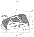
- FIG. 2 is a perspective view illustrating an example of a bypass unit according to the exemplary embodiment.
- FIG. 3 is a view showing the operation of the bypass unit according to the exemplary embodiment.
- the debris filtration apparatus 1 functions to filter out debris from cooling water to be supplied to a target structure required to be cooled, more particularly, to a condenser (not shown) provided in various kinds of power plants (thermoelectric power plants, nuclear power plants, etc.), thus promoting stable operation of the target structure.
- the debris filtration apparatus 1 includes a support unit 100 which is disposed in a chamber housing 2, a screen unit 200 which is disposed between parts of the support unit 100, and a bypass unit 300 which makes cooling water forcibly flow through the debris filtration apparatus 1 when a large amount of debris is deposited on the screen unit 200.
- the chamber housing 2 has a cylindrical shape with a predetermined diameter, in which the support unit 100 is installed.
- the support unit 100 is disposed over the rotor unit 3.
- the rotor unit 3 receives rotational force from a motor (not shown) for rotation and rotates inside the chamber housing 2 at predetermined speed.
- the structure of the rotor unit 3 is as shown in the drawings.
- the support unit 100 includes first to n-th unit supports 100a to 100n which are arranged in a radial shape in a circumferential direction around the center of the support housing 102 disposed on the upper portion of the rotor unit 3.
- the first to n-th unit supports 100a to 100n are spaced apart from each other at the same intervals so that opposite ends of the screen unit 200, which will be described later herein, can be supported by the corresponding unit supports 100a to 100n.
- Each of the first to n-th unit supports 100a to 100n has a plate shape and is fixed at a first end thereof to the support housing 102 and oriented in a radial direction such that a second end thereof faces the circumference of the chamber housing 2, as shown in the drawings.
- the screen unit 200 includes first to n-th unit screens 200a to 200n each of which is individually installed between corresponding ones between the first to n-th unit supports 100a to 100n so as to filter out debris from cooling water.
- a wire net having a specific mesh size to filter out debris from cooling water is used as each of the first to n-th unit screens 200a to 200n.
- a plurality of support frames 202 making close contact with the wire net are longitudinally installed under the wire net.
- each of the first to n-th unit screens 200a to 200n protrudes upwards in a polygonal shape between corresponding ones of the first to n-th unit supports 100a to 100n.
- each of the first to n-th unit screens 200a to 200n is formed to have a polygonal shape, the area with which the unit screen can filter out debris is increased so that a debris removal rate can be increased, whereby the efficiency of the debris filtration apparatus 1 can be enhanced.
- the bypass unit 300 is installed on each of the first to n-th unit screens 200a to 200n.
- the bypass unit 300 selectively rotates the associated one of the first to n-th unit screens 200a to 200n and allows cooling water to flow through the debris filtration apparatus 1. For example, if cooling water cannot be supplied to a condenser installed in a thermoelectric power plant or a load is excessively increased by a large amount of debris deposed on the screen unit 200, the operation of the thermoelectric power plant may have to be interrupted.
- the debris filtration apparatus 1 With regard to the debris filtration apparatus 1, if the bypass unit 300 is operated, cooling water containing debris is supplied to the condenser, so that the cooling efficiency may be reduced, but the operation of the thermoelectric power plant can be continued. Given this, as needed, the debris filtration apparatus 1 operates the bypass unit 300 and thus forcibly rotates the first to n-th unit screens 200a to 200n upward relative to the rotor unit 3, thus ensuring the stable operation of the thermoelectric power plant.
- the present embodiment ensures supply of cooling water even when a large amount of debris is contained in cooling water or even in case of emergency, thus promoting stable power generation.
- the bypass unit 300 is configured such that when a load of a predetermined pressure or more is applied to the screen unit 200 by a large amount of debris deposed on the screen unit 200, a connector 50 is broken so that any one, multiple ones or all of the first to n-th unit screens 200a to 200n that have been fixed are released and rotated in a direction in which cooling water moves, thus allowing a large amount of cooling water to forcibly pass through the debris filtration apparatus. In this way, bypass operation is embodied.
- a first end of each of the first to n-th unit screens is rotatably coupled to the support housing 102 by a hinge 4, and a second end thereof is connected to the chamber housing 2 by a connector 50.
- the connector 50 has a reduced-diameter part 52 in a predetermined portion with respect to an axial direction so that when a load is increased to a predetermined level by a large amount of debris deposited on the screen unit 200, the connector 50 can be broken.
- the connector 50 has a pin shape with a predetermined length, but it may be modified to have another shape. That is, the connector 50 can be changed into various forms rather than being limited to that shown in the drawings.
- the connector 50 may be installed for each of all of the first to n-th unit screens 200a to 200n or restrictively installed for a specific unit screen.
- the number of connectors is not limited, it is preferable that a cooling water supply rate at which the stable operation of the condenser can be ensured be determined in advance and a required number of connectors be used.
- the reduced-diameter part 52 is formed to be reduced in diameter such that it can be broken by a predetermined load or more depending on the material and diameter of the connector 50.
- the minimum diameter of the reduced-diameter part 52 may vary depending on the material and diameter of the connector 50, and the diameter and material of the connector 50 are not limited to specific diameter and material.
- the hinge 4 is fixed at a first end thereof to the support housing 102, and a second end thereof is fixed to the corresponding one of the first to n-th unit screen 200a to 200n.
- the hinge 4 does not necessarily have the structure shown in the drawings but can also have various other structures.
- the connector 50 extends from the outside of the chamber housing 2 toward the corresponding one of the first to n-th unit screen 200a to 200n. Since a large amount of cooling water flows through the chamber housing 2, a separate sealing member (not shown) may be provided around the connector 50.
- the sealing member may be made of either rubber or silicon.
- the first to n-th unit screens 200a to 200n are horizontally disposed between the first to n-th unit supports 100a to 100n.
- Each of the first to n-th unit screens 200a to 200n is configured such that an outer end thereof facing the chamber housing 2 can be rotated around the hinge 4 toward the support housing 102, as designated by the arrow.
- the space in which the unit screen 200 has been horizontally disposed between the corresponding ones of the first to n-th unit supports 100a to 100n is opened to allow a large amount of cooling water to flow via the screen unit 200.
- the bypass unit 300 is connected to the control unit 400 so that the flow rate of cooling water passing through the screen unit 200 of the chamber housing 2 can be controlled.
- a configuration using a cylinder and a piston may be used.
- the bypass unit 300 includes first to n-th unit cylinders 10a to 10n which are disposed outside the chamber housing 2 toward the respective first to n-th unit screens 200a to 200n, and first to n-th unit pistons 20a to 20n which are configured to move forward from the respective first to n-th unit cylinders 10a to 10n toward corresponding insert holes 201 formed in the first to n-th unit screens 200a to 200n or move backward away from the insert holes 201.
- the bypass unit 300 may include a separate fixing member (not shown) for fixing the bypass unit 300 to the chamber housing 2.
- the critical technical characteristics of the present embodiment are that the operation of bypassing cooling water using the first to n-th unit screens 200a to 200n can be easily embodied even without interrupting the operation of the foreign filtration apparatus 1.
- the first to n-th unit cylinders 10a to 10n are arranged in the circumferential direction on the chamber housing 2 in such a way that the first to n-th unit cylinders 10a to 10n face the respective first to n-th unit screens 200a to 200n that are disposed to have a radial shape in the chamber housing 2.
- the first to n-th unit cylinders 10a to 10n are operated by hydraulic, pneumatic, or another type drive source.
- the diameter and shape of each cylinder 10 are not limited.
- a differential pressure sensor 20 is installed in the chamber housing 2 to measure pressures of cooling water passing through the screen unit 200.
- the differential pressure sensor 20 is configured to transmit a sensing signal to the control unit 400.
- the differential pressure sensor 20 is disposed inside the chamber housing 2.
- the differential pressure sensor 20 includes a first sensor 22 which is disposed below the screen unit 200 and configured to measure the pressure of cooling water before passing through the screen unit 200, and a second sensor 24 which is disposed over the screen unit 200 and configured to measure the pressure of the cooling water that has passed through the screen unit 200.
- the first sensor 22 measures the pressure of cooling water before reaching the screen unit 200 and transmits a measured value to the control unit 400.
- the control units 400 receives the measured value and determines whether the pressure of the cooling water before passing through the screen unit 200 is within a range of normal conditions.
- the control unit 400 uses a cooling water pressure range set during an initial design process as a reference for determining whether the pressure of cooling water is within the range of normal conditions.
- control unit 400 receives a pressure signal measured by the second sensor 24 and determines the pressure of cooling water that has passed through the screen unit 200. If cooling water passing through the screen unit 200 contains a large amount of debris, the amount of debris deposited on the screen 200 is gradually increased over time, thus acting as a factor of varying the pressure of cooling water.
- cooling water For example, pieces of debris having different sizes are present in cooling water. Such pieces of debris are filtered out while passing through the screen unit 200. Cooling water containing only a minimized amount of debris is supplied to the condenser (not shown).
- the amount of debris deposed on the first to n-th unit screens 200a to 200n is gradually increased. Therefore, a difference between the pressure of cooling water measured by the second sensor 24 after passing through the screen unit 200 and the pressure of cooling water measured by the first sensor 22 is also increased.
- the control unit 400 receives the pressures measured by the first and second sensors 22 and 24, calculates a difference between the pressures, and determines whether current pressure conditions are within the range of normal conditions or abnormal conditions.
- the abnormal conditions refer to the case where a difference between pressures measured by the first and second sensors 22 and 24 is beyond a preset reference range. This case means that a large amount of debris has been deposed on the screen unit 200.
- the control unit 400 controls the bypass unit 300 such that the first to n-th unit pistons 20a to 20n move forward or backward.
- the displacement of the first to n-th pistons 20a to 20n signals sensed by the first and second sensors 22 and 24 are converted into current signals, and the forward or rearward displacement of each of the first to n-th unit pistons 20a to 20n is determined depending on the current signals.
- Each of the first to n-th unit pistons 20a to 20n is inserted at a front end thereof into the corresponding insert hole 201 by a control command of the control unit 400 so that the associated one of the first to n-th unit screens 200a to 200n is maintained in a horizontal state. This refers to the initial state of each unit piston 20.
- the control unit 400 transmits a control signal to each of the first to n-th unit cylinders 10a to 10n such that the corresponding one of the first to n-th unit pistons 20a to 20n is moved backward toward the outside of the chamber housing 2, the unit cylinder 10 moves the corresponding unit piston 20 backward away from the insert hole (201, refer to FIG. 2 ) of the associated one of the first to n-th unit screens 200a to 200n. Then, the associated one of the first to n-th unit screens 200a to 200n is rotated in a direction in which cooling water flows. In this way, bypass for cooling water is made.
- control unit 400 determines that the amount of debris deposited on the screen unit 200 is comparatively small, and thus controls the first to n-th pistons 20a to 20n such that they are maintained at the initial positions thereof.
- control unit 400 may rotate all of the first to n-th unit screens 200a to 200n or any one or multiple ones of the first to n-th unit screens 200a to 200n. In this way, a rate at which cooling water is supplied to the condenser can be more efficiently controlled.
- differential pressure sensors 20 may be arranged on an inner circumferential surface of the chamber housing 2 at positions spaced apart from each other at regular intervals in the circumferential direction.
- the differential pressure sensors 20 may be disposed at positions facing the respective first to n-th unit screens 200a to 200n.
- control unit 400 can measure the pressures of cooling water passing through each of the first to n-th unit screens 200a to 200n.
- any one of the differential pressure sensors is disposed at a position facing the first unit screen 200a and another one of the different pressure sensors is disposed at a position facing the n-th unit screen 200n
- pressures of cooling water before and after passing through the first unit screen 200a are measured and transmitted to the control unit 400
- pressures of cooling water before and after passing through the n-th unit screen 200n are measured and transmitted to the control unit 400.
- the control unit 400 may receive different input signals depending on the amounts of debris deposited on the respective first to n-th unit screens 200a to 200n. After calculating the signals input from the plurality of differential pressure sensors 20, the control unit 400 can individually control the first to n-th unit screens 200a to 200n.
- all of the first to n-th unit screens 200a to 200n according to the present embodiment may be rotated, or some of them may be individually rotated. As such, controlling the first to n-th unit screens 200a to 200n depending on variation in pressure of cooling water can be further facilitated.
- the bypass unit 300 includes a rotating shaft 310 which is connected to a support frame 202 provided on any one or multiple ones of the first to n-th unit screens 200a to 200n, and a motor unit 320 which provides rotational force to rotate the rotating shaft 310 and thus bypass cooling water.
- the bypass unit 300 can be embodied by merely converting the rotation direction of the rotating shaft 310 without requiring the interruption of the operation of the debris filtration apparatus 1. Therefore, the efficiency of the debris filtration apparatus 1 can be enhanced, and the amount of work imposed on workers to maintain the debris filtration apparatus 1 can be reduced.
- the bypass unit 300 is configured such that the motor unit 320 is controlled, interlocking with the differential pressure sensor 20, by the control unit 400.
- the rate at which cooling water is supplied to the condenser can be controlled. Therefore, cooling water can be supplied to the condenser at the optimum flow rate at which the condenser can be stably operated.
- the debris filtration apparatus according to the present embodiment can promote stable power generation of the power plant and can fundamentally prevent failure or breakage of the condenser, thus assisting expensive equipment such as the thermoe-electric power plant to be efficiently managed.
- the rotating shaft 310 extends to the support housing 102 via the support frame 202.
- the motor unit 320 may comprise a plurality of motor units.
- the motor units 320 are disposed outside the chamber housing 2, so that problems such as a short circuit or corrosion at-tributable to cooling water can be prevented. Thus, the motor units 320 can be used for a long period of time without particular malfunction, and there is little need for repair work.
- each of the first to n-th unit screens 200a to 200n includes a protrusion part 200a1 which protrudes from a central portion of an upper surface of the unit screen between corresponding ones of the first to n-th unit supports 100a to 100n, and an extension part 200a2 which extends in a dome shape downward from each of left and right lower edges of the protrusion part 200a1.
- the extension part 200a2 is inclined downward from an outer end thereof facing the chamber housing 2 to an inner end thereof facing the support housing 102.
- the protrusion part 200a1 protrudes upwards in such a way that a height to which it protrudes toward the chamber housing 2 is greater than a height to which it protrudes toward the support housing 102.
- the support frames 202 that come into close contact with the protrusion part 200a1 are configured such that the sizes thereof are reduced, in proportion to the size of the unit screen, from the chamber housing 2 toward the support housing 102.
- the protrusion part 200a1 changes the flow of cooling water into a vortex form, thus making removal of debris from cooling water more effective. Hence, the amount of debris deposited on the first to n-th unit screens 200a to 200n can be minimized, whereby an unnecessary load applied to the debris filtration apparatus 1 can be minimized. As a result, the durability of the elements of the debris filtration apparatus 1 can be enhanced, and the malfunctioning rate of the debris filtration apparatus 1 can be reduced.
- the first to n-th unit screens 200a to 200n are formed in a dome shape from the circumference defined by outer ends of the first to n-th unit supports 100a to 100n toward the support housing 102.
- the area with which the unit screen can filter out debris from cooling water is increased so that a debris removal rate can be increased, whereby the efficiency of the debris filtration apparatus 1 can be improved, and the amount of unnecessary debris supplied to the condenser can be minimized.
- an angle of the inclination of the first to n-th unit screen 200a to 200n is not limited to a special value, it is preferable that they are formed in a dome shape illustrated in the drawing for the sake of manufacturing.
- the debris filtration apparatus 1a is used to filter out debris from cooling water when the cooling water is supplied to a condenser provided in a thermoelectric power plant.
- the debris filtration apparatus includes a support unit 1000, a screen unit 2000, and a bypass unit 3000.
- the support unit 1000 includes first to n-th unit supports 1000a to 1000n which are arranged, to form a radial shape, in a circumferential direction around a support housing 102 disposed on an upper portion of a rotor unit 3.
- the rotor unit 3 is configured to rotate at a predetermined speed in a chamber housing 2.
- the screen unit 2000 includes first to n-th unit screens 2000a to 2000n which are disposed between the first to n-th unit supports 1000a and 1000n and configured to filter out debris from cooling water.
- the bypass unit 3000 is configured, when a load applied to the screen unit 2000 is increased to a predetermined level by debris deposited on the screen unit 2000, to move each of the first to n-th unit screens 2000a to 2000n toward an upper portion of the support housing 102 and form space for allowing cooling water to flow therethrough.
- the chamber housing 2 has a cylindrical shape with a predetermined diameter, in which the support unit 1000 is installed.
- the support unit 1000 is disposed over the rotor unit 3.
- the rotor unit 3 receives rotational force from a separate motor (not shown) for rotation and rotates inside the chamber housing 2 at predetermined speed.
- the structure of the rotor unit 3 is as shown in the drawings.
- the support unit 1000 includes first to n-th unit supports 1000a to 1000n which are arranged, to form a radial shape, in a circumferential direction around the center of the support housing 102 disposed on the upper portion of the rotor unit 3.
- the first to n-th unit supports 1000a to 1000n are spaced apart from each other at the same intervals and configured to support the screen unit 2000, which will be described in detail later herein.
- Each of the first to n-th unit supports 1000a to 1000n has a plate shape and is fixed at a first end thereof to the support housing 102 and oriented in a radial direction such that a second end thereof faces the circumference of the chamber housing 2, as shown in the drawings.
- the screen unit 2000 includes first to n-th unit screens 2000a to 2000n each of which is individually installed between corresponding ones between the first to n-th unit supports 1000a to 1000n so as to filter out debris from cooling water.
- a wire net having a specific mesh size to filter out debris from cooling water is used as each of the first to n-th unit screens 2000a to 2000n.
- a plurality of support frames 2002 are installed under the wire net in the longitudinal direction of the wire net.
- each of the first to n-th unit screens 2000a to 2000n protrudes upwards in a polygonal shape between corresponding ones of the first to n-th unit supports 1000a to 1000n.
- each of the first to n-th unit screens 2000a to 2000n is formed to have a polygonal shape, the area with which the unit screen can filter out debris is increased so that a debris removal rate can be increased, whereby the efficiency of the debris filtration apparatus 1 can be improved.
- the bypass unit 3000 moves the first to n-th unit screens 2000a to 2000n toward the upper portion of the support housing 1002, thus forming additional space through which cooling water can flow.
- thermoelectric power plant may be interrupted.
- the bypass unit 3000 is operated to move the first to n-th unit screens 2000a to 2000n upward such that even cooling water containing debris can be supplied to the condenser, thus ensuring the stable operation of the thermoelectric power plant.
- the present embodiment is intended to ensure reliable supply of cooling water when a large amount of debris is contained in cooling water or in case of emergency, thus promoting stable power generation.
- the bypass unit 3000 is operated depending on a load applied to a connector 3400. For example, while debris is deposited on the screen unit, pressure by cooling water and pressure resulting from debris deposited on the screen unit are applied together to the connector 3400. Then the connector 3400 is broken instantaneously when the load applied thereto reaches the maximum load that the connector 3400 can withstand.
- the bypass unit 3000 includes a guide bar 3100, a cylindrical movable body 3200, a connection plate 3300, and the connector 3400.
- the guide bar 3100 extends upward from the support housing 1002 with an O-ring 3001 fitted over the guide bar 3100.
- the cylindrical movable body 3200 is provided around the guide bar 3100.
- the connection plate has a first end fixed to the cylindrical movable body 3200, and a second end divided toward the respective first to n-th unit screens 2000a to 2000n and connected to the first to n-th unit screens 2000a to 2000n.
- the connector 3400 is inserted into the cylindrical movable body 3200 from the outside of the cylindrical movable body 3200 toward the guide bar 3100 and configured to be broken when a load applied to the screen unit 2000 is increased to a predetermined level by debris deposited on the screen unit.
- the guide bar 3100 has a diameter less than that of the support housing 1002 and extends a predetermined length upward from a central portion of an upper surface of the support housing 1002.
- the O-ring 3001 is fitted over the guide bar 3100.
- the movable body 3200 has a cylindrical shape and is provided around the guide bar 3100.
- the movable body 3200 extends downward toward the first to n-th unit screens 2000a to 2000n which are separated from each other. Furthermore, the movable body 3200 is coupled to the wire nets forming the upper surfaces of the first to n-th unit screens 2000a to 2000n by the connection plate 3300. Therefore, when the movable body 3200 moves upward in the direction of the arrow, the wire nets are also moved upward along with the movable body 3200, thus forming space through which a large amount of cooling water can flow.
- thermoelectric power plant since the entirety of the screen unit 2000 is moved upward, a large amount of cooling water can be supplied at once to the condenser. When an emergency situation occurs attributable to leakage of cooling water, a large amount of cooling water can be rapidly supplied to the condenser, whereby the stable operation and steady power generation of the thermoelectric power plant can be maintained.
- the guide bar 3100 includes a stop protrusion which is increased in diameter from the upper portion of the guide bar 3100 around which the O-ring 3001 is provided.
- the movable body 3200 is moved upward to the stop protrusion, the movable body 3200 is directly bumped into the O-ring 3001. Therefore, even if an impact is applied to the movable body 3200, damage or deformation thereof can be minimized.
- the O-ring 3001 is formed of rubber in the present embodiment, other materials may be used, or the structure thereof may be modified without being limited to that shown in the drawings.
- the movable body 3200 includes a first movable body 3210 which is configured to be movable upward along the guide bar 3100 and has a disk shape with a predetermined diameter, and a second movable body 3220 which is concentric with the first movable body 3210 and is provided around the circumferential outer surface of the support housing 102.
- the connector 3400 includes a reduced-diameter part 3400a such that the connector 3400 can be broken when a load is increased to a predetermined level by debris deposited on the screen unit 2000.
- the connector 3400 is inserted, from the outside of the first movable body 3200 toward the guide bar 3100, into an insert hole 3002 formed in the first movable body 3200.
- the reduced-diameter part 3400a may be formed in a medial portion or a rear end of the connector 3400 with respect to the longitudinal direction of the connector 3400, but it is not limited to a special position.
- the connector 3400 has a pin shape with a predetermined length, but it may be modified to have another shape. That is, the connector 3400 can be changed into various forms rather than being limited to that shown in the drawings.
- a bypass unit according to yet another embodiment of the present disclosure will be described with reference to the associated drawing.
- the configurations of the guide bar 3100, the movable body 3200 and the connection plate 3300 are the same as those of the bypass unit according to the preceding embodiment.
- the bypass unit 3000 according to the present embodiment is configured such that the entirety of the bypass unit 3000 is moved upward by a motor unit 3600, rather than having a breaking type structure using the connector 3400.
- a rotational force transmission part 3500 is installed on the outer surface of the movable body 3200 so as to receive rotational force from the motor unit 3600 and move the movable body 3200.
- the rotational force transmission part 3500 is able to employ any one of various power transmission structures and is not limited to the structure illustrated in the present embodiment.
- the rotational force transmission part 3500 includes a rack which is longitudinally installed on the movable body 3200 so as to receive rotational force of a pinion 3620 coupled to a front end of a rotating shaft 3610 extending from the motor unit 3600.
- the rack is fixed to the movable body 3200.
- the bypass unit 3000 can be easily operated without interrupting the operation of the debris filtration device.
- a differential pressure sensor (20, refer to FIG. 9 ) is further installed in the chamber housing 2 to measure pressures of cooling water before and after passing through the screen unit 2000.
- the differential pressure sensor 20 is configured to transmit a sensing signal to the control unit 400.
- the control unit 400 operates the motor unit 3600 in the normal or reverse direction, as described above, thus controlling the operation of the bypass unit 3000.
- cooling water is forcibly supplied to a target structure, required to be cooled, by either a manual or automatic method using a bypass unit, thus promoting the stable operation of the target structure, thereby making it possible to stably manage a thermoelectric power plant or a nuclear power plant including the target structure.
- the efficiency of filtering out debris from cooling water passing through the screen unit can be enhanced, whereby the amount of unnecessary debris deposited in the target structure can be minimized. Therefore, the efficiency of the operation of the target structure can be improved.
Landscapes
- Chemical & Material Sciences (AREA)
- Chemical Kinetics & Catalysis (AREA)
- Engineering & Computer Science (AREA)
- Physics & Mathematics (AREA)
- General Engineering & Computer Science (AREA)
- Plasma & Fusion (AREA)
- High Energy & Nuclear Physics (AREA)
- Thermal Sciences (AREA)
- Mechanical Engineering (AREA)
- Filtration Of Liquid (AREA)
- Structure Of Emergency Protection For Nuclear Reactors (AREA)
Abstract
Description
- This application claims priority to Korean Patent Application No(s).
10-2014-0182635 filed on December 17, 2014 - Exemplary embodiments of the present disclosure relates to a debris filtration apparatus which filters out debris from cooling water to be supplied to a target structure, which is required to be cooled by the cooling water, whereby the target structure can be reliably cooled, and which is configured such that debris deposited on a screen unit can be reliably removed, and even when a large amount of debris is deposited on the screen unit, cooling water can be supplied to the target structure so as to ensure stable cooling operation.
- Generally, thermoelectric power plants or nuclear power plants are equipped with apparatuses such as a heat exchanger and a condenser. A pipe unit having a hollow structure is coupled to the heat exchanger or condenser.
- Cooling water is supplied to the heat exchanger or condenser through the pipe unit. Because various kinds of debris may be deposited in the pipe unit and debris may be contained in cooling water, a separate debris removal unit (not shown) is used to remove such debris from cooling water such that only cooling water can be supplied to the heat exchanger or condenser to which the pipe unit is coupled.
- In the conventional techniques, a debris filtration apparatus has been used to filter out debris from cooling water before the cooling water is supplied to a heat exchanger or condenser. However, there are problems in that if a large amount of debris is deposited in the debris filtration apparatus, the debris filtration apparatus may be disabled or cooling water may not be supplied to the heat exchanger or condenser.
- For example, if cooling water cannot be supplied to a condenser installed in a thermo-electric power plant, the operation of the thermoelectric power plant may be partially disabled or the operation of peripheral apparatuses connected to the condenser may be interrupted, thus making power generation impossible. Given this, it is very important to stably and reliably supply cooling water to the condenser.
- Therefore, a method of bypassing cooling water to the condenser when a large amount of debris is deposited in the filtration apparatus is required.
-
- An object of the present disclosure is to provide a debris filtration apparatus which makes it possible to reliably supply cooling water to a heat exchange target structure equipped in various kinds of power plants.
- Another object of the present disclosure is to provide a debris filtration apparatus which is configured such that when bypass operation is required because of a large amount of debris deposited in the debris filtration apparatus, the bypass operation can be easily embodied, thus promoting the stable operation of the target structure and a power plant equipped with the target structure.
- Other objects and advantages of the present disclosure can be understood by the following description, and become apparent with reference to the embodiments of the present disclosure. Also, it is obvious to those skilled in the art to which the present disclosure pertains that the objects and advantages of the present disclosure can be realized by the means as claimed and combinations thereof.
- The object is solved by the features of the independent claims. Preferred embodiments are given in the dependent claims.
- In accordance with one aspect of the present disclosure, A debris filtration apparatus for removing debris from cooling water, comprising: a support unit including first to n-th unit supports arranged, to form a radial form, in a circumferential direction around a support housing disposed on an upper portion of a rotor unit, the rotor unit being configured to rotate at a predetermined speed in a chamber housing; a screen unit including first to n-th unit screens disposed between the first to n-th unit supports and configured to filter out debris from the cooling water; and a bypass unit configured, when a load applied to the screen unit is increased to a predetermined level by deposition of debris on the screen unit, to selectively rotate each of the first to n-th unit screens relative to the support unit and allow flow of the cooling water.
- In the debris filtration apparatus in accordance with an aspect of the present disclosure, the bypass unit may be configured such that: a first end of each of the first to n-th unit screens is rotatably coupled to the support housing by a hinge, and a second end thereof is connected to the chamber housing by a connector; and when a load is increased to the predetermined level by deposition of debris on the screen unit, the connector is broken.
- In the debris filtration apparatus in accordance with another aspect of the present invention, the connector may extend from an outside of the chamber housing toward the corresponding one of the first to n-th unit screens.
- In the debris filtration apparatus in accordance with another aspect of the present disclosure, the connector may include a reduced-diameter part formed such that a diameter thereof is reduced from opposite ends thereof to a medial portion with respect to a longitudinal direction of the connector.
- In the debris filtration apparatus in accordance with another aspect of the present disclosure, the first to n-th unit screens may be oriented in a horizontal direction between the first to n-th unit supports, and each of the first to n-th unit screens may be configured such that an outer end thereof that faces the chamber housing is rotatable around the corresponding hinge toward the support housing.
- In the debris filtration apparatus in accordance with another aspect of the present disclosure, the bypass unit may include: first to n-th unit cylinders disposed outside the chamber housing toward the respective first to n-th unit screens; and first to n-th unit pistons configured to move forward from the respective first to n-th unit cylinders toward corresponding insert holes formed in the first to n-th unit screens or move backward away from the insert holes.
- In the debris filtration apparatus in accordance with another aspect of the present disclosure, the bypass unit may include: a rotating shaft connected at one end thereof to a frame provided on the first to n-th unit screens; and a motor unit configured to selectively rotate the rotating shaft.
- In the debris filtration apparatus in accordance with another aspect of the present disclosure, the motor unit may be configured to rotate the rotating shaft connected to at least one or multiple ones of the first to n-th unit screens.
- The debris filtration apparatus in accordance with another aspect of the present disclosure may further include a differential pressure sensor installed in the chamber housing and configured to measure a pressure of the cooling water that passes through the screen unit.
- In the debris filtration apparatus in accordance with another aspect of the present disclosure, the differential pressure sensor may include: a first sensor disposed below the screen unit and configured to measure a pressure of the cooling water that is in a state before passing through the screen unit; and a second sensor disposed over the screen unit and configured to measure a pressure of the cooling water that has passed through the screen unit.
- In the debris filtration apparatus in accordance with another aspect of the present disclosure, the differential pressure sensor may include a plurality of differential pressure sensors disposed in the chamber housing at positions spaced apart from each other at regular intervals in a circumferential direction.
- In the debris filtration apparatus in accordance with an aspect of the present disclosure, the bypass unit may include: a guide bar extending upward from the support housing, with an O-ring fitted over the guide bar; a cylindrical movable body provided around the guide bar; a connection plate having a first end fixed to the cylindrical movable body, and a second end divided toward the respective first to n-th unit screens and connected to the first to n-th unit screens; and a connector inserted into the cylindrical movable body from an outside of the cylindrical movable body toward the guide bar and configured to be broken when a load applied to the screen unit is increased to the predetermined level by debris deposited on the screen unit.
- In the debris filtration apparatus in accordance with another aspect of the present disclosure, the connector may include a reduced-diameter part formed such that a diameter thereof is reduced from opposite ends thereof to a medial portion with respect to a longitudinal direction of the connector.
- In the debris filtration apparatus in accordance with another aspect of the present disclosure, the bypass unit may include: a guide bar extending upward from the support housing, with an O-ring fitted over the guide bar; a cylindrical movable body provided around the guide bar; a unit connection plate having a first end fixed to the cylindrical movable body, and a second end divided toward the respective first to n-th unit screens and connected to the first to n-th unit screens; and a motor unit configured to transmit a rotational force to a rotational force transmission part fixed on an outer surface of the cylindrical movable body and selectively move the cylindrical movable body upward or downward.
- The debris filtration apparatus in accordance with another aspect of the present disclosure may further include a differential pressure sensor installed in the chamber housing and configured to measure pressures of the cooling water before passing through the screen unit and after having passing through the screen unit.
- The above and other objects, features and other advantages of the present disclosure will be more clearly understood from the following detailed description taken in conjunction with the accompanying drawings, in which:
-
FIG. 1 is a perspective view illustrating a debris filtration apparatus according to an exemplary embodiment. -
FIG. 2 is a perspective view illustrating an example of a bypass unit according to the exemplary embodiment. -
FIG. 3 is a view showing the operation of the bypass unit according to the exemplary embodiment. -
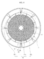
FIG. 4 is a perspective view illustrating a bypass unit according to another exemplary embodiment. - FIGSS. 5 and 6 are views showing the operation of a bypass unit according to another exemplary embodiment.
-
FIGS. 7 and8 are perspective views showing various embodiments of a screen. -
FIG. 9 is a perspective view illustrating a debris filtration apparatus according to yet another exemplary. -
FIGS. 10 and11 is a perspective view illustrating the debris filtration apparatus according to the exemplary embodiment ofFIG. 9 . -
FIG. 12 is a perspective view illustrating a bypass unit according to still another exemplary embodiment. - Hereinafter, exemplary embodiments of a debris filtration apparatus according to the present disclosure will be described with reference to the attached drawings.
FIG. 1 is a perspective view illustrating a debris filtration apparatus according to an exemplary embodiment.FIG. 2 is a perspective view illustrating an example of a bypass unit according to the exemplary embodiment.FIG. 3 is a view showing the operation of the bypass unit according to the exemplary embodiment. - Referring to
FIGS. 1 to 3 , thedebris filtration apparatus 1 functions to filter out debris from cooling water to be supplied to a target structure required to be cooled, more particularly, to a condenser (not shown) provided in various kinds of power plants (thermoelectric power plants, nuclear power plants, etc.), thus promoting stable operation of the target structure. - To achieve the above-mentioned purpose, the
debris filtration apparatus 1 according to the present embodiment includes asupport unit 100 which is disposed in achamber housing 2, ascreen unit 200 which is disposed between parts of thesupport unit 100, and abypass unit 300 which makes cooling water forcibly flow through thedebris filtration apparatus 1 when a large amount of debris is deposited on thescreen unit 200. - The
chamber housing 2 has a cylindrical shape with a predetermined diameter, in which thesupport unit 100 is installed. Thesupport unit 100 is disposed over therotor unit 3. - The
rotor unit 3 receives rotational force from a motor (not shown) for rotation and rotates inside thechamber housing 2 at predetermined speed. The structure of therotor unit 3 is as shown in the drawings. - The
support unit 100 includes first to n-th unit supports 100a to 100n which are arranged in a radial shape in a circumferential direction around the center of thesupport housing 102 disposed on the upper portion of therotor unit 3. The first to n-th unit supports 100a to 100n are spaced apart from each other at the same intervals so that opposite ends of thescreen unit 200, which will be described later herein, can be supported by the corresponding unit supports 100a to 100n. - Each of the first to n-th unit supports 100a to 100n has a plate shape and is fixed at a first end thereof to the
support housing 102 and oriented in a radial direction such that a second end thereof faces the circumference of thechamber housing 2, as shown in the drawings. - The
screen unit 200 includes first to n-th unit screens 200a to 200n each of which is individually installed between corresponding ones between the first to n-th unit supports 100a to 100n so as to filter out debris from cooling water. - A wire net having a specific mesh size to filter out debris from cooling water is used as each of the first to n-
th unit screens 200a to 200n. A plurality of support frames 202 making close contact with the wire net are longitudinally installed under the wire net. For reference, each of the first to n-th unit screens 200a to 200n protrudes upwards in a polygonal shape between corresponding ones of the first to n-th unit supports 100a to 100n. - As such, in the case where each of the first to n-
th unit screens 200a to 200n is formed to have a polygonal shape, the area with which the unit screen can filter out debris is increased so that a debris removal rate can be increased, whereby the efficiency of thedebris filtration apparatus 1 can be enhanced. - The
bypass unit 300 is installed on each of the first to n-th unit screens 200a to 200n. When a large amount of debris deposed on thescreen unit 200 blocks cooling water from smoothly passing through thescreen unit 200 and thus excessively increases a load, thebypass unit 300 selectively rotates the associated one of the first to n-th unit screens 200a to 200n and allows cooling water to flow through thedebris filtration apparatus 1. For example, if cooling water cannot be supplied to a condenser installed in a thermoelectric power plant or a load is excessively increased by a large amount of debris deposed on thescreen unit 200, the operation of the thermoelectric power plant may have to be interrupted. - With regard to the
debris filtration apparatus 1, if thebypass unit 300 is operated, cooling water containing debris is supplied to the condenser, so that the cooling efficiency may be reduced, but the operation of the thermoelectric power plant can be continued. Given this, as needed, thedebris filtration apparatus 1 operates thebypass unit 300 and thus forcibly rotates the first to n-th unit screens 200a to 200n upward relative to therotor unit 3, thus ensuring the stable operation of the thermoelectric power plant. - In this way, the present embodiment ensures supply of cooling water even when a large amount of debris is contained in cooling water or even in case of emergency, thus promoting stable power generation.
- The
bypass unit 300 according to an embodiment of the present disclosure is configured such that when a load of a predetermined pressure or more is applied to thescreen unit 200 by a large amount of debris deposed on thescreen unit 200, aconnector 50 is broken so that any one, multiple ones or all of the first to n-th unit screens 200a to 200n that have been fixed are released and rotated in a direction in which cooling water moves, thus allowing a large amount of cooling water to forcibly pass through the debris filtration apparatus. In this way, bypass operation is embodied. - In more detail, in the
bypass unit 300, a first end of each of the first to n-th unit screens is rotatably coupled to thesupport housing 102 by a hinge 4, and a second end thereof is connected to thechamber housing 2 by aconnector 50. Theconnector 50 has a reduced-diameter part 52 in a predetermined portion with respect to an axial direction so that when a load is increased to a predetermined level by a large amount of debris deposited on thescreen unit 200, theconnector 50 can be broken. - In the present embodiment, the
connector 50 has a pin shape with a predetermined length, but it may be modified to have another shape. That is, theconnector 50 can be changed into various forms rather than being limited to that shown in the drawings. - The
connector 50 may be installed for each of all of the first to n-th unit screens 200a to 200n or restrictively installed for a specific unit screen. Although the number of connectors is not limited, it is preferable that a cooling water supply rate at which the stable operation of the condenser can be ensured be determined in advance and a required number of connectors be used. - The reduced-
diameter part 52 is formed to be reduced in diameter such that it can be broken by a predetermined load or more depending on the material and diameter of theconnector 50. The minimum diameter of the reduced-diameter part 52 may vary depending on the material and diameter of theconnector 50, and the diameter and material of theconnector 50 are not limited to specific diameter and material. - The hinge 4 is fixed at a first end thereof to the
support housing 102, and a second end thereof is fixed to the corresponding one of the first to n-th unit screen 200a to 200n. The hinge 4 does not necessarily have the structure shown in the drawings but can also have various other structures. - The
connector 50 extends from the outside of thechamber housing 2 toward the corresponding one of the first to n-th unit screen 200a to 200n. Since a large amount of cooling water flows through thechamber housing 2, a separate sealing member (not shown) may be provided around theconnector 50. The sealing member may be made of either rubber or silicon. - The first to n-
th unit screens 200a to 200n are horizontally disposed between the first to n-th unit supports 100a to 100n. Each of the first to n-th unit screens 200a to 200n is configured such that an outer end thereof facing thechamber housing 2 can be rotated around the hinge 4 toward thesupport housing 102, as designated by the arrow. When theunit screen 200 is rotated toward thesupport housing 102, the space in which theunit screen 200 has been horizontally disposed between the corresponding ones of the first to n-th unit supports 100a to 100n is opened to allow a large amount of cooling water to flow via thescreen unit 200. - A bypass unit according to another embodiment of the present disclosure will be described with reference to the associated drawings.
- Referring to
FIGS. 1 or4 , unlike the above-mentioned bypass unit that bypasses the flow of cooling water using theconnector 50, thebypass unit 300 according to the present embodiment is connected to thecontrol unit 400 so that the flow rate of cooling water passing through thescreen unit 200 of thechamber housing 2 can be controlled. For example, a configuration using a cylinder and a piston may be used. - In more detail, the
bypass unit 300 includes first to n-th unit cylinders 10a to 10n which are disposed outside thechamber housing 2 toward the respective first to n-th unit screens 200a to 200n, and first to n-th unit pistons 20a to 20n which are configured to move forward from the respective first to n-th unit cylinders 10a to 10n toward corresponding insert holes 201 formed in the first to n-th unit screens 200a to 200n or move backward away from the insert holes 201. For reference, thebypass unit 300 may include a separate fixing member (not shown) for fixing thebypass unit 300 to thechamber housing 2. - The critical technical characteristics of the present embodiment are that the operation of bypassing cooling water using the first to n-
th unit screens 200a to 200n can be easily embodied even without interrupting the operation of theforeign filtration apparatus 1. - The first to n-
th unit cylinders 10a to 10n are arranged in the circumferential direction on thechamber housing 2 in such a way that the first to n-th unit cylinders 10a to 10n face the respective first to n-th unit screens 200a to 200n that are disposed to have a radial shape in thechamber housing 2. The first to n-th unit cylinders 10a to 10n are operated by hydraulic, pneumatic, or another type drive source. The diameter and shape of each cylinder 10 are not limited. - A
differential pressure sensor 20 is installed in thechamber housing 2 to measure pressures of cooling water passing through thescreen unit 200. Thedifferential pressure sensor 20 is configured to transmit a sensing signal to thecontrol unit 400. - The
differential pressure sensor 20 is disposed inside thechamber housing 2. In more detail, thedifferential pressure sensor 20 includes a first sensor 22 which is disposed below thescreen unit 200 and configured to measure the pressure of cooling water before passing through thescreen unit 200, and a second sensor 24 which is disposed over thescreen unit 200 and configured to measure the pressure of the cooling water that has passed through thescreen unit 200. - The first sensor 22 measures the pressure of cooling water before reaching the
screen unit 200 and transmits a measured value to thecontrol unit 400. Thecontrol units 400 receives the measured value and determines whether the pressure of the cooling water before passing through thescreen unit 200 is within a range of normal conditions. - The
control unit 400 uses a cooling water pressure range set during an initial design process as a reference for determining whether the pressure of cooling water is within the range of normal conditions. - Furthermore, the
control unit 400 receives a pressure signal measured by the second sensor 24 and determines the pressure of cooling water that has passed through thescreen unit 200. If cooling water passing through thescreen unit 200 contains a large amount of debris, the amount of debris deposited on thescreen 200 is gradually increased over time, thus acting as a factor of varying the pressure of cooling water. - For example, pieces of debris having different sizes are present in cooling water. Such pieces of debris are filtered out while passing through the
screen unit 200. Cooling water containing only a minimized amount of debris is supplied to the condenser (not shown). - As the time of use of the
screen unit 200 increases, the amount of debris deposed on the first to n-th unit screens 200a to 200n is gradually increased. Therefore, a difference between the pressure of cooling water measured by the second sensor 24 after passing through thescreen unit 200 and the pressure of cooling water measured by the first sensor 22 is also increased. - The
control unit 400 receives the pressures measured by the first and second sensors 22 and 24, calculates a difference between the pressures, and determines whether current pressure conditions are within the range of normal conditions or abnormal conditions. - For instance, the abnormal conditions refer to the case where a difference between pressures measured by the first and second sensors 22 and 24 is beyond a preset reference range. This case means that a large amount of debris has been deposed on the
screen unit 200. - In response to a sensing signal input from the
differential pressure sensor 20, thecontrol unit 400 controls thebypass unit 300 such that the first to n-th unit pistons 20a to 20n move forward or backward. With regard to the displacement of the first to n-th pistons 20a to 20n, signals sensed by the first and second sensors 22 and 24 are converted into current signals, and the forward or rearward displacement of each of the first to n-th unit pistons 20a to 20n is determined depending on the current signals. - Each of the first to n-
th unit pistons 20a to 20n is inserted at a front end thereof into thecorresponding insert hole 201 by a control command of thecontrol unit 400 so that the associated one of the first to n-th unit screens 200a to 200n is maintained in a horizontal state. This refers to the initial state of eachunit piston 20. - In response to a sensing signal input from the
differential pressure sensor 20, when thecontrol unit 400 transmits a control signal to each of the first to n-th unit cylinders 10a to 10n such that the corresponding one of the first to n-th unit pistons 20a to 20n is moved backward toward the outside of thechamber housing 2, the unit cylinder 10 moves thecorresponding unit piston 20 backward away from the insert hole (201, refer toFIG. 2 ) of the associated one of the first to n-th unit screens 200a to 200n. Then, the associated one of the first to n-th unit screens 200a to 200n is rotated in a direction in which cooling water flows. In this way, bypass for cooling water is made. - If a difference between pressures measured by the first and second sensors 22 and 24 is within the range of normal conditions, the
control unit 400 determines that the amount of debris deposited on thescreen unit 200 is comparatively small, and thus controls the first to n-th pistons 20a to 20n such that they are maintained at the initial positions thereof. - Depending on a signal input from the
differential pressure sensor 20, thecontrol unit 400 may rotate all of the first to n-th unit screens 200a to 200n or any one or multiple ones of the first to n-th unit screens 200a to 200n. In this way, a rate at which cooling water is supplied to the condenser can be more efficiently controlled. - For this, in the present embodiment,
differential pressure sensors 20 may be arranged on an inner circumferential surface of thechamber housing 2 at positions spaced apart from each other at regular intervals in the circumferential direction. In this case, thedifferential pressure sensors 20 may be disposed at positions facing the respective first to n-th unit screens 200a to 200n. - In the case where the
differential pressure sensors 20 are disposed at positions facing the respective first to n-th unit screens 200a to 200n, thecontrol unit 400 can measure the pressures of cooling water passing through each of the first to n-th unit screens 200a to 200n. - For example, in the case where any one of the differential pressure sensors is disposed at a position facing the
first unit screen 200a and another one of the different pressure sensors is disposed at a position facing the n-th unit screen 200n, pressures of cooling water before and after passing through thefirst unit screen 200a are measured and transmitted to thecontrol unit 400, and pressures of cooling water before and after passing through the n-th unit screen 200n are measured and transmitted to thecontrol unit 400. - The
control unit 400 may receive different input signals depending on the amounts of debris deposited on the respective first to n-th unit screens 200a to 200n. After calculating the signals input from the plurality ofdifferential pressure sensors 20, thecontrol unit 400 can individually control the first to n-th unit screens 200a to 200n. - Therefore, depending on the pressure of cooling water, all of the first to n-
th unit screens 200a to 200n according to the present embodiment may be rotated, or some of them may be individually rotated. As such, controlling the first to n-th unit screens 200a to 200n depending on variation in pressure of cooling water can be further facilitated. - A bypass unit according to yet another embodiment of the present disclosure will be described with reference to the associated drawings.
- Referring to
FIGS 5 and6 , thebypass unit 300 according to the present embodiment includes arotating shaft 310 which is connected to asupport frame 202 provided on any one or multiple ones of the first to n-th unit screens 200a to 200n, and amotor unit 320 which provides rotational force to rotate therotating shaft 310 and thus bypass cooling water. - Unlike the above-mentioned breaking type bypass unit using the
connector 50, thebypass unit 300 according to the present embodiment can be embodied by merely converting the rotation direction of therotating shaft 310 without requiring the interruption of the operation of thedebris filtration apparatus 1. Therefore, the efficiency of thedebris filtration apparatus 1 can be enhanced, and the amount of work imposed on workers to maintain thedebris filtration apparatus 1 can be reduced. - The
bypass unit 300 is configured such that themotor unit 320 is controlled, interlocking with thedifferential pressure sensor 20, by thecontrol unit 400. Depending on the angle to which therotating shaft 310 is rotated, the rate at which cooling water is supplied to the condenser can be controlled. Therefore, cooling water can be supplied to the condenser at the optimum flow rate at which the condenser can be stably operated. For example, in the case of a thermoelectric power plant, the debris filtration apparatus according to the present embodiment can promote stable power generation of the power plant and can fundamentally prevent failure or breakage of the condenser, thus assisting expensive equipment such as the thermoe-electric power plant to be efficiently managed. - The
rotating shaft 310 extends to thesupport housing 102 via thesupport frame 202. Themotor unit 320 may comprise a plurality of motor units. Themotor units 320 are disposed outside thechamber housing 2, so that problems such as a short circuit or corrosion at-tributable to cooling water can be prevented. Thus, themotor units 320 can be used for a long period of time without particular malfunction, and there is little need for repair work. - The first to n-th unit screens according to the present disclosure can be embodied in various forms, and this will be explained with reference to the drawings.
- Referring to
FIGS. 1 or7 , each of the first to n-th unit screens 200a to 200n according to an embodiment of the present disclosure includes a protrusion part 200a1 which protrudes from a central portion of an upper surface of the unit screen between corresponding ones of the first to n-th unit supports 100a to 100n, and an extension part 200a2 which extends in a dome shape downward from each of left and right lower edges of the protrusion part 200a1. The extension part 200a2 is inclined downward from an outer end thereof facing thechamber housing 2 to an inner end thereof facing thesupport housing 102. - The protrusion part 200a1 protrudes upwards in such a way that a height to which it protrudes toward the
chamber housing 2 is greater than a height to which it protrudes toward thesupport housing 102. The support frames 202 that come into close contact with the protrusion part 200a1 are configured such that the sizes thereof are reduced, in proportion to the size of the unit screen, from thechamber housing 2 toward thesupport housing 102. - Therefore, the flow of cooling water passing through the first to n-th supports 100a to 100n can be induced into turbulent flow rather than steady flow.
- The protrusion part 200a1 changes the flow of cooling water into a vortex form, thus making removal of debris from cooling water more effective. Hence, the amount of debris deposited on the first to n-
th unit screens 200a to 200n can be minimized, whereby an unnecessary load applied to thedebris filtration apparatus 1 can be minimized. As a result, the durability of the elements of thedebris filtration apparatus 1 can be enhanced, and the malfunctioning rate of thedebris filtration apparatus 1 can be reduced. - Referring to
FIG. 8 , the first to n-th unit screens 200a to 200n are formed in a dome shape from the circumference defined by outer ends of the first to n-th unit supports 100a to 100n toward thesupport housing 102. As such, in the case where the first to n-th unit screens 200a to 200n have a dome shape, the area with which the unit screen can filter out debris from cooling water is increased so that a debris removal rate can be increased, whereby the efficiency of thedebris filtration apparatus 1 can be improved, and the amount of unnecessary debris supplied to the condenser can be minimized. - Although an angle of the inclination of the first to n-
th unit screen 200a to 200n is not limited to a special value, it is preferable that they are formed in a dome shape illustrated in the drawing for the sake of manufacturing. - A debris filtration apparatus according to another embodiment of the present disclosure will be described with reference to the associated drawings.
- Referring to
FIG. 9 and10 , thedebris filtration apparatus 1a according to the present embodiment is used to filter out debris from cooling water when the cooling water is supplied to a condenser provided in a thermoelectric power plant. - To achieve the above-mentioned purpose, the debris filtration apparatus according to the present apparatus includes a
support unit 1000, ascreen unit 2000, and abypass unit 3000. Thesupport unit 1000 includes first to n-th unit supports 1000a to 1000n which are arranged, to form a radial shape, in a circumferential direction around asupport housing 102 disposed on an upper portion of arotor unit 3. Therotor unit 3 is configured to rotate at a predetermined speed in achamber housing 2. Thescreen unit 2000 includes first to n-th unit screens 2000a to 2000n which are disposed between the first to n-th unit supports 1000a and 1000n and configured to filter out debris from cooling water. Thebypass unit 3000 is configured, when a load applied to thescreen unit 2000 is increased to a predetermined level by debris deposited on thescreen unit 2000, to move each of the first to n-th unit screens 2000a to 2000n toward an upper portion of thesupport housing 102 and form space for allowing cooling water to flow therethrough. - The
chamber housing 2 has a cylindrical shape with a predetermined diameter, in which thesupport unit 1000 is installed. Thesupport unit 1000 is disposed over therotor unit 3. - The
rotor unit 3 receives rotational force from a separate motor (not shown) for rotation and rotates inside thechamber housing 2 at predetermined speed. The structure of therotor unit 3 is as shown in the drawings. - The
support unit 1000 includes first to n-th unit supports 1000a to 1000n which are arranged, to form a radial shape, in a circumferential direction around the center of thesupport housing 102 disposed on the upper portion of therotor unit 3. The first to n-th unit supports 1000a to 1000n are spaced apart from each other at the same intervals and configured to support thescreen unit 2000, which will be described in detail later herein. - Each of the first to n-th unit supports 1000a to 1000n has a plate shape and is fixed at a first end thereof to the
support housing 102 and oriented in a radial direction such that a second end thereof faces the circumference of thechamber housing 2, as shown in the drawings. - The
screen unit 2000 includes first to n-th unit screens 2000a to 2000n each of which is individually installed between corresponding ones between the first to n-th unit supports 1000a to 1000n so as to filter out debris from cooling water. - A wire net having a specific mesh size to filter out debris from cooling water is used as each of the first to n-
th unit screens 2000a to 2000n. A plurality ofsupport frames 2002 are installed under the wire net in the longitudinal direction of the wire net. For reference, each of the first to n-th unit screens 2000a to 2000n protrudes upwards in a polygonal shape between corresponding ones of the first to n-th unit supports 1000a to 1000n. - As such, in the case where each of the first to n-
th unit screens 2000a to 2000n is formed to have a polygonal shape, the area with which the unit screen can filter out debris is increased so that a debris removal rate can be increased, whereby the efficiency of thedebris filtration apparatus 1 can be improved. - Referring to
FIGS. 10 to 11 , when cooling water cannot smoothly pass through thescreen unit 2000 by a large amount of debris deposited on thescreen unit 2000 and a load is thereby increased, thebypass unit 3000 moves the first to n-th unit screens 2000a to 2000n toward the upper portion of thesupport housing 1002, thus forming additional space through which cooling water can flow. - For example, if the amount of debris contained in cooling water is abnormally increased and thus cooling water cannot be reliably supplied to the condenser, or if a large amount of debris is deposited on the
screen unit 2000 and thus a load is excessively increased, the operation of the thermoelectric power plant may be interrupted. - In this case, the
bypass unit 3000 is operated to move the first to n-th unit screens 2000a to 2000n upward such that even cooling water containing debris can be supplied to the condenser, thus ensuring the stable operation of the thermoelectric power plant. - In this way, the present embodiment is intended to ensure reliable supply of cooling water when a large amount of debris is contained in cooling water or in case of emergency, thus promoting stable power generation.
- The
bypass unit 3000 is operated depending on a load applied to aconnector 3400. For example, while debris is deposited on the screen unit, pressure by cooling water and pressure resulting from debris deposited on the screen unit are applied together to theconnector 3400. Then theconnector 3400 is broken instantaneously when the load applied thereto reaches the maximum load that theconnector 3400 can withstand. - For this, the
bypass unit 3000 includes aguide bar 3100, a cylindricalmovable body 3200, aconnection plate 3300, and theconnector 3400. Theguide bar 3100 extends upward from thesupport housing 1002 with an O-ring 3001 fitted over theguide bar 3100. The cylindricalmovable body 3200 is provided around theguide bar 3100. The connection plate has a first end fixed to the cylindricalmovable body 3200, and a second end divided toward the respective first to n-th unit screens 2000a to 2000n and connected to the first to n-th unit screens 2000a to 2000n. Theconnector 3400 is inserted into the cylindricalmovable body 3200 from the outside of the cylindricalmovable body 3200 toward theguide bar 3100 and configured to be broken when a load applied to thescreen unit 2000 is increased to a predetermined level by debris deposited on the screen unit. - The
guide bar 3100 has a diameter less than that of thesupport housing 1002 and extends a predetermined length upward from a central portion of an upper surface of thesupport housing 1002. The O-ring 3001 is fitted over theguide bar 3100. - The
movable body 3200 has a cylindrical shape and is provided around theguide bar 3100. Themovable body 3200 extends downward toward the first to n-th unit screens 2000a to 2000n which are separated from each other. Furthermore, themovable body 3200 is coupled to the wire nets forming the upper surfaces of the first to n-th unit screens 2000a to 2000n by theconnection plate 3300. Therefore, when themovable body 3200 moves upward in the direction of the arrow, the wire nets are also moved upward along with themovable body 3200, thus forming space through which a large amount of cooling water can flow. - In the case of the present embodiment, since the entirety of the
screen unit 2000 is moved upward, a large amount of cooling water can be supplied at once to the condenser. When an emergency situation occurs attributable to leakage of cooling water, a large amount of cooling water can be rapidly supplied to the condenser, whereby the stable operation and steady power generation of the thermoelectric power plant can be maintained. - The
guide bar 3100 includes a stop protrusion which is increased in diameter from the upper portion of theguide bar 3100 around which the O-ring 3001 is provided. When themovable body 3200 is moved upward to the stop protrusion, themovable body 3200 is directly bumped into the O-ring 3001. Therefore, even if an impact is applied to themovable body 3200, damage or deformation thereof can be minimized. For reference, although the O-ring 3001 is formed of rubber in the present embodiment, other materials may be used, or the structure thereof may be modified without being limited to that shown in the drawings. - The
movable body 3200 includes a firstmovable body 3210 which is configured to be movable upward along theguide bar 3100 and has a disk shape with a predetermined diameter, and a secondmovable body 3220 which is concentric with the firstmovable body 3210 and is provided around the circumferential outer surface of thesupport housing 102. - The
connector 3400 includes a reduced-diameter part 3400a such that theconnector 3400 can be broken when a load is increased to a predetermined level by debris deposited on thescreen unit 2000. Theconnector 3400 is inserted, from the outside of the firstmovable body 3200 toward theguide bar 3100, into aninsert hole 3002 formed in the firstmovable body 3200. - The reduced-
diameter part 3400a may be formed in a medial portion or a rear end of theconnector 3400 with respect to the longitudinal direction of theconnector 3400, but it is not limited to a special position. - In the present embodiment, the
connector 3400 has a pin shape with a predetermined length, but it may be modified to have another shape. That is, theconnector 3400 can be changed into various forms rather than being limited to that shown in the drawings. - A bypass unit according to yet another embodiment of the present disclosure will be described with reference to the associated drawing.
- Referring to
FIG. 12 , in thebypass unit 3000 according to the present embodiment, the configurations of theguide bar 3100, themovable body 3200 and theconnection plate 3300 are the same as those of the bypass unit according to the preceding embodiment. However, thebypass unit 3000 according to the present embodiment is configured such that the entirety of thebypass unit 3000 is moved upward by amotor unit 3600, rather than having a breaking type structure using theconnector 3400. - For this, in the present embodiment, a rotational
force transmission part 3500 is installed on the outer surface of themovable body 3200 so as to receive rotational force from themotor unit 3600 and move themovable body 3200. The rotationalforce transmission part 3500 is able to employ any one of various power transmission structures and is not limited to the structure illustrated in the present embodiment. - The rotational
force transmission part 3500 according to the present embodiment includes a rack which is longitudinally installed on themovable body 3200 so as to receive rotational force of apinion 3620 coupled to a front end of arotating shaft 3610 extending from themotor unit 3600. The rack is fixed to themovable body 3200. Thus, when therotating shaft 3610 is rotated in a clockwise or counterclockwise direction, the entirety of thebypass unit 3000 is moved upward. - After the bypass operation has been completed, when the
rotating shaft 3610 is rotated in the direction opposite to the direction in which it has been rotated to move themovable body 3200 upward, themovable body 3200 is returned to its original position. Therefore, thebypass unit 3000 can be easily operated without interrupting the operation of the debris filtration device. - A differential pressure sensor (20, refer to
FIG. 9 ) is further installed in thechamber housing 2 to measure pressures of cooling water before and after passing through thescreen unit 2000. Thedifferential pressure sensor 20 is configured to transmit a sensing signal to thecontrol unit 400. - The
control unit 400 operates themotor unit 3600 in the normal or reverse direction, as described above, thus controlling the operation of the bypass unit 3000.In various embodiments of the present disclosure, when a large amount of debris is deposited on the screen unit, cooling water is forcibly supplied to a target structure, required to be cooled, by either a manual or automatic method using a bypass unit, thus promoting the stable operation of the target structure, thereby making it possible to stably manage a thermoelectric power plant or a nuclear power plant including the target structure. - Furthermore, according to the embodiments of the present disclosure, the efficiency of filtering out debris from cooling water passing through the screen unit can be enhanced, whereby the amount of unnecessary debris deposited in the target structure can be minimized. Therefore, the efficiency of the operation of the target structure can be improved.
- While the present disclosure has been described with respect to the specific embodiments, it will be apparent to those skilled in the art that various changes and modifications may be made without departing from the scope of the invention as defined in the following claims.
Claims (15)
- A debris filtration apparatus for removing debris from cooling water, comprising:a support unit (100) including first to n-th unit supports (100a-100n) arranged to form a radial form, in a circumferential direction around a support housing (102) disposed on an upper portion of a rotor unit (3), the rotor unit (3) being configured to rotate at a predetermined speed in a chamber housing (2);a screen unit (200) including first to n-th unit screens (200a-200n) disposed between adjacent ones of the first to n-th unit supports (100a-100n) and configured to filter out debris from the cooling water; anda bypass unit (300) configured, when a load applied to the screen unit (200) is increased to a predetermined level by deposition of debris on the screen unit (200), to selectively rotate each of the first to n-th unit screens (200a-200n) relative to the support unit (100) and allow flow of the cooling water.
- The debris filtration apparatus according to claim 1, wherein the bypass unit (300) includes:a hinge (4) that rotatably couples a first end of each of the first to n-th unit screens (200a-200n) to the support housing (102), anda connector (50) that connects a second end of each of the first to n-th unit screens (200a-200n) to the chamber housing (2);wherein the connector (50) is configured to break when a load is increased to the predetermined level by debris deposited on the screen unit (200).
- The debris filtration apparatus according to claim 2, wherein the connector (50) extends from an outside of the chamber housing (2) toward the corresponding one of the first to n-th unit screens (200a-200n).
- The debris filtration apparatus according to claim 2 or 3, wherein the connector (50) comprises a reduced-diameter part (52) formed such that a diameter thereof is reduced from opposite ends thereof to a medial portion with respect to a longitudinal direction of the connector (50).
- The debris filtration apparatus according to any one of the preceding claims, wherein the first to n-th unit screens (200a-200n) are oriented in a horizontal direction between the adjacent ones of the first to n-th unit supports (100a-100n), and each of the first to n-th unit screens (200a-200n) has an outer end that faces the chamber housing (2) and is rotatable around the corresponding hinge toward the support housing (102).
- The debris filtration apparatus according to any one of the preceding claims, wherein the bypass unit (300) comprises:first to n-th unit cylinders (10a-10n) disposed outside the chamber housing (2) toward the respective first to n-th unit screens (200a-200n); andfirst to n-th pistons (20a-20n) configured to move in a first direction from the respective first to n-th unit cylinders (10a-10n) toward respective insert holes (201) formed in the first to n-th unit screens (200a-200n) or move in a second direction away from the insert holes (201).
- The debris filtration apparatus according to any one of the preceding claims, wherein the bypass unit (300) comprises:a rotating shaft (310) connected at one end thereof to a frame (202) provided on the first to n-th screens (200a-200n); anda motor unit (320) configured to selectively rotate the rotating shaft (310).
- The debris filtration apparatus according to claim 7, wherein the motor unit (320) is configured to rotate the rotating shaft (310) connected to at least one or multiple ones of the first to n-th unit screens (200a-200n).
- The debris filtration apparatus according to any one of the preceding claims, further comprising a differential pressure sensor (20) installed in the chamber housing (2) and configured to measure a pressure of the cooling water that passes through the screen unit (200).
- The debris filtration apparatus according to claim 9, wherein the differential pressure sensor (20) comprises:a first sensor (22) disposed below the screen unit (200) and configured to measure a pressure of the cooling water that is in a state before passing through the screen unit (200); anda second sensor (24) disposed over the screen unit (200) and configured to measure a pressure of the cooling water that has passed through the screen unit (200).
- The debris filtration apparatus according to claim 9 or 10, wherein the differential pressure sensor (20) comprises a plurality of differential pressure sensors (20) disposed in the chamber housing (2) at positions spaced apart from each other at regular intervals in a circumferential direction.
- The debris filtration apparatus according to any one of the preceding claims, wherein the bypass unit (3000) comprises:a guide bar (3100) extending upward from the support housing (1002), with an O-ring (3001) fitted over the guide bar (3100);a cylindrical movable body (3200) provided around the guide bar (3100);a connection plate (3300) having a first end fixed to the cylindrical movable body (3200), and a second end divided toward the respective first to n-th unit screens (2000a-2000n) and connected to the first to n-th unit screens (2000a-2000n); anda connector (3400) inserted into the cylindrical movable body (3200) from an outside of the cylindrical movable body (3200) toward the guide bar (3100) and configured to be broken when a load applied to the screen unit (2000) is increased to the predetermined level by deposition of debris on the screen unit (2000).
- The debris filtration apparatus according to claim 12, wherein the connector (3400) comprises a reduced-diameter (52) part formed such that a diameter thereof is reduced from opposite ends thereof to a medial portion with respect to a longitudinal direction of the connector (3400).
- The debris filtration apparatus according to claim 12 or 13, wherein the bypass unit (3000) comprises:a guide bar (3100) extending upward from the support housing (100), with an O-ring (3001) fitted over the guide bar (3100);a cylindrical movable body (3200) provided around the guide bar (3100);a connection plate (3300) having a first end fixed to the cylindrical movable body (3200), and a second end divided toward the respective first to n-th unit screens (2000a-2000n) and connected to the first to n-th unit screens (2000a-2000n); anda motor unit (3600) configured to transmit a rotational force to a rotational force transmitting part fixed on an outer surface of the cylindrical movable body (3200) and selectively move the cylindrical movable body (3200) upward or downward.
- The debris filtration apparatus according to claim 12, 13 or 14, further comprising a differential pressure sensor (20) installed in the chamber housing and configured to measure pressures of the cooling water before passing through the screen unit (2000) and after having passing through the screen unit (2000).
Applications Claiming Priority (1)
| Application Number | Priority Date | Filing Date | Title |
|---|---|---|---|
| KR1020140182635A KR101654996B1 (en) | 2014-12-17 | 2014-12-17 | Debris filtration apparatus |
Publications (2)
| Publication Number | Publication Date |
|---|---|
| EP3041001A1 true EP3041001A1 (en) | 2016-07-06 |
| EP3041001B1 EP3041001B1 (en) | 2020-05-06 |
Family
ID=55527189
Family Applications (1)
| Application Number | Title | Priority Date | Filing Date |
|---|---|---|---|
| EP15200691.2A Active EP3041001B1 (en) | 2014-12-17 | 2015-12-17 | Debris filtration apparatus |
Country Status (3)
| Country | Link |
|---|---|
| US (1) | US9958220B2 (en) |
| EP (1) | EP3041001B1 (en) |
| KR (1) | KR101654996B1 (en) |
Cited By (2)
| Publication number | Priority date | Publication date | Assignee | Title |
|---|---|---|---|---|
| CN107930207A (en) * | 2017-11-29 | 2018-04-20 | 朱清林 | A kind of high speed recycling and processing device for rare earth waste liquid |
| CN108097508A (en) * | 2017-12-10 | 2018-06-01 | 天长市金陵电子有限责任公司 | A kind of high efficiency electrostatic spraying equipment |
Families Citing this family (1)
| Publication number | Priority date | Publication date | Assignee | Title |
|---|---|---|---|---|
| KR102030805B1 (en) * | 2017-12-14 | 2019-10-10 | (주)일정 | Debris removal device |
Citations (4)
| Publication number | Priority date | Publication date | Assignee | Title |
|---|---|---|---|---|
| US4904397A (en) | 1986-11-28 | 1990-02-27 | Taprogge Gesellschaft Mbh | Device for the mechanical cleansing of fluids |
| DE9309126U1 (en) * | 1993-06-18 | 1994-10-27 | Taprogge GmbH, 58300 Wetter | Device for filtering a flowing medium |
| US8501012B2 (en) * | 2008-04-15 | 2013-08-06 | Schlumberger Technology Corporation | Bypass filter apparatus and method |
| EP2719435A1 (en) * | 2012-10-09 | 2014-04-16 | Ovivo Luxembourg S.à.r.l. | Debris filter with splitter box |
Family Cites Families (4)
| Publication number | Priority date | Publication date | Assignee | Title |
|---|---|---|---|---|
| US3483980A (en) * | 1967-01-25 | 1969-12-16 | Atomic Energy Commission | Cold trap filter |
| FR2609644B1 (en) * | 1987-01-16 | 1991-01-04 | Beaudrey & Cie | SELF-CLEANING FILTER TO INSERT ON A PRESSURE PIPE |
| DE102009028356A1 (en) | 2009-08-07 | 2011-02-10 | Robert Bosch Gmbh | Micromechanical component, light deflection device and production method for a micromechanical component and a light deflection device |
| KR101064635B1 (en) * | 2011-02-22 | 2011-09-15 | 삼건세기(주) | Self-cleaning filter |
-
2014
- 2014-12-17 KR KR1020140182635A patent/KR101654996B1/en active Active
-
2015
- 2015-12-16 US US14/971,202 patent/US9958220B2/en active Active
- 2015-12-17 EP EP15200691.2A patent/EP3041001B1/en active Active
Patent Citations (4)
| Publication number | Priority date | Publication date | Assignee | Title |
|---|---|---|---|---|
| US4904397A (en) | 1986-11-28 | 1990-02-27 | Taprogge Gesellschaft Mbh | Device for the mechanical cleansing of fluids |
| DE9309126U1 (en) * | 1993-06-18 | 1994-10-27 | Taprogge GmbH, 58300 Wetter | Device for filtering a flowing medium |
| US8501012B2 (en) * | 2008-04-15 | 2013-08-06 | Schlumberger Technology Corporation | Bypass filter apparatus and method |
| EP2719435A1 (en) * | 2012-10-09 | 2014-04-16 | Ovivo Luxembourg S.à.r.l. | Debris filter with splitter box |
Cited By (2)
| Publication number | Priority date | Publication date | Assignee | Title |
|---|---|---|---|---|
| CN107930207A (en) * | 2017-11-29 | 2018-04-20 | 朱清林 | A kind of high speed recycling and processing device for rare earth waste liquid |
| CN108097508A (en) * | 2017-12-10 | 2018-06-01 | 天长市金陵电子有限责任公司 | A kind of high efficiency electrostatic spraying equipment |
Also Published As
| Publication number | Publication date |
|---|---|
| US20160178294A1 (en) | 2016-06-23 |
| KR20160073825A (en) | 2016-06-27 |
| US9958220B2 (en) | 2018-05-01 |
| KR101654996B1 (en) | 2016-09-06 |
| EP3041001B1 (en) | 2020-05-06 |
Similar Documents
| Publication | Publication Date | Title |
|---|---|---|
| EP3041001B1 (en) | Debris filtration apparatus | |
| JP5538535B2 (en) | Rock drilling rig control system and control method | |
| US9440170B2 (en) | Liquid filter apparatus | |
| US20090178976A1 (en) | Filtering device for liquid filtration | |
| EP3665415B1 (en) | Safety system for a pressure vessel | |
| DK164644B (en) | FILTER JUXTAPOSITION | |
| KR20190129824A (en) | Water filter | |
| EP3717098B1 (en) | Rotary filtering apparatus | |
| US20090078508A1 (en) | Electric motor driven lubrication supply system shutdown system and method | |
| CA2926576A1 (en) | Waste filtration system | |
| CN107224772A (en) | A kind of Rapid replacement formula piping filter for large-scale pipeline | |
| JPH01137191A (en) | In-pipe cleaning device for heat transfer pipe of heat exchanger | |
| JP4866383B2 (en) | Hot forging press with hydraulic control system for wet clutch brake | |
| KR101531858B1 (en) | High pressure cutting oil supplying device for machining center | |
| KR101908959B1 (en) | A lubrication system for intelligent cone crusher | |
| EP2758230B1 (en) | Device for separating material, such as manure, into a liquid fraction and a solid fraction having an adjustable opening for outlet of solid fraction | |
| DE102011011202B4 (en) | Protective device for protecting a pump, in particular for protecting the pump provided in a flow circuit, in particular within a system, from overheating and / or from idling or for protecting the process-technological processing devices provided in the system | |
| CN119982701A (en) | Crawler traction hydraulic station | |
| JP7179285B2 (en) | Tooling fluid supply system | |
| CN202569734U (en) | Adhesive filter | |
| JP5401861B2 (en) | Tread changing device for work vehicle | |
| JP2025528430A (en) | Apparatus for filtering a liquid stream and method of operating the apparatus | |
| JP2012197723A (en) | Wind power generator and method for confirming valve function of wind power generator | |
| JP2020029939A (en) | Drainage discharge device | |
| KR101155528B1 (en) | Apparatus for observing a safety valve bypass element |
Legal Events
| Date | Code | Title | Description |
|---|---|---|---|
| PUAI | Public reference made under article 153(3) epc to a published international application that has entered the european phase |
Free format text: ORIGINAL CODE: 0009012 |
|
| 17P | Request for examination filed |
Effective date: 20151217 |
|
| AK | Designated contracting states |
Kind code of ref document: A1 Designated state(s): AL AT BE BG CH CY CZ DE DK EE ES FI FR GB GR HR HU IE IS IT LI LT LU LV MC MK MT NL NO PL PT RO RS SE SI SK SM TR |
|
| AX | Request for extension of the european patent |
Extension state: BA ME |
|
| RBV | Designated contracting states (corrected) |
Designated state(s): AL AT BE BG CH CY CZ DE DK EE ES FI FR GB GR HR HU IE IS IT LI LT LU LV MC MK MT NL NO PL PT RO RS SE SI SK SM TR |
|
| RAP1 | Party data changed (applicant data changed or rights of an application transferred) |
Owner name: DOOSAN HEAVY INDUSTRIES & CONSTRUCTION CO., LTD. |
|
| GRAP | Despatch of communication of intention to grant a patent |
Free format text: ORIGINAL CODE: EPIDOSNIGR1 |
|
| STAA | Information on the status of an ep patent application or granted ep patent |
Free format text: STATUS: GRANT OF PATENT IS INTENDED |
|
| INTG | Intention to grant announced |
Effective date: 20200114 |
|
| GRAS | Grant fee paid |
Free format text: ORIGINAL CODE: EPIDOSNIGR3 |
|
| GRAA | (expected) grant |
Free format text: ORIGINAL CODE: 0009210 |
|
| STAA | Information on the status of an ep patent application or granted ep patent |
Free format text: STATUS: THE PATENT HAS BEEN GRANTED |
|
| AK | Designated contracting states |
Kind code of ref document: B1 Designated state(s): AL AT BE BG CH CY CZ DE DK EE ES FI FR GB GR HR HU IE IS IT LI LT LU LV MC MK MT NL NO PL PT RO RS SE SI SK SM TR |
|
| REG | Reference to a national code |
Ref country code: GB Ref legal event code: FG4D |
|
| REG | Reference to a national code |
Ref country code: AT Ref legal event code: REF Ref document number: 1268124 Country of ref document: AT Kind code of ref document: T Effective date: 20200515 Ref country code: CH Ref legal event code: EP |
|
| REG | Reference to a national code |
Ref country code: DE Ref legal event code: R096 Ref document number: 602015052085 Country of ref document: DE |
|
| REG | Reference to a national code |
Ref country code: IE Ref legal event code: FG4D |
|
| REG | Reference to a national code |
Ref country code: LT Ref legal event code: MG4D |
|
| REG | Reference to a national code |
Ref country code: NL Ref legal event code: MP Effective date: 20200506 |
|
| PG25 | Lapsed in a contracting state [announced via postgrant information from national office to epo] |
Ref country code: GR Free format text: LAPSE BECAUSE OF FAILURE TO SUBMIT A TRANSLATION OF THE DESCRIPTION OR TO PAY THE FEE WITHIN THE PRESCRIBED TIME-LIMIT Effective date: 20200807 Ref country code: NO Free format text: LAPSE BECAUSE OF FAILURE TO SUBMIT A TRANSLATION OF THE DESCRIPTION OR TO PAY THE FEE WITHIN THE PRESCRIBED TIME-LIMIT Effective date: 20200806 Ref country code: FI Free format text: LAPSE BECAUSE OF FAILURE TO SUBMIT A TRANSLATION OF THE DESCRIPTION OR TO PAY THE FEE WITHIN THE PRESCRIBED TIME-LIMIT Effective date: 20200506 Ref country code: PT Free format text: LAPSE BECAUSE OF FAILURE TO SUBMIT A TRANSLATION OF THE DESCRIPTION OR TO PAY THE FEE WITHIN THE PRESCRIBED TIME-LIMIT Effective date: 20200907 Ref country code: IS Free format text: LAPSE BECAUSE OF FAILURE TO SUBMIT A TRANSLATION OF THE DESCRIPTION OR TO PAY THE FEE WITHIN THE PRESCRIBED TIME-LIMIT Effective date: 20200906 Ref country code: LT Free format text: LAPSE BECAUSE OF FAILURE TO SUBMIT A TRANSLATION OF THE DESCRIPTION OR TO PAY THE FEE WITHIN THE PRESCRIBED TIME-LIMIT Effective date: 20200506 Ref country code: SE Free format text: LAPSE BECAUSE OF FAILURE TO SUBMIT A TRANSLATION OF THE DESCRIPTION OR TO PAY THE FEE WITHIN THE PRESCRIBED TIME-LIMIT Effective date: 20200506 |
|
| PG25 | Lapsed in a contracting state [announced via postgrant information from national office to epo] |
Ref country code: HR Free format text: LAPSE BECAUSE OF FAILURE TO SUBMIT A TRANSLATION OF THE DESCRIPTION OR TO PAY THE FEE WITHIN THE PRESCRIBED TIME-LIMIT Effective date: 20200506 Ref country code: BG Free format text: LAPSE BECAUSE OF FAILURE TO SUBMIT A TRANSLATION OF THE DESCRIPTION OR TO PAY THE FEE WITHIN THE PRESCRIBED TIME-LIMIT Effective date: 20200806 Ref country code: RS Free format text: LAPSE BECAUSE OF FAILURE TO SUBMIT A TRANSLATION OF THE DESCRIPTION OR TO PAY THE FEE WITHIN THE PRESCRIBED TIME-LIMIT Effective date: 20200506 Ref country code: LV Free format text: LAPSE BECAUSE OF FAILURE TO SUBMIT A TRANSLATION OF THE DESCRIPTION OR TO PAY THE FEE WITHIN THE PRESCRIBED TIME-LIMIT Effective date: 20200506 |
|
| REG | Reference to a national code |
Ref country code: AT Ref legal event code: MK05 Ref document number: 1268124 Country of ref document: AT Kind code of ref document: T Effective date: 20200506 |
|
| PG25 | Lapsed in a contracting state [announced via postgrant information from national office to epo] |
Ref country code: AL Free format text: LAPSE BECAUSE OF FAILURE TO SUBMIT A TRANSLATION OF THE DESCRIPTION OR TO PAY THE FEE WITHIN THE PRESCRIBED TIME-LIMIT Effective date: 20200506 Ref country code: NL Free format text: LAPSE BECAUSE OF FAILURE TO SUBMIT A TRANSLATION OF THE DESCRIPTION OR TO PAY THE FEE WITHIN THE PRESCRIBED TIME-LIMIT Effective date: 20200506 |
|
| PG25 | Lapsed in a contracting state [announced via postgrant information from national office to epo] |
Ref country code: DK Free format text: LAPSE BECAUSE OF FAILURE TO SUBMIT A TRANSLATION OF THE DESCRIPTION OR TO PAY THE FEE WITHIN THE PRESCRIBED TIME-LIMIT Effective date: 20200506 Ref country code: ES Free format text: LAPSE BECAUSE OF FAILURE TO SUBMIT A TRANSLATION OF THE DESCRIPTION OR TO PAY THE FEE WITHIN THE PRESCRIBED TIME-LIMIT Effective date: 20200506 Ref country code: AT Free format text: LAPSE BECAUSE OF FAILURE TO SUBMIT A TRANSLATION OF THE DESCRIPTION OR TO PAY THE FEE WITHIN THE PRESCRIBED TIME-LIMIT Effective date: 20200506 Ref country code: EE Free format text: LAPSE BECAUSE OF FAILURE TO SUBMIT A TRANSLATION OF THE DESCRIPTION OR TO PAY THE FEE WITHIN THE PRESCRIBED TIME-LIMIT Effective date: 20200506 Ref country code: SM Free format text: LAPSE BECAUSE OF FAILURE TO SUBMIT A TRANSLATION OF THE DESCRIPTION OR TO PAY THE FEE WITHIN THE PRESCRIBED TIME-LIMIT Effective date: 20200506 Ref country code: CZ Free format text: LAPSE BECAUSE OF FAILURE TO SUBMIT A TRANSLATION OF THE DESCRIPTION OR TO PAY THE FEE WITHIN THE PRESCRIBED TIME-LIMIT Effective date: 20200506 Ref country code: IT Free format text: LAPSE BECAUSE OF FAILURE TO SUBMIT A TRANSLATION OF THE DESCRIPTION OR TO PAY THE FEE WITHIN THE PRESCRIBED TIME-LIMIT Effective date: 20200506 Ref country code: RO Free format text: LAPSE BECAUSE OF FAILURE TO SUBMIT A TRANSLATION OF THE DESCRIPTION OR TO PAY THE FEE WITHIN THE PRESCRIBED TIME-LIMIT Effective date: 20200506 |
|
| REG | Reference to a national code |
Ref country code: DE Ref legal event code: R097 Ref document number: 602015052085 Country of ref document: DE |
|
| PG25 | Lapsed in a contracting state [announced via postgrant information from national office to epo] |
Ref country code: PL Free format text: LAPSE BECAUSE OF FAILURE TO SUBMIT A TRANSLATION OF THE DESCRIPTION OR TO PAY THE FEE WITHIN THE PRESCRIBED TIME-LIMIT Effective date: 20200506 Ref country code: SK Free format text: LAPSE BECAUSE OF FAILURE TO SUBMIT A TRANSLATION OF THE DESCRIPTION OR TO PAY THE FEE WITHIN THE PRESCRIBED TIME-LIMIT Effective date: 20200506 |
|
| PLBE | No opposition filed within time limit |
Free format text: ORIGINAL CODE: 0009261 |
|
| STAA | Information on the status of an ep patent application or granted ep patent |
Free format text: STATUS: NO OPPOSITION FILED WITHIN TIME LIMIT |
|
| 26N | No opposition filed |
Effective date: 20210209 |
|
| PG25 | Lapsed in a contracting state [announced via postgrant information from national office to epo] |
Ref country code: SI Free format text: LAPSE BECAUSE OF FAILURE TO SUBMIT A TRANSLATION OF THE DESCRIPTION OR TO PAY THE FEE WITHIN THE PRESCRIBED TIME-LIMIT Effective date: 20200506 |
|
| REG | Reference to a national code |
Ref country code: CH Ref legal event code: PL |
|
| PG25 | Lapsed in a contracting state [announced via postgrant information from national office to epo] |
Ref country code: MC Free format text: LAPSE BECAUSE OF FAILURE TO SUBMIT A TRANSLATION OF THE DESCRIPTION OR TO PAY THE FEE WITHIN THE PRESCRIBED TIME-LIMIT Effective date: 20200506 |
|
| REG | Reference to a national code |
Ref country code: BE Ref legal event code: MM Effective date: 20201231 |
|
| PG25 | Lapsed in a contracting state [announced via postgrant information from national office to epo] |
Ref country code: LU Free format text: LAPSE BECAUSE OF NON-PAYMENT OF DUE FEES Effective date: 20201217 Ref country code: FR Free format text: LAPSE BECAUSE OF NON-PAYMENT OF DUE FEES Effective date: 20201231 Ref country code: IE Free format text: LAPSE BECAUSE OF NON-PAYMENT OF DUE FEES Effective date: 20201217 |
|
| PG25 | Lapsed in a contracting state [announced via postgrant information from national office to epo] |
Ref country code: LI Free format text: LAPSE BECAUSE OF NON-PAYMENT OF DUE FEES Effective date: 20201231 Ref country code: CH Free format text: LAPSE BECAUSE OF NON-PAYMENT OF DUE FEES Effective date: 20201231 |
|
| PG25 | Lapsed in a contracting state [announced via postgrant information from national office to epo] |
Ref country code: TR Free format text: LAPSE BECAUSE OF FAILURE TO SUBMIT A TRANSLATION OF THE DESCRIPTION OR TO PAY THE FEE WITHIN THE PRESCRIBED TIME-LIMIT Effective date: 20200506 Ref country code: MT Free format text: LAPSE BECAUSE OF FAILURE TO SUBMIT A TRANSLATION OF THE DESCRIPTION OR TO PAY THE FEE WITHIN THE PRESCRIBED TIME-LIMIT Effective date: 20200506 Ref country code: CY Free format text: LAPSE BECAUSE OF FAILURE TO SUBMIT A TRANSLATION OF THE DESCRIPTION OR TO PAY THE FEE WITHIN THE PRESCRIBED TIME-LIMIT Effective date: 20200506 |
|
| PG25 | Lapsed in a contracting state [announced via postgrant information from national office to epo] |
Ref country code: MK Free format text: LAPSE BECAUSE OF FAILURE TO SUBMIT A TRANSLATION OF THE DESCRIPTION OR TO PAY THE FEE WITHIN THE PRESCRIBED TIME-LIMIT Effective date: 20200506 |
|
| PG25 | Lapsed in a contracting state [announced via postgrant information from national office to epo] |
Ref country code: BE Free format text: LAPSE BECAUSE OF NON-PAYMENT OF DUE FEES Effective date: 20201231 |
|
| REG | Reference to a national code |
Ref country code: DE Ref legal event code: R082 Ref document number: 602015052085 Country of ref document: DE Representative=s name: TER MEER STEINMEISTER & PARTNER PATENTANWAELTE, DE |
|
| PGFP | Annual fee paid to national office [announced via postgrant information from national office to epo] |
Ref country code: DE Payment date: 20250930 Year of fee payment: 11 |
|
| PGFP | Annual fee paid to national office [announced via postgrant information from national office to epo] |
Ref country code: GB Payment date: 20251001 Year of fee payment: 11 |