EP3040618B1 - Stove with removable burning chamber - Google Patents
Stove with removable burning chamber Download PDFInfo
- Publication number
- EP3040618B1 EP3040618B1 EP14200531.3A EP14200531A EP3040618B1 EP 3040618 B1 EP3040618 B1 EP 3040618B1 EP 14200531 A EP14200531 A EP 14200531A EP 3040618 B1 EP3040618 B1 EP 3040618B1
- Authority
- EP
- European Patent Office
- Prior art keywords
- stove
- burning chamber
- burning
- connection part
- outer shell
- Prior art date
- Legal status (The legal status is an assumption and is not a legal conclusion. Google has not performed a legal analysis and makes no representation as to the accuracy of the status listed.)
- Active
Links
- 238000010411 cooking Methods 0.000 claims description 9
- 230000000295 complement effect Effects 0.000 claims description 8
- 239000003779 heat-resistant material Substances 0.000 claims description 2
- 239000000446 fuel Substances 0.000 description 5
- 238000010438 heat treatment Methods 0.000 description 4
- 239000000463 material Substances 0.000 description 4
- 238000002485 combustion reaction Methods 0.000 description 3
- 238000004519 manufacturing process Methods 0.000 description 2
- 239000004449 solid propellant Substances 0.000 description 2
- 239000002028 Biomass Substances 0.000 description 1
- 235000021168 barbecue Nutrition 0.000 description 1
- 239000003610 charcoal Substances 0.000 description 1
- 238000000151 deposition Methods 0.000 description 1
- 239000000428 dust Substances 0.000 description 1
- 230000037431 insertion Effects 0.000 description 1
- 238000003780 insertion Methods 0.000 description 1
- 239000003077 lignite Substances 0.000 description 1
- 230000037361 pathway Effects 0.000 description 1
- 239000008188 pellet Substances 0.000 description 1
- 239000002023 wood Substances 0.000 description 1
Images


Classifications
-
- F—MECHANICAL ENGINEERING; LIGHTING; HEATING; WEAPONS; BLASTING
- F24—HEATING; RANGES; VENTILATING
- F24B—DOMESTIC STOVES OR RANGES FOR SOLID FUELS; IMPLEMENTS FOR USE IN CONNECTION WITH STOVES OR RANGES
- F24B1/00—Stoves or ranges
- F24B1/02—Closed stoves
- F24B1/022—Closed stoves easily collapsible or easily removable
-
- F—MECHANICAL ENGINEERING; LIGHTING; HEATING; WEAPONS; BLASTING
- F24—HEATING; RANGES; VENTILATING
- F24B—DOMESTIC STOVES OR RANGES FOR SOLID FUELS; IMPLEMENTS FOR USE IN CONNECTION WITH STOVES OR RANGES
- F24B1/00—Stoves or ranges
- F24B1/18—Stoves with open fires, e.g. fireplaces
- F24B1/181—Free-standing fireplaces, e.g. for mobile homes ; Fireplaces convertible into stoves
-
- F—MECHANICAL ENGINEERING; LIGHTING; HEATING; WEAPONS; BLASTING
- F24—HEATING; RANGES; VENTILATING
- F24B—DOMESTIC STOVES OR RANGES FOR SOLID FUELS; IMPLEMENTS FOR USE IN CONNECTION WITH STOVES OR RANGES
- F24B1/00—Stoves or ranges
- F24B1/18—Stoves with open fires, e.g. fireplaces
- F24B1/182—Stoves with open fires, e.g. fireplaces with additional provisions for cooking
-
- F—MECHANICAL ENGINEERING; LIGHTING; HEATING; WEAPONS; BLASTING
- F24—HEATING; RANGES; VENTILATING
- F24B—DOMESTIC STOVES OR RANGES FOR SOLID FUELS; IMPLEMENTS FOR USE IN CONNECTION WITH STOVES OR RANGES
- F24B1/00—Stoves or ranges
- F24B1/18—Stoves with open fires, e.g. fireplaces
- F24B1/191—Component parts; Accessories
- F24B1/1915—Means for removing ash
-
- F—MECHANICAL ENGINEERING; LIGHTING; HEATING; WEAPONS; BLASTING
- F24—HEATING; RANGES; VENTILATING
- F24B—DOMESTIC STOVES OR RANGES FOR SOLID FUELS; IMPLEMENTS FOR USE IN CONNECTION WITH STOVES OR RANGES
- F24B1/00—Stoves or ranges
- F24B1/18—Stoves with open fires, e.g. fireplaces
- F24B1/191—Component parts; Accessories
- F24B1/197—Hearths
-
- F—MECHANICAL ENGINEERING; LIGHTING; HEATING; WEAPONS; BLASTING
- F24—HEATING; RANGES; VENTILATING
- F24B—DOMESTIC STOVES OR RANGES FOR SOLID FUELS; IMPLEMENTS FOR USE IN CONNECTION WITH STOVES OR RANGES
- F24B1/00—Stoves or ranges
- F24B1/26—Stoves with additional provisions for cooking
Definitions
- the present invention relates to a stove which is suitable for heating and/or cooking.
- Such a stove is generally known.
- Multi-fuel stoves are for example used in small dwellings, such as in developing countries where the same stove is generally used for cooking and heating purposes.
- These stoves have a central burning chamber within an outer shell and have air apertures for controlling the burning of generally solid fuel, like wood -pellets, chips or blocks- or remainders thereof, coals such as charcoal, brown coal or the like.
- the burning is finished the remaining ash is removed from the burning chamber, usually by turning the stove and depositing the ash remains into a safe storage place.
- US 2006/225724 A1 used to delimit claim 1 there from discloses a stove provided with a burning chamber in the form of a fire bucked defining a burning space and having air openings, fig 3A and rows of air openings, whereby at least one row is arranged above the other, an outer shell surrounding the burning chamber, whereby the burning chamber is detachably supported within the outer shell, supporting means holding the burning chamber in an air space at a distance from an inner wall of the outer shell, an electric fan whose air outlet is connected to the air space between the burning chamber and the inner wall, and connector means for inputting electric energy possibly from a battery, solar cells, computer or telephone.
- the inner wall/shell has air openings.
- US 4730597 A discloses a biomass stove provided with a burning chamber in the form of a removable fuel basket with rows of air inlet openings. Of the rows of air openings in the burning chamber a higher row has air openings with a smaller diameter than a lower row. A multi burner stove is disclosed too.
- US 6615821B1 discloses a portable stove having an inner wall, an outer wall and at least one middle wall nested and affixed centrally to a floor for defining multiple pathways for preheating air before it enters a combustion chamber of the stove.
- US 3266478 A discloses a barbecue apparatus having a box like unit with side by side fireboxes. Each firebox has a bottom grate surrounded by perforated walls which have smaller perforations than the grate. A blower may be used for achieving a forced air draft to the boxes.
- WO 2006/081595 A2 discloses a portable cooking apparatus having a suspended combustion vessel, which has a row of apertures for permitting airflow into a solid fuel combustion zone of the chamber.
- a secondary vessel also with apertures is interposed between the vessel and an inner shell for permitting air flow through the apparatus.
- US 3791368 A discloses a multipurpose cooking assembly, which can also be used as a stove.
- a handle attachment structure and a removable handle cooperating therewith are described for handling a top cover of the assembly.
- US 3868943 discloses a cooker stove including a electric heater assembly, which is in electrical contact with a battery, and a blower assembly.
- the blower may be nested in the heater in a position of the cooker. Forced air is blown through space and passages between first, second and third shells to rows of openings formed in a side wall of the stove.
- the burning chamber is a detachable part of the stove and can be taken out of the stove and carried by any person, in order to empty the lose chamber with its ash in a safe storage place. Due to the low weight of the burning chamber emptying is easy and can be done without spilling or the forming of annoying and harmful dust ash clouds.
- the empty usually bucket like burning chamber can then easily be -re-filled with burnable materials, carried to the stove and inserted in the stove, ready for a new burning cycle.
- this does not require any transport of the stove as a whole.
- the distance of the burning chamber, with its air openings, from the inner wall of the outer shell safeguards a continuous flow of air through the air space and the air openings to the burning fuel materials in the burning chamber.
- the stove according to the invention is characterised in that the burning chamber is provided with a flange causing the burning chamber to hang in the air space from the top end of the outer shell.
- the flange may be a radially outward bended flange, preferably provided at the top end of the burning chamber.
- Such a stove having an easy to bend flange can be manufactured in a cost-price friendly way, in particular for use in the developing countries.
- the detachable burning chamber is provided with a connection part at its top end, and that the stove has a handle having a complementary connection part, both connection parts being equipped for being as mutually detachably engaging connection parts.
- the connection part on the burning chamber is an extension
- the connection part of the handle is formed as a wired work, both the extension and the wired work being shaped such that the wired work can be clamped in position around the extension.
- connection part of the handle and its complementary connection part on the burning chamber it is easy to remove and insert the burning chamber from the stove.
- the same handle can be used to move the stove as a whole.
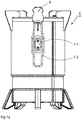
- Figs. 1a and 1b show in a perspective view and an exploded view respectively a stove 1 for heating and/or cooking, which is provided with a burning chamber 2-1, and an outer shell surrounding the burning chamber 2-1.
- the outer shell includes a decorative properly coloured outer wall 3-1 on the outside of the stove 1.
- the outer shell has an inner wall 3-2.
- the outer shell may encompass double walls generally filled with a thermally isolating heat resistant material.
- the burning chamber 2-1 and at least the inner wall 3-2 of the outer shell may be co-axially and will mostly be circular seen in horizontal cross section. For reasons of brevity this circular, co-axial embodiment will be described hereinafter.
- the inner wall 3-2 is hollow and defines an inner air space 4, wherefrom the inserted burning chamber 2-1 can be removed.
- the burning chamber 2-1 is detachably supported in the air space within the inner wall 3-2.
- the wall of the burning chamber 2-1 will generally be provided with air openings 5, capable of letting through air from the air space 4 to the fuel material inside of the burning chamber 2-1, in the condition wherein the chamber 2-1 is lowered in the air space 4 defined by the inner wall 3-2.
- the stove 1 has supporting means here shown as an flange 6 holding the burning chamber in the air space 4 at a distance from an inner wall 3-2 of the outer shell.
- This flange 6 causes the burning chamber 2-1 to hang in the air space 4 from the top end of the outer shell.
- the flange is an annular flange 6 provided at the top end of the burning chamber 2-1.
- a radially outward bended flange 6 is easy to manufacture.
- connection part 7-1 at its top end
- the stove 1 has a handle 8 having a complementary connection part 7-2.
- Both connection parts 7-1 and 7-2 are equipped as mutually detachably engaging connection parts. These parts will here be hooked onto each other as a simple means to remove the burning chamber 2-1 from the air space 4, which eases emptying the burning remains outside the house without transporting the stove 1 as a whole, or to place it back therein possibly holding new materials to be burned.
- connection part 7-1 on the burning chamber 2-1 is an extension
- connection part 7-2 of the handle 8 is formed as a wired work, both as shown in the above mentioned figures.
- the extension and the wired work being shaped such that the wired work can be clamped or tuned in position on or around the extension.
- the same handle 8 used for moving the chamber 2-1 in and out of the stove 1 can be used to transport the stove as a whole if the outer wall 3-1 of the outer shell has an outer wall with a similar connection part 7-1 as the burning chamber 2-1 for being engaged by the complementary connection part 7-2 of that same handle 8.
- the burning chamber 2-1 which defines an inner burning space
- a further burning chamber 2-2 which can be inserted in said inner burning space.
- the chamber 2-2 may also have suitable air openings.
- the nestable further burning chamber 2-2 is provided with a connection part 7-1 at its top end, similar to the part 7-1 on the top end flange 6 of the chamber 2-1 for being engaged by the same complementary connection part 7-2 of the handle 8.
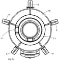
- figs. 2a and 2b show that the upper flanges at the top ends of the burning chambers 2-1 and 2-2 lie in an upper plane of the stove 1.
- the stove 1 is provided with possibly removable braces 9 for clamping an upper flanges supporting ring 10.
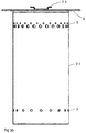
- Figs. 3a and 3b each show main burning chambers 2-1 having air openings 5 and rows of air openings -upper openings in fig. 3b - respectively for application in the stove 1.
- the stove 1 is provided with an electric fan 11 whose air outlet is connected to the air space 4.
- the stove 1 is also provided with connector means 12 for inputting electric energy such as from a battery, solar cells, computer or telephone, either or not provided with solar cells.
- the upper part of the stove 1 may be provided with either or not removable cooking pan supports, which may be the braces 9, whereon a backing or cooking pan can be placed.
- the stove 1 may also hold a suitable grill plate.
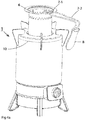
- the stove 1 is provided legs 13, which may be telescopically extendable in order to conveniently lift the stove 1.
Landscapes
- Engineering & Computer Science (AREA)
- Chemical & Material Sciences (AREA)
- Combustion & Propulsion (AREA)
- Mechanical Engineering (AREA)
- General Engineering & Computer Science (AREA)
- Solid-Fuel Combustion (AREA)
Description
- The present invention relates to a stove which is suitable for heating and/or cooking.
- Such a stove is generally known. Multi-fuel stoves are for example used in small dwellings, such as in developing countries where the same stove is generally used for cooking and heating purposes. These stoves have a central burning chamber within an outer shell and have air apertures for controlling the burning of generally solid fuel, like wood -pellets, chips or blocks- or remainders thereof, coals such as charcoal, brown coal or the like. When the burning is finished the remaining ash is removed from the burning chamber, usually by turning the stove and depositing the ash remains into a safe storage place.
-
US 2006/225724 A1 used to delimitclaim 1 there from discloses a stove provided with a burning chamber in the form of a fire bucked defining a burning space and having air openings,fig 3A and rows of air openings, whereby at least one row is arranged above the other, an outer shell surrounding the burning chamber, whereby the burning chamber is detachably supported within the outer shell, supporting means holding the burning chamber in an air space at a distance from an inner wall of the outer shell, an electric fan whose air outlet is connected to the air space between the burning chamber and the inner wall, and connector means for inputting electric energy possibly from a battery, solar cells, computer or telephone. In addition it discloses that the inner wall/shell has air openings. -
US 4730597 A discloses a biomass stove provided with a burning chamber in the form of a removable fuel basket with rows of air inlet openings. Of the rows of air openings in the burning chamber a higher row has air openings with a smaller diameter than a lower row. A multi burner stove is disclosed too. -
US 6615821B1 discloses a portable stove having an inner wall, an outer wall and at least one middle wall nested and affixed centrally to a floor for defining multiple pathways for preheating air before it enters a combustion chamber of the stove. -
US 3266478 A discloses a barbecue apparatus having a box like unit with side by side fireboxes. Each firebox has a bottom grate surrounded by perforated walls which have smaller perforations than the grate. A blower may be used for achieving a forced air draft to the boxes. -
WO 2006/081595 A2 discloses a portable cooking apparatus having a suspended combustion vessel, which has a row of apertures for permitting airflow into a solid fuel combustion zone of the chamber. A secondary vessel also with apertures is interposed between the vessel and an inner shell for permitting air flow through the apparatus. -
US 3791368 A discloses a multipurpose cooking assembly, which can also be used as a stove. A handle attachment structure and a removable handle cooperating therewith are described for handling a top cover of the assembly. -
US 3868943 discloses a cooker stove including a electric heater assembly, which is in electrical contact with a battery, and a blower assembly. The blower may be nested in the heater in a position of the cooker. Forced air is blown through space and passages between first, second and third shells to rows of openings formed in a side wall of the stove. - It is an object of the present invention to provide a light weight multi-fuel stove suitable for heating and/or cooking and equipped to easily remove burning remnants from the stove, which stove has only a few components, is easy to manufacture, maintain and operate, and is cost-price friendly.
- Thereto the stove according to the invention is characterised by the features of
claim 1. - It is an advantage of the stove according to the present invention that the burning chamber is a detachable part of the stove and can be taken out of the stove and carried by any person, in order to empty the lose chamber with its ash in a safe storage place. Due to the low weight of the burning chamber emptying is easy and can be done without spilling or the forming of annoying and harmful dust ash clouds. The empty usually bucket like burning chamber can then easily be -re-filled with burnable materials, carried to the stove and inserted in the stove, ready for a new burning cycle. Advantageously this does not require any transport of the stove as a whole.
- The distance of the burning chamber, with its air openings, from the inner wall of the outer shell safeguards a continuous flow of air through the air space and the air openings to the burning fuel materials in the burning chamber.
- In an embodiment the stove according to the invention is characterised in that the burning chamber is provided with a flange causing the burning chamber to hang in the air space from the top end of the outer shell. The flange may be a radially outward bended flange, preferably provided at the top end of the burning chamber.
- Such a stove having an easy to bend flange can be manufactured in a cost-price friendly way, in particular for use in the developing countries.
- Another embodiment of the stove is characterised in that that the detachable burning chamber is provided with a connection part at its top end, and that the stove has a handle having a complementary connection part, both connection parts being equipped for being as mutually detachably engaging connection parts. In particular the connection part on the burning chamber is an extension, and the connection part of the handle is formed as a wired work, both the extension and the wired work being shaped such that the wired work can be clamped in position around the extension.
- With a simple though effective outline of the connection part of the handle and its complementary connection part on the burning chamber it is easy to remove and insert the burning chamber from the stove.
- With the same handle a further burning chamber possibly present inside the (main) burning chamber can be removed and inserted either individually or simultaneously upon removal or insertion of the main burning chamber.
- Further advantageously the same handle can be used to move the stove as a whole.
- At present the stove according to the invention will be elucidated further together with its additional advantages while reference is being made to the appended drawing, wherein similar components are being referred to by means of the same reference numerals. In the drawing:
-
Figs. 1a and1b show a perspective view and an exploded view respectively of a stove according to the invention; -
Figs. 2a and2b show a side view and an upper view respectively of the stove offigs. 1a /1b ; -
Figs. 3a and3b show views of possible embodiments of the main burning chamber having air openings and rows of air openings respectively for application in the stove according tofig. 1a /1b , and -
Figs. 4a ,4b and4c show how nested burning chambers can be removed individually and/or together from the air space within the inner wall of the stove. -
Figs. 1a and1b show in a perspective view and an exploded view respectively astove 1 for heating and/or cooking, which is provided with a burning chamber 2-1, and an outer shell surrounding the burning chamber 2-1. The outer shell includes a decorative properly coloured outer wall 3-1 on the outside of thestove 1. Within the outer wall 3-1 the outer shell has an inner wall 3-2. - The outer shell may encompass double walls generally filled with a thermally isolating heat resistant material. In practise the burning chamber 2-1 and at least the inner wall 3-2 of the outer shell may be co-axially and will mostly be circular seen in horizontal cross section. For reasons of brevity this circular, co-axial embodiment will be described hereinafter. The inner wall 3-2 is hollow and defines an inner air space 4, wherefrom the inserted burning chamber 2-1 can be removed. The burning chamber 2-1 is detachably supported in the air space within the inner wall 3-2. The wall of the burning chamber 2-1 will generally be provided with
air openings 5, capable of letting through air from the air space 4 to the fuel material inside of the burning chamber 2-1, in the condition wherein the chamber 2-1 is lowered in the air space 4 defined by the inner wall 3-2. - The
stove 1 has supporting means here shown as anflange 6 holding the burning chamber in the air space 4 at a distance from an inner wall 3-2 of the outer shell. Thisflange 6 causes the burning chamber 2-1 to hang in the air space 4 from the top end of the outer shell. For reasons of improved stability the flange is anannular flange 6 provided at the top end of the burning chamber 2-1. A radially outward bendedflange 6 is easy to manufacture. - The detachable burning chamber 2-1 shown in
figs. 2a ,2b ,3a and3c is provided with a connection part 7-1 at its top end, and thestove 1 has ahandle 8 having a complementary connection part 7-2. Both connection parts 7-1 and 7-2 are equipped as mutually detachably engaging connection parts. These parts will here be hooked onto each other as a simple means to remove the burning chamber 2-1 from the air space 4, which eases emptying the burning remains outside the house without transporting thestove 1 as a whole, or to place it back therein possibly holding new materials to be burned. - It is particularly convenient if the connection part 7-1 on the burning chamber 2-1 is an extension, and the connection part 7-2 of the
handle 8 is formed as a wired work, both as shown in the above mentioned figures. Preferably the extension and the wired work being shaped such that the wired work can be clamped or tuned in position on or around the extension. - The
same handle 8 used for moving the chamber 2-1 in and out of thestove 1 can be used to transport the stove as a whole if the outer wall 3-1 of the outer shell has an outer wall with a similar connection part 7-1 as the burning chamber 2-1 for being engaged by the complementary connection part 7-2 of thatsame handle 8. - It may be practical to provide a small fire if the burning chamber 2-1 which defines an inner burning space, is provided with a further burning chamber 2-2, which can be inserted in said inner burning space. The chamber 2-2 may also have suitable air openings. Preferably the nestable further burning chamber 2-2 is provided with a connection part 7-1 at its top end, similar to the part 7-1 on the
top end flange 6 of the chamber 2-1 for being engaged by the same complementary connection part 7-2 of thehandle 8. - In particular
figs. 2a and2b show that the upper flanges at the top ends of the burning chambers 2-1 and 2-2 lie in an upper plane of thestove 1. For constructional ease thestove 1 is provided with possiblyremovable braces 9 for clamping an upperflanges supporting ring 10. -
Figs. 3a and3b each show main burning chambers 2-1 havingair openings 5 and rows of air openings -upper openings infig. 3b - respectively for application in thestove 1. - The particularly outlined rows with smaller openings on top of and in between larger lower openings appeared to be advantageous in terms of achieving a stable burning yielding quietly burning flames.
- The additional drawings of
figs. 4a ,4b and4c show the way wherein only the outer burning chamber 2-1, or only chamber 2-2 or both chambers 2-1 and 2-2 simultaneously can be hooked onto the onehandle 8 by means of the oval shaped connection part 7-2 in combination with the connected holding clip-like parts 7-1 on top of the chambers 2-1 and 2-2. - As schematically also shown in
fig. 1b thestove 1 is provided with anelectric fan 11 whose air outlet is connected to the air space 4. In that case thestove 1 is also provided with connector means 12 for inputting electric energy such as from a battery, solar cells, computer or telephone, either or not provided with solar cells. - The upper part of the
stove 1 may be provided with either or not removable cooking pan supports, which may be thebraces 9, whereon a backing or cooking pan can be placed. Thestove 1 may also hold a suitable grill plate. - As shown the
stove 1 is providedlegs 13, which may be telescopically extendable in order to conveniently lift thestove 1.
Claims (12)
- A stove (1) provided with:- a burning chamber (2-1) defining a burning space and having air openings (5) and rows of air openings, whereby at least one row is arranged above the other,- an outer shell surrounding the burning chamber (2-1), whereby the burning chamber (2-1) is detachably supported within the outer shell,- supporting means (6) holding the burning chamber (2-1) in an air space (4) at a distance from an inner wall (3-2) of the outer shell,- an electric fan (11) whose air outlet is connected to the air space (4) between the burning chamber (2-1) and the inner wall (3-2), and connector means (12) for inputting electric energy possibly from a battery, solar cells, computer or telephone,characterised in that:- of the rows of air openings (5) in the burning chamber (2-1) a higher row has air openings with a smaller diameter than a lower row, and that- the stove (1) is provided with a further burning chamber (2-2) having rows of air openings (5), which further burning chamber (2-2) can be inserted in the burning space of the burning chamber (2-1), such as to form nested burning chambers (2-1, 2-2) which can be removed individually and/or together from the air space within the inner wall (3-2) of the stove (1).
- Stove (1) according to claim 1, characterised in that the burning chamber (2-1; 2-2) is provided with a flange (6) causing the burning chamber (2-1) to hang in the air space (4) from the top end of the outer shell.
- Stove (1) according to claim 2, characterised in that the flange (6) is a radially outward bended flange, preferably provided at the top end of the burning chamber (2-1; 2-2).
- Stove (1) according to any one of the claims 1-3, characterised in that the detachable burning chamber (2-1; 2-2) is provided with a connection part (7-1; 7-1) at its top end, and that the stove (1) has a handle (8) having a complementary connection part (7-2), both connection parts (7-1, 7-2) being equipped for being as mutually detachably engaging connection parts.
- Stove (1) according claim 4, characterised in that the connection part (7-1; 7-1) on the burning chamber (2-1; 2-2) is an extension, and that the connection part (7-2) of the handle (8) is formed as a wired work, both the extension and the wired work being shaped such that the wired work can be clamped in position around the extension.
- Stove (1) according to any one of the claims 4 or 5, characterised in that the outer shell has an outer wall (3-1) having a connection part (7-1) for being engaged by the complementary connection part (7-2) of the handle (8).
- Stove (1) according to any one of the claims 4-6, characterised in that the further burning chamber (2-2) is provided with a connection part (7-1) at its top end for being engaged by the complementary connection part (7-2) of the handle (8).
- Stove (1) according to any one of the claims 1-7, characterised in that the outer shell encompasses double walls (3-1, 3-2) filled with a thermally isolating heat resistant material.
- Stove (1) according to any one of the claims 1-8, characterised in that the upper flanges (6) at the top ends of the burning chambers (2-1, 2-2) lie in an upper plane of the stove, and that the stove (1) is provided with possibly removable braces (9) for clamping an upper flanges supporting ring (10).
- Stove (1) according to claim 9, characterised in that the upper part of the stove (1) is provided with a possibly removable support, such as for a cooking pan or a grill plate.
- Stove (1) according to any one of the claims 4-10, characterised in that only the outer burning chamber (2-1), or only the further burning chamber (2-2) or both chambers (2-1, 2-2) simultaneously can be hooked onto the one handle (8) by means of the oval shaped connection part (7-2) in combination with the connection parts (7-1) which are in the form of holding clip-like parts on top of the chambers (2-1, 2-2).
- Stove (1) according to any one of the claims 1-11, characterised in that the burning chamber/chambers (2-1, 2-2) and the outer shell are co-axially, in particular circularly relative to one another.
Priority Applications (3)
| Application Number | Priority Date | Filing Date | Title |
|---|---|---|---|
| EP14200531.3A EP3040618B8 (en) | 2014-12-30 | 2014-12-30 | Stove with removable burning chamber |
| CN201580072109.9A CN107208898B (en) | 2014-12-30 | 2015-10-28 | Stove with removable combustion chamber |
| PCT/EP2015/075016 WO2016107688A1 (en) | 2014-12-30 | 2015-10-28 | Stove with removable burning chamber |
Applications Claiming Priority (1)
| Application Number | Priority Date | Filing Date | Title |
|---|---|---|---|
| EP14200531.3A EP3040618B8 (en) | 2014-12-30 | 2014-12-30 | Stove with removable burning chamber |
Publications (3)
| Publication Number | Publication Date |
|---|---|
| EP3040618A1 EP3040618A1 (en) | 2016-07-06 |
| EP3040618B1 true EP3040618B1 (en) | 2017-08-23 |
| EP3040618B8 EP3040618B8 (en) | 2017-10-18 |
Family
ID=52292717
Family Applications (1)
| Application Number | Title | Priority Date | Filing Date |
|---|---|---|---|
| EP14200531.3A Active EP3040618B8 (en) | 2014-12-30 | 2014-12-30 | Stove with removable burning chamber |
Country Status (3)
| Country | Link |
|---|---|
| EP (1) | EP3040618B8 (en) |
| CN (1) | CN107208898B (en) |
| WO (1) | WO2016107688A1 (en) |
Families Citing this family (1)
| Publication number | Priority date | Publication date | Assignee | Title |
|---|---|---|---|---|
| CN108561901A (en) * | 2018-04-10 | 2018-09-21 | 佛山市人和科技有限公司 | A kind of Easy assembling glass electric no-smoke furnace |
Citations (1)
| Publication number | Priority date | Publication date | Assignee | Title |
|---|---|---|---|---|
| US8893703B2 (en) * | 2009-11-16 | 2014-11-25 | Colorado State University Research Foundation | Combustion chamber for charcoal stove |
Family Cites Families (8)
| Publication number | Priority date | Publication date | Assignee | Title |
|---|---|---|---|---|
| US3266478A (en) * | 1964-01-10 | 1966-08-16 | James H Booth | Barbecue apparatus |
| US3791368A (en) * | 1972-01-24 | 1974-02-12 | W Hunt | Multipurpose cooking assembly |
| US3868943A (en) * | 1974-06-21 | 1975-03-04 | Hottenroth Fred William | Portable forced draft solid fuel burning cooker |
| US4730597A (en) * | 1986-07-25 | 1988-03-15 | Hottenroth Fred William | Biomass stove |
| US6615821B1 (en) * | 2002-08-13 | 2003-09-09 | Mark S. Stevens Industries, Inc. | Camp stove |
| WO2006081595A2 (en) * | 2005-01-27 | 2006-08-03 | Buzbee (Pty) Ltd | Portable cooking apparatus |
| US20060225724A1 (en) * | 2005-04-06 | 2006-10-12 | Turner Kevin M | Solid-fueled cooking or heating device |
| EP2967255B1 (en) * | 2013-03-15 | 2018-08-08 | Vinett, Kevin | Grill smoker apparatus |
-
2014
- 2014-12-30 EP EP14200531.3A patent/EP3040618B8/en active Active
-
2015
- 2015-10-28 CN CN201580072109.9A patent/CN107208898B/en active Active
- 2015-10-28 WO PCT/EP2015/075016 patent/WO2016107688A1/en active Application Filing
Patent Citations (1)
| Publication number | Priority date | Publication date | Assignee | Title |
|---|---|---|---|---|
| US8893703B2 (en) * | 2009-11-16 | 2014-11-25 | Colorado State University Research Foundation | Combustion chamber for charcoal stove |
Also Published As
| Publication number | Publication date |
|---|---|
| CN107208898B (en) | 2019-02-19 |
| EP3040618B8 (en) | 2017-10-18 |
| CN107208898A (en) | 2017-09-26 |
| EP3040618A1 (en) | 2016-07-06 |
| WO2016107688A1 (en) | 2016-07-07 |
Similar Documents
| Publication | Publication Date | Title |
|---|---|---|
| EP2683280B1 (en) | Barbeque apparatus | |
| US20130112186A1 (en) | Solid fuel cook system | |
| CN107969930A (en) | Pizza oven annex for barbecue grill | |
| EP3040618B1 (en) | Stove with removable burning chamber | |
| JP2015223330A (en) | Charcoal stove | |
| KR200471265Y1 (en) | pellet stove | |
| US20220330750A1 (en) | Fuel grate for a grill | |
| US20150297028A1 (en) | Barbecue grill with rotating fire receptacle | |
| KR200391747Y1 (en) | Barbecue tube use fire with charcoal | |
| KR101336885B1 (en) | Detachable dual cookware | |
| JP3217005U (en) | Cooking aid and cooking utensil using the cooking aid | |
| KR20110010262U (en) | - direct-fired Roaster for a gas stove and a charcoal fire | |
| KR200486112Y1 (en) | Barbecue grill | |
| KR101289550B1 (en) | Ignition device for briquette only | |
| KR101688860B1 (en) | Ignition device using pellet fuel | |
| CN104819486B (en) | A kind of multifunctional assembled multioperation platform fire using in fields stove | |
| US11297979B2 (en) | Charcoal chimney | |
| CN100554790C (en) | Portable cooking apparatus | |
| KR102415462B1 (en) | Multipurpose Fire Pot | |
| US6138661A (en) | Wood coal cook stove | |
| KR101655298B1 (en) | Down stream type grill device with stovepipe | |
| US9854939B2 (en) | Device for grilling and cooking | |
| KR200377597Y1 (en) | Charcoal fire brazier | |
| KR102356371B1 (en) | A boiler having a grill plate | |
| KR101308233B1 (en) | Far-infrared radiation type cooker |
Legal Events
| Date | Code | Title | Description |
|---|---|---|---|
| PUAI | Public reference made under article 153(3) epc to a published international application that has entered the european phase |
Free format text: ORIGINAL CODE: 0009012 |
|
| AK | Designated contracting states |
Kind code of ref document: A1 Designated state(s): AL AT BE BG CH CY CZ DE DK EE ES FI FR GB GR HR HU IE IS IT LI LT LU LV MC MK MT NL NO PL PT RO RS SE SI SK SM TR |
|
| AX | Request for extension of the european patent |
Extension state: BA ME |
|
| 17P | Request for examination filed |
Effective date: 20170104 |
|
| RBV | Designated contracting states (corrected) |
Designated state(s): AL AT BE BG CH CY CZ DE DK EE ES FI FR GB GR HR HU IE IS IT LI LT LU LV MC MK MT NL NO PL PT RO RS SE SI SK SM TR |
|
| GRAP | Despatch of communication of intention to grant a patent |
Free format text: ORIGINAL CODE: EPIDOSNIGR1 |
|
| INTG | Intention to grant announced |
Effective date: 20170616 |
|
| GRAS | Grant fee paid |
Free format text: ORIGINAL CODE: EPIDOSNIGR3 |
|
| GRAA | (expected) grant |
Free format text: ORIGINAL CODE: 0009210 |
|
| AK | Designated contracting states |
Kind code of ref document: B1 Designated state(s): AL AT BE BG CH CY CZ DE DK EE ES FI FR GB GR HR HU IE IS IT LI LT LU LV MC MK MT NL NO PL PT RO RS SE SI SK SM TR |
|
| REG | Reference to a national code |
Ref country code: GB Ref legal event code: FG4D |
|
| REG | Reference to a national code |
Ref country code: CH Ref legal event code: EP |
|
| RAP2 | Party data changed (patent owner data changed or rights of a patent transferred) |
Owner name: MIMI MOTO HOLDING B.V. |
|
| REG | Reference to a national code |
Ref country code: AT Ref legal event code: REF Ref document number: 921758 Country of ref document: AT Kind code of ref document: T Effective date: 20170915 |
|
| REG | Reference to a national code |
Ref country code: IE Ref legal event code: FG4D |
|
| REG | Reference to a national code |
Ref country code: DE Ref legal event code: R096 Ref document number: 602014013445 Country of ref document: DE |
|
| REG | Reference to a national code |
Ref country code: NL Ref legal event code: FP |
|
| REG | Reference to a national code |
Ref country code: LT Ref legal event code: MG4D |
|
| REG | Reference to a national code |
Ref country code: AT Ref legal event code: MK05 Ref document number: 921758 Country of ref document: AT Kind code of ref document: T Effective date: 20170823 |
|
| PG25 | Lapsed in a contracting state [announced via postgrant information from national office to epo] |
Ref country code: FI Free format text: LAPSE BECAUSE OF FAILURE TO SUBMIT A TRANSLATION OF THE DESCRIPTION OR TO PAY THE FEE WITHIN THE PRESCRIBED TIME-LIMIT Effective date: 20170823 Ref country code: AT Free format text: LAPSE BECAUSE OF FAILURE TO SUBMIT A TRANSLATION OF THE DESCRIPTION OR TO PAY THE FEE WITHIN THE PRESCRIBED TIME-LIMIT Effective date: 20170823 Ref country code: LT Free format text: LAPSE BECAUSE OF FAILURE TO SUBMIT A TRANSLATION OF THE DESCRIPTION OR TO PAY THE FEE WITHIN THE PRESCRIBED TIME-LIMIT Effective date: 20170823 Ref country code: SE Free format text: LAPSE BECAUSE OF FAILURE TO SUBMIT A TRANSLATION OF THE DESCRIPTION OR TO PAY THE FEE WITHIN THE PRESCRIBED TIME-LIMIT Effective date: 20170823 Ref country code: HR Free format text: LAPSE BECAUSE OF FAILURE TO SUBMIT A TRANSLATION OF THE DESCRIPTION OR TO PAY THE FEE WITHIN THE PRESCRIBED TIME-LIMIT Effective date: 20170823 Ref country code: NO Free format text: LAPSE BECAUSE OF FAILURE TO SUBMIT A TRANSLATION OF THE DESCRIPTION OR TO PAY THE FEE WITHIN THE PRESCRIBED TIME-LIMIT Effective date: 20171123 |
|
| PG25 | Lapsed in a contracting state [announced via postgrant information from national office to epo] |
Ref country code: PL Free format text: LAPSE BECAUSE OF FAILURE TO SUBMIT A TRANSLATION OF THE DESCRIPTION OR TO PAY THE FEE WITHIN THE PRESCRIBED TIME-LIMIT Effective date: 20170823 Ref country code: GR Free format text: LAPSE BECAUSE OF FAILURE TO SUBMIT A TRANSLATION OF THE DESCRIPTION OR TO PAY THE FEE WITHIN THE PRESCRIBED TIME-LIMIT Effective date: 20171124 Ref country code: BG Free format text: LAPSE BECAUSE OF FAILURE TO SUBMIT A TRANSLATION OF THE DESCRIPTION OR TO PAY THE FEE WITHIN THE PRESCRIBED TIME-LIMIT Effective date: 20171123 Ref country code: RS Free format text: LAPSE BECAUSE OF FAILURE TO SUBMIT A TRANSLATION OF THE DESCRIPTION OR TO PAY THE FEE WITHIN THE PRESCRIBED TIME-LIMIT Effective date: 20170823 Ref country code: IS Free format text: LAPSE BECAUSE OF FAILURE TO SUBMIT A TRANSLATION OF THE DESCRIPTION OR TO PAY THE FEE WITHIN THE PRESCRIBED TIME-LIMIT Effective date: 20171223 Ref country code: LV Free format text: LAPSE BECAUSE OF FAILURE TO SUBMIT A TRANSLATION OF THE DESCRIPTION OR TO PAY THE FEE WITHIN THE PRESCRIBED TIME-LIMIT Effective date: 20170823 Ref country code: ES Free format text: LAPSE BECAUSE OF FAILURE TO SUBMIT A TRANSLATION OF THE DESCRIPTION OR TO PAY THE FEE WITHIN THE PRESCRIBED TIME-LIMIT Effective date: 20170823 |
|
| PG25 | Lapsed in a contracting state [announced via postgrant information from national office to epo] |
Ref country code: CZ Free format text: LAPSE BECAUSE OF FAILURE TO SUBMIT A TRANSLATION OF THE DESCRIPTION OR TO PAY THE FEE WITHIN THE PRESCRIBED TIME-LIMIT Effective date: 20170823 Ref country code: RO Free format text: LAPSE BECAUSE OF FAILURE TO SUBMIT A TRANSLATION OF THE DESCRIPTION OR TO PAY THE FEE WITHIN THE PRESCRIBED TIME-LIMIT Effective date: 20170823 Ref country code: DK Free format text: LAPSE BECAUSE OF FAILURE TO SUBMIT A TRANSLATION OF THE DESCRIPTION OR TO PAY THE FEE WITHIN THE PRESCRIBED TIME-LIMIT Effective date: 20170823 |
|
| REG | Reference to a national code |
Ref country code: DE Ref legal event code: R097 Ref document number: 602014013445 Country of ref document: DE |
|
| PG25 | Lapsed in a contracting state [announced via postgrant information from national office to epo] |
Ref country code: SK Free format text: LAPSE BECAUSE OF FAILURE TO SUBMIT A TRANSLATION OF THE DESCRIPTION OR TO PAY THE FEE WITHIN THE PRESCRIBED TIME-LIMIT Effective date: 20170823 Ref country code: SM Free format text: LAPSE BECAUSE OF FAILURE TO SUBMIT A TRANSLATION OF THE DESCRIPTION OR TO PAY THE FEE WITHIN THE PRESCRIBED TIME-LIMIT Effective date: 20170823 Ref country code: EE Free format text: LAPSE BECAUSE OF FAILURE TO SUBMIT A TRANSLATION OF THE DESCRIPTION OR TO PAY THE FEE WITHIN THE PRESCRIBED TIME-LIMIT Effective date: 20170823 Ref country code: IT Free format text: LAPSE BECAUSE OF FAILURE TO SUBMIT A TRANSLATION OF THE DESCRIPTION OR TO PAY THE FEE WITHIN THE PRESCRIBED TIME-LIMIT Effective date: 20170823 |
|
| PLBE | No opposition filed within time limit |
Free format text: ORIGINAL CODE: 0009261 |
|
| STAA | Information on the status of an ep patent application or granted ep patent |
Free format text: STATUS: NO OPPOSITION FILED WITHIN TIME LIMIT |
|
| REG | Reference to a national code |
Ref country code: DE Ref legal event code: R119 Ref document number: 602014013445 Country of ref document: DE |
|
| REG | Reference to a national code |
Ref country code: CH Ref legal event code: PL |
|
| 26N | No opposition filed |
Effective date: 20180524 |
|
| PG25 | Lapsed in a contracting state [announced via postgrant information from national office to epo] |
Ref country code: SI Free format text: LAPSE BECAUSE OF FAILURE TO SUBMIT A TRANSLATION OF THE DESCRIPTION OR TO PAY THE FEE WITHIN THE PRESCRIBED TIME-LIMIT Effective date: 20170823 |
|
| PG25 | Lapsed in a contracting state [announced via postgrant information from national office to epo] |
Ref country code: MT Free format text: LAPSE BECAUSE OF NON-PAYMENT OF DUE FEES Effective date: 20171230 Ref country code: LU Free format text: LAPSE BECAUSE OF NON-PAYMENT OF DUE FEES Effective date: 20171230 |
|
| REG | Reference to a national code |
Ref country code: FR Ref legal event code: ST Effective date: 20180831 |
|
| REG | Reference to a national code |
Ref country code: IE Ref legal event code: MM4A |
|
| REG | Reference to a national code |
Ref country code: BE Ref legal event code: MM Effective date: 20171231 |
|
| PG25 | Lapsed in a contracting state [announced via postgrant information from national office to epo] |
Ref country code: IE Free format text: LAPSE BECAUSE OF NON-PAYMENT OF DUE FEES Effective date: 20171230 Ref country code: FR Free format text: LAPSE BECAUSE OF NON-PAYMENT OF DUE FEES Effective date: 20180102 Ref country code: DE Free format text: LAPSE BECAUSE OF NON-PAYMENT OF DUE FEES Effective date: 20180703 |
|
| PG25 | Lapsed in a contracting state [announced via postgrant information from national office to epo] |
Ref country code: LI Free format text: LAPSE BECAUSE OF NON-PAYMENT OF DUE FEES Effective date: 20171231 Ref country code: BE Free format text: LAPSE BECAUSE OF NON-PAYMENT OF DUE FEES Effective date: 20171231 Ref country code: CH Free format text: LAPSE BECAUSE OF NON-PAYMENT OF DUE FEES Effective date: 20171231 |
|
| PG25 | Lapsed in a contracting state [announced via postgrant information from national office to epo] |
Ref country code: MC Free format text: LAPSE BECAUSE OF FAILURE TO SUBMIT A TRANSLATION OF THE DESCRIPTION OR TO PAY THE FEE WITHIN THE PRESCRIBED TIME-LIMIT Effective date: 20170823 Ref country code: HU Free format text: LAPSE BECAUSE OF FAILURE TO SUBMIT A TRANSLATION OF THE DESCRIPTION OR TO PAY THE FEE WITHIN THE PRESCRIBED TIME-LIMIT; INVALID AB INITIO Effective date: 20141230 |
|
| GBPC | Gb: european patent ceased through non-payment of renewal fee |
Effective date: 20181230 |
|
| PG25 | Lapsed in a contracting state [announced via postgrant information from national office to epo] |
Ref country code: CY Free format text: LAPSE BECAUSE OF FAILURE TO SUBMIT A TRANSLATION OF THE DESCRIPTION OR TO PAY THE FEE WITHIN THE PRESCRIBED TIME-LIMIT Effective date: 20170823 |
|
| PG25 | Lapsed in a contracting state [announced via postgrant information from national office to epo] |
Ref country code: MK Free format text: LAPSE BECAUSE OF FAILURE TO SUBMIT A TRANSLATION OF THE DESCRIPTION OR TO PAY THE FEE WITHIN THE PRESCRIBED TIME-LIMIT Effective date: 20170823 |
|
| PG25 | Lapsed in a contracting state [announced via postgrant information from national office to epo] |
Ref country code: GB Free format text: LAPSE BECAUSE OF NON-PAYMENT OF DUE FEES Effective date: 20181230 |
|
| PG25 | Lapsed in a contracting state [announced via postgrant information from national office to epo] |
Ref country code: TR Free format text: LAPSE BECAUSE OF FAILURE TO SUBMIT A TRANSLATION OF THE DESCRIPTION OR TO PAY THE FEE WITHIN THE PRESCRIBED TIME-LIMIT Effective date: 20170823 |
|
| PG25 | Lapsed in a contracting state [announced via postgrant information from national office to epo] |
Ref country code: PT Free format text: LAPSE BECAUSE OF FAILURE TO SUBMIT A TRANSLATION OF THE DESCRIPTION OR TO PAY THE FEE WITHIN THE PRESCRIBED TIME-LIMIT Effective date: 20170823 |
|
| PG25 | Lapsed in a contracting state [announced via postgrant information from national office to epo] |
Ref country code: AL Free format text: LAPSE BECAUSE OF FAILURE TO SUBMIT A TRANSLATION OF THE DESCRIPTION OR TO PAY THE FEE WITHIN THE PRESCRIBED TIME-LIMIT Effective date: 20170823 |
|
| PGFP | Annual fee paid to national office [announced via postgrant information from national office to epo] |
Ref country code: NL Payment date: 20231226 Year of fee payment: 10 |