EP2967255B1 - Grill smoker apparatus - Google Patents
Grill smoker apparatus Download PDFInfo
- Publication number
- EP2967255B1 EP2967255B1 EP14762538.8A EP14762538A EP2967255B1 EP 2967255 B1 EP2967255 B1 EP 2967255B1 EP 14762538 A EP14762538 A EP 14762538A EP 2967255 B1 EP2967255 B1 EP 2967255B1
- Authority
- EP
- European Patent Office
- Prior art keywords
- carrier
- concentrator
- container
- vent
- base
- Prior art date
- Legal status (The legal status is an assumption and is not a legal conclusion. Google has not performed a legal analysis and makes no representation as to the accuracy of the status listed.)
- Not-in-force
Links
- 239000003779 heat-resistant material Substances 0.000 claims description 4
- 239000000779 smoke Substances 0.000 description 94
- 239000000463 material Substances 0.000 description 57
- 235000013305 food Nutrition 0.000 description 27
- 230000000391 smoking effect Effects 0.000 description 22
- 238000010411 cooking Methods 0.000 description 17
- 239000002023 wood Substances 0.000 description 11
- 239000000796 flavoring agent Substances 0.000 description 6
- 235000019634 flavors Nutrition 0.000 description 6
- 239000008188 pellet Substances 0.000 description 6
- 239000003610 charcoal Substances 0.000 description 5
- 238000002485 combustion reaction Methods 0.000 description 5
- 238000004519 manufacturing process Methods 0.000 description 5
- 235000013372 meat Nutrition 0.000 description 4
- 238000000034 method Methods 0.000 description 4
- 239000000446 fuel Substances 0.000 description 3
- 238000010438 heat treatment Methods 0.000 description 3
- 239000002184 metal Substances 0.000 description 3
- 229910052751 metal Inorganic materials 0.000 description 3
- 230000000717 retained effect Effects 0.000 description 3
- ATUOYWHBWRKTHZ-UHFFFAOYSA-N Propane Chemical compound CCC ATUOYWHBWRKTHZ-UHFFFAOYSA-N 0.000 description 2
- 235000021168 barbecue Nutrition 0.000 description 2
- 230000001419 dependent effect Effects 0.000 description 2
- 238000005553 drilling Methods 0.000 description 2
- 238000009434 installation Methods 0.000 description 2
- 239000000203 mixture Substances 0.000 description 2
- 241000238631 Hexapoda Species 0.000 description 1
- 241001465754 Metazoa Species 0.000 description 1
- 229910000831 Steel Inorganic materials 0.000 description 1
- 239000000919 ceramic Substances 0.000 description 1
- 238000007796 conventional method Methods 0.000 description 1
- 230000007797 corrosion Effects 0.000 description 1
- 238000005260 corrosion Methods 0.000 description 1
- 239000012530 fluid Substances 0.000 description 1
- 230000005484 gravity Effects 0.000 description 1
- 239000007788 liquid Substances 0.000 description 1
- 150000002739 metals Chemical class 0.000 description 1
- 230000004048 modification Effects 0.000 description 1
- 238000012986 modification Methods 0.000 description 1
- 239000010813 municipal solid waste Substances 0.000 description 1
- 229910052573 porcelain Inorganic materials 0.000 description 1
- 239000001294 propane Substances 0.000 description 1
- 230000000630 rising effect Effects 0.000 description 1
- 239000007787 solid Substances 0.000 description 1
- 229910001220 stainless steel Inorganic materials 0.000 description 1
- 239000010935 stainless steel Substances 0.000 description 1
- 239000010959 steel Substances 0.000 description 1
- 239000000037 vitreous enamel Substances 0.000 description 1
- XLYOFNOQVPJJNP-UHFFFAOYSA-N water Substances O XLYOFNOQVPJJNP-UHFFFAOYSA-N 0.000 description 1
Images


Classifications
-
- A—HUMAN NECESSITIES
- A23—FOODS OR FOODSTUFFS; TREATMENT THEREOF, NOT COVERED BY OTHER CLASSES
- A23B—PRESERVING, e.g. BY CANNING, MEAT, FISH, EGGS, FRUIT, VEGETABLES, EDIBLE SEEDS; CHEMICAL RIPENING OF FRUIT OR VEGETABLES; THE PRESERVED, RIPENED, OR CANNED PRODUCTS
- A23B4/00—General methods for preserving meat, sausages, fish or fish products
- A23B4/044—Smoking; Smoking devices
- A23B4/052—Smoke generators ; Smoking apparatus
-
- Y—GENERAL TAGGING OF NEW TECHNOLOGICAL DEVELOPMENTS; GENERAL TAGGING OF CROSS-SECTIONAL TECHNOLOGIES SPANNING OVER SEVERAL SECTIONS OF THE IPC; TECHNICAL SUBJECTS COVERED BY FORMER USPC CROSS-REFERENCE ART COLLECTIONS [XRACs] AND DIGESTS
- Y02—TECHNOLOGIES OR APPLICATIONS FOR MITIGATION OR ADAPTATION AGAINST CLIMATE CHANGE
- Y02A—TECHNOLOGIES FOR ADAPTATION TO CLIMATE CHANGE
- Y02A40/00—Adaptation technologies in agriculture, forestry, livestock or agroalimentary production
- Y02A40/90—Adaptation technologies in agriculture, forestry, livestock or agroalimentary production in food processing or handling, e.g. food conservation
Definitions
- the present disclosure relates generally to an apparatus for smoking food and more particularly to an apparatus that provides a smoking apparatus for positioning inside a cooking enclosure such as a grill or smoker for smoking food.
- Some food smoking devices include self-contained enclosures in which the food to be smoked is placed.
- the enclosures can be closed and sealed to contain smoke that imparts flavor to the food, usually with a lid.
- a support structure such as a grid or platform, on which the meat or other food is placed.
- Smoke producing material such as charcoal or wood is also placed in the enclosure and ignited.
- the smoke producing materials are often wood chips soaked in water to facilitate the creation of the smoke, wood pellets designed to burn or smolder when a heat source is applied to the pellets, or liquids that render a flavored smoke when heated.
- Conventional smokers of this nature are generally large enclosures having a generally cylindrical shape. Most conventional smokers of this nature also rely on burning material for heat and smoke production, as opposed to combustion of flammable gas such as propane.
- Still others have developed containers for holding smoke producing chips for placing on a grilling surface such as a grid, grate or platform, or directly on gas burners or charcoal.
- a grilling surface such as a grid, grate or platform, or directly on gas burners or charcoal.
- These types of containers include open trays or covered pans that may be vented to permit smoke from the heated smoke producing material to escape.
- the food is placed on the cooking surface of the grill, and the smoke is contained by closing the cover on the grill, which may or may not allow for the regulation of the amount of smoke within the enclosed cooking area by adjustable vents in the grill cover.
- These devices also have problems and generally do not produce a desirable amount of smoke for smoking food.
- the smoked flavor imparted to the food is dependent upon the nature and amount of smoke to which the food is exposed, as well as the duration of exposure to the smoke during cooking.
- the more smoke produced by the smoking device the faster the smoke flavor is imparted to the food. Consequently, more smoke flavor can be imparted to the food in less cooking time when the smoking device produces more smoke under any given cooking conditions.
- a piece of food that is cooked more rapidly at a higher temperature can be infused with as much smoke flavor as a similar piece of food cooked for a longer period of time at a lower cooking temperature.
- a piece of food that is cooked to a lesser degree of doneness can have the same degree of smoky flavor imparted to it as a similar piece of food cooked at the same temperature for a longer period of time to a greater degree of doneness (e.g., well done).
- the amount of smoke generated by the smoke producing material is dependent upon several factors, including the composition of the smoke producing material, the amount and nature of the heat applied to the smoke producing material, either directly or indirectly, and the air flow around the heated smoke producing material.
- smoking devices that are designed to be used with a conventional barbecue grill under a closed cover may allow the end-user to use the grill's cooking surface, but do not optimize the amount of smoke produced by the smoke producing material either because the source of heat used to heat the smoke producing material is diffuse and less efficient at heating the smoke producing material or because the arrangement of the smoke producing material does not optimize the production of smoke by the heated smoke producing material.
- Still other existing smoking devices used with conventional grills are limited with respect to the smoke producing material that may be used.
- the heat is directed to the smoke producing material from only a single direction and/or the air flow about the heated smoke producing material is limited thus limiting the smoke producing materials' exposure to the heat, heating the smoke producing material unevenly or incompletely, and/or limiting the amount of smoke produced by the smoke producing material.
- the present disclosure provides a grill smoker apparatus for smoking food inside the enclosure of a conventional grill as defined in the appended set of claims.
- the smoker apparatus includes a heat resistant container having one or more side walls, an open upper end defined by the perimeter of the one or more side walls, and an opening in the lower end.
- the apparatus also includes a heat resistant carrier having one or more side walls, an open upper end and a bottom, with the one or more side walls and bottom having perforations, and the carrier having dimensions such that the carrier fits within the container.
- the grill smoker apparatus also includes a cover with one or more cover vent holes.
- the cover fits against the upper end of the container in a close engagement when the carrier is positioned within the container.
- the grill smoker apparatus includes a base at the lower end of the container.
- the base includes a base vent shaped to allow air to pass through the base into the container.
- the base vent is located on an inverted base ramp defined in the base extending toward the interior of the container in some embodiments.
- a heat concentrator is positioned in the grill enclosure below the base.
- the heat concentrator includes a lower opening and an upper opening, the lower opening being larger than the upper opening.
- the heat concentrator forms an inverted funnel shape and provides a local flame or heat jet below the base vent for lighting smoke producing items retained in the carrier.
- One object of the present disclosure is to provide a grill smoker apparatus for use inside the enclosure of a grill.
- the grill smoker apparatus is configured to produce smoke inside the grill to smoke food during cooking or as a standalone smoking device using the grill enclosures.
- a further object of the present disclosure is to provide a grill smoker apparatus having a removable carrier for retaining smoke producing products such as wood chips or pellets.
- Another object of the present disclosure is to provide an air gap between the carrier and the container to provide improved air flow to the smoke producing material retained in the carrier.
- Yet another object of the present disclosure in some embodiments is to provide a single-use grill smoker apparatus having a container, cover and base with smoke producing material housed in the container.
- One or more air channels are defined in the container to allow air flow to the smoke producing material.
- the base includes a base vent
- the cover includes a cover vent to allow air flow through the device.
- the air channels may be formed via integral longitudinal channels or grooves formed in the container.
- Another object of the present disclosure is to provide a grill smoker apparatus having a container with an integral base formed together as a one-piece unit, a base vent in the base, and a cover having a cover vent disposed on the container.
- a carrier is positioned in the container, and an air gap is defined between the carrier and the container.
- a further object of the present disclosure is to provide a grill smoker apparatus having a container and a separate base, wherein the container fits onto the base, the base having a base vent.
- a grill smoker apparatus in accordance with the various embodiments of the present disclosure provides a user with a way to smoke meat and other foods in a conventional grill enclosure such as on a gas or charcoal grill.
- the smoker apparatus provides an improvement over conventional devices in some embodiments in that the grill smoker apparatus is configured to be placed inside the grill enclosure during the smoking and/or cooking procedures.
- Smoker apparatus 10 includes a base 40 and a container 11 positioned on base 40.
- Base 40 is integrated on container 11 as a one-piece unit in some embodiments, such as being formed from a single piece of metal or welded together to form an integral unit. In other embodiments, base 40 is a separate piece from container 11.
- Container 11 includes a hollow interior configured for containing a smoke producing material such as wood chips, pellets, wood shavings, smoke fuel, or any other suitable smoke producing material known in the art.
- Base 40 is generally configured to be placed directly onto a grill cooking surface such as a cooking grid or grilling platform 28, seen in FIGS. 2 and 4 . In some embodiments, base 40 sits directly on grilling platform 28 inside the grill enclosure during smoking procedures.
- smoker apparatus 10 in some embodiments includes a container 11, a fuel carrier 14 that fits within container 11, and a vented cover 20 that fits on the upper end of the container 11.
- Carrier 14 is generally configured to contain smoke producing materials such as wood chips or wood pellets.
- Carrier 14 can include any suitable heat-resistant material such as metal, ceramic, porcelain, etc. in various embodiments.
- Container 11 includes an inner dimension, or inner diameter, such that carrier 14 may be inserted into the interior of container 11, as seen in FIG. 4 .
- Carrier 14 defines an outer carrier dimension, or outer diameter, smaller than the inner diameter of container 11.
- carrier 14 includes a wire mesh basket or bowl dimensioned to fit inside container 11.
- Carrier 14 in alternative embodiments can include a wire mesh screen or any suitable material for housing smoke producing materials.
- carrier 14 includes a plurality of carrier holes 16 defined in the carrier walls and carrier bottom.
- Carrier holes 16 allow air to enter into carrier 14 not only from below but also from the sides to promote burning or heating of the smoke producing materials housed in carrier 14.
- Smoke producing materials stored in carrier 14 may produce smoke in relation to the amount of air available for combustion of the material. By allowing more air to enter into the carrier 14, more smoke may be produced.
- carrier holes 16 operate to improve the capacity of smoker apparatus 10 to produce a sufficient amount of smoke.
- carrier 14 includes an outer dimension smaller than the inner dimension of container 11 such that a carrier gap 12 is defined between the interior surface of container 11 and the outer dimension of carrier 14.
- Carrier gap 12 operates as a plenum for allowing passage of air between carrier 14 and the interior walls of container 11. By allowing air to travel upwardly into the carrier gap 12 partially or fully surrounding carrier 14, enhanced air flow into carrier 14 via carrier holes 16 may be achieved. Thus, improved smoke production is possible as described above.
- Carrier gap 12 defines a carrier gap width 13, seen in FIGS. 8 and 15 , defined as the radial distance locally between the outer dimension of carrier 14 and the inner surface wall of container 11.
- Carrier gap width 13 may be uniform around the perimeter of carrier 14 in some embodiments. In alternative embodiments, carrier gap width 13 may vary along the perimeter of carrier 14.
- container 11 defines a plurality of container legs 26 protruding downwardly from the lower edge of container 11. Each container leg 26 provides a support for container 11. Each container leg 26 may rest against a base 40 or alternatively may be configured to engage a grilling platform directly.
- a container vent 24 is defined between each adjacent container leg 26. Each container vent 24 allows air to enter into the carrier gap 12 between carrier 14 and container 11. As such, enhanced air flow into the carrier gap 12 and through carrier holes 16 to the smoke producing material housed in carrier 14 may be achieved via container vent 24.
- a carrier vent 36 is defined at the bottom of carrier 14.
- Carrier vent 36 includes a hole defined in the bottom of carrier 14.
- Carrier vent 36 allows the passage of air into carrier 14 from the bottom.
- carrier vent 36 may be absent.
- the bottom of carrier 14 may include carrier holes 16.
- the bottom of carrier 14 may include an ash blocker 37 rather than carrier vent 36 so as to completely or partially block the falling of ash or remnants of the smoke producing material onto the heat source, as seen in FIGS. 16 and 17 .
- smoker apparatus 10 is configured to allow ignition of the smoke producing material inside the carrier 14 by a heat source inside the grilling enclosure.
- heat may be supplied to the smoke producing material into the carrier 14 from below the smoker apparatus 10 via the carrier vent 36.
- the charcoal or gas burner directly below the smoker apparatus 10 may be used in some embodiments to ignite or heat the smoke producing material stored in carrier 14.
- Carrier 14 is positioned an offset height 35 above the base vent in some embodiments.
- Heat concentrator 30 As seen in FIGS. 1 , 4 and 5 to be positioned directly below the smoker apparatus 10. Heat concentrator 30 is also configured to be installed inside the grilling enclosure and provides localized heat directly below the smoker apparatus 10 to ignite or heat the smoke producing material. Heat concentrator 30 provides a chamber for concentrating heat that rises into heat concentrator 30 from a lower concentrator opening 64, seen in FIG. 5 along lower concentrator end 90. Heat concentrator 30 includes an upper concentrator opening 38 along upper concentrator end 88 having a smaller cross-sectional dimension than the lower concentrator opening 64. In some embodiments, heat concentrator 30 is installed directly onto a gas burner 32, as seen in FIG. 4 .
- Heat concentrator 30 includes one or more concentrator supports 60 resiliently biased inwardly to provide a clamping force against burner 32.
- heat concentrator 30 may be suspended from grilling platform 28 rather than supported by gas burner 32.
- a slightly compressed and heated stream of air and/or flames 39 is emitted from the upper concentrator opening 38 directly into the carrier vent 36. Where a base 40 is disposed between container 11 and the grilling platform, the compressed and heated stream of air and/or flames 39 passes through a base vent 42 defined in base 40.
- base vent 42 is concentrically aligned with carrier vent 36 such that the concentrated stream of heat and/or flames may pass directly into carrier 14 unencumbered.
- the concentrated stream of heat and/or flames may be directed to an ash blocker 37 in the bottom of carrier 14. This stream of concentrated heat and/or flames may be used to ignite or heat the smoke producing material housed in carrier 14. Once the smoke producing material is ignited and the combustion process has begun, the flow of gas to heat concentrator 30 via gas burner 32 may be reduced or eliminated to remove the concentrated heat and/or flames from the smoker apparatus 10.
- Heat concentrator 30 includes a plurality of concentrator holes 58 defined in concentrator wall 62 as shown in FIGS. 4 and 5 .
- Each concentrator hole 58 allows air to enter the chamber defined by concentrator wall 62.
- the increased airflow into heat concentrator 30 allows for a more lean equivalence ration of fuel and air inside the heat concentrator, providing more efficient combustion and allowing higher burn temperatures for igniting the smoke producing material.
- FIGS. 1 , 4 and 8 illustrate embodiments of a smoker apparatus having a heat concentrator 30 positioned below container 11.
- One embodiment of the heat concentrator 30 includes a chute with a plurality of side walls, as seen in FIG. 5 .
- the opening 38 on the upper end of the chute has no more than one half the area of the opening on the lower end of the chute 64.
- adjustable flaps 60 At the lower end of the chute, adjustable flaps 60 that can be adjusted laterally extend downward.
- adjustable flaps are tension adjustable.
- heat concentrator 30 many include an adjustable opening 38 for controlling heat flow.
- Carrier 14 generally must be retained in container 11 in some embodiments.
- a plurality of carrier support tabs 34a, 34b, 34c, 34d may be bent inwardly toward the bottom of carrier 14 from the outer wall of container 11.
- Each carrier support tab 34 is integrally formed in the wall of container 11. As such, when each carrier support tab 34 is bent inwardly, a corresponding container vent 24 is created at the area where the carrier support tab material was positioned prior to being dislocated. This provides an advantage for manufacturing efficiency in some applications because container vents 24 and carrier support tabs 34 may be formed simultaneously.
- carrier 14 rests atop the upper surface of the carrier support tabs 34.
- carrier 14 may be suspended in container 11 via a plurality of hooks that engage the upper perimeter of the container 11.
- carrier 14 sits directly on the surface upon which the container 11 sits, such as a grilling platform 28 or base 40.
- a plurality of side vents 18 a , 18 b , 18 c , 18 d are defined in the wall of container 11.
- Each side vent 18 defines a hole through container 11 for providing increased air flow to carrier gap 12.
- side vents 18 may include an adjustable slide 19 that can be used to alter the cross-sectional opening area of the side vent 18. Slide 19 may be manually positioned to a desired location to allow a desired amount of air to enter through the side vent 18.
- Carrier 14 is situated within the container 11 and connected to the inner walls of the container 11 such that a carrier gap remains between the outer surfaces of carrier 14 and the inner surfaces of the container 11.
- smoker apparatus 10 may include different versions of cover 20.
- Cover 20 encloses the upper end of the container 11 during use.
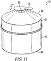
- cover 20 is conically shaped, as seen in FIG. 3 and 11 .
- Cover 20 may also include the shape of a frustrated cone as seen in FIGS. 1 , 7 and 8 .
- Cover 20 also includes a cover side wall 21 extending down from the angled portion of the cover in some embodiments as seen in FIG. 11 .
- Cover 20 may also be completely detachable from container 11, as seen in FIG. 3 in some embodiments. As such, once carrier 14 is installed in container 11, cover 20 is then positioned on the container 11.
- cover 20 is pivotally attached to container 11 at a cover hinge 15, seen in FIG. 7 .
- Cover 20 maybe pivoted away from container 11 for accessing carrier 14 and pivoted back toward container 11 for closing the top opening of container 11.
- a cover flange 17 may also be disposed on cover 20 in some embodiments. Cover flange 17 protrudes downwardly from a portion of the lower perimeter of cover 20 in some embodiments. Cover flange 17 may provide a place for a user to engage cover 20 to rotate cover 20 away from container 11.
- a cover handle 66 is positioned on cover 20 as seen in FIG. 15 .
- a user may use a cooking utensil to engage cover handle 66 and lift cover 20 from container 11. When cover 20 is closed against container 11, it may be difficult to get a utensil into the small gap between the upper edge of container 11 and the lower edge of cover 20.
- Cover flange 17 protrudes downwardly beyond the intersection of cover 20 and container 11 when cover 20 is in the closed position.
- a user may use a utensil to engage the lower edge of cover flange 17 along the side of container 11 to manually lift the cover 20 away from container 11.
- cover 20 includes one or more cover vents 22 defined in the upper portion of cover 20.
- Each cover vent 22 allows smoke to be released from smoker apparatus 10 and to allow air flow through the device.
- cover vent 22 includes an adjustable opening size using one or more sliding cover vent tabs. Each cover vent tab may be rotated about a pivot point on cover 20 to selectively open or close cover vent 22. When cover vent 22 is fully open, greater air flow may be achieved through smoker apparatus 10, and more smoke may be produced. When cover vent 22 is in a more closed position, air flow may be restricted and less smoke may be produced.
- a user may set smoker apparatus 10 to produce just the right amount of smoke for a desired application.
- cover vent 22 is illustrated.
- the cover vent opening size is adjustable.
- a vent cover plate 25 with one or more vent openings is movably attached to the surface of the cover 20 such that the movement of the vent cover plate aligns the vent cover plate opening with all or part of a cover vent 22.
- the vent cover plate is a solid plate connected movably to the cover 20 surface such that the movement of the vent cover plate covers all, part or none of the cover vent 22.
- a handle 66 is disposed on smoker apparatus 10.
- Handle 66 may be attached to cover 20 in some embodiments. As such, a user may manually engage handle 66 to lift cover 20 from the container 11.
- handle 66 may be attached to container 11 such that the smoker apparatus 10 as a whole may be moved using handle 66.
- container 11 may include handle 66 and cover 20 may include a separate handle 66.
- an integrated cover handle 27 protrudes upwardly from cover 20.
- Integrated cover handle 27 includes a portion of cover 20 having a substantially uniform diameter such that a user may use a pair of tongs or pliers to grasp integrated cover handle 27 and lift cover 20 from container 11.
- Integrated cover handle 27 may also include a cover vent 22 defined therein, as seen in FIG. 2 , in some embodiments.
- container 11 includes a base 40.
- Base 40 provides an ash collection function in some embodiments.
- Base 40 forms a bottom to container 11 in some embodiments, as seen in FIGS. 11-17 .
- the ash has a tendency to fall downwardly due to gravity.
- base 40 includes a plate or dish having a larger outer dimension than container 11.
- Base 40 also includes an angled base ramp 68, seen in FIGS. 2 , 4 , 8 and 9 .
- Ash falling from carrier 14 collects on base ramp 68 and slides down base ramp to a collection area 70 on base 40.
- Collection area 70 may include an outer upturned boundary wall in some embodiments, as seen in FIGS. 2 and 4 . Ash falling from carrier 14 thus may be collected on base 40, and when the smoking procedure is complete, the ash may be dumped from the base 40 into an appropriate trash area.
- base 40 is modified to include an outer base wall 46, seen in FIG. 9 and FIGS. 1 , 7 , 8 and 9 .
- Outer base wall 46 provides a cover for ash deposited in collection area 70.
- outer base wall 46 rises upwardly at an angle and forms an outer base wall opening 72, seen in FIG. 9 and FIG. 10 .
- Container 11 is generally dimensioned to fit inside outer base wall opening 72 in some embodiments.
- outer base wall opening 72 includes an outer base wall opening diameter 74
- container 11 includes an outer diameter.
- outer base wall opening diameter 74 is substantially equal to or slightly larger than the container diameter at the lower portion of container 11 inserted into the base 40. This results in a tight fit between the inner upper edge of outer base wall 46 and the outer perimeter of container 11. This tight fit is desirable in many applications to prevent ash material from escaping from collection area 70.
- collection area 70 is defined between outer base wall 46 and inner base wall 48, as seen in FIG. 10 . It is noted that in some embodiments inner base wall 48 defines an inner base wall height 52, and outer base wall 46 defines an outer base wall height 54.
- inner base wall height 52 is greater than outer base wall height 54. As such, the center section of base 40 adjacent base vent 42 protrudes slightly upwardly from the outer base wall opening 72. Additionally, in some embodiments, base vent 42 defines a base vent diameter 44 smaller than outer base wall opening diameter 74.
- inner base wall 48 forming base ramp 68 includes a lower surface having the shape of an inverted funnel.
- the lower side of base ramp 68 formed by inner base wall 48 being angled upwardly at a lower base wall angle 50 provides an additional concentration of heat rising upwardly from the bottom of base 40. As heat rises upwardly toward the underside of base ramp 68, the heat is concentrated toward base vent 42. This provides an additional advantage over conventional smokers for increasing the heat applied to the smoke producing material directly above base vent 42 in some embodiments.
- carrier 14 includes a height above base 40 greater than the height of container 11 above 40, forming an offset height H of carrier 14 greater than container 11.
- carrier 14 includes a portion that extends above the upper edge 11a of container 11.
- ASTM A424 Type 1 steel is used as the heat resistant material for some or all of the various components of the smoker apparatus 10 and/or heat concentrator 30.
- Other possible heat resistant materials could include stainless steel or porcelain enamel coated metals.
- smoker apparatus 10 is configured to be used on side burner 110 outside of a grill enclosure 102.
- Smoker apparatus 10 includes a vent extension 100 coupled to cover vent 20.
- the vent extension 100 is shaped to extend from the smoker apparatus 10 to an enclosure opening 104 in the grill enclosure 102.
- the vent extension 100 can include a hollow tube or conduit in some embodiments.
- Vent extension 100 can include a flexible or rigid pipe in some embodiments.
- an integrated grill smoker apparatus 200 in some embodiments, which are not according to the present invention, includes a container body 204 with a cover 205 and a base 207.
- the container, cover and base can be formed in a disposable arrangement such as a three-piece can arrangement in some embodiments.
- a removable cap 202 is located on cover 205 over the cover vent.
- the removable cap 202 may be unscrewed and removed by a user to open the cover vent.
- the removable cap 202 may include a plastic cap threaded onto the cover in some embodiments.
- the container 204 is pre-filled with smoke producing materials such as wood chips or pellets in some applications.
- a seal or other removable cap is located on base 207 covering the base vent.
- a user may remove the removable cap covering the base vent prior to use to allow air to enter the base vent.
- one or more grooves or ridges 206a, 206b, 206c may be formed in the container body. Each groove or ridge provides a contoured profile to the container body in a corrugated arrangement. Each groove 206 defines a local air channel 212a, 212b, 212c, etc. on the interior of the container 204, as seen in FIG. 20 . Each air channel provides a passage for air to travel upwardly through the container and engage the smoke producing material 214 housed in the container.
Landscapes
- Life Sciences & Earth Sciences (AREA)
- Engineering & Computer Science (AREA)
- Wood Science & Technology (AREA)
- Zoology (AREA)
- Chemical & Material Sciences (AREA)
- Food Science & Technology (AREA)
- Polymers & Plastics (AREA)
- Baking, Grill, Roasting (AREA)
Description
- The present disclosure relates generally to an apparatus for smoking food and more particularly to an apparatus that provides a smoking apparatus for positioning inside a cooking enclosure such as a grill or smoker for smoking food.
- Devices for smoking food are generally known in the art. Some food smoking devices include self-contained enclosures in which the food to be smoked is placed. The enclosures can be closed and sealed to contain smoke that imparts flavor to the food, usually with a lid. Inside the enclosure, there is a support structure, such as a grid or platform, on which the meat or other food is placed. Smoke producing material such as charcoal or wood is also placed in the enclosure and ignited. The smoke producing materials are often wood chips soaked in water to facilitate the creation of the smoke, wood pellets designed to burn or smolder when a heat source is applied to the pellets, or liquids that render a flavored smoke when heated. Conventional smokers of this nature are generally large enclosures having a generally cylindrical shape. Most conventional smokers of this nature also rely on burning material for heat and smoke production, as opposed to combustion of flammable gas such as propane.
- One problem associated with conventional food-smoking devices is the large, cumbersome hardware associated with a stand-alone smoker. Many consumers own a conventional gas or charcoal-fired grill. Such consumers often do not want to purchase an additional enclosure for smoking food. Additionally, many consumers do not have the additional space for an additional enclosure such as stand-alone smoker on their patios or decks.
- Others have attempted to overcome the problems of conventional stand-alone smokers by providing smoke producing devices and materials that may be used with a conventional gas or charcoal-fired grill to smoke food. For example, wood chips may be placed directly over a heat source in a conventional gas or charcoal-fired grill. During use, the wood chips can be ignited and can burn slowly during cooking to produce smoke. However, this conventional method of producing smoke has many drawbacks. It is often difficult to produce a desired amount of smoke, or to control smoke production, using this crude method. Some existing devices are represented by the following references.
U.S. Patent No. 5,176,124 ,U.S. Patent No. 5,359,988 ,U.S. Patent No. 5,218,950 ,U.S. Patent No. 119,169 ,U.S. Patent No. 6,103,291 ,US2012/107476 ,US20047200359 , andU.S. Patent No. 5,768,983 all disclose certain embodiments of various food grills, food smokers, or other devices. - Still others have developed containers for holding smoke producing chips for placing on a grilling surface such as a grid, grate or platform, or directly on gas burners or charcoal. These types of containers include open trays or covered pans that may be vented to permit smoke from the heated smoke producing material to escape. The food is placed on the cooking surface of the grill, and the smoke is contained by closing the cover on the grill, which may or may not allow for the regulation of the amount of smoke within the enclosed cooking area by adjustable vents in the grill cover. These devices also have problems and generally do not produce a desirable amount of smoke for smoking food.
- The smoked flavor imparted to the food is dependent upon the nature and amount of smoke to which the food is exposed, as well as the duration of exposure to the smoke during cooking. The more smoke produced by the smoking device, the faster the smoke flavor is imparted to the food. Consequently, more smoke flavor can be imparted to the food in less cooking time when the smoking device produces more smoke under any given cooking conditions. With more smoke, a piece of food that is cooked more rapidly at a higher temperature can be infused with as much smoke flavor as a similar piece of food cooked for a longer period of time at a lower cooking temperature. Also, with more smoke, a piece of food that is cooked to a lesser degree of doneness (e.g., rare) can have the same degree of smoky flavor imparted to it as a similar piece of food cooked at the same temperature for a longer period of time to a greater degree of doneness (e.g., well done).
- In conventional smoker devices, the amount of smoke generated by the smoke producing material is dependent upon several factors, including the composition of the smoke producing material, the amount and nature of the heat applied to the smoke producing material, either directly or indirectly, and the air flow around the heated smoke producing material.
- Many existing smoking devices that can be used with conventional barbecue grills are placed on top of the open grill, which serves solely as the heat source for the device but does not permit the use of the grill's cooking surface because the device is otherwise a closed system in which the meat is placed within the device along with the source of the smoke. The cooking capacity of those types of devices is, therefore, limited to something less than that of the grill. Because much of the heat generated by the grill is dissipated to the outside of the smoking device, these types of grill-top smokers consume more energy to produce the heat necessary to cook the meat and to cause the smoke producing material to smoke, and their lesser energy efficiency makes them more expensive to operate.
- Other smoking devices that are designed to be used with a conventional barbecue grill under a closed cover may allow the end-user to use the grill's cooking surface, but do not optimize the amount of smoke produced by the smoke producing material either because the source of heat used to heat the smoke producing material is diffuse and less efficient at heating the smoke producing material or because the arrangement of the smoke producing material does not optimize the production of smoke by the heated smoke producing material. Still other existing smoking devices used with conventional grills are limited with respect to the smoke producing material that may be used. In many existing devices, the heat is directed to the smoke producing material from only a single direction and/or the air flow about the heated smoke producing material is limited thus limiting the smoke producing materials' exposure to the heat, heating the smoke producing material unevenly or incompletely, and/or limiting the amount of smoke produced by the smoke producing material.
- Other conventional smoking devices include external smokers that are attached to the outside of a conventional grill and inject smoke into the grill enclosure. Such conventional devices typically require a modification of the grill enclosure, such as drilling holes into or connecting tubing to the grill for allowing passage of smoke from the external device to the interior of the grill enclosure. This type of installation is burdensome on users of conventional grills. Additionally, many conventional grill users do not like the idea of drilling holes in their expensive grills. Another problem associated with conventional external smoking devices is exposure to the weather. By placing a smoker device on the exterior of a grill, rain, wind and snow can damage and cause corrosion in the smoker. Additionally, insects and animals may form nests in such external smoker devices.
- Another problem with conventional smoker devices that are rigidly affixed to a grill is that the smoker device becomes immoveable upon installation. For example, some conventional smoker devices require a user to permanently bolt or attach the smoker to the exterior or interior of a grill. This is an inconvenience for the user in the event the user desires to use the smoker apparatus on a different grill or transport the smoker apparatus independently of the grill to which it is attached.
- What is needed, then, are improved smoking devices that operate with a conventional grill, allowing the grill to be used both as a cooking device and a smoker. Also needed are improved smoker devices that are configured to be placed and operated on the interior of a grill enclosure.
- The present disclosure provides a grill smoker apparatus for smoking food inside the enclosure of a conventional grill as defined in the appended set of claims. The smoker apparatus includes a heat resistant container having one or more side walls, an open upper end defined by the perimeter of the one or more side walls, and an opening in the lower end. The apparatus also includes a heat resistant carrier having one or more side walls, an open upper end and a bottom, with the one or more side walls and bottom having perforations, and the carrier having dimensions such that the carrier fits within the container.
- In some embodiments, the grill smoker apparatus also includes a cover with one or more cover vent holes. The cover fits against the upper end of the container in a close engagement when the carrier is positioned within the container.
- The grill smoker apparatus includes a base at the lower end of the container. The base includes a base vent shaped to allow air to pass through the base into the container. The base vent is located on an inverted base ramp defined in the base extending toward the interior of the container in some embodiments.
- A heat concentrator is positioned in the grill enclosure below the base. The heat concentrator includes a lower opening and an upper opening, the lower opening being larger than the upper opening. The heat concentrator forms an inverted funnel shape and provides a local flame or heat jet below the base vent for lighting smoke producing items retained in the carrier.
- One object of the present disclosure is to provide a grill smoker apparatus for use inside the enclosure of a grill. The grill smoker apparatus is configured to produce smoke inside the grill to smoke food during cooking or as a standalone smoking device using the grill enclosures.
- A further object of the present disclosure is to provide a grill smoker apparatus having a removable carrier for retaining smoke producing products such as wood chips or pellets.
- Another object of the present disclosure is to provide an air gap between the carrier and the container to provide improved air flow to the smoke producing material retained in the carrier.
- Yet another object of the present disclosure in some embodiments is to provide a single-use grill smoker apparatus having a container, cover and base with smoke producing material housed in the container. One or more air channels are defined in the container to allow air flow to the smoke producing material. The base includes a base vent, and the cover includes a cover vent to allow air flow through the device. The air channels may be formed via integral longitudinal channels or grooves formed in the container.
- Another object of the present disclosure is to provide a grill smoker apparatus having a container with an integral base formed together as a one-piece unit, a base vent in the base, and a cover having a cover vent disposed on the container. A carrier is positioned in the container, and an air gap is defined between the carrier and the container.
- A further object of the present disclosure is to provide a grill smoker apparatus having a container and a separate base, wherein the container fits onto the base, the base having a base vent.
- Numerous other objects, features and advantages of the present invention will be readily apparent to those of skill in the art, upon a reading of the following disclosure, when taken in conjunction with the accompanying drawings.
-
-
FIG. 1 illustrates a perspective view of an embodiment of a grill smoker apparatus in accordance with the present disclosure. -
FIG. 2 illustrates a perspective view of an alternative embodiment of a grill smoker apparatus in accordance with the present disclosure. -
FIG. 3 illustrates an exploded perspective view of an embodiment of a grill smoker apparatus in accordance with the present disclosure. -
FIG. 4 illustrates a partial cross-sectional view of an embodiment of a grill smoker apparatus in accordance with the present disclosure. -
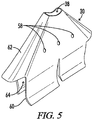
FIG. 5 illustrates a perspective view of an embodiment of a heat concentrator for a grill smoker apparatus in accordance with the present disclosure. -
FIG. 6 illustrates a lower perspective view of an embodiment of a grill smoker apparatus in accordance with the present disclosure. -
FIG. 7 illustrates a perspective view of an embodiment of a grill smoker apparatus with a hinged cover in accordance with the present disclosure. -
FIG. 8 illustrates a cross-sectional view of an embodiment of a grill smoker apparatus in accordance with the present disclosure. -
FIG. 9 illustrates an embodiment of a base for a grill smoker apparatus in accordance with the present disclosure. -
FIG. 10 illustrates a cross-sectional view of Section 10-10 ofFIG. 9 in accordance with the present disclosure. -
FIG. 11 illustrates a perspective view of an embodiment of a grill smoker apparatus in accordance with the present disclosure. -
FIG. 12 illustrates a perspective bottom view of the embodiment of a grill smoker apparatus ofFIG. 11 . -
FIG. 13 illustrates a partially exploded view of an embodiment of a grill smoker apparatus with a cover removed from the container. -
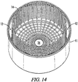
FIG. 14 illustrates a top perspective view of an embodiment of a grill smoker apparatus including a container with carrier viewed from above with the cover removed. -
FIG. 15 illustrates a cross-sectional view of an embodiment of a grill smoker apparatus. -
FIG. 16 illustrates a perspective cross-sectional view of an embodiment of a grill smoker apparatus with a carrier having an ash blocker. -
FIG. 17 illustrates a bottom perspective cross-sectional view of an embodiment of a smoker apparatus with a carrier having an ash blocker. -
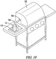
FIG. 18 illustrates a perspective view of a grill with a grill smoker apparatus (which is not according to the present invention) positioned on a side burner outside the grill enclosure. -
FIG. 19 illustrates a perspective view of an alternative embodiment of a grill smoker apparatus, which is not according to the present invention. -
FIG. 20 illustrates a partial cross-sectional view of Section 20-20 ofFIG. 19 . - Throughout the specification and claims, the following terms take at least the meanings explicitly associated herein, unless the context dictates otherwise. The meanings identified below do not necessarily limit the terms, but merely provide illustrative examples for the terms. The meaning of "a," "an," and "the" may include plural references, and the meaning of "in" may include "in" and "on." The phrase "is an embodiment" as used herein does not necessarily refer to the same embodiment, although it may. It is understood that in the drawings not all reference numbers are included in each drawing, for the sake of clarity. In addition, positional terms such as "upper," "lower," "side," "top," "bottom," "inner," "outer," "vertical," "horizontal," etc. refer to the apparatus when in the orientation shown in the drawing. The skilled artisan will recognize that objects in accordance with the present disclosure can assume different orientations when in use.
- Included herein are multiple illustrations of various embodiments of food smoking devices in accordance the present disclosure. Briefly stated, a grill smoker apparatus in accordance with the various embodiments of the present disclosure provides a user with a way to smoke meat and other foods in a conventional grill enclosure such as on a gas or charcoal grill. The smoker apparatus provides an improvement over conventional devices in some embodiments in that the grill smoker apparatus is configured to be placed inside the grill enclosure during the smoking and/or cooking procedures.
- Referring now to the drawings, an embodiment of a
smoker apparatus 10 is illustrated inFIG. 1 . Alternative embodiments of grill smoker devices are shown inFIGS. 11-20 .Smoker apparatus 10 includes abase 40 and acontainer 11 positioned onbase 40.Base 40 is integrated oncontainer 11 as a one-piece unit in some embodiments, such as being formed from a single piece of metal or welded together to form an integral unit. In other embodiments,base 40 is a separate piece fromcontainer 11.Container 11 includes a hollow interior configured for containing a smoke producing material such as wood chips, pellets, wood shavings, smoke fuel, or any other suitable smoke producing material known in the art.Base 40 is generally configured to be placed directly onto a grill cooking surface such as a cooking grid orgrilling platform 28, seen inFIGS. 2 and4 . In some embodiments,base 40 sits directly on grillingplatform 28 inside the grill enclosure during smoking procedures. - Referring to
FIGS. 1-3 ,13 and15-17 ,smoker apparatus 10 in some embodiments includes acontainer 11, afuel carrier 14 that fits withincontainer 11, and a ventedcover 20 that fits on the upper end of thecontainer 11.Carrier 14 is generally configured to contain smoke producing materials such as wood chips or wood pellets.Carrier 14 can include any suitable heat-resistant material such as metal, ceramic, porcelain, etc. in various embodiments.Container 11 includes an inner dimension, or inner diameter, such thatcarrier 14 may be inserted into the interior ofcontainer 11, as seen inFIG. 4 .Carrier 14 defines an outer carrier dimension, or outer diameter, smaller than the inner diameter ofcontainer 11. In some embodiments,carrier 14 includes a wire mesh basket or bowl dimensioned to fit insidecontainer 11.Carrier 14 in alternative embodiments can include a wire mesh screen or any suitable material for housing smoke producing materials. - One aspect of the present disclosure provides enhanced airflow to the smoke producing material housed in
carrier 14. Referring further toFIG. 3 andFIG. 4 ,carrier 14 includes a plurality of carrier holes 16 defined in the carrier walls and carrier bottom. Carrier holes 16 allow air to enter intocarrier 14 not only from below but also from the sides to promote burning or heating of the smoke producing materials housed incarrier 14. Smoke producing materials stored incarrier 14 may produce smoke in relation to the amount of air available for combustion of the material. By allowing more air to enter into thecarrier 14, more smoke may be produced. Thus, carrier holes 16 operate to improve the capacity ofsmoker apparatus 10 to produce a sufficient amount of smoke. - Referring further to
FIGS. 4 and14-15 ,carrier 14 includes an outer dimension smaller than the inner dimension ofcontainer 11 such that acarrier gap 12 is defined between the interior surface ofcontainer 11 and the outer dimension ofcarrier 14.Carrier gap 12 operates as a plenum for allowing passage of air betweencarrier 14 and the interior walls ofcontainer 11. By allowing air to travel upwardly into thecarrier gap 12 partially or fully surroundingcarrier 14, enhanced air flow intocarrier 14 via carrier holes 16 may be achieved. Thus, improved smoke production is possible as described above.Carrier gap 12 defines acarrier gap width 13, seen inFIGS. 8 and15 , defined as the radial distance locally between the outer dimension ofcarrier 14 and the inner surface wall ofcontainer 11.Carrier gap width 13 may be uniform around the perimeter ofcarrier 14 in some embodiments. In alternative embodiments,carrier gap width 13 may vary along the perimeter ofcarrier 14. - Referring further to
FIG. 2 , in some embodiments,container 11 defines a plurality ofcontainer legs 26 protruding downwardly from the lower edge ofcontainer 11. Eachcontainer leg 26 provides a support forcontainer 11. Eachcontainer leg 26 may rest against a base 40 or alternatively may be configured to engage a grilling platform directly. Acontainer vent 24 is defined between eachadjacent container leg 26. Eachcontainer vent 24 allows air to enter into thecarrier gap 12 betweencarrier 14 andcontainer 11. As such, enhanced air flow into thecarrier gap 12 and through carrier holes 16 to the smoke producing material housed incarrier 14 may be achieved viacontainer vent 24. - Referring further to
FIGS. 3 and14-15 , in some embodiments, acarrier vent 36 is defined at the bottom ofcarrier 14.Carrier vent 36 includes a hole defined in the bottom ofcarrier 14.Carrier vent 36 allows the passage of air intocarrier 14 from the bottom. In other embodiments,carrier vent 36 may be absent. In such embodiments where carrier vent 36 is absent, the bottom ofcarrier 14 may include carrier holes 16. Furthermore, the bottom ofcarrier 14 may include anash blocker 37 rather than carrier vent 36 so as to completely or partially block the falling of ash or remnants of the smoke producing material onto the heat source, as seen inFIGS. 16 and17 . Additionally, in some embodiments,smoker apparatus 10 is configured to allow ignition of the smoke producing material inside thecarrier 14 by a heat source inside the grilling enclosure. As such, heat may be supplied to the smoke producing material into thecarrier 14 from below thesmoker apparatus 10 via thecarrier vent 36. For example, whensmoker apparatus 10 is positioned on a grilling surface inside a conventional grilling enclosure, the charcoal or gas burner directly below thesmoker apparatus 10 may be used in some embodiments to ignite or heat the smoke producing material stored incarrier 14.Carrier 14 is positioned an offsetheight 35 above the base vent in some embodiments. - In some applications, it is necessary to provide an open flame to the smoke producing material stored in
carrier 14 to ignite or heat the material. As such, it may be necessary to provide a flame upwardly through thecarrier vent 36 to ignite or heat the smoke producing material. Conventional grilling devices such as conventional gas grills or charcoal grills may not provide sufficient localized heat to initiate an ignition of the smoke producing material from below. Others have resorted to using lighter fluid and/or an external ignition device such as a grill lighter to initiate combustion of the smoke producing material inside the container. - To accommodate direct ignition of the smoke producing material without resorting to external ignition devices, the present disclosure provides a
heat concentrator 30 as seen inFIGS. 1 ,4 and5 to be positioned directly below thesmoker apparatus 10.Heat concentrator 30 is also configured to be installed inside the grilling enclosure and provides localized heat directly below thesmoker apparatus 10 to ignite or heat the smoke producing material.Heat concentrator 30 provides a chamber for concentrating heat that rises intoheat concentrator 30 from alower concentrator opening 64, seen inFIG. 5 along lower concentrator end 90.Heat concentrator 30 includes anupper concentrator opening 38 along upper concentrator end 88 having a smaller cross-sectional dimension than thelower concentrator opening 64. In some embodiments,heat concentrator 30 is installed directly onto agas burner 32, as seen inFIG. 4 .Heat concentrator 30 includes one or more concentrator supports 60 resiliently biased inwardly to provide a clamping force againstburner 32. In other embodiments,heat concentrator 30 may be suspended from grillingplatform 28 rather than supported bygas burner 32. As heated gas or flames move upwardly into thelower concentrator opening 64 and travel toward theupper concentrator opening 38, the heat or flames become compressed and further increase the temperature of the heat or flames. A slightly compressed and heated stream of air and/orflames 39 is emitted from theupper concentrator opening 38 directly into thecarrier vent 36. Where abase 40 is disposed betweencontainer 11 and the grilling platform, the compressed and heated stream of air and/orflames 39 passes through abase vent 42 defined inbase 40. In some embodiments,base vent 42 is concentrically aligned withcarrier vent 36 such that the concentrated stream of heat and/or flames may pass directly intocarrier 14 unencumbered. In other embodiments not illustrated, the concentrated stream of heat and/or flames may be directed to anash blocker 37 in the bottom ofcarrier 14. This stream of concentrated heat and/or flames may be used to ignite or heat the smoke producing material housed incarrier 14. Once the smoke producing material is ignited and the combustion process has begun, the flow of gas to heatconcentrator 30 viagas burner 32 may be reduced or eliminated to remove the concentrated heat and/or flames from thesmoker apparatus 10. -
Heat concentrator 30 includes a plurality of concentrator holes 58 defined inconcentrator wall 62 as shown inFIGS. 4 and5 . Eachconcentrator hole 58 allows air to enter the chamber defined byconcentrator wall 62. The increased airflow intoheat concentrator 30 allows for a more lean equivalence ration of fuel and air inside the heat concentrator, providing more efficient combustion and allowing higher burn temperatures for igniting the smoke producing material. -
FIGS. 1 ,4 and8 illustrate embodiments of a smoker apparatus having aheat concentrator 30 positioned belowcontainer 11. One embodiment of theheat concentrator 30 includes a chute with a plurality of side walls, as seen inFIG. 5 . Theopening 38 on the upper end of the chute has no more than one half the area of the opening on the lower end of thechute 64. At the lower end of the chute,adjustable flaps 60 that can be adjusted laterally extend downward. In some embodiments ofheat source concentrator 30, adjustable flaps are tension adjustable. In further embodiments,heat concentrator 30 many include anadjustable opening 38 for controlling heat flow. -
Carrier 14 generally must be retained incontainer 11 in some embodiments. Referring further toFIG. 6 , in some embodiments, a plurality ofcarrier support tabs carrier 14 from the outer wall ofcontainer 11. Each carrier support tab 34 is integrally formed in the wall ofcontainer 11. As such, when each carrier support tab 34 is bent inwardly, a correspondingcontainer vent 24 is created at the area where the carrier support tab material was positioned prior to being dislocated. This provides an advantage for manufacturing efficiency in some applications because container vents 24 and carrier support tabs 34 may be formed simultaneously. As seen inFIG. 6 , in some embodiments,carrier 14 rests atop the upper surface of the carrier support tabs 34. Alternatively, a variety of different supports or braces may be used to supportcarrier 14 in addition to or instead of support tabs 34. In alternative embodiments,carrier 14 may be suspended incontainer 11 via a plurality of hooks that engage the upper perimeter of thecontainer 11. In yet another embodiment,carrier 14 sits directly on the surface upon which thecontainer 11 sits, such as agrilling platform 28 orbase 40. - Referring further to
FIG. 6 , in some embodiments, a plurality ofside vents container 11. Each side vent 18 defines a hole throughcontainer 11 for providing increased air flow tocarrier gap 12. In some embodiments, as seen inFIG. 1 , side vents 18 may include anadjustable slide 19 that can be used to alter the cross-sectional opening area of the side vent 18.Slide 19 may be manually positioned to a desired location to allow a desired amount of air to enter through the side vent 18. -
Carrier 14 is situated within thecontainer 11 and connected to the inner walls of thecontainer 11 such that a carrier gap remains between the outer surfaces ofcarrier 14 and the inner surfaces of thecontainer 11. - In various embodiments,
smoker apparatus 10 may include different versions ofcover 20.Cover 20 encloses the upper end of thecontainer 11 during use. In some embodiments, cover 20 is conically shaped, as seen inFIG. 3 and11 .Cover 20 may also include the shape of a frustrated cone as seen inFIGS. 1 ,7 and8 .Cover 20 also includes acover side wall 21 extending down from the angled portion of the cover in some embodiments as seen inFIG. 11 .Cover 20 may also be completely detachable fromcontainer 11, as seen inFIG. 3 in some embodiments. As such, oncecarrier 14 is installed incontainer 11, cover 20 is then positioned on thecontainer 11. In alternative embodiments, cover 20 is pivotally attached tocontainer 11 at acover hinge 15, seen inFIG. 7 .Cover 20 maybe pivoted away fromcontainer 11 for accessingcarrier 14 and pivoted back towardcontainer 11 for closing the top opening ofcontainer 11. Acover flange 17 may also be disposed oncover 20 in some embodiments.Cover flange 17 protrudes downwardly from a portion of the lower perimeter ofcover 20 in some embodiments.Cover flange 17 may provide a place for a user to engagecover 20 to rotatecover 20 away fromcontainer 11. Alternatively, acover handle 66 is positioned oncover 20 as seen inFIG. 15 . A user may use a cooking utensil to engage cover handle 66 and lift cover 20 fromcontainer 11. Whencover 20 is closed againstcontainer 11, it may be difficult to get a utensil into the small gap between the upper edge ofcontainer 11 and the lower edge ofcover 20.Cover flange 17 protrudes downwardly beyond the intersection ofcover 20 andcontainer 11 whencover 20 is in the closed position. A user may use a utensil to engage the lower edge ofcover flange 17 along the side ofcontainer 11 to manually lift thecover 20 away fromcontainer 11. - Referring now to
FIGS. 1 ,2 ,8 , and11 , in various embodiments, cover 20 includes one or more cover vents 22 defined in the upper portion ofcover 20. Each cover vent 22 allows smoke to be released fromsmoker apparatus 10 and to allow air flow through the device. In some embodiments, covervent 22 includes an adjustable opening size using one or more sliding cover vent tabs. Each cover vent tab may be rotated about a pivot point oncover 20 to selectively open orclose cover vent 22. When cover vent 22 is fully open, greater air flow may be achieved throughsmoker apparatus 10, and more smoke may be produced. When cover vent 22 is in a more closed position, air flow may be restricted and less smoke may be produced. By providing anadjustable cover vent 22 in various embodiments, a user may setsmoker apparatus 10 to produce just the right amount of smoke for a desired application. - Referring to the optional embodiment in
FIG. 1 , covervent 22 is illustrated. In this embodiment, the cover vent opening size is adjustable. Avent cover plate 25 with one or more vent openings is movably attached to the surface of thecover 20 such that the movement of the vent cover plate aligns the vent cover plate opening with all or part of acover vent 22. In another embodiment of a vent cover plate, as seen inFIG. 11 , the vent cover plate is a solid plate connected movably to thecover 20 surface such that the movement of the vent cover plate covers all, part or none of thecover vent 22. - Also seen in
FIG. 1 , in some embodiments, ahandle 66 is disposed onsmoker apparatus 10.Handle 66 may be attached to cover 20 in some embodiments. As such, a user may manually engagehandle 66 to liftcover 20 from thecontainer 11. Alternatively, handle 66 may be attached tocontainer 11 such that thesmoker apparatus 10 as a whole may be moved usinghandle 66. In other embodiments,container 11 may include handle 66 and cover 20 may include aseparate handle 66. - Referring further to
FIG. 3 , in some embodiments, an integrated cover handle 27 protrudes upwardly fromcover 20. Integrated cover handle 27 includes a portion ofcover 20 having a substantially uniform diameter such that a user may use a pair of tongs or pliers to grasp integrated cover handle 27 and lift cover 20 fromcontainer 11. Integrated cover handle 27 may also include acover vent 22 defined therein, as seen inFIG. 2 , in some embodiments. - Referring further to
FIGS. 2 and4 ,container 11 includes abase 40.Base 40 provides an ash collection function in some embodiments.Base 40 forms a bottom tocontainer 11 in some embodiments, as seen inFIGS. 11-17 . As the smoke producing material is burned up, ash is produced insidecarrier 14. The ash has a tendency to fall downwardly due to gravity. Whencontainer 11 is sitting directly atop the grilling platform, ash fromcarrier 14 may fall directly below thesmoker apparatus 10. That ash may circulate inside the grilling enclosure due to natural convection currents and inadvertently land on the food being cooked. This is generally undesirable. To overcome this problem in some embodiments,base 40 includes a plate or dish having a larger outer dimension thancontainer 11.Base 40 also includes anangled base ramp 68, seen inFIGS. 2 ,4 ,8 and9 . Ash falling fromcarrier 14 collects onbase ramp 68 and slides down base ramp to acollection area 70 onbase 40.Collection area 70 may include an outer upturned boundary wall in some embodiments, as seen inFIGS. 2 and4 . Ash falling fromcarrier 14 thus may be collected onbase 40, and when the smoking procedure is complete, the ash may be dumped from the base 40 into an appropriate trash area. - In some embodiments, as seen in
FIG. 2 andFIG. 4 , ash collected on the base 40 incollection area 70 may be exposed to the air currents inside the grilling enclosure. This may be a problem in some applications if the ash becomes entrained in the internal air currents and ends up making contact with the food items being smoked inside the enclosure. To overcome this problem, in some applications,base 40 is modified to include anouter base wall 46, seen inFIG. 9 andFIGS. 1 ,7 ,8 and9 .Outer base wall 46 provides a cover for ash deposited incollection area 70. For example, as seen inFIG. 7 andFIG. 9 ,outer base wall 46 rises upwardly at an angle and forms an outer base wall opening 72, seen inFIG. 9 and FIG. 10 .Container 11 is generally dimensioned to fit inside outer base wall opening 72 in some embodiments. As such, outer base wall opening 72 includes an outer basewall opening diameter 74, andcontainer 11 includes an outer diameter. In some embodiments, outer basewall opening diameter 74 is substantially equal to or slightly larger than the container diameter at the lower portion ofcontainer 11 inserted into thebase 40. This results in a tight fit between the inner upper edge ofouter base wall 46 and the outer perimeter ofcontainer 11. This tight fit is desirable in many applications to prevent ash material from escaping fromcollection area 70. In these embodiments,collection area 70 is defined betweenouter base wall 46 andinner base wall 48, as seen inFIG. 10 . It is noted that in some embodimentsinner base wall 48 defines an innerbase wall height 52, andouter base wall 46 defines an outerbase wall height 54. In some embodiments, innerbase wall height 52 is greater than outerbase wall height 54. As such, the center section ofbase 40adjacent base vent 42 protrudes slightly upwardly from the outerbase wall opening 72. Additionally, in some embodiments,base vent 42 defines abase vent diameter 44 smaller than outer basewall opening diameter 74. - Referring further to
FIGS. 9, 10 and12 , in some embodiments,inner base wall 48 formingbase ramp 68 includes a lower surface having the shape of an inverted funnel. The lower side ofbase ramp 68 formed byinner base wall 48 being angled upwardly at a lowerbase wall angle 50 provides an additional concentration of heat rising upwardly from the bottom ofbase 40. As heat rises upwardly toward the underside ofbase ramp 68, the heat is concentrated towardbase vent 42. This provides an additional advantage over conventional smokers for increasing the heat applied to the smoke producing material directly abovebase vent 42 in some embodiments. - As seen in
FIG. 13 , in some embodiments,carrier 14 includes a height abovebase 40 greater than the height ofcontainer 11 above 40, forming an offset height H ofcarrier 14 greater thancontainer 11. As such,carrier 14 includes a portion that extends above theupper edge 11a ofcontainer 11. Whencover 20 is placed oncontainer 11, an engagement is formed between thelower edge 20a ofcover side wall 21 and theupper edge 11a ofcontainer 11. It is advantageous in some applications to have the intersection of cover and container at a position lower on the device to distance the intersection from thecover vent 22 to reduce the likelihood of smoke escaping from the intersection instead of thecover vent 22. - Different material compositions may be used to form the various structural features of
smoker apparatus 10 orheat concentrator 30. In some embodiments, ASTM A424 Type 1 steel is used as the heat resistant material for some or all of the various components of thesmoker apparatus 10 and/orheat concentrator 30. Other possible heat resistant materials could include stainless steel or porcelain enamel coated metals. - Referring further to
FIG. 18 , in some embodiments, which are not according to the present invention,smoker apparatus 10 is configured to be used onside burner 110 outside of agrill enclosure 102.Smoker apparatus 10 includes avent extension 100 coupled to covervent 20. Thevent extension 100 is shaped to extend from thesmoker apparatus 10 to anenclosure opening 104 in thegrill enclosure 102. Thevent extension 100 can include a hollow tube or conduit in some embodiments.Vent extension 100 can include a flexible or rigid pipe in some embodiments. - Referring further to
FIGS. 19-20 , an integratedgrill smoker apparatus 200 in some embodiments, which are not according to the present invention, includes acontainer body 204 with acover 205 and abase 207. The container, cover and base can be formed in a disposable arrangement such as a three-piece can arrangement in some embodiments. Aremovable cap 202 is located oncover 205 over the cover vent. Theremovable cap 202 may be unscrewed and removed by a user to open the cover vent. Theremovable cap 202 may include a plastic cap threaded onto the cover in some embodiments. Thecontainer 204 is pre-filled with smoke producing materials such as wood chips or pellets in some applications. A seal or other removable cap is located onbase 207 covering the base vent. A user may remove the removable cap covering the base vent prior to use to allow air to enter the base vent. Additionally, one or more grooves orridges groove 206 defines alocal air channel container 204, as seen inFIG. 20 . Each air channel provides a passage for air to travel upwardly through the container and engage thesmoke producing material 214 housed in the container. - Furthermore, sizes of various structural parts and materials used to make the above mentioned components are illustrative and exemplary only, and persons of ordinary skill in the art would recognize that these sizes and materials can be changed as necessary to produce different results or different desired characteristics or capabilities. It should be understood that the
smoker apparatus 10 and/orheat concentrator 30 are not limited to the examples disclosed in the specification. - Thus, although there have been described particular embodiments of a new and useful grill smoker apparatus and heat concentrator it is not intended that such references be construed as limitations upon the scope of the present invention except as set forth in the following Claims.
Claims (12)
- A grill smoker apparatus (10), comprising:a container (11);a cover (20) disposed on the container (11);a carrier (14) disposed in the container (11), the carrier (14) including a plurality of carrier holes (16) for allowing air passage into the carrier (14);a carrier gap (12) defined between the container (11) and the carrier (14), the carrier gap (12) configured to allow air to flow between the container (11) and the carrier (14);a base (40) positioned at a lower end of the container (11), the base (40) including a base ramp (68) inclined inwardly toward the carrier (14), and a base vent (42) defined on the base ramp (68), the base vent (42) open to an interior of the container (11), the carrier (14) positioned above the base vent (42);a heat concentrator (30) positioned below the base (40) and the base vent (42), the heat concentrator (30) forming an inverted funnel shape, the heat concentrator (30) having a lower concentrator opening (64) and an upper concentrator opening (38), the lower concentrator opening (64) being larger than the upper concentrator opening (38), the upper concentrator opening (38) aligned below the base vent (42);a plurality of concentrator holes (58) defined in a concentrator wall (62) of the heat concentrator (30); andone or more concentrator supports (60) included on the heat concentrator (30), the one or more concentrator supports (60) resiliently biased inwardly.
- The apparatus (10) of claim 1, further comprising the carrier (14) having an outer perimeter, and the carrier gap (12) forming a continuous annular gap around the outer perimeter of the carrier (14).
- The apparatus (10) of claim 1, wherein the carrier (14) is removable from the container (11).
- The apparatus (10) of claim 1, wherein the carrier (14) comprises a wire mesh basket.
- The apparatus (10) of claim 1, wherein the cover (20) is removable from the container (11).
- The apparatus (10) of claim 1, wherein the cover (20) is pivotally attached to the container (11) at a hinge (15).
- The apparatus (10) of claim 1, wherein the base ramp (68) has the shape of an inverted funnel.
- The apparatus (10) of claim 1, further comprising a carrier vent (36) defined in the carrier opposite the base vent (42).
- The apparatus (10) of claim 1, further comprising an ash blocker (37) on the carrier (14) opposite the base vent (42).
- The apparatus (10) of claim 1, further comprising a cover vent (22) defined in the cover (20), the cover vent (22) including a moveable vent cover plate (25).
- The apparatus (10) of claim 1, the heat concentrator (30) further comprising:one or more side walls on the concentrator wall (62) of a heat resistant material and having an upper concentrator end (88) and a lower concentrator end (90);the upper concentrator opening (38) defined at the upper end (88);the lower concentrator opening (64) defined at the lower end (90), the lower concentrator opening (64) having an opening area at least two times the opening area of the upper concentrator opening (38); andthe one or more concentrator supports (60) extending from the lower end (90) of the one or more side walls and configured to directly engage a heat source and support the heat concentrator (30) orienting the upper end (88) toward the container (11).
- The apparatus (10) of Claim 1, further comprising a carrier vent (36) defined at the bottom of the carrier (14), wherein the base vent (42) is concentrically aligned with the carrier vent (36) such that compressed and heated air passes directly into the carrier (14) from the heat concentrator (30).
Applications Claiming Priority (2)
| Application Number | Priority Date | Filing Date | Title |
|---|---|---|---|
| US201361787800P | 2013-03-15 | 2013-03-15 | |
| PCT/US2014/030069 WO2014145329A1 (en) | 2013-03-15 | 2014-03-15 | Grill smoker apparatus |
Publications (3)
| Publication Number | Publication Date |
|---|---|
| EP2967255A1 EP2967255A1 (en) | 2016-01-20 |
| EP2967255A4 EP2967255A4 (en) | 2016-12-21 |
| EP2967255B1 true EP2967255B1 (en) | 2018-08-08 |
Family
ID=51537954
Family Applications (1)
| Application Number | Title | Priority Date | Filing Date |
|---|---|---|---|
| EP14762538.8A Not-in-force EP2967255B1 (en) | 2013-03-15 | 2014-03-15 | Grill smoker apparatus |
Country Status (6)
| Country | Link |
|---|---|
| US (3) | US10420351B2 (en) |
| EP (1) | EP2967255B1 (en) |
| CN (1) | CN105263378B (en) |
| AU (1) | AU2014233183B2 (en) |
| CA (1) | CA2907341C (en) |
| WO (1) | WO2014145329A1 (en) |
Cited By (1)
| Publication number | Priority date | Publication date | Assignee | Title |
|---|---|---|---|---|
| US10876733B2 (en) | 2018-09-11 | 2020-12-29 | Spider Grills, Llc | System and method for use of pelletized fuel in a kettle grill |
Families Citing this family (39)
| Publication number | Priority date | Publication date | Assignee | Title |
|---|---|---|---|---|
| US10015975B2 (en) * | 2013-09-19 | 2018-07-10 | The Brinkmann Corporation | Smoker having internal perforated smoke stack |
| USD777516S1 (en) * | 2014-11-17 | 2017-01-31 | D. Mark Hunsaker | Fire basket for smoker |
| FR3030211B1 (en) * | 2014-12-23 | 2017-01-13 | Seb Sa | SMOKE DIFFUSION ACCESSORY FOR ELECTRIC BARBECUE |
| EP3040618B8 (en) * | 2014-12-30 | 2017-10-18 | Mimi Moto Holding B.V. | Stove with removable burning chamber |
| US10595540B1 (en) * | 2015-05-01 | 2020-03-24 | David B. Knight & Associates, Inc. | Barbecue oven having circulation control |
| AT517339B1 (en) * | 2015-07-08 | 2017-01-15 | Schneeberger Matthias | cooking apparatus |
| WO2017142900A1 (en) * | 2016-02-18 | 2017-08-24 | Spectrum Brands, Inc. | Compact smoker assembly |
| JP6793940B2 (en) * | 2016-10-21 | 2020-12-02 | 新富士バーナー株式会社 | Smoked equipment |
| US10827878B2 (en) * | 2016-10-25 | 2020-11-10 | Gmg Products, Llc. | Pizza oven accessory for barbecue grill |
| US10712010B2 (en) * | 2016-12-21 | 2020-07-14 | Firebox Outdoors Llp | Stove with multiple configurations |
| WO2018218062A1 (en) * | 2017-05-24 | 2018-11-29 | Yaghotian Ehsan Sean | Express barbeque with offset heat distributor and method of using same |
| CN110250930A (en) | 2017-08-09 | 2019-09-20 | 沙克忍者运营有限责任公司 | Cooking system |
| AU2018253579B2 (en) * | 2017-10-25 | 2019-10-10 | Valley River Mountain Pty. Ltd. | Foodstuff cooking apparatus |
| PL425080A1 (en) * | 2018-03-29 | 2019-10-07 | Nadolski Piotr P.P.H.U. Zyga | Mobile focus |
| US11035384B2 (en) * | 2018-04-25 | 2021-06-15 | Sonny's Enterprises, Llc | Silencer for an air blower assembly and air blower assembly having the silencer |
| USD914447S1 (en) | 2018-06-19 | 2021-03-30 | Sharkninja Operating Llc | Air diffuser |
| USD934027S1 (en) | 2018-08-09 | 2021-10-26 | Sharkninja Operating Llc | Reversible cooking rack |
| USD883015S1 (en) | 2018-08-09 | 2020-05-05 | Sharkninja Operating Llc | Food preparation device and parts thereof |
| USD883014S1 (en) | 2018-08-09 | 2020-05-05 | Sharkninja Operating Llc | Food preparation device |
| USD903413S1 (en) | 2018-08-09 | 2020-12-01 | Sharkninja Operating Llc | Cooking basket |
| CA3115989A1 (en) * | 2018-10-12 | 2020-04-16 | W.C. Bradley Co. | Pellet smoker |
| USD845709S1 (en) * | 2018-12-04 | 2019-04-16 | Ez Flame Bbq, Inc. | Charcoal starter platform |
| USD845708S1 (en) * | 2018-12-04 | 2019-04-16 | Ez Flame Bbq, Inc. | Charcoal starter platform |
| US11371712B2 (en) | 2019-01-25 | 2022-06-28 | Weber-Stephen Products Llc | Pellet grills |
| WO2020176477A1 (en) | 2019-02-25 | 2020-09-03 | Sharkninja Operating Llc | Cooking system with guard |
| US11033146B2 (en) | 2019-02-25 | 2021-06-15 | Sharkninja Operating Llc | Cooking device and components thereof |
| US20200305450A1 (en) * | 2019-03-28 | 2020-10-01 | Hall Of Fame Innovations Llc | Rapid, portable food smoking device |
| USD918654S1 (en) | 2019-06-06 | 2021-05-11 | Sharkninja Operating Llc | Grill plate |
| USD982375S1 (en) | 2019-06-06 | 2023-04-04 | Sharkninja Operating Llc | Food preparation device |
| US11759051B2 (en) | 2019-11-11 | 2023-09-19 | Turbo Trusser Llc | Smoking and basting lid |
| US11659843B2 (en) * | 2019-11-12 | 2023-05-30 | Fabrice Marcy Andre-Bartley | Food smoking skewer |
| US11678765B2 (en) | 2020-03-30 | 2023-06-20 | Sharkninja Operating Llc | Cooking device and components thereof |
| USD967670S1 (en) | 2020-04-29 | 2022-10-25 | Hall Of Fame Innovations Llc | Lid for smoking and basting |
| US12089780B2 (en) * | 2020-10-12 | 2024-09-17 | Michael Konrath | Universal and removable diffuser for a grill |
| US11744256B2 (en) | 2020-11-20 | 2023-09-05 | Soak Limited | Device and method for imparting smoked flavors to beverages and foodstuffs |
| USD944594S1 (en) | 2020-11-20 | 2022-03-01 | Soak Limited | Smoker device |
| US12078358B2 (en) * | 2022-01-12 | 2024-09-03 | Jordan Kahn Company | Fire pit |
| US20230309745A1 (en) * | 2022-03-29 | 2023-10-05 | Sharkninja Operating Llc | Grill system with smoke assembly |
| US20240196914A1 (en) * | 2022-12-19 | 2024-06-20 | W.C. Bradley Co. | Cold Smoke System |
Family Cites Families (147)
| Publication number | Priority date | Publication date | Assignee | Title |
|---|---|---|---|---|
| USRE16011E (en) * | 1925-03-03 | Poration | ||
| US161577A (en) * | 1875-03-30 | Improvement in coal-hods | ||
| US103736A (en) * | 1870-05-31 | Seth gregoey | ||
| US119169A (en) * | 1871-09-19 | Improvement in culinary-steamers | ||
| US1038420A (en) * | 1912-05-21 | 1912-09-10 | Nathan B Newcomer | Orchard-heater. |
| US1919407A (en) | 1929-12-03 | 1933-07-25 | Fred W Pope | Vegetable and orchard heater |
| US2611311A (en) | 1946-12-06 | 1952-09-23 | Herbert G Irwin | Smoke absorbent smoker |
| US2641085A (en) * | 1950-09-21 | 1953-06-09 | Robinson | Heater for fields, orchards, and the like |
| US2997566A (en) | 1959-04-14 | 1961-08-22 | Raytheon Co | Microwave apparatus |
| US3073263A (en) * | 1960-12-27 | 1963-01-15 | Francis Y Wynkoop | Charcoal igniter and stove |
| US3307506A (en) | 1963-03-08 | 1967-03-07 | Jack E Rose | Fire starting device |
| US3413935A (en) * | 1966-03-28 | 1968-12-03 | Burton E Adams | Container for igniting charcoal and the like |
| US3453975A (en) | 1967-10-20 | 1969-07-08 | Dalton D Gunter | Charcoal starter |
| US3586518A (en) * | 1969-04-01 | 1971-06-22 | Earl T Folmar | Electric barbecue machine |
| US3739732A (en) | 1971-05-24 | 1973-06-19 | T Graham | Portable charcoal igniter |
| US3838249A (en) | 1972-04-21 | 1974-09-24 | Siemens Elektrogeraete Gmbh | Cooking tray |
| US3765397A (en) * | 1973-03-07 | 1973-10-16 | R Henderson | Portable charcoal stove |
| US3903866A (en) | 1973-07-18 | 1975-09-09 | Stevens Supply Company | Charcoal lighter device |
| US3934520A (en) | 1974-10-10 | 1976-01-27 | K & B Industries, Inc. | Charcoal starter |
| US4020322A (en) | 1976-05-14 | 1977-04-26 | Muse Edward T | Multi smoker |
| US4094295A (en) * | 1976-06-28 | 1978-06-13 | Bosman Industries, Inc. | Charcoal and water smoker and cooker |
| US4094649A (en) * | 1977-02-28 | 1978-06-13 | Osterried Gordon A | Briquette igniting device with foraminous metal cone |
| US4413609A (en) * | 1978-02-15 | 1983-11-08 | Tisdale Reynold D | Portable Hibachi-type charcoal grill with kindling structure |
| US4227510A (en) | 1978-05-30 | 1980-10-14 | Frazier Robert D | Charcoal briquet lighter |
| US4334462A (en) * | 1980-11-13 | 1982-06-15 | The Coleman Company, Inc. | Gas-fired cooking apparatus |
| USD270987S (en) * | 1981-03-09 | 1983-10-18 | Scheufler John H | Barbecue |
| US4374489A (en) * | 1981-06-15 | 1983-02-22 | Ole-Arkie Corp. | Adaptable food smoker attachment |
| US4417565A (en) * | 1982-05-10 | 1983-11-29 | Walter Karpinia | Fast and easy charcoal starter |
| US4401017A (en) | 1982-07-14 | 1983-08-30 | Trend Products Company | Steamer pot assembly |
| DE3317624A1 (en) | 1982-08-13 | 1984-11-15 | Fischer, Karl, 7519 Oberderdingen | Arrangement for building-in an electric cooking plate |
| US4508094A (en) * | 1982-11-12 | 1985-04-02 | Pyromid, Inc. | Convertible cooking unit |
| US4531505A (en) * | 1983-06-09 | 1985-07-30 | Pyromid, Inc. | Convertible cooking unit with an oven |
| US4509412B1 (en) | 1983-03-04 | 1994-01-11 | Rival Manufacturing Company | Food steaming device |
| US4512249A (en) * | 1983-04-21 | 1985-04-23 | Mentzel Lee R | Smoker adapter for kettle grills |
| US4510916A (en) | 1983-06-09 | 1985-04-16 | Ralph Ogden | Barbeque grill with paper start facility |
| US4481408A (en) * | 1983-11-07 | 1984-11-06 | Scheufler John H | Cooking apparatus |
| US4503835A (en) | 1983-12-27 | 1985-03-12 | Wiley Williams | Charcoal briquet lighter |
| US4626352A (en) | 1984-02-28 | 1986-12-02 | Massey Simon C | Vessel strainer |
| US4495860A (en) * | 1984-03-08 | 1985-01-29 | W. C. Bradley Enterprises, Inc. | Food grilling, roasting, smoking and steaming apparatus |
| US4531507A (en) | 1984-04-13 | 1985-07-30 | Gerson Fred B | Charcoal lighter device |
| US4603679A (en) | 1984-06-04 | 1986-08-05 | Ralph Ogden | Barbeque grill with paper start facility |
| US4574776A (en) | 1984-06-05 | 1986-03-11 | Panhandle Industries, Inc. | Cooking utensil |
| US4554864A (en) * | 1984-06-08 | 1985-11-26 | Draft Systems, Inc. | Food cooker |
| US4587947A (en) * | 1984-07-10 | 1986-05-13 | Rioe Tomita | Compact portable grill apparatus |
| US4539973A (en) * | 1984-11-05 | 1985-09-10 | Pyromid, Inc. | Portable outdoor cooking unit with device for extinguishing the flame of canned jelly alcohol and the like |
| US4624238A (en) * | 1984-12-03 | 1986-11-25 | Pyromid, Inc. | Device interchangeable as an outdoor stove and a table |
| US4938202A (en) * | 1985-04-24 | 1990-07-03 | Pyromid, Inc. | Outdoor cooking unit with disposable component |
| US4638787A (en) * | 1985-06-17 | 1987-01-27 | John G. Mills | Grill means |
| US4706643A (en) * | 1985-06-17 | 1987-11-17 | Tyson William H | Grill means |
| US4762056A (en) * | 1986-10-07 | 1988-08-09 | Janos Virag | Combined package and cooking container |
| US4721037A (en) * | 1986-12-29 | 1988-01-26 | Blosnich John J | Smoker apparatus for an outdoor barbecue grill |
| US4779525A (en) | 1987-01-23 | 1988-10-25 | Gaines Tom H | Smoke generating device |
| US4803921A (en) * | 1987-01-29 | 1989-02-14 | Nuss Carol E | Food receptacle and heating apparatus |
| US5167183A (en) * | 1988-08-12 | 1992-12-01 | Weber-Stephen Products Co. | Smoker attachment for a portable gas grill |
| US4909237A (en) * | 1989-03-27 | 1990-03-20 | Walter Karpinia | Combined charcoal maker and starter |
| US4909235A (en) * | 1989-04-07 | 1990-03-20 | Richard Boetcker | Cooking stove |
| US5185047A (en) | 1989-12-01 | 1993-02-09 | Whirlpool Corporation | Frameless glass-ceramic cooktop mounting assembly |
| US4962696A (en) * | 1989-12-27 | 1990-10-16 | Gillis Harold A | Grill top smoker |
| US5097817A (en) * | 1990-01-22 | 1992-03-24 | Dodgen Industries, Inc. | Barbecue grill |
| US5048406A (en) * | 1990-05-02 | 1991-09-17 | Cofer Joseph R | Disposable/refillable smoke cartridge for gas barbecue grills |
| US5218950A (en) * | 1990-09-28 | 1993-06-15 | Pyromid, Inc. | Outdoor pedestal stand cooking unit with foldable components |
| USD333941S (en) * | 1990-09-28 | 1993-03-16 | Pyromid, Inc. | Outdoor cooking grill |
| US5070777A (en) * | 1990-12-03 | 1991-12-10 | Michael Novak | Smoking grate for domestic charcoal barbeque grills |
| US5094223A (en) * | 1991-05-08 | 1992-03-10 | Lennie Gonzalez | Wood burning portable fire pit grill apparatus |
| US5154159A (en) | 1991-06-25 | 1992-10-13 | The Clorox Company | Turbo grill cooker |
| US5269286A (en) | 1991-09-06 | 1993-12-14 | Cowan Bryan M | Combustion chamber apparatus |
| US5176124A (en) * | 1991-12-12 | 1993-01-05 | Wrasse Carl O | Smoke free barbecue cooker |
| US5197455A (en) * | 1992-03-06 | 1993-03-30 | Steven G. Frost-Ruebling | Charcoal starter |
| US5253634A (en) | 1992-03-19 | 1993-10-19 | Lebeouf Darrell | Grilling apparatus |
| US5195423A (en) * | 1992-07-02 | 1993-03-23 | Belson Manufacturing Co., Inc. | Smoker assembly |
| US5359988A (en) * | 1992-09-28 | 1994-11-01 | Pyromid, Inc. | Spherical cooking unit |
| US5528984A (en) * | 1994-04-25 | 1996-06-25 | Saurwein; Albert C. | Smoker insert for gas barbecues |
| US5437222A (en) | 1994-05-09 | 1995-08-01 | Franklin; Mae F. | Grill and oven combination |
| US5469835A (en) | 1994-07-29 | 1995-11-28 | Weber-Stephen Products Co. | Charcoal igniter |
| US5687704A (en) * | 1994-08-09 | 1997-11-18 | Porcelain Metals Corporation | Portable grill |
| USD379900S (en) * | 1994-08-09 | 1997-06-17 | Porcelain Metals Corporation | Portable grill |
| US5425352A (en) * | 1994-08-09 | 1995-06-20 | Porcelain Metals Corp. | Portable grill |
| USD376510S (en) | 1995-01-06 | 1996-12-17 | Atico International, Inc. | Barbeque |
| US5473980A (en) | 1995-01-20 | 1995-12-12 | Carpenter; Olaf E. | Barbecue burner cover |
| US5524610A (en) | 1995-03-20 | 1996-06-11 | Clark; John D. | Solar powered/multiple fuel cooking device |
| CA2150768A1 (en) | 1995-06-01 | 1996-12-02 | Wolfgang Schroeter | Gas barbecue |
| US5517902A (en) * | 1995-09-18 | 1996-05-21 | Boston; Larry J. | Indoor/outdoor grill and fry cooker |
| AR047933A1 (en) * | 1996-09-05 | 2006-03-15 | Administradora De Patentes De | SYSTEM THAT ALLOWS TO PERFORM THE ECOLOGICAL FOOD COOKING |
| US5768983A (en) * | 1996-10-08 | 1998-06-23 | Treiber; Rodney | High temperature wood smoker |
| US5957038A (en) | 1997-01-15 | 1999-09-28 | Shimazaki; Junji John | Cooking pot with reversible multi-function top |
| US6161534A (en) * | 1997-07-23 | 2000-12-19 | Kronman; Leonard | Method and apparatus for converting a gas grill and/or charcoal burning grill |
| US5891498A (en) * | 1997-11-19 | 1999-04-06 | Boehler; Harold J. | Barbecue grill smoker attachment and method of smoking food products |
| US6176173B1 (en) | 1998-04-16 | 2001-01-23 | Thermador Corporation | Cooling appliance with improved heat distribution |
| US6035770A (en) * | 1998-05-22 | 2000-03-14 | Whitefield; Robert | Barbecuing and smoking device |
| US6055901A (en) | 1998-09-17 | 2000-05-02 | Amway Corporation | Cooking utensil |
| US6019035A (en) | 1999-01-21 | 2000-02-01 | Jonas; James E. | Food smoker |
| US6076515A (en) | 1999-02-10 | 2000-06-20 | Smith; Wayne | Portable, self-contained heating apparatus |
| US6688301B1 (en) * | 1999-05-24 | 2004-02-10 | Mcneill Allen R. | Barbecue accessory to sustain charcoal burning and its method of use |
| CA2299114A1 (en) | 1999-10-26 | 2001-04-26 | J. John Shimazaki | Cooking pot with reversible multi-function top |
| US6314869B1 (en) | 2000-04-26 | 2001-11-13 | Norman R. Bourgeois, Jr. | Outdoor cooking apparatus |
| US6167799B1 (en) | 2000-06-10 | 2001-01-02 | Mary A. Macias | Tamale and vegetable steaming device |
| US6307193B1 (en) | 2000-08-02 | 2001-10-23 | Microwave Magic Company, Inc. | Cooking vessel with adjustable ventilation system |
| US6598515B1 (en) | 2000-09-29 | 2003-07-29 | Bove' Meenakshi J. | Apparatus for processing a product |
| US6523463B1 (en) | 2000-11-17 | 2003-02-25 | Richard E. Hogle | Controlled burn smoking device |
| US6314868B1 (en) | 2001-03-27 | 2001-11-13 | Empire Comfort Systems, Inc. | Direct and indirect outdoor cooker |
| US20020166460A1 (en) | 2001-05-09 | 2002-11-14 | O'shea Gerald Michael | Apparatus and method of converting a barbecue grill into a smoker device |
| US6481344B1 (en) | 2001-08-30 | 2002-11-19 | Margaret Jane Green | Flameless flavor enhancing smoke generator |
| US6568314B1 (en) | 2001-09-04 | 2003-05-27 | Irina Terekhina Stepanova | Cooking device with reversible multi-functional top |
| US6701829B2 (en) | 2002-05-20 | 2004-03-09 | Samuel Farrow | Rapid anti-flare-up smoker for grills |
| US20040025862A1 (en) | 2002-08-09 | 2004-02-12 | W.C. Bradley Company | Vented burner shield for use with a gas burner element |
| US7516692B2 (en) * | 2003-02-18 | 2009-04-14 | Therm-Omega-Tech, Inc. | Method and apparatus for slow cooking |
| US20040200359A1 (en) * | 2003-04-08 | 2004-10-14 | Snider Ronald B. | Outdoor cooker oven |
| US7021202B2 (en) * | 2003-10-10 | 2006-04-04 | Sizer Latoya E | Disposable frying pan insert |
| US20050098168A1 (en) | 2003-11-07 | 2005-05-12 | Williams Benjamin M. | Barbecue grill with enlarged firebox |
| US6971305B1 (en) | 2004-02-27 | 2005-12-06 | Thomas Thomas A | Smoke generator cartridge for food processing |
| USD518728S1 (en) | 2004-02-27 | 2006-04-11 | Frantz Steven K | Container |
| US7337712B1 (en) * | 2004-03-01 | 2008-03-04 | Franklin Wang | Vessel for separating and collecting excess oil from deep fried foods disposed therein before the sauteing thereof |
| US20060005714A1 (en) | 2004-07-08 | 2006-01-12 | Dan Siegel | Grill with base assembly |
| US20060042475A1 (en) * | 2004-08-24 | 2006-03-02 | Craig Holdings Incorporated | Removable Radiant Heat Baffle for Barbeque Grills |
| US8067716B1 (en) | 2005-02-03 | 2011-11-29 | Lloyd Ernest L | Cooking apparatus |
| US7770576B2 (en) * | 2006-09-28 | 2010-08-10 | Forté Products LLC | Hinge mechanism for barbeque grills and smokers |
| CA2668060C (en) * | 2006-11-10 | 2015-09-22 | Willie H. Best | Radiant tube broiler |
| KR20090041085A (en) | 2007-10-23 | 2009-04-28 | 남종만 | Barbecue cooking apparatus |
| US7681568B2 (en) * | 2007-10-29 | 2010-03-23 | Original Ideas, Inc. | Barbecue cooking apparatus with ash scraper assembly |
| US8312807B2 (en) * | 2008-01-07 | 2012-11-20 | Martinez Emilio M | Cooking apparatus |
| US8752479B2 (en) | 2008-02-14 | 2014-06-17 | Headwater Holding Company Ltd. | Indoor range-top grill |
| US8662070B2 (en) | 2008-03-18 | 2014-03-04 | W.C. Bradley Co. | Cooking system for gas grills |
| US7467718B1 (en) | 2008-04-16 | 2008-12-23 | Laurie Donohue | Combination strainer and service bowl |
| ATE471684T1 (en) * | 2008-06-09 | 2010-07-15 | Jun-Gyu Park | COOKING VESSEL FOR USE WITH GAS STOVES |
| AU2008361596B2 (en) * | 2008-09-10 | 2015-07-09 | Electrolux Professional S.P.A. | Smokeless barbecue |
| US8365717B1 (en) | 2008-11-14 | 2013-02-05 | Perry Phillip E | Barbecue accessory and method of use |
| US8113191B2 (en) * | 2009-09-03 | 2012-02-14 | Winners Products Engineering Ltd. | Flame tamers and arrangement thereof for barbeque grills |
| USD623013S1 (en) * | 2009-10-12 | 2010-09-07 | Weber-Stephen Products Co. | Sear grate insert |
| US20110219958A1 (en) * | 2010-03-10 | 2011-09-15 | Ross Edward Noble | Multi-functional food preparation devices |
| USD640896S1 (en) | 2010-07-14 | 2011-07-05 | Tabletops Unlimited, Inc. | Stacking set of cookware |
| US20120107476A1 (en) * | 2010-11-02 | 2012-05-03 | Masterbuilt Manufacturing, Inc. | Cooking apparatus and method of assembly and using |
| US10051879B2 (en) * | 2010-12-03 | 2018-08-21 | Masoud Mafi | Airflow-regulated smokers and methods of using the same |
| US20120174798A1 (en) | 2011-01-11 | 2012-07-12 | Frank Kulikowski | Cook pot with pivoting colander |
| USD642421S1 (en) | 2011-02-18 | 2011-08-02 | Agostino Difante | Combined cooking device |
| US8707860B2 (en) | 2011-09-22 | 2014-04-29 | Agostino Difante | Oblong cooking container with strainer-basket |
| US8707859B2 (en) | 2011-11-22 | 2014-04-29 | Agostino Difante | Stock pot with fitted strainer-basket |
| US8826806B2 (en) | 2011-02-25 | 2014-09-09 | Agostino Difante | Cooking container with strainer-basket |
| US20120225178A1 (en) * | 2011-03-03 | 2012-09-06 | Peter Jason Degnan | Barbecue pan with removable handle |
| US20120240790A1 (en) | 2011-03-22 | 2012-09-27 | Agostino Difante | Clip system for positioning a strainer basket within a cooking container |
| US8720322B2 (en) * | 2011-07-19 | 2014-05-13 | Terry John West | Barbeque smoker with heated reverse flow exhaust |
| USD653074S1 (en) | 2011-09-20 | 2012-01-31 | Agostino Difante | Combined oblong cooking device |
| USD658424S1 (en) | 2011-11-21 | 2012-05-01 | Agostino Difante | Combined cooking device |
| USD658425S1 (en) | 2012-01-09 | 2012-05-01 | Agostino Difante | Combined cooking container |
| US9003962B2 (en) | 2012-01-30 | 2015-04-14 | Grill Performance | Adjustable flavor bar and smoker box for a gas grill |
| US8651018B1 (en) * | 2012-05-20 | 2014-02-18 | Charlie Loud, III | Combination food smoker and grill system |
| USD687257S1 (en) | 2013-01-28 | 2013-08-06 | Agostino Difante | Combined stock pot with vented strainer |
| CN203735340U (en) | 2014-02-26 | 2014-07-30 | 陆晶信息咨询(深圳)有限公司 | Barbecuing stove |
-
2014
- 2014-03-15 EP EP14762538.8A patent/EP2967255B1/en not_active Not-in-force
- 2014-03-15 US US14/214,920 patent/US10420351B2/en active Active
- 2014-03-15 CN CN201480027296.4A patent/CN105263378B/en not_active Expired - Fee Related
- 2014-03-15 CA CA2907341A patent/CA2907341C/en active Active
- 2014-03-15 WO PCT/US2014/030069 patent/WO2014145329A1/en active Application Filing
- 2014-03-15 AU AU2014233183A patent/AU2014233183B2/en not_active Ceased
-
2017
- 2017-10-11 US US15/730,437 patent/US10021889B2/en active Active
-
2018
- 2018-07-06 US US16/028,779 patent/US20180310577A1/en not_active Abandoned
Non-Patent Citations (1)
| Title |
|---|
| None * |
Cited By (2)
| Publication number | Priority date | Publication date | Assignee | Title |
|---|---|---|---|---|
| US10876733B2 (en) | 2018-09-11 | 2020-12-29 | Spider Grills, Llc | System and method for use of pelletized fuel in a kettle grill |
| US11725825B2 (en) | 2018-09-11 | 2023-08-15 | Spider Grills, Llc | System and method for use of pelletized fuel in a kettle grill |
Also Published As
| Publication number | Publication date |
|---|---|
| US10420351B2 (en) | 2019-09-24 |
| US20140299005A1 (en) | 2014-10-09 |
| US20180310577A1 (en) | 2018-11-01 |
| AU2014233183A1 (en) | 2015-10-08 |
| EP2967255A1 (en) | 2016-01-20 |
| WO2014145329A1 (en) | 2014-09-18 |
| US10021889B2 (en) | 2018-07-17 |
| AU2014233183B2 (en) | 2018-03-29 |
| CA2907341A1 (en) | 2014-09-18 |
| CN105263378A (en) | 2016-01-20 |
| CN105263378B (en) | 2018-05-25 |
| US20180020685A1 (en) | 2018-01-25 |
| EP2967255A4 (en) | 2016-12-21 |
| CA2907341C (en) | 2021-06-08 |
| WO2014145329A9 (en) | 2014-12-18 |
Similar Documents
| Publication | Publication Date | Title |
|---|---|---|
| US10021889B2 (en) | Grill smoker apparatus | |
| US10426291B2 (en) | Food cooker | |
| CA1132025A (en) | Barbecue grill with snuffing means and heat control | |
| US6000389A (en) | Grill | |
| US4508024A (en) | Indoor-outdoor convertible cooker | |
| US20040200359A1 (en) | Outdoor cooker oven | |
| US4321857A (en) | Infrared gas grill | |
| US20140311356A1 (en) | Multi-Configurable Outdoor Cooking Grill | |
| US6841759B2 (en) | Indoor barbecue | |
| US11109600B2 (en) | System and method for a pellet-fired smoker | |
| US9955818B2 (en) | Cooking device for a solid-fuel cooker including tubular fuel container and related methods | |
| US20170102149A1 (en) | Cooking device for a solid-fuel cooker including solid cover defining a cooking surface and related methods | |
| US20170265490A1 (en) | Vertical smoker and cooker for food | |
| US10610052B2 (en) | Grill | |
| US11129495B2 (en) | CHAR-PiT universal charcoal grill tray | |
| KR101479422B1 (en) | Charcoal roaster | |
| KR101010425B1 (en) | A Cooking Device with Smoking Chamber and Grill | |
| US20150342399A1 (en) | Grills for Cooking | |
| KR20140013856A (en) | Roaster to combine gas and charcoal fire | |
| KR20240057643A (en) | Kiln-type meat roasting device with assembling and disassembling | |
| AU784919B2 (en) | Cooking/heating appliance | |
| JPH04227211A (en) | Desk type solid fuel combustion and safe cooking container |
Legal Events
| Date | Code | Title | Description |
|---|---|---|---|
| PUAI | Public reference made under article 153(3) epc to a published international application that has entered the european phase |
Free format text: ORIGINAL CODE: 0009012 |
|
| 17P | Request for examination filed |
Effective date: 20150922 |
|
| AK | Designated contracting states |
Kind code of ref document: A1 Designated state(s): AL AT BE BG CH CY CZ DE DK EE ES FI FR GB GR HR HU IE IS IT LI LT LU LV MC MK MT NL NO PL PT RO RS SE SI SK SM TR |
|
| AX | Request for extension of the european patent |
Extension state: BA ME |
|
| DAX | Request for extension of the european patent (deleted) | ||
| A4 | Supplementary search report drawn up and despatched |
Effective date: 20161123 |
|
| RIC1 | Information provided on ipc code assigned before grant |
Ipc: A47J 37/06 20060101AFI20161117BHEP Ipc: A23B 4/052 20060101ALI20161117BHEP Ipc: A47J 36/00 20060101ALI20161117BHEP |
|
| STAA | Information on the status of an ep patent application or granted ep patent |
Free format text: STATUS: EXAMINATION IS IN PROGRESS |
|
| 17Q | First examination report despatched |
Effective date: 20170822 |
|
| GRAP | Despatch of communication of intention to grant a patent |
Free format text: ORIGINAL CODE: EPIDOSNIGR1 |
|
| STAA | Information on the status of an ep patent application or granted ep patent |
Free format text: STATUS: GRANT OF PATENT IS INTENDED |
|
| INTG | Intention to grant announced |
Effective date: 20180320 |
|
| GRAS | Grant fee paid |
Free format text: ORIGINAL CODE: EPIDOSNIGR3 |
|
| GRAA | (expected) grant |
Free format text: ORIGINAL CODE: 0009210 |
|
| STAA | Information on the status of an ep patent application or granted ep patent |
Free format text: STATUS: THE PATENT HAS BEEN GRANTED |
|
| AK | Designated contracting states |
Kind code of ref document: B1 Designated state(s): AL AT BE BG CH CY CZ DE DK EE ES FI FR GB GR HR HU IE IS IT LI LT LU LV MC MK MT NL NO PL PT RO RS SE SI SK SM TR |
|
| REG | Reference to a national code |
Ref country code: GB Ref legal event code: FG4D |
|
| REG | Reference to a national code |
Ref country code: CH Ref legal event code: EP Ref country code: AT Ref legal event code: REF Ref document number: 1026016 Country of ref document: AT Kind code of ref document: T Effective date: 20180815 |
|
| REG | Reference to a national code |
Ref country code: IE Ref legal event code: FG4D |
|
| REG | Reference to a national code |
Ref country code: DE Ref legal event code: R096 Ref document number: 602014030045 Country of ref document: DE |
|
| REG | Reference to a national code |
Ref country code: NL Ref legal event code: MP Effective date: 20180808 |
|
| REG | Reference to a national code |
Ref country code: LT Ref legal event code: MG4D |
|
| REG | Reference to a national code |
Ref country code: AT Ref legal event code: MK05 Ref document number: 1026016 Country of ref document: AT Kind code of ref document: T Effective date: 20180808 |
|
| PG25 | Lapsed in a contracting state [announced via postgrant information from national office to epo] |
Ref country code: GR Free format text: LAPSE BECAUSE OF FAILURE TO SUBMIT A TRANSLATION OF THE DESCRIPTION OR TO PAY THE FEE WITHIN THE PRESCRIBED TIME-LIMIT Effective date: 20181109 Ref country code: NO Free format text: LAPSE BECAUSE OF FAILURE TO SUBMIT A TRANSLATION OF THE DESCRIPTION OR TO PAY THE FEE WITHIN THE PRESCRIBED TIME-LIMIT Effective date: 20181108 Ref country code: IS Free format text: LAPSE BECAUSE OF FAILURE TO SUBMIT A TRANSLATION OF THE DESCRIPTION OR TO PAY THE FEE WITHIN THE PRESCRIBED TIME-LIMIT Effective date: 20181208 Ref country code: LT Free format text: LAPSE BECAUSE OF FAILURE TO SUBMIT A TRANSLATION OF THE DESCRIPTION OR TO PAY THE FEE WITHIN THE PRESCRIBED TIME-LIMIT Effective date: 20180808 Ref country code: AT Free format text: LAPSE BECAUSE OF FAILURE TO SUBMIT A TRANSLATION OF THE DESCRIPTION OR TO PAY THE FEE WITHIN THE PRESCRIBED TIME-LIMIT Effective date: 20180808 Ref country code: BG Free format text: LAPSE BECAUSE OF FAILURE TO SUBMIT A TRANSLATION OF THE DESCRIPTION OR TO PAY THE FEE WITHIN THE PRESCRIBED TIME-LIMIT Effective date: 20181108 Ref country code: NL Free format text: LAPSE BECAUSE OF FAILURE TO SUBMIT A TRANSLATION OF THE DESCRIPTION OR TO PAY THE FEE WITHIN THE PRESCRIBED TIME-LIMIT Effective date: 20180808 Ref country code: FI Free format text: LAPSE BECAUSE OF FAILURE TO SUBMIT A TRANSLATION OF THE DESCRIPTION OR TO PAY THE FEE WITHIN THE PRESCRIBED TIME-LIMIT Effective date: 20180808 Ref country code: PL Free format text: LAPSE BECAUSE OF FAILURE TO SUBMIT A TRANSLATION OF THE DESCRIPTION OR TO PAY THE FEE WITHIN THE PRESCRIBED TIME-LIMIT Effective date: 20180808 Ref country code: RS Free format text: LAPSE BECAUSE OF FAILURE TO SUBMIT A TRANSLATION OF THE DESCRIPTION OR TO PAY THE FEE WITHIN THE PRESCRIBED TIME-LIMIT Effective date: 20180808 Ref country code: SE Free format text: LAPSE BECAUSE OF FAILURE TO SUBMIT A TRANSLATION OF THE DESCRIPTION OR TO PAY THE FEE WITHIN THE PRESCRIBED TIME-LIMIT Effective date: 20180808 |
|
| PG25 | Lapsed in a contracting state [announced via postgrant information from national office to epo] |
Ref country code: AL Free format text: LAPSE BECAUSE OF FAILURE TO SUBMIT A TRANSLATION OF THE DESCRIPTION OR TO PAY THE FEE WITHIN THE PRESCRIBED TIME-LIMIT Effective date: 20180808 Ref country code: LV Free format text: LAPSE BECAUSE OF FAILURE TO SUBMIT A TRANSLATION OF THE DESCRIPTION OR TO PAY THE FEE WITHIN THE PRESCRIBED TIME-LIMIT Effective date: 20180808 Ref country code: HR Free format text: LAPSE BECAUSE OF FAILURE TO SUBMIT A TRANSLATION OF THE DESCRIPTION OR TO PAY THE FEE WITHIN THE PRESCRIBED TIME-LIMIT Effective date: 20180808 |
|
| PG25 | Lapsed in a contracting state [announced via postgrant information from national office to epo] |
Ref country code: EE Free format text: LAPSE BECAUSE OF FAILURE TO SUBMIT A TRANSLATION OF THE DESCRIPTION OR TO PAY THE FEE WITHIN THE PRESCRIBED TIME-LIMIT Effective date: 20180808 Ref country code: IT Free format text: LAPSE BECAUSE OF FAILURE TO SUBMIT A TRANSLATION OF THE DESCRIPTION OR TO PAY THE FEE WITHIN THE PRESCRIBED TIME-LIMIT Effective date: 20180808 Ref country code: RO Free format text: LAPSE BECAUSE OF FAILURE TO SUBMIT A TRANSLATION OF THE DESCRIPTION OR TO PAY THE FEE WITHIN THE PRESCRIBED TIME-LIMIT Effective date: 20180808 Ref country code: ES Free format text: LAPSE BECAUSE OF FAILURE TO SUBMIT A TRANSLATION OF THE DESCRIPTION OR TO PAY THE FEE WITHIN THE PRESCRIBED TIME-LIMIT Effective date: 20180808 Ref country code: CZ Free format text: LAPSE BECAUSE OF FAILURE TO SUBMIT A TRANSLATION OF THE DESCRIPTION OR TO PAY THE FEE WITHIN THE PRESCRIBED TIME-LIMIT Effective date: 20180808 |
|
| REG | Reference to a national code |
Ref country code: DE Ref legal event code: R097 Ref document number: 602014030045 Country of ref document: DE |
|
| PG25 | Lapsed in a contracting state [announced via postgrant information from national office to epo] |
Ref country code: SK Free format text: LAPSE BECAUSE OF FAILURE TO SUBMIT A TRANSLATION OF THE DESCRIPTION OR TO PAY THE FEE WITHIN THE PRESCRIBED TIME-LIMIT Effective date: 20180808 Ref country code: SM Free format text: LAPSE BECAUSE OF FAILURE TO SUBMIT A TRANSLATION OF THE DESCRIPTION OR TO PAY THE FEE WITHIN THE PRESCRIBED TIME-LIMIT Effective date: 20180808 Ref country code: DK Free format text: LAPSE BECAUSE OF FAILURE TO SUBMIT A TRANSLATION OF THE DESCRIPTION OR TO PAY THE FEE WITHIN THE PRESCRIBED TIME-LIMIT Effective date: 20180808 |
|
| PLBE | No opposition filed within time limit |
Free format text: ORIGINAL CODE: 0009261 |
|
| STAA | Information on the status of an ep patent application or granted ep patent |
Free format text: STATUS: NO OPPOSITION FILED WITHIN TIME LIMIT |
|
| 26N | No opposition filed |
Effective date: 20190509 |
|
| PG25 | Lapsed in a contracting state [announced via postgrant information from national office to epo] |
Ref country code: SI Free format text: LAPSE BECAUSE OF FAILURE TO SUBMIT A TRANSLATION OF THE DESCRIPTION OR TO PAY THE FEE WITHIN THE PRESCRIBED TIME-LIMIT Effective date: 20180808 |
|
| PG25 | Lapsed in a contracting state [announced via postgrant information from national office to epo] |
Ref country code: MC Free format text: LAPSE BECAUSE OF FAILURE TO SUBMIT A TRANSLATION OF THE DESCRIPTION OR TO PAY THE FEE WITHIN THE PRESCRIBED TIME-LIMIT Effective date: 20180808 |
|
| REG | Reference to a national code |
Ref country code: CH Ref legal event code: PL |
|
| PG25 | Lapsed in a contracting state [announced via postgrant information from national office to epo] |
Ref country code: LU Free format text: LAPSE BECAUSE OF NON-PAYMENT OF DUE FEES Effective date: 20190315 |
|
| REG | Reference to a national code |
Ref country code: BE Ref legal event code: MM Effective date: 20190331 |
|
| PG25 | Lapsed in a contracting state [announced via postgrant information from national office to epo] |
Ref country code: IE Free format text: LAPSE BECAUSE OF NON-PAYMENT OF DUE FEES Effective date: 20190315 Ref country code: CH Free format text: LAPSE BECAUSE OF NON-PAYMENT OF DUE FEES Effective date: 20190331 Ref country code: LI Free format text: LAPSE BECAUSE OF NON-PAYMENT OF DUE FEES Effective date: 20190331 |
|
| PG25 | Lapsed in a contracting state [announced via postgrant information from national office to epo] |
Ref country code: BE Free format text: LAPSE BECAUSE OF NON-PAYMENT OF DUE FEES Effective date: 20190331 |
|
| PG25 | Lapsed in a contracting state [announced via postgrant information from national office to epo] |
Ref country code: TR Free format text: LAPSE BECAUSE OF FAILURE TO SUBMIT A TRANSLATION OF THE DESCRIPTION OR TO PAY THE FEE WITHIN THE PRESCRIBED TIME-LIMIT Effective date: 20180808 |
|
| PG25 | Lapsed in a contracting state [announced via postgrant information from national office to epo] |
Ref country code: MT Free format text: LAPSE BECAUSE OF NON-PAYMENT OF DUE FEES Effective date: 20190315 Ref country code: PT Free format text: LAPSE BECAUSE OF FAILURE TO SUBMIT A TRANSLATION OF THE DESCRIPTION OR TO PAY THE FEE WITHIN THE PRESCRIBED TIME-LIMIT Effective date: 20181208 |
|
| PG25 | Lapsed in a contracting state [announced via postgrant information from national office to epo] |
Ref country code: CY Free format text: LAPSE BECAUSE OF FAILURE TO SUBMIT A TRANSLATION OF THE DESCRIPTION OR TO PAY THE FEE WITHIN THE PRESCRIBED TIME-LIMIT Effective date: 20180808 |
|
| PG25 | Lapsed in a contracting state [announced via postgrant information from national office to epo] |
Ref country code: HU Free format text: LAPSE BECAUSE OF FAILURE TO SUBMIT A TRANSLATION OF THE DESCRIPTION OR TO PAY THE FEE WITHIN THE PRESCRIBED TIME-LIMIT; INVALID AB INITIO Effective date: 20140315 |
|
| PGFP | Annual fee paid to national office [announced via postgrant information from national office to epo] |
Ref country code: GB Payment date: 20220321 Year of fee payment: 9 Ref country code: DE Payment date: 20220322 Year of fee payment: 9 |
|
| PGFP | Annual fee paid to national office [announced via postgrant information from national office to epo] |
Ref country code: FR Payment date: 20220331 Year of fee payment: 9 |
|
| PG25 | Lapsed in a contracting state [announced via postgrant information from national office to epo] |
Ref country code: MK Free format text: LAPSE BECAUSE OF FAILURE TO SUBMIT A TRANSLATION OF THE DESCRIPTION OR TO PAY THE FEE WITHIN THE PRESCRIBED TIME-LIMIT Effective date: 20180808 |
|
| REG | Reference to a national code |
Ref country code: DE Ref legal event code: R119 Ref document number: 602014030045 Country of ref document: DE |
|
| GBPC | Gb: european patent ceased through non-payment of renewal fee |
Effective date: 20230315 |
|
| PG25 | Lapsed in a contracting state [announced via postgrant information from national office to epo] |
Ref country code: GB Free format text: LAPSE BECAUSE OF NON-PAYMENT OF DUE FEES Effective date: 20230315 |
|
| PG25 | Lapsed in a contracting state [announced via postgrant information from national office to epo] |
Ref country code: GB Free format text: LAPSE BECAUSE OF NON-PAYMENT OF DUE FEES Effective date: 20230315 Ref country code: FR Free format text: LAPSE BECAUSE OF NON-PAYMENT OF DUE FEES Effective date: 20230331 Ref country code: DE Free format text: LAPSE BECAUSE OF NON-PAYMENT OF DUE FEES Effective date: 20231003 |