EP3040586A1 - Leistungsverzweigendes Getriebe, Maschine mit solch einem Getriebe und Verfahren zum Betrieb solch eines Getriebes - Google Patents
Leistungsverzweigendes Getriebe, Maschine mit solch einem Getriebe und Verfahren zum Betrieb solch eines Getriebes Download PDFInfo
- Publication number
- EP3040586A1 EP3040586A1 EP14425159.2A EP14425159A EP3040586A1 EP 3040586 A1 EP3040586 A1 EP 3040586A1 EP 14425159 A EP14425159 A EP 14425159A EP 3040586 A1 EP3040586 A1 EP 3040586A1
- Authority
- EP
- European Patent Office
- Prior art keywords
- transmission
- power
- threshold
- clutches
- branch
- Prior art date
- Legal status (The legal status is an assumption and is not a legal conclusion. Google has not performed a legal analysis and makes no representation as to the accuracy of the status listed.)
- Withdrawn
Links
- 230000005540 biological transmission Effects 0.000 title claims abstract description 116
- 238000000034 method Methods 0.000 title claims description 13
- 230000007246 mechanism Effects 0.000 claims abstract description 14
- 230000008878 coupling Effects 0.000 claims abstract description 8
- 238000010168 coupling process Methods 0.000 claims abstract description 8
- 238000005859 coupling reaction Methods 0.000 claims abstract description 8
- 230000009347 mechanical transmission Effects 0.000 claims abstract description 4
- 238000004590 computer program Methods 0.000 claims description 3
- 239000010426 asphalt Substances 0.000 claims 1
- 238000005065 mining Methods 0.000 claims 1
- 230000001960 triggered effect Effects 0.000 claims 1
- 230000009977 dual effect Effects 0.000 description 11
- 230000002706 hydrostatic effect Effects 0.000 description 11
- 238000002485 combustion reaction Methods 0.000 description 9
- 238000006073 displacement reaction Methods 0.000 description 6
- 230000008859 change Effects 0.000 description 4
- 238000010276 construction Methods 0.000 description 4
- 230000003247 decreasing effect Effects 0.000 description 4
- 239000000463 material Substances 0.000 description 4
- 239000004576 sand Substances 0.000 description 3
- 241000239290 Araneae Species 0.000 description 2
- 230000001464 adherent effect Effects 0.000 description 2
- 230000006399 behavior Effects 0.000 description 2
- 238000010586 diagram Methods 0.000 description 2
- 230000010485 coping Effects 0.000 description 1
- -1 gravel Substances 0.000 description 1
- 230000004044 response Effects 0.000 description 1
- 238000005070 sampling Methods 0.000 description 1
Images


Classifications
-
- F—MECHANICAL ENGINEERING; LIGHTING; HEATING; WEAPONS; BLASTING
- F16—ENGINEERING ELEMENTS AND UNITS; GENERAL MEASURES FOR PRODUCING AND MAINTAINING EFFECTIVE FUNCTIONING OF MACHINES OR INSTALLATIONS; THERMAL INSULATION IN GENERAL
- F16H—GEARING
- F16H61/00—Control functions within control units of change-speed- or reversing-gearings for conveying rotary motion ; Control of exclusively fluid gearing, friction gearing, gearings with endless flexible members or other particular types of gearing
- F16H61/38—Control of exclusively fluid gearing
- F16H61/40—Control of exclusively fluid gearing hydrostatic
- F16H61/46—Automatic regulation in accordance with output requirements
- F16H61/465—Automatic regulation in accordance with output requirements for achieving a target input speed
-
- F—MECHANICAL ENGINEERING; LIGHTING; HEATING; WEAPONS; BLASTING
- F16—ENGINEERING ELEMENTS AND UNITS; GENERAL MEASURES FOR PRODUCING AND MAINTAINING EFFECTIVE FUNCTIONING OF MACHINES OR INSTALLATIONS; THERMAL INSULATION IN GENERAL
- F16H—GEARING
- F16H47/00—Combinations of mechanical gearing with fluid clutches or fluid gearing
- F16H47/02—Combinations of mechanical gearing with fluid clutches or fluid gearing the fluid gearing being of the volumetric type
- F16H47/04—Combinations of mechanical gearing with fluid clutches or fluid gearing the fluid gearing being of the volumetric type the mechanical gearing being of the type with members having orbital motion
-
- F—MECHANICAL ENGINEERING; LIGHTING; HEATING; WEAPONS; BLASTING
- F16—ENGINEERING ELEMENTS AND UNITS; GENERAL MEASURES FOR PRODUCING AND MAINTAINING EFFECTIVE FUNCTIONING OF MACHINES OR INSTALLATIONS; THERMAL INSULATION IN GENERAL
- F16H—GEARING
- F16H37/00—Combinations of mechanical gearings, not provided for in groups F16H1/00 - F16H35/00
- F16H37/02—Combinations of mechanical gearings, not provided for in groups F16H1/00 - F16H35/00 comprising essentially only toothed or friction gearings
- F16H37/06—Combinations of mechanical gearings, not provided for in groups F16H1/00 - F16H35/00 comprising essentially only toothed or friction gearings with a plurality of driving or driven shafts; with arrangements for dividing torque between two or more intermediate shafts
- F16H37/08—Combinations of mechanical gearings, not provided for in groups F16H1/00 - F16H35/00 comprising essentially only toothed or friction gearings with a plurality of driving or driven shafts; with arrangements for dividing torque between two or more intermediate shafts with differential gearing
- F16H37/0833—Combinations of mechanical gearings, not provided for in groups F16H1/00 - F16H35/00 comprising essentially only toothed or friction gearings with a plurality of driving or driven shafts; with arrangements for dividing torque between two or more intermediate shafts with differential gearing with arrangements for dividing torque between two or more intermediate shafts, i.e. with two or more internal power paths
- F16H37/084—Combinations of mechanical gearings, not provided for in groups F16H1/00 - F16H35/00 comprising essentially only toothed or friction gearings with a plurality of driving or driven shafts; with arrangements for dividing torque between two or more intermediate shafts with differential gearing with arrangements for dividing torque between two or more intermediate shafts, i.e. with two or more internal power paths at least one power path being a continuously variable transmission, i.e. CVT
- F16H2037/088—Power-split transmissions with summing differentials, with the input of the CVT connected or connectable to the input shaft
- F16H2037/0886—Power-split transmissions with summing differentials, with the input of the CVT connected or connectable to the input shaft with switching means, e.g. to change ranges
Definitions
- the present invention relates to a power split transmission of the kind comprising a a first power branch with a continuously variable transmission and a second power branch comprising a plurality of clutches allowing to vary stepwise the overall transmission ratio.
- Such power split transmission can be applied to earth moving and forestry vehicles such as wheel loaders or skidders.
- the invention further relates to a machine provided with such split power transmission and to a method for operating such transmission.
- a hydrostatic continuous variator In comparison with a torque converter comprising a turbine and a rotodynamic pump, a hydrostatic continuous variator on the one hand entails a much higher efficiency and smaller wasted power in the form of thermal power loss; on the other hand it is not able to self-adjust its output torque in case of suddenly varying loads so as to prevent non-optimal operation or misfunctionments of the internal combustion engine driving the transmission.
- the present invention is therefore directed to overcoming one or more problems of the prior art set forth above, and in particular to provide a power split transmission and a control method thereof for preventing engine stall in case of sudden variations of the load with respect to the known transmissions.
- the present invention is directed to a power split transmission having the features according to claim 1.
- the present invention is directed to a machine having the features according to claim 12.
- the present invention is directed to a method for operating a power split transmission having the features according to claim 13.
- the present invention is directed to a computer program having the features according to claim 14.
- FIGS 1-4 relate to a power split transmission, referred to with the overall reference 1, according to a particular embodiment of the invention.
- the power split transmission 1 can be mounted for example on earth moving and forestry vehicles, such as wheel loaders or skidders so as to mechanically connect the output shaft of an internal combustion engine (ICE) M to the final power output 3 of the transmission 1, for example the output shaft 3 driving the wheels or tracks on which the machines runs and other implements, if any, such as for instance mechanical arms holding a bucket, a winch or other tools.
- ICE internal combustion engine
- the transmission 1 comprises:
- the first power branch preferably comprises a positive displacement hydrostatic rotary pump 17 and a positive displacement hydrostatic rotary motor 19.
- the pump 17 is driven by the ICE for example through a shaft 21 driven by the primary power input 11; the latter can also comprise a rotating shaft.
- the fluidic outlet port of the pump 17 feeds the motor 19, and the fluidic outlet of the motor 19 feeds the inlet of the pump 17.
- the pump 17 and/or the motor 19 provides a continuously variable displacement.
- the summing gear mechanism 9 can comprise for example an epicyclic gear train comprising in its turn one or more sun gears and one or more planet gears (not shown).
- the summing gear mechanism 9 gives rise to different transmission ratios N 3 /N 15A , N 3 N 15B , N 3 /N 15C correlating the rotation speed of the shaft 3 and the rotational speeds N 15A , N 15B , N 15C of the output shafts of the clutches 15A, 15B, 15C respectively. Consequently by connecting and disconnecting the clutches 15A, 15B, 15C it is possible to select the different speed ranges of the output shaft 3.
- the transmission ratios N 3 /N 15A , N 3 /N 15B , N 3 /N 15C and N 5 /N 21 are chosen so as to allow the overall transmission ratio N 3 /N 11 of the whole power split transmission 1, correlating the rotation speeds of the shafts 3 and 11, be continuously varied over the three neighbouring speed ranges associated to the clutches 15A, 15B, 15C, as shown in Figure 2 .
- the control unit 13 or another logic unit automatically connects and disconnects the clutches 15A, 15B and 15C so as to continuously vary the overall transmission ratio N 3 /N 11 according to the diagram of Figure 2 .
- control unit 13 is programmed or however arranged for carrying out an overload procedure comprising the following steps:
- the ratio ⁇ Var / ⁇ T is a numerical approximation of the time derivative, or gradient, of the monitored variable Var and in the present description will be conventionally referred to as "time derivative" or “gradient”.
- the ratio ⁇ Var / ⁇ T is calculated or detected with reference to a time interval -or sampling step- ⁇ T comprised between 1 and 500 milliseconds, preferably comprised between 5 and 100 milliseconds, more preferably comprised between 5-50 milliseconds and yet more preferably comprised between 5-15 milliseconds.
- ⁇ t - 10 milliseconds proved to be a particularly effective choice.
- the control unit triggers the coupling or uncoupling of the clutches 15A, 15B, 15C depending on several values of the ratio ⁇ Var / ⁇ T, for example on about 5-10 subsequent values of that ratio.
- the monitored variable Var is the rotational speed of the internal combustion engine M, that is the number of turns N 11 of the shaft 11.
- the number of turns N 11 of an ICE varies between the low idle point N 11IdleLow and a maximum value N 11max .
- the control system 13 is arranged to operate consequently.
- control unit 13 when detecting a sudden and sharp decrease over the time of the speed N 11 of the IEC or of other monitored variables Var, it reacts so as to remove the system as soon as possible from the overload conditions and immediately disconnects the clutch 15A, 15B or 15C which was currently engaging the summing gear mechanism 9.
- the control unit 13 checks not only whether the values of the time variation of one or more monitored variables Var1, Var2 ... Var i reached predetermined thresholds, but also whether the monitored variables Var1, Var2 ... Var i reached other predetermined thresholds; the control unit 13 triggers the overload procedure and disconnects the engaged clutch 15A, 15B, 15C if both of the following conditions are present:
- the Threshold 1 in the relation 1bis) is equal to or greater than about 100 rpm/s, preferably is equal to or greater than about 200 rpm/s and more preferably equal to or greater than 300 rpm/s.
- the Threshold2 in the relation 3bis) is equal to or greater than zero, more preferably is equal to or greater than 0,1*(N 11max - N 11IdleLow ) and even more preferably equal to or greater than 0,2*(N 11max - N 11IdleLow ).
- the Threshold2 in the relation 3bis) can range for example between 200-1000 rpm.
- Threshold2 in the relation 3bis can be also equal to or greater than 0,5*(N 11max - N 11IdleLow )
- the above mentioned choices of Threshold2 prevent the system from reacting in case of irrelevant events and disturbances in use-cases different from pile working.
- the control unit 13 is programmed or however arranged for uncoupling completely the clutch -for example 15A- which was engaged before the arise of the sudden load before coupling any of the other clutches -for example 15B, 15C or triggering the coupling of the other clutches 15B, 15C so as to avoid overlapping a gradual disconnection of a clutch with the gradual connection of another clutch.
- control unit 13 controls the reconnection of the same clutch which was disengaged last, or of other clutches, depending on whether the following conditions are reached: ⁇ Var / ⁇ T ⁇ Threshold 3 ; AND ⁇ Var / ⁇ T > 0 or ⁇ Var / ⁇ T ⁇ 0 depending on whether a positive or negative time derivative of the monitored variable Var indicates the conclusion of the overload conditions ⁇ Var ⁇ or > Threshold 4.
- necessary conditions for the control unit 13 to trigger the reconnection of one of the clutches 15A, 15B, 15B are preferably that ⁇ N 11 / ⁇ T ⁇ Threshold 3 AND ⁇ N 11 / ⁇ T > 0 N 11 - N IdleLow ⁇ Threshold 4 That is the absolute value of the numeric time derivative of the engine rotation speed is equal to or greater than a predetermined Threshold 1 and such time derivative has a negative value, meaning that the engine rotation speed is sharply decreasing.
- Threshold 3 in the relation 4bis is equal to or greater than about 200 rpm/s.
- Threshold3 can have the same value of Threshold 1.
- a condition to be complied with by the control system 13 is that the gradient ⁇ Va / ⁇ T' at the time T' of triggering the recoupling of one clutch 15A, 15B, 15C must have a sign opposite to that of the gradient ⁇ Var / ⁇ T at the time T of triggering the uncoupling of all the clutches 15A, 15B,15C.
- the conditions 4)-6bis) and sufficiently high values of the Thresholds 1-4 such as according to relation 7) cause the internal combustion engine M to engage again the summing gear mechanism 9 when a sufficiently high rotational speed N 11 of the engine M has been recovered, preventing in a more efficient and save way subsequent stalls of the engine M or drops of the engine speed N 11 .
- the control unit 13 chooses which one of the clutches 15A, 15B or 15C has to be connected again according to the usual operation criteria of the split transmission 1 and shown in Figure 2 , namely connecting the clutch corresponding to the speed range in which the rotational speed of the engine M lies, when the reconnection takes place, depending on the values of N3 and N11.
- the invention relates to a method for controlling a power split transmission as previously described.
- the invention relates to a computer program for controlling a power split transmission according to the method previously described; such computer progam can be loaded for example as software or firmware on the control unit 13.
- the hydrostatic pump 17 and the hydrostatic motor 19 is not able to reduce its swept volume enough quickly, the impulsive load is transmitted to the shaft 11 of the internal combustion engine M.
- the control unit 13 detects a sudden load fulfilling the conditions 2)-4bis) and triggers the disconnection of the clutch 15B too, so that all the clutches 15A, 15B, 15C are disconnected and the load is not transmitted to the shaft 11.
- control unit 13 triggers the reconnection only of the first clutch 15A so as to decrease the overall transmission ratio N 3 /N 11 while the hydraulic pump 17 still adjusts the transmission ratio of the first power branch N 5 /N 21 and consequently the overall ratio N 3 /N 11 so as to further reduce the latter, if necessary.
- control criteria expressed by the relations 1), 2), 1bis), 2bis) allow to detect quite early a sudden increase of load such as when a wheel loader fits its bucket in a pile of sand, gravel, pebbles or earth, and allow the clutches 15A, 15B, 15C be disconnected much earlier than the known control systems. Thanks to this early disconnection, the output engine shaft 11 is promptly unloaded when its speed drop is still relatively small -for example at point (1) of Figure 3 - and a very short time interval ⁇ T0 is sufficient for the engine M to recover such small speed drop before the conditions for reconnecting one of the clutches 15A, 15B, 15C are met again -for example at point (2) of Figure 3 . Thanks to the previous teachings it has been possible to observe time intervals ⁇ T0 of about 350 milliseconds, so short to prevent the driver of the wheel loader to perceive the disconnection and reconnection of the clutches.
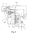
- Figure 4 shows a second mechanical and fluidic scheme of the power split transmission of Figure 1 , more adherent to a possible real construction. Such construction is substantially similar to that described in the publication US 2014/0174704A1 , to which reference is made concerning the detailed description of the mechanical and hydraulic construction and operation of the transmission.
- the first power branch PB1 of the transmission 1 comprises the hydrostatic pump 19 and the hydrostatic motor 19.
- the second power branch PB2 comprises a dual clutch transmission 50 comprising in its turn a first clutch 56 and a second clutch 57.
- the dual clutch transmission 50 can be connected permanently to the drive engine M on the input side, or reversibly connected to and disconnected from it through a clutch not shown.
- the input shaft 51 of the dual clutch transmission 50 is connected to the driven shaft 11 of the drive engine M via a second transmission stage.
- an output shaft 62 of the dual clutch transmission 50 is connected to the summing gear mechanism 9.
- the summing gear mechanism 9 therefore has two inputs which are connected permanently to the hydraulic motor 19 on one side and are connected permanently to the output shaft 62 of the dual clutch transmission 50 on the other side.
- at least one first transmission stage 53 and one second transmission stage 54 are configured in the dual clutch transmission 50. Both transmission stages 53, 54 are connected permanently to the output shaft 62 of the dual clutch transmission 50.
- the first clutch 56 and the second clutch 57 are provided in order to connect the transmission stage to be engaged in each case to an input shaft 51 of the dual clutch transmission 50.
- the two clutches 56, 57 are connected to in each case one clutch shaft 66', 67'.
- a further transmission stage 55 can be present provided for driving in reverse, in addition to the two transmission stages 53, 54.
- a selector sleeve 68 is provided, by way of which in each case one idler gear of the transmission stage for driving in reverse 55 or of the second transmission stage 54 can be connected in a rotationally fixed manner to the second clutch shaft 67'.
- the first transmission stage 53 is connected permanently to the first clutch shaft 66'.
- one of the clutches 56 is opened in the case of a rotationally fixed connection of the first transmission stage 53 to the first clutch shaft 66', whereas the other clutch is closed.
- both clutches 56, 57 are to be opened at the same time in the dual clutch transmission 50.
- a purely hydrostatic first driving range can therefore be realized.
- the summing gear mechanism 9 can be configured as a single planetary gear mechanism.
- single planetary gear mechanism means that there is merely one gear set.
- Said gear set contains a sun gear 69 as first transmission element, a spider 70 as second transmission element, and an internal gear 61 as third transmission element.
- the internal gear 61 is connected permanently in a rotationally fixed manner to the output shaft 62 of the dual clutch transmission 50.
- the sun gear 69 is connected permanently in a rotationally fixed manner to the output shaft 5 of the hydraulic motor 19.
- the spider is connected permanently in a rotationally fixed manner to the driven shaft 3 of the drive system 1.
- the output shaft 5 can likewise be connected to the driven shaft in a rotationally fixed manner via a third clutch 72..
- the output shaft 5 of the hydraulic motor 19 acts on the sun gear 69 via a transmission stage. Furthermore, a further transmission stage is provided between the sun gear shaft and the input side of the third clutch 72. The third clutch 72 interacts on the output side in turn with the driven shaft via a further transmission stage.
- the pressure in a suitable hydrostatic power circuit can be chosen as monitored variable Var, indicating the variation of the load applied at the output shaft 3 or at the shaft 11, for example the hydrostatic power circuit driving the wheels or tracks on which the vehicle runs.
- monitored variables Var indicating the variation of the load applied at the output shaft 3 or at the shaft 11, for example the hydrostatic power circuit driving the wheels or tracks on which the vehicle runs.
- the control unit 13 can monitor further variables for detecting situations entailing a sudden increase of the load applied to the ICE or for determining when a clutch 15A, 15B, 15C has to be reengaged after having disconnected all of them at the end of the period ⁇ T0.
- Such further variables can be for example the position of the drive pedal or the vehicle speed and its variations over the time: in fact the speed of a wheel loader entering a pile of incoherent material to be loaded in its bucket usually ranges between 5-10 km/h.
- the second power branch can be provided not only with three clutches 15A, 15B, 15C but also with a different number of clutches.
- the first power branch can be provided with a different continuous hydraulic variator or with yet further kinds of continuous variators, such as a mechanical or electrical continuous variator.
- continuous hydraulic variator or with yet further kinds of continuous variators, such as a mechanical or electrical continuous variator.
- all details are replaceable with technically equivalent elements.
- the used materials, as well as their dimensions, can be any according to the technical needs. It is to be intended that an expression such as "A comprises B, C, D” also comprises and describes the - particular case wherein "A consists of B, C, D” .
- the examples and lists of the possible variations of the present application are to be
Landscapes
- Engineering & Computer Science (AREA)
- General Engineering & Computer Science (AREA)
- Mechanical Engineering (AREA)
- Control Of Transmission Device (AREA)
Priority Applications (1)
| Application Number | Priority Date | Filing Date | Title |
|---|---|---|---|
| EP14425159.2A EP3040586A1 (de) | 2014-12-29 | 2014-12-29 | Leistungsverzweigendes Getriebe, Maschine mit solch einem Getriebe und Verfahren zum Betrieb solch eines Getriebes |
Applications Claiming Priority (1)
| Application Number | Priority Date | Filing Date | Title |
|---|---|---|---|
| EP14425159.2A EP3040586A1 (de) | 2014-12-29 | 2014-12-29 | Leistungsverzweigendes Getriebe, Maschine mit solch einem Getriebe und Verfahren zum Betrieb solch eines Getriebes |
Publications (1)
| Publication Number | Publication Date |
|---|---|
| EP3040586A1 true EP3040586A1 (de) | 2016-07-06 |
Family
ID=52462776
Family Applications (1)
| Application Number | Title | Priority Date | Filing Date |
|---|---|---|---|
| EP14425159.2A Withdrawn EP3040586A1 (de) | 2014-12-29 | 2014-12-29 | Leistungsverzweigendes Getriebe, Maschine mit solch einem Getriebe und Verfahren zum Betrieb solch eines Getriebes |
Country Status (1)
| Country | Link |
|---|---|
| EP (1) | EP3040586A1 (de) |
Cited By (1)
| Publication number | Priority date | Publication date | Assignee | Title |
|---|---|---|---|---|
| EP3779238A4 (de) * | 2018-04-10 | 2021-04-21 | Beijing Institute Of Technology | Stufenloses mechanisches zusammengesetztes getriebe mit drei abschnitten für konstruktionsmaschinen |
Citations (9)
| Publication number | Priority date | Publication date | Assignee | Title |
|---|---|---|---|---|
| US3714845A (en) | 1971-08-24 | 1973-02-06 | Gen Motors Corp | Hydromechanical transmission |
| JPH05280616A (ja) * | 1992-03-31 | 1993-10-26 | Shimadzu Corp | 無段変速機の変速制御装置 |
| US20030125147A1 (en) * | 2001-12-28 | 2003-07-03 | Lutgen F. Paul | Transmission control system and method |
| DE102007037107A1 (de) | 2006-08-16 | 2008-02-21 | Robert Bosch Gmbh | Verfahren zum Steuern eines Antriebssystems |
| DE102007037664A1 (de) | 2006-08-16 | 2008-02-21 | Robert Bosch Gmbh | Leistungsverzweigungsgetriebe und Verfahren zum Wechseln von Fahrbereichen |
| US20120174704A1 (en) | 2009-07-01 | 2012-07-12 | Robert Bosch Gmbh | Drive System and Method for Changing Driving Ranges of the Drive System |
| WO2013110707A1 (en) * | 2012-01-24 | 2013-08-01 | Spicer Off-Highway Belgium N.V. | A method for operating a vehicle driveline |
| US20140095035A1 (en) * | 2012-09-28 | 2014-04-03 | Caterpillar Inc. | System and Method for Avoiding Engine Underspeed and Stall |
| US20140174704A1 (en) | 2012-12-20 | 2014-06-26 | Asia Vital Components Co., Ltd. | Heat dissipation device |
-
2014
- 2014-12-29 EP EP14425159.2A patent/EP3040586A1/de not_active Withdrawn
Patent Citations (9)
| Publication number | Priority date | Publication date | Assignee | Title |
|---|---|---|---|---|
| US3714845A (en) | 1971-08-24 | 1973-02-06 | Gen Motors Corp | Hydromechanical transmission |
| JPH05280616A (ja) * | 1992-03-31 | 1993-10-26 | Shimadzu Corp | 無段変速機の変速制御装置 |
| US20030125147A1 (en) * | 2001-12-28 | 2003-07-03 | Lutgen F. Paul | Transmission control system and method |
| DE102007037107A1 (de) | 2006-08-16 | 2008-02-21 | Robert Bosch Gmbh | Verfahren zum Steuern eines Antriebssystems |
| DE102007037664A1 (de) | 2006-08-16 | 2008-02-21 | Robert Bosch Gmbh | Leistungsverzweigungsgetriebe und Verfahren zum Wechseln von Fahrbereichen |
| US20120174704A1 (en) | 2009-07-01 | 2012-07-12 | Robert Bosch Gmbh | Drive System and Method for Changing Driving Ranges of the Drive System |
| WO2013110707A1 (en) * | 2012-01-24 | 2013-08-01 | Spicer Off-Highway Belgium N.V. | A method for operating a vehicle driveline |
| US20140095035A1 (en) * | 2012-09-28 | 2014-04-03 | Caterpillar Inc. | System and Method for Avoiding Engine Underspeed and Stall |
| US20140174704A1 (en) | 2012-12-20 | 2014-06-26 | Asia Vital Components Co., Ltd. | Heat dissipation device |
Cited By (1)
| Publication number | Priority date | Publication date | Assignee | Title |
|---|---|---|---|---|
| EP3779238A4 (de) * | 2018-04-10 | 2021-04-21 | Beijing Institute Of Technology | Stufenloses mechanisches zusammengesetztes getriebe mit drei abschnitten für konstruktionsmaschinen |
Similar Documents
| Publication | Publication Date | Title |
|---|---|---|
| US9097342B2 (en) | Method for estimating and controlling driveline torque in a continuously variable hydro-mechanical transmission | |
| EP2264334B1 (de) | Hybridgetriebe und Betriebsverfahren eines solchen Getriebes | |
| CN108282999B (zh) | 用于具有作业机具的机器的牵引力控制系统和方法 | |
| US10427670B2 (en) | Supplemental hydraulic motor for continuously variable transmission | |
| EP2194297B1 (de) | Nutzfahrzeug | |
| DE102015220635A1 (de) | Antriebsstranganordnung für ein Arbeitsfahrzeug mit einem Motor | |
| DE112011103898T5 (de) | Verfahren zum Synchronisieren bei einem stufenlosen Doppelkupplungsgetriebe mit Drehmomentverzweigung | |
| US5402879A (en) | Drive system for flight conveyors and method of operating same | |
| EP3770336B1 (de) | Verfahren zur reduzierung des kraftstoffverbrauchs in ladern, baggern, tieflöffelbaggern und dergleichen | |
| EP2807404B1 (de) | Verfahren zum betreiben einer fahrzeugantriebsleitung | |
| US6595885B1 (en) | Transmission control system and method | |
| US8838345B2 (en) | Automatic transmission system for bulldozer | |
| US20160169304A1 (en) | System and Method for Preventing Centrifugal Clutch Lock-Ups Within a Transmission of a Work Vehicle | |
| US20150198242A1 (en) | Method and Controller for a Powertrain in a Machine | |
| US7631494B2 (en) | Hydrostatic transmission of a hydrostatic-mechanical power distribution transmission | |
| EP2087253A1 (de) | Verfahren und system zur steuerung eines fahrzeugs | |
| EP2644948B1 (de) | Vorrichtung und Verfahren zur Steuerung des Drucks von Hydraulikflüssigkeit, die in einem Arbeitsfahrzeuggetriebe gefördert wird | |
| US10183671B2 (en) | Torque converter lockup control | |
| CN103883724B (zh) | 一种平地机换档控制方法、系统及平地机 | |
| CN203878634U (zh) | 一种平地机换挡控制系统及平地机 | |
| US20160017992A1 (en) | Hydraulic Parallel Path Continuously Variable Transmission | |
| US12385222B2 (en) | Powertrain eco-mode for work machines | |
| RU2294850C2 (ru) | Муфта сцепления с пневмогидравлическим упругим элементом | |
| JP2879710B2 (ja) | 流体・桟械動力を出力するトルクコンバータおよびその制御方法 | |
| US8550960B2 (en) | Method for the operation of a clutch of a hydrodynamic torque converter |
Legal Events
| Date | Code | Title | Description |
|---|---|---|---|
| PUAI | Public reference made under article 153(3) epc to a published international application that has entered the european phase |
Free format text: ORIGINAL CODE: 0009012 |
|
| AK | Designated contracting states |
Kind code of ref document: A1 Designated state(s): AL AT BE BG CH CY CZ DE DK EE ES FI FR GB GR HR HU IE IS IT LI LT LU LV MC MK MT NL NO PL PT RO RS SE SI SK SM TR |
|
| AX | Request for extension of the european patent |
Extension state: BA ME |
|
| STAA | Information on the status of an ep patent application or granted ep patent |
Free format text: STATUS: THE APPLICATION HAS BEEN PUBLISHED |
|
| STAA | Information on the status of an ep patent application or granted ep patent |
Free format text: STATUS: THE APPLICATION IS DEEMED TO BE WITHDRAWN |
|
| 18D | Application deemed to be withdrawn |
Effective date: 20170110 |