EP3040528B1 - Construction machine - Google Patents
Construction machine Download PDFInfo
- Publication number
- EP3040528B1 EP3040528B1 EP14839362.2A EP14839362A EP3040528B1 EP 3040528 B1 EP3040528 B1 EP 3040528B1 EP 14839362 A EP14839362 A EP 14839362A EP 3040528 B1 EP3040528 B1 EP 3040528B1
- Authority
- EP
- European Patent Office
- Prior art keywords
- regeneration
- exhaust gas
- filter
- regeneration treatment
- estimated
- Prior art date
- Legal status (The legal status is an assumption and is not a legal conclusion. Google has not performed a legal analysis and makes no representation as to the accuracy of the status listed.)
- Active
Links
- 238000010276 construction Methods 0.000 title claims description 17
- 230000008929 regeneration Effects 0.000 claims description 326
- 238000011069 regeneration method Methods 0.000 claims description 326
- 239000013618 particulate matter Substances 0.000 claims description 106
- 238000002347 injection Methods 0.000 claims description 71
- 239000007924 injection Substances 0.000 claims description 71
- 239000000446 fuel Substances 0.000 claims description 67
- 239000007789 gas Substances 0.000 description 173
- 238000000034 method Methods 0.000 description 59
- 230000008569 process Effects 0.000 description 59
- MWUXSHHQAYIFBG-UHFFFAOYSA-N nitrogen oxide Inorganic materials O=[N] MWUXSHHQAYIFBG-UHFFFAOYSA-N 0.000 description 23
- 239000003921 oil Substances 0.000 description 14
- 239000003054 catalyst Substances 0.000 description 13
- 238000004364 calculation method Methods 0.000 description 12
- 230000003647 oxidation Effects 0.000 description 12
- 238000007254 oxidation reaction Methods 0.000 description 12
- 229910002091 carbon monoxide Inorganic materials 0.000 description 10
- 239000010705 motor oil Substances 0.000 description 8
- 238000010790 dilution Methods 0.000 description 7
- 239000012895 dilution Substances 0.000 description 7
- 230000007246 mechanism Effects 0.000 description 7
- 239000004215 Carbon black (E152) Substances 0.000 description 6
- 230000008859 change Effects 0.000 description 6
- 238000002474 experimental method Methods 0.000 description 6
- 229930195733 hydrocarbon Natural products 0.000 description 6
- 150000002430 hydrocarbons Chemical class 0.000 description 6
- 238000004088 simulation Methods 0.000 description 6
- UGFAIRIUMAVXCW-UHFFFAOYSA-N Carbon monoxide Chemical class [O+]#[C-] UGFAIRIUMAVXCW-UHFFFAOYSA-N 0.000 description 5
- 238000009825 accumulation Methods 0.000 description 5
- 230000000052 comparative effect Effects 0.000 description 5
- 230000004044 response Effects 0.000 description 5
- 239000000126 substance Substances 0.000 description 5
- 238000011144 upstream manufacturing Methods 0.000 description 5
- 230000006866 deterioration Effects 0.000 description 4
- 238000010586 diagram Methods 0.000 description 4
- 239000002828 fuel tank Substances 0.000 description 4
- 239000007787 solid Substances 0.000 description 4
- 230000001629 suppression Effects 0.000 description 4
- 238000001514 detection method Methods 0.000 description 3
- 238000006073 displacement reaction Methods 0.000 description 3
- 230000009467 reduction Effects 0.000 description 3
- 238000002485 combustion reaction Methods 0.000 description 2
- 238000002156 mixing Methods 0.000 description 2
- 230000001590 oxidative effect Effects 0.000 description 2
- 230000000630 rising effect Effects 0.000 description 2
- 239000004576 sand Substances 0.000 description 2
- JCXJVPUVTGWSNB-UHFFFAOYSA-N Nitrogen dioxide Chemical class O=[N]=O JCXJVPUVTGWSNB-UHFFFAOYSA-N 0.000 description 1
- XSQUKJJJFZCRTK-UHFFFAOYSA-N Urea Chemical compound NC(N)=O XSQUKJJJFZCRTK-UHFFFAOYSA-N 0.000 description 1
- 230000004913 activation Effects 0.000 description 1
- 239000004202 carbamide Substances 0.000 description 1
- 239000000919 ceramic Substances 0.000 description 1
- 229910010293 ceramic material Inorganic materials 0.000 description 1
- 238000006243 chemical reaction Methods 0.000 description 1
- 239000000498 cooling water Substances 0.000 description 1
- 238000007599 discharging Methods 0.000 description 1
- 230000006870 function Effects 0.000 description 1
- 229910000510 noble metal Inorganic materials 0.000 description 1
- 238000011112 process operation Methods 0.000 description 1
- 238000000746 purification Methods 0.000 description 1
- 230000001172 regenerating effect Effects 0.000 description 1
- 238000005070 sampling Methods 0.000 description 1
Images


Classifications
-
- F—MECHANICAL ENGINEERING; LIGHTING; HEATING; WEAPONS; BLASTING
- F01—MACHINES OR ENGINES IN GENERAL; ENGINE PLANTS IN GENERAL; STEAM ENGINES
- F01N—GAS-FLOW SILENCERS OR EXHAUST APPARATUS FOR MACHINES OR ENGINES IN GENERAL; GAS-FLOW SILENCERS OR EXHAUST APPARATUS FOR INTERNAL COMBUSTION ENGINES
- F01N9/00—Electrical control of exhaust gas treating apparatus
- F01N9/002—Electrical control of exhaust gas treating apparatus of filter regeneration, e.g. detection of clogging
-
- F—MECHANICAL ENGINEERING; LIGHTING; HEATING; WEAPONS; BLASTING
- F01—MACHINES OR ENGINES IN GENERAL; ENGINE PLANTS IN GENERAL; STEAM ENGINES
- F01N—GAS-FLOW SILENCERS OR EXHAUST APPARATUS FOR MACHINES OR ENGINES IN GENERAL; GAS-FLOW SILENCERS OR EXHAUST APPARATUS FOR INTERNAL COMBUSTION ENGINES
- F01N3/00—Exhaust or silencing apparatus having means for purifying, rendering innocuous, or otherwise treating exhaust
- F01N3/02—Exhaust or silencing apparatus having means for purifying, rendering innocuous, or otherwise treating exhaust for cooling, or for removing solid constituents of, exhaust
- F01N3/021—Exhaust or silencing apparatus having means for purifying, rendering innocuous, or otherwise treating exhaust for cooling, or for removing solid constituents of, exhaust by means of filters
- F01N3/023—Exhaust or silencing apparatus having means for purifying, rendering innocuous, or otherwise treating exhaust for cooling, or for removing solid constituents of, exhaust by means of filters using means for regenerating the filters, e.g. by burning trapped particles
- F01N3/0235—Exhaust or silencing apparatus having means for purifying, rendering innocuous, or otherwise treating exhaust for cooling, or for removing solid constituents of, exhaust by means of filters using means for regenerating the filters, e.g. by burning trapped particles using exhaust gas throttling means
-
- F—MECHANICAL ENGINEERING; LIGHTING; HEATING; WEAPONS; BLASTING
- F01—MACHINES OR ENGINES IN GENERAL; ENGINE PLANTS IN GENERAL; STEAM ENGINES
- F01N—GAS-FLOW SILENCERS OR EXHAUST APPARATUS FOR MACHINES OR ENGINES IN GENERAL; GAS-FLOW SILENCERS OR EXHAUST APPARATUS FOR INTERNAL COMBUSTION ENGINES
- F01N3/00—Exhaust or silencing apparatus having means for purifying, rendering innocuous, or otherwise treating exhaust
- F01N3/02—Exhaust or silencing apparatus having means for purifying, rendering innocuous, or otherwise treating exhaust for cooling, or for removing solid constituents of, exhaust
- F01N3/021—Exhaust or silencing apparatus having means for purifying, rendering innocuous, or otherwise treating exhaust for cooling, or for removing solid constituents of, exhaust by means of filters
- F01N3/033—Exhaust or silencing apparatus having means for purifying, rendering innocuous, or otherwise treating exhaust for cooling, or for removing solid constituents of, exhaust by means of filters in combination with other devices
- F01N3/035—Exhaust or silencing apparatus having means for purifying, rendering innocuous, or otherwise treating exhaust for cooling, or for removing solid constituents of, exhaust by means of filters in combination with other devices with catalytic reactors, e.g. catalysed diesel particulate filters
-
- F—MECHANICAL ENGINEERING; LIGHTING; HEATING; WEAPONS; BLASTING
- F01—MACHINES OR ENGINES IN GENERAL; ENGINE PLANTS IN GENERAL; STEAM ENGINES
- F01N—GAS-FLOW SILENCERS OR EXHAUST APPARATUS FOR MACHINES OR ENGINES IN GENERAL; GAS-FLOW SILENCERS OR EXHAUST APPARATUS FOR INTERNAL COMBUSTION ENGINES
- F01N3/00—Exhaust or silencing apparatus having means for purifying, rendering innocuous, or otherwise treating exhaust
- F01N3/08—Exhaust or silencing apparatus having means for purifying, rendering innocuous, or otherwise treating exhaust for rendering innocuous
- F01N3/10—Exhaust or silencing apparatus having means for purifying, rendering innocuous, or otherwise treating exhaust for rendering innocuous by thermal or catalytic conversion of noxious components of exhaust
- F01N3/105—General auxiliary catalysts, e.g. upstream or downstream of the main catalyst
- F01N3/106—Auxiliary oxidation catalysts
-
- F—MECHANICAL ENGINEERING; LIGHTING; HEATING; WEAPONS; BLASTING
- F02—COMBUSTION ENGINES; HOT-GAS OR COMBUSTION-PRODUCT ENGINE PLANTS
- F02D—CONTROLLING COMBUSTION ENGINES
- F02D41/00—Electrical control of supply of combustible mixture or its constituents
- F02D41/02—Circuit arrangements for generating control signals
- F02D41/021—Introducing corrections for particular conditions exterior to the engine
- F02D41/0235—Introducing corrections for particular conditions exterior to the engine in relation with the state of the exhaust gas treating apparatus
- F02D41/027—Introducing corrections for particular conditions exterior to the engine in relation with the state of the exhaust gas treating apparatus to purge or regenerate the exhaust gas treating apparatus
- F02D41/029—Introducing corrections for particular conditions exterior to the engine in relation with the state of the exhaust gas treating apparatus to purge or regenerate the exhaust gas treating apparatus the exhaust gas treating apparatus being a particulate filter
-
- F—MECHANICAL ENGINEERING; LIGHTING; HEATING; WEAPONS; BLASTING
- F02—COMBUSTION ENGINES; HOT-GAS OR COMBUSTION-PRODUCT ENGINE PLANTS
- F02D—CONTROLLING COMBUSTION ENGINES
- F02D41/00—Electrical control of supply of combustible mixture or its constituents
- F02D41/02—Circuit arrangements for generating control signals
- F02D41/14—Introducing closed-loop corrections
- F02D41/1438—Introducing closed-loop corrections using means for determining characteristics of the combustion gases; Sensors therefor
- F02D41/1444—Introducing closed-loop corrections using means for determining characteristics of the combustion gases; Sensors therefor characterised by the characteristics of the combustion gases
- F02D41/1446—Introducing closed-loop corrections using means for determining characteristics of the combustion gases; Sensors therefor characterised by the characteristics of the combustion gases the characteristics being exhaust temperatures
-
- F—MECHANICAL ENGINEERING; LIGHTING; HEATING; WEAPONS; BLASTING
- F02—COMBUSTION ENGINES; HOT-GAS OR COMBUSTION-PRODUCT ENGINE PLANTS
- F02D—CONTROLLING COMBUSTION ENGINES
- F02D41/00—Electrical control of supply of combustible mixture or its constituents
- F02D41/30—Controlling fuel injection
- F02D41/38—Controlling fuel injection of the high pressure type
- F02D41/40—Controlling fuel injection of the high pressure type with means for controlling injection timing or duration
- F02D41/402—Multiple injections
- F02D41/405—Multiple injections with post injections
-
- F—MECHANICAL ENGINEERING; LIGHTING; HEATING; WEAPONS; BLASTING
- F01—MACHINES OR ENGINES IN GENERAL; ENGINE PLANTS IN GENERAL; STEAM ENGINES
- F01N—GAS-FLOW SILENCERS OR EXHAUST APPARATUS FOR MACHINES OR ENGINES IN GENERAL; GAS-FLOW SILENCERS OR EXHAUST APPARATUS FOR INTERNAL COMBUSTION ENGINES
- F01N2430/00—Influencing exhaust purification, e.g. starting of catalytic reaction, filter regeneration, or the like, by controlling engine operating characteristics
- F01N2430/08—Influencing exhaust purification, e.g. starting of catalytic reaction, filter regeneration, or the like, by controlling engine operating characteristics by modifying ignition or injection timing
- F01N2430/085—Influencing exhaust purification, e.g. starting of catalytic reaction, filter regeneration, or the like, by controlling engine operating characteristics by modifying ignition or injection timing at least a part of the injection taking place during expansion or exhaust stroke
-
- F—MECHANICAL ENGINEERING; LIGHTING; HEATING; WEAPONS; BLASTING
- F01—MACHINES OR ENGINES IN GENERAL; ENGINE PLANTS IN GENERAL; STEAM ENGINES
- F01N—GAS-FLOW SILENCERS OR EXHAUST APPARATUS FOR MACHINES OR ENGINES IN GENERAL; GAS-FLOW SILENCERS OR EXHAUST APPARATUS FOR INTERNAL COMBUSTION ENGINES
- F01N2590/00—Exhaust or silencing apparatus adapted to particular use, e.g. for military applications, airplanes, submarines
- F01N2590/08—Exhaust or silencing apparatus adapted to particular use, e.g. for military applications, airplanes, submarines for heavy duty applications, e.g. trucks, buses, tractors, locomotives
-
- F—MECHANICAL ENGINEERING; LIGHTING; HEATING; WEAPONS; BLASTING
- F01—MACHINES OR ENGINES IN GENERAL; ENGINE PLANTS IN GENERAL; STEAM ENGINES
- F01N—GAS-FLOW SILENCERS OR EXHAUST APPARATUS FOR MACHINES OR ENGINES IN GENERAL; GAS-FLOW SILENCERS OR EXHAUST APPARATUS FOR INTERNAL COMBUSTION ENGINES
- F01N2900/00—Details of electrical control or of the monitoring of the exhaust gas treating apparatus
- F01N2900/06—Parameters used for exhaust control or diagnosing
- F01N2900/14—Parameters used for exhaust control or diagnosing said parameters being related to the exhaust gas
- F01N2900/1404—Exhaust gas temperature
-
- F—MECHANICAL ENGINEERING; LIGHTING; HEATING; WEAPONS; BLASTING
- F01—MACHINES OR ENGINES IN GENERAL; ENGINE PLANTS IN GENERAL; STEAM ENGINES
- F01N—GAS-FLOW SILENCERS OR EXHAUST APPARATUS FOR MACHINES OR ENGINES IN GENERAL; GAS-FLOW SILENCERS OR EXHAUST APPARATUS FOR INTERNAL COMBUSTION ENGINES
- F01N2900/00—Details of electrical control or of the monitoring of the exhaust gas treating apparatus
- F01N2900/06—Parameters used for exhaust control or diagnosing
- F01N2900/16—Parameters used for exhaust control or diagnosing said parameters being related to the exhaust apparatus, e.g. particulate filter or catalyst
- F01N2900/1606—Particle filter loading or soot amount
-
- F—MECHANICAL ENGINEERING; LIGHTING; HEATING; WEAPONS; BLASTING
- F02—COMBUSTION ENGINES; HOT-GAS OR COMBUSTION-PRODUCT ENGINE PLANTS
- F02D—CONTROLLING COMBUSTION ENGINES
- F02D2200/00—Input parameters for engine control
- F02D2200/02—Input parameters for engine control the parameters being related to the engine
- F02D2200/08—Exhaust gas treatment apparatus parameters
- F02D2200/0812—Particle filter loading
-
- Y—GENERAL TAGGING OF NEW TECHNOLOGICAL DEVELOPMENTS; GENERAL TAGGING OF CROSS-SECTIONAL TECHNOLOGIES SPANNING OVER SEVERAL SECTIONS OF THE IPC; TECHNICAL SUBJECTS COVERED BY FORMER USPC CROSS-REFERENCE ART COLLECTIONS [XRACs] AND DIGESTS
- Y02—TECHNOLOGIES OR APPLICATIONS FOR MITIGATION OR ADAPTATION AGAINST CLIMATE CHANGE
- Y02T—CLIMATE CHANGE MITIGATION TECHNOLOGIES RELATED TO TRANSPORTATION
- Y02T10/00—Road transport of goods or passengers
- Y02T10/10—Internal combustion engine [ICE] based vehicles
- Y02T10/40—Engine management systems
Definitions
- the present invention relates to a construction machine that is provided with an exhaust gas purifying device suitable for removing harmful substances from an exhaust gas in a diesel engine, for example, or the like.
- a construction machine such as a hydraulic excavator or a hydraulic crane is configured by an automotive lower travelling structure, an upper revolving structure mounted on the lower travelling structure to be capable of revolving thereon, and a working mechanism tiltably mounted on a front side of the upper revolving structure.
- the upper revolving structure mounts an engine on a rear part in a revolving frame for driving a hydraulic pump, and mounts a cab, a fuel tank, an operating oil tank and the like on a front side in the revolving frame.
- a diesel engine is generally used as an engine that is a prime mover of a construction machine.
- harmful substances such as particulate matter (PM), nitrogen oxides (NOx) and the like are contained in an exhaust gas discharged from such a diesel engine. Therefore, the construction machine is provided with an exhaust gas purifying device in an exhaust pipe forming an exhaust gas passage of the engine for purifying an exhaust gas therein.
- the exhaust gas purifying device is configured by an oxidation catalyst (for example, diesel oxidation catalyst, referred to as "DOC” for short) for oxidizing and removing nitrogen monoxides (NO), carbon monoxides (CO), hydrocarbon (HC) and the like that are contained in an exhaust gas, and a particulate matter removing filter (for example, diesel particulate filter, referred to as "DPF” for short) that is arranged downstream side of the oxidation catalyst for trapping and removing particulate matter in the exhaust gas (Patent Document 1).
- DOC diesel oxidation catalyst
- DPF diesel particulate filter
- the particulate matter removing filter in the particulate matter removing filter, the particulate matter is accumulated therein following the trapping of the particulate matter, which might cause the filter to be clogged. Therefore, it is necessary to remove the particulate matter from the filter in a point where a predetermined amount of the particulate matter is trapped for regenerating the filter.
- This regeneration treatment of the filter can be performed in such a manner that fuel injection for regeneration treatment called "post injection" is performed to increase a temperature of an exhaust gas for burning the particulate matter that is accumulated in the filter.
- the conventional art is configured such that a trapping amount of the particulate matter trapped in the filter is estimated (calculated) and the regeneration treatment is automatically executed before the estimated trapping amount becomes excessively large, that is, when the estimated trapping amount reaches a predetermined threshold (Patent Document 2).
- the regeneration treatment of the filter in a case where the regeneration treatment of the filter is executed, for example, when the construction machine performs a light-load work or when the construction machine is kept in a low rotational state (low idle state) where a rotational number (rotational speed) of an engine is low (on standby), a temperature of an exhaust gas does not rise sufficiently. Therefore, even if the regeneration treatment continues to be executed, there is a possibility that the particulate matter cannot be sufficiently burned and removed. Accordingly, it is preferable that the regeneration treatment automatically terminates when the temperature of the exhaust gas is low. However, in a case of simply terminating the regeneration treatment, the regeneration treatment terminates in a state where the particulate matter burns slightly. As a result, in a case where the light-load work or the standby in the state of the low rotational state of the engine is kept, the regeneration operation and the regular operation are possibly alternately repeated by short intervals.
- This repetition possibly leads to, for example, an increase in fuel consumption quantity with an increase of post injections, excessive accumulation of particulate matter due to insufficient burning of the particulate matter and deterioration of working conditions by the exhaust gas.
- uncomfortable feelings are possibly given to an operator following a change in engine sounds at the time of switching the regular operation and the regeneration operation.
- fuel having adhered to a cylinder inner wall of an engine due to the post injection falls down into an oil pan, the fuel is then mixed with engine oil, leading to dilution of the engine oil (oil dilution).
- the present invention is made in view of a problem of the foregoing conventional art, and an object of the present invention is to provide a construction machine that can suppress a regeneration operation and a regular operation from being alternately repeated by short intervals.
- the restart terminated value is set between the regeneration start value and the normal terminated value.
- the restart terminated value as a threshold of the estimated trapping amount in a case of terminating the restarted regeneration treatment is set to be larger than the normal terminated value as a threshold of the estimated trapping amount in a case where the regeneration treatment normally terminates without the interruption. Therefore, even in a case where the exhaust gas temperature tends to be difficult in rising due to the continuation of the light-load work or the standby (neglect) in the low rotational state, it is possible to suppress the regeneration treatment restarted based upon the determination of the regeneration restart determining unit from excessively continuing (the regeneration time from being longer).
- Fig. 1 to Fig. 6 show a first embodiment of the present invention.
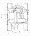
- the hydraulic excavator 1 includes a crawler type of automotive lower traveling structure 2, an upper revolving structure 4 that is mounted through a revolving device 3 on the lower traveling structure 2 to be capable of revolving thereon and configures a vehicle body together with the lower traveling structure 2, and a working mechanism 5 that is tiltably provided in a front side of the upper revolving structure 4.
- the working mechanism 5 is configured as a swing post type working mechanism, and is provided with, for example, a swing post 5A, a boom 5B, an arm 5C, a bucket 5D as a working tool, a swing cylinder 5E (refer to Fig. 2 ) for swinging the working mechanism 5 in the left-right direction, a boom cylinder 5F, an arm cylinder 5G, and a bucket cylinder 5H.
- the upper revolving structure 4 includes a revolving frame 6, an exterior cover 7, a cab 8, and a counterweight 9, which will be described later.
- the revolving frame 6 forms part of a structure of the upper revolving structure 4.
- the revolving frame 6 is mounted through the revolving device 3 on the lower traveling structure 2.
- the revolving frame 6 is provided with the counterweight 9 and the engine 10 in the rear part side, which will be described later, the cab 8 in the left front side which will be described later, and a fuel tank 16 in the right front side which will be described later.
- the revolving frame 6 is provided with the exterior cover 7 that is positioned from the right side to the rear side of the cab 8. This exterior cover 7 defines therein a space that accommodates the engine 10, a hydraulic pump 15, a heat exchanger 17, an exhaust gas purifying device 18 and the like, together with the revolving frame 6, the cab 8 and the counterweight 9.
- the cab 8 is mounted in the left front side of the revolving frame 6, and the cab 8 defines therein an operator's room in which an operator gets.
- An operator's seat on which the operator is seated, various operational levers and the like (any thereof is not shown) are disposed inside the cab 8.
- the counterweight 9 acts as a weight balance to the working mechanism 5.
- the counterweight 9 is mounted at the rear end part of the revolving frame 6 to be positioned in the rear side of the engine 10 which will be described later. As shown in Fig. 2 , the counterweight 9 is formed in a circular shape on the rear surface side.
- the counterweight 9 is configured to be accommodated within a vehicle width of the lower traveling structure 2.
- the engine 10 is the engine mounted in the rear side of the revolving frame 6 in a transversely placed state.
- the engine 10 is mounted on the compact hydraulic excavator 1 as a prime mover, and is therefore configured by a compact diesel engine, for example.
- the engine 10 is provided with an intake pipe 11 for taking in outside air (refer to Fig. 3 ) and an exhaust pipe 12 forming a part of an exhaust gas passage for discharging an exhaust gas. Outside air flows into the intake pipe 11 toward the engine 10, and an air cleaner 13 is connected to the intake pipe 11 in a tip end side for purifying the outside air.
- the exhaust gas purifying device 18 which will be described later is provided to be connected to the exhaust pipe 12.
- the engine 10 is driven by injection of fuel.
- the engine 10 is configured by an electronically controlled engine, and a supply quantity of fuel thereto is variably controlled by a fuel injection device 14 (refer to Fig. 3 ) including an electronically controlled injection valve. That is, the fuel injection device 14 variably controls an injection quantity of fuel injected into a cylinder (not shown) of the engine 10 based upon a control signal that is output from a controller 27 which will be described later.
- the fuel injection device 14 configures part of a regeneration device 22 together with the controller 27 which will be described later and the like (refer to Fig. 3 ).
- the fuel injection device 14 performs fuel injection for regeneration treatment, for example, called "post injection” (additional injection after combustion process) in response to a control signal from the controller 27.
- This post injection increases a temperature of an exhaust gas to burn and remove particulate matter accumulated in a particulate matter removing filter 21 in the exhaust gas purifying device 18 which will be described later.
- the hydraulic pump 15 is mounted to the left side of the engine 10.
- the hydraulic pump 15 forms part of a hydraulic source together with an operating oil tank (not shown).
- the hydraulic pump 15 is driven by the engine 10 to eject pressurized oil (operating oil) toward a control valve (not shown).
- the hydraulic pump 15 is configured by, for example, a swash plate type, bent axis type or radial piston type hydraulic pump of a variable displacement type. It should be noted that the hydraulic pump 15 is not necessarily limited to the hydraulic pump of a variable displacement type, but may be configured by using a hydraulic pump of a fixed displacement type.
- the fuel tank 16 is provided on the revolving frame 6 to be positioned to the right side of the cab 8, and is covered with the exterior cover 7 together with the unshown operating oil tank and the like.
- the fuel tank 16 is formed, for example, as a cubic pressure tight tank and reserves therein fuel to be supplied to the engine 10.
- the heat exchanger 17 is provided on the revolving frame 6 to be positioned to the right side of the engine 10.
- the heat exchanger 17 is configured by, for example, a radiator, an oil cooler, and an intercooler. That is, the heat exchanger 17 cools cooling water of the engine 10, as well as pressurized oil that is returned back to the operating oil tank.
- the exhaust gas purifying device 18 is the exhaust gas purifying device that is provided in the exhaust side of the engine 10. As shown in Fig. 2 , the exhaust gas purifying device 18 is arranged in the upper part left side of the engine 10 in a position above the hydraulic pump 15, for example, and is connected at the upstream side to the exhaust pipe 12 of the engine 10. The exhaust gas purifying device 18 forms part of an exhaust gas passage together with the exhaust pipe 12 and removes harmful substances contained in an exhaust gas during a period where the exhaust gas flows from the upstream side to the downstream side therein.
- the engine 10 comprising the diesel engine has a high efficiency and is excellent in durability, but harmful substances such as particulate matter (PM), nitrogen oxides (NOx), and carbon monoxides (CO) and the like are contained in the exhaust gas from the engine 10. Therefore, as shown in Fig. 3 , the exhaust gas purifying device 18 mounted on the exhaust pipe 12 is configured by an oxidation catalyst 20 for oxidizing and removing carbon monoxides (CO) or the like in the exhaust gas and the particulate matter removing filter 21, which will be described later, for trapping and removing the particulate matter (PM) in the exhaust gas.
- an oxidation catalyst 20 for oxidizing and removing carbon monoxides (CO) or the like in the exhaust gas
- the particulate matter removing filter 21 which will be described later
- the exhaust gas purifying device 18 is provided with a cylindrical casing 19 configured by removably connecting a plurality of cylinders in the front and rear direction, for example.
- the oxidation catalyst 20 called “DOC” and the particulate matter removing filter 21 called “DPF” (hereinafter called “filter 21”) are removably accommodated in the casing 19.
- An outlet port 19A is connected to an outlet side of the casing 19 to be positioned downstream of the filter 21.
- This outlet port 19A is configured by, for example, a chimney for releasing the purified exhaust gas into an atmosphere, and a muffling device.
- the oxidation catalyst 20 comprises a cell-shaped cylindrical body made of ceramic having an outer diameter dimension that is equivalent to an inner diameter dimension of the casing 19, for example. Many through holes (not shown) are axially formed in the oxidation catalyst 20, an inner surface of which is coated with noble metals.
- the oxidation catalyst 20 oxidizes and removes carbon monoxides (CO), hydrocarbon (HC), and the like contained in the exhaust gas by circulating the exhaust gas into each through hole under a predetermined temperature condition, and, for example, removes nitrogen monoxide (NO) as nitrogen dioxides (NO 2 ).
- the filter 21 is arranged downstream side of the oxidation catalyst 20 in the casing 19.
- the filter 21 traps particulate matter in the exhaust gas discharged from the engine 10, and burns and removes the trapped particulate matter to perform purification of the exhaust gas. Therefore, the filter 21 is configured by a cell-shaped cylindrical body which is, for example, a porous member made of a ceramic material, having many small bores (not shown) in an axial direction. Thereby, the filter 21 traps particulate matter through many small bores, and the trapped particulate matter is burned and removed by regeneration treatment of the regeneration device 22 which will be described later. As a result, the filter 21 is regenerated.
- the regeneration device 22 includes the aforementioned fuel injection device 14, a rotational sensor 23, pressure sensors 24 and 25, an exhaust gas temperature sensor 26, and the controller 27, which will be described later.
- the regeneration device 22 automatically executes the regeneration treatment based upon the determination of the controller 27, that is, not based upon an operation by an operator.
- the regeneration device 22 performs a post injection by the fuel injection device 14 in response to a command signal (control signal) of the controller 27. This post injection increases a temperature of an exhaust gas in the exhaust pipe 12 to burn and remove the particulate matter accumulated in the filter 21.
- the rotational sensor 23 detects a rotational number (rotational speed) N of the engine 10, and the rotational sensor 23 detects the rotational number N of the engine 10 and outputs the detection signal to the controller 27 which will be described later.
- the controller 27 estimates a trapping amount of the particulate matter trapped in the filter 21 based upon an engine rotational number N detected by the rotational sensor 23, a fuel injection quantity F injected by the fuel injection device 14, and an exhaust temperature (exhaust gas temperature) T detected by the exhaust gas temperature sensor 26 which will be described later. Further, the controller 27 determines whether or not the regeneration treatment is executed based upon a first estimated trapping amount H1 which is the estimated trapping amount.
- the fuel injection quantity F can be found, for example, from an intake air quantity detected from an unshown air flow meter provided in the intake side of the engine 10 and an engine rotational number N, and besides, can be calculated also from a control signal (fuel injection command) that is output to the fuel injection device 14 from the controller 27, for example.
- the pressure sensors 24 and 25 are provided in the casing 19 in the exhaust gas purifying device 18. As shown in Fig. 3 , the pressure sensor 24 is arranged at an inlet side (upstream side) of the filter 21 and the pressure sensor 25 is arranged at an outlet side (downstream side) of the filter 21, which output the respective detection signals to the controller 27 which will be described later.
- the controller 27 calculates a differential pressure ⁇ P between a pressure P1 in the inlet side detected by the pressure sensor 24 and a pressure P2 in the outlet side detected by the pressure sensor 25, and estimates a trapping amount of the particulate matter in the filter 21 based upon the differential pressure ⁇ P, an exhaust gas temperature T, and an exhaust gas flow amount, and determines whether or not the regeneration treatment is executed based upon a second estimated trapping amount H2 that is the estimated trapping amount.
- the exhaust gas temperature sensor 26 is a temperature detector that detects a temperature (exhaust gas temperature) T of an exhaust gas discharged from the engine 10. As shown in Fig. 3 , the exhaust gas temperature sensor 26 is mounted to the casing 19 in the exhaust gas purifying device 18, and detects a temperature T of an exhaust gas discharged from the exhaust pipe 12 side, for example. The exhaust gas temperature T upstream of the filter 21 detected by the exhaust gas temperature sensor 26 is output to the controller 27, which will be described later, as a detection signal. The exhaust gas temperature T is used for estimation of a trapping amount of the particulate matter trapped in the filter 21, determination of interruption and the restart of the regeneration treatment, and the like.
- the controller 27 includes a microcomputer, and the controller 27 is connected at the input side to the fuel injection device 14, the rotational sensor 23, the pressure sensors 24 and 25, the exhaust gas temperature sensor 26, the unshown air flow meter, and the like.
- the controller 27 is connected at the output side to the fuel injection device 14, and the like.
- the controller 27 has a memory 27A including a ROM and a RAM. Process programs for regeneration treatment shown in Fig. 4 and Fig. 5 which will be described later, a first map and a second map in advance produced for estimating a trapping amount of particulate matter, calculation formulas, and besides, as shown in Fig.
- a preset regeneration start threshold Ht [g/I], a first regeneration terminated threshold He1[g/I], a second regeneration terminated threshold He2[g/I], an exhaust gas temperature threshold Tt[°C] shown in Fig. 6 , and the like are stored in the memory 27A.
- the first map is a map for finding a discharge amount Hm of particulate matter discharged from the engine 10 based upon at least a rotational number N of the engine 10 and a fuel injection quantity F.
- the first map is a map that is produced based upon a corresponding relation between an engine rotational number N, a fuel injection quantity F, and a discharge amount Hm of particulate matter, for example which is in advance found by experiments, calculations, simulations and the like.
- the calculation formula for estimating the trapping amount can be expressed according to the following formula 1 in a case where a first estimated trapping amount is indicated at H1, a discharge amount of the particulate matter found by the first map is indicated at Hm and an amount (regeneration amount) of particulate matter removed from the filter 21 by the regeneration treatment is indicated at J.
- H 1 Hm ⁇ J
- the amount of the particulate matter removed from the regeneration treatment that is, the regeneration amount J can be calculated from, for example, a relation between a flow amount of an exhaust gas found by an engine rotational number N and a fuel injection quantity F, an exhaust gas temperature T, and a NO 2 conversion rate found by adding the exhaust gas temperature T to a discharge amount of nitrogen oxides (NOx) found by an engine rotational number N and a fuel injection quantity F.
- the second map is used for estimating a trapping amount of particulate matter based upon a differential pressure ⁇ P across the filter 21.
- the second map is a map that is produced based upon, for example, a corresponding relation between the differential pressure ⁇ P, an exhaust gas flow amount and a second estimated trapping amount H2, which is in advance found by experiments, calculations, simulations, and the like.
- the flow amount of the exhaust gas can be found, for example, by an engine rotational number N and a fuel injection quantity F.
- the differential pressure ⁇ P across the filter 21 can be calculated according to the following formula 2 in a case where the pressure in an inlet side detected by the pressure sensor 24 is indicated at P1 and the pressure in an outlet side detected by the pressure sensor 25 is indicated at P2.
- ⁇ P P1 ⁇ P2
- the regeneration start threshold Ht [g/I] is a threshold (regeneration start value) of an estimated trapping amount H for determining whether or not the regeneration treatment is started. That is, the regeneration start threshold Ht becomes a determination value for determining that the regeneration treatment is necessary when a first estimated trapping amount H1 estimated by the aforementioned first map and the calculation formula and/or a second estimated trapping amount H2 estimated by the aforementioned second map is equal to or more than the regeneration start threshold Ht.
- the regeneration start threshold Ht is a determination value for determining whether or not the particulate matter trapped in the filter 21 becomes a trapping amount necessary for the regeneration treatment of the filter 21.
- the regeneration start threshold Ht is preliminarily set based upon experiments, calculations, simulations and the like such that the regeneration treatment can be executed in an appropriate state, that is, in a state where the particulate matter is sufficiently trapped in the filter 21. Thereby, it is possible to stably and automatically execute the regeneration treatment by the regeneration device 22 when the particulate matter is sufficiently trapped in the filter 21.
- the first regeneration terminated threshold He1[g/I] is a threshold (normal terminated value) of an estimated trapping amount H for determining whether or not the regeneration treatment terminates when the regeneration treatment of the filter 21 is executed without the interruption, which will be described later. That is, the first regeneration terminated threshold He1 is a determination value for determining that the particulate matter in the filter 21 is sufficiently burned and removed when the first estimated trapping amount H1 estimated by the aforementioned first map and the calculation formula and/or the second estimated trapping amount H2 estimated by the aforementioned second map becomes equal to or less than the first regeneration terminated threshold He1 while the regeneration treatment of the filter 21 is executed without terminating along the way (without the interruption).
- the first regeneration terminated threshold He1 is a determination value for determining whether or not the mount of the particulate matter in the filter 21 is reduced to a sufficiently low remaining amount in a case where the regeneration treatment of the filter 21 normally terminates without the interruption.
- the first regeneration terminated threshold He1 is set to be smaller, the amount of the particulate matter that can be trapped in the filter 21 until the next regeneration treatment can be increased the more. That is, as the first regeneration terminated threshold He1 is set to be smaller, an interval to the start of the next regeneration treatment can be made the longer. Therefore, the first regeneration terminated threshold He1 is preliminarily set based upon experiments, calculations, simulations and the like such that the normal regeneration treatment without the interruption can terminate in an appropriate state (in an appropriate remaining amount).
- the second regeneration terminated threshold He2[g/I] is a threshold (restart terminated value) of an estimated trapping amount H for determining whether or not the restarted regeneration treatment terminates when the regeneration treatment of the filter 21 is interrupted and thereafter is restarted. That is, the second regeneration terminated threshold He2 is a determination value for determining to terminate the restarted regeneration treatment when the first estimated trapping amount H1 estimated by the aforementioned first map and the calculation formula and/or the second estimated trapping amount H2 estimated by the aforementioned second map becomes equal to or less than the second regeneration terminated threshold He2 in a case where the regeneration treatment of the filter 21 is interrupted and thereafter is restarted. In other words, the second regeneration terminated threshold He2 is a determination value for determining whether or not the amount of the particulate matter in the filter 21 is reduced to a desired remaining amount in a case of terminating the restarted regeneration treatment.
- the second regeneration terminated threshold He2 also is set to be smaller, the amount of the particulate matter that can be trapped in the filter 21 until the next regeneration treatment can be increased the more. That is, in case the second regeneration terminated threshold He2 is set to be smaller, an interval to the start of the next regeneration treatment can be made the longer.
- the second regeneration terminated threshold He2 is set to be small (for example, is set to the same value as the first regeneration terminated threshold He1), the restarted regeneration treatment possibly continues to be excessively executed (the regeneration treatment time becomes longer).
- the second regeneration terminated threshold (restart terminated value) He2 is set to a value between the regeneration start threshold (regeneration start value) Ht and the first regeneration terminated threshold (normal terminated value) He1.
- the second regeneration terminated threshold He2 is set to a value larger than the first regeneration terminated threshold He1 and smaller than the regeneration start threshold Ht.
- the second regeneration terminated threshold He2 also is preliminarily set based upon experiments, calculations, simulations and the like such that the restarted regeneration treatment can terminate in an appropriate state (the regeneration time does not become excessively long).
- the exhaust gas temperature threshold Tt is a threshold of an exhaust gas temperature T for determining whether or not the regeneration treatment is interrupted. That is, when the exhaust gas temperature T is less than the preset exhaust gas temperature threshold Tt at the time of executing the regeneration treatment of the filter 21, the regeneration treatment is interrupted even if the estimated trapping amount H is not reduced below the first regeneration terminated threshold He1 or the second regeneration terminated threshold He2. The reason for it is to block a state where even if the regeneration treatment continues to be executed in a state where the exhaust gas temperature T is low, the particulate matter cannot be sufficiently burned or removed and the fuel consumption quantity increases due to the post injection, but the burning and the removal of the particulate matter do not progress.
- the exhaust gas temperature threshold Tt is preliminarily set based upon experiments, calculations, simulations and the like in such a manner as to be a boundary value of the exhaust gas temperature T for obtaining an allowable efficiency on the regeneration treatment, for example.
- the controller 27 performs control of automatic regeneration treatment for automatically executing regeneration treatment according to process programs in Fig. 4 and Fig. 5 which will be described later without an operation by an operator.
- the controller 27 performs the processes (control) of start and termination of the regeneration treatment based upon a trapping amount of the particulate matter trapped in the filter 21, and besides, performs the processes (control) of interruption and restart of the regeneration treatment based upon an exhaust gas temperature T.
- the controller 27 estimates a trapping amount of the particulate matter trapped in the filter 21 (PM calculating unit) .
- the estimation of this trapping amount can be made based upon at least an engine rotational number N, a fuel injection quantity F and an exhaust gas temperature T (first estimating unit).
- the estimation of the trapping amount can be made based upon at least a differential pressure ⁇ P across the filter 21 (second estimating unit).
- the estimation of the trapping amount can be made based upon any or both of the first estimating unit and the second estimating unit.
- the estimation of the trapping amount can be made based upon the estimating unit with higher accuracy at this time according to operating conditions.
- the trapping amount of particulate matter may be estimated by an estimating unit other than the first and second estimating units.
- the controller 27 determines whether or not the regeneration treatment of the filter 21 is started using the estimated trapping amount H (regeneration start determining unit). Specifically, when the estimated trapping amount H, more specifically at least one of a first estimated trapping amount H1 estimated by the first estimating unit and a second estimated trapping amount H2 estimated by the second estimating unit is equal to or more than a regeneration start threshold Ht, the controller 27 determines to start the regeneration treatment of the filter 21.
- the controller 27 outputs, for example, a control signal of performing a post injection is output to the fuel injection device 14 based upon the determination of the regeneration start (being equal to or more than the regeneration start threshold Ht) to start the control of the automatic regeneration treatment for automatically executing the regeneration treatment without the operation of the operator.
- the controller 27 determines whether or not the regeneration treatment of the filter 21 is started using the estimated trapping amount H (regeneration termination determining unit). For example, when the estimated trapping amount H (at least one of the first estimated trapping amount H1 and the second estimated trapping amount H2) is equal to or less than a regeneration terminated threshold (a first regeneration terminated threshold He1 or a second regeneration terminated threshold He2), the controller 27 determines to terminate the regeneration treatment of the filter 21.
- the controller 27, upon determining to terminate the regeneration treatment (being equal to or less than the regeneration terminated threshold), for example, outputs a control signal of terminating the post injection to the fuel injection device 14 to terminate the control of the automatic regeneration treatment.
- the regeneration treatment of the filter 21 is executed until the estimated trapping amount H (the first estimated trapping amount H1 or the second estimated trapping amount H2) is equal to or less than the first regeneration terminated threshold He1 as shown in a characteristic line 31 in a dash-two dotted line in Fig. 6 and Fig. 7 when the exhaust gas temperature T is sufficiently high.
- a characteristic diagrammatic view in Fig. 6 shows an example of a change with time of the estimated trapping amount H and the exhaust gas temperature T according to the present embodiment.
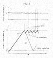
- a characteristic diagrammatic view in Fig. 7 shows an example of a change with time of an estimated trapping amount H and an exhaust gas temperature T according to a comparative example.
- the regeneration restart process which will be described later is executed.
- the regeneration restart process even if the regeneration treatment terminates (is interrupted) along the way since the exhaust gas temperature T is low, the regeneration restart process as the present embodiment is not executed, but the regeneration treatment starts when the estimated trapping amount H is equal to or more than the regeneration start threshold Ht.
- the regeneration treatment of the filter 21 when executed in a case where the construction machine performs a light-load work or there is kept a low rotational state (low idle state) where a rotational number N of the engine 10 is low, the exhaust gas temperature T does not rise sufficiently. Therefore, the regeneration treatment terminates (is interrupted) along the way. The reason for it is that in a case where the exhaust gas temperature T does not rise sufficiently, even if the regeneration treatment continues to be executed, there is a possibility that the particulate matter cannot be sufficiently burned.
- the regeneration treatment is started, and after that, when the exhaust gas temperature T is less than the exhaust gas temperature threshold Ht, the regeneration treatment terminates (is interrupted) along the way.
- the regeneration treatment is started.
- the regeneration operation and the regular operation are alternately repeated by short intervals.
- the rotational number N of the engine 10 is automatically kept to be in a low rotational state (low idle state) by the auto idle control. In this case, when the regeneration treatment is started, there occurs a high possibility of creating the aforementioned problem.
- the controller 27 determines whether or not the regeneration treatment of the filter 21 is interrupted using the exhaust gas temperature T, and besides, determines whether or not the interrupted regeneration treatment is restarted. That is, the controller 27 determines to interrupt the regeneration treatment of the filter 21 when the exhaust gas temperature T becomes less than the exhaust gas temperature threshold Tt in the middle of executing the regeneration treatment of the filter 21 (regeneration interruption determining unit). In addition thereto, the controller 27 determines to restart the regeneration treatment of the filter 21 when the exhaust gas temperature T becomes equal to or more than the exhaust gas temperature threshold Tt in a case where the regeneration treatment of the filter 21 is interrupted (regeneration restart determining unit).
- the regeneration treatment including the determination on the interruption and the determination on the restart of such regeneration treatment will be described later with reference to Fig. 4 and Fig. 5 .
- the regeneration treatment can be restarted to accelerate the burning and the removal of the particulate matter trapped in the filter 21. Therefore, it is possible to suppress that the regeneration operation and the regular operation are alternately repeated by short intervals for a long period of time as shown in the solid characteristic line 32 in Fig. 7 .
- the second regeneration terminated threshold He2 as a threshold of the estimated trapping amount H in a case of terminating the restarted regeneration treatment is set to be larger than the first regeneration terminated threshold Hel as a threshold of the estimated trapping amount H in a case where the regeneration treatment normally terminates without the interruption of the regeneration treatment. Therefore, even in a case where the exhaust gas temperature T tends to be difficult in rising due to the continuation of the light-load work or the low rotational state, it is possible to suppress the restarted regeneration treatment from excessively continuing (the regeneration time from being longer).
- the hydraulic excavator 1 according to the first embodiment has the configuration as described above, and, next, an operation thereof will be explained.
- An operator of the hydraulic excavator 1 gets on the cab 8 of the upper revolving structure 4, and starts the engine 10 to drive the hydraulic pump 15. Thereby, pressurized oil from the hydraulic pump 15 is delivered through control valves to various actuators.
- the lower traveling structure 2 can go forward or backward.
- the working mechanism 5 can be tilted to perform an excavating work of sand and earth or the like.
- the compact hydraulic excavator 1 can perform a ditch excavating work while revolving the upper revolving structure 4 even in a narrow working site such as an urban area, for example.
- the particulate matter that is harmful substances is discharged from the exhaust pipe 12.
- the exhaust gas purifying device 18 can oxidize and remove hydrocarbon (HC), nitrogen oxides (NOx), and carbon monoxides (CO) in an exhaust gas by the oxidation catalyst 20.
- the filter 21 traps the particulate matter contained in the exhaust gas.
- the purified exhaust gas can be discharged through the downstream outlet port 19A to an outside. Further, the trapped particulate matter is burned and removed by the regeneration device 22 to regenerate the filter 21.
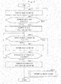
- each in Fig. 4 and Fig. 5 is repeatedly executed every predetermined time (by a predetermined sampling frequency) by the controller 27 while supplying power to the controller 27.
- Step 1 estimation of the trapping amount of particulate matter is made.
- the estimation of this trapping amount can be made by at least one of the following (a) or (b).
- the first estimated trapping amount H1 in the above (a) can be estimated using the first map and the calculation formula stored in the memory 27A in the controller 27. That is, a discharge amount per unit time is found using the aforementioned first map from the engine rotational number N and the fuel injection quantity F, and a total discharge amount Hm from the operating start to the present point is found by integrating the discharge amounts. Specifically, the first estimated trapping amount H1 at the present point can be estimated by subtracting a regeneration amount J of particulate matter that has been removed by the regeneration treatment until the present point from the total discharge amount Hm based upon the aforementioned formula 1. It should be noted that the engine rotational number N is read in from the rotational sensor 23.
- the fuel injection quantity F can be found by, for example, an intake air quantity detected from the air flow meter (not shown) that is provided in the intake side of the engine 10 and an engine rotational number N. Further, the fuel injection quantity F can also be calculated from, for example, a control signal (fuel injection command) that is output to the fuel injection device 14 from the controller 27.
- the exhaust gas temperature T is read in from the exhaust gas temperature sensor 26.
- the second estimated trapping amount H2 in the above (b) can be estimated using the aforementioned second map stored in the memory 27A in the controller 27. That is, the second estimated trapping amount H2 at this point can be estimated based upon the second map of associating a differential pressure ⁇ P, an exhaust gas flow amount and an estimated trapping amount H.
- the differential pressure ⁇ P can be calculated using the aforementioned formula 2 from the pressure P1 in the upstream side of the filter 21 read in by the pressure sensor 24 and the pressure P2 in the downstream side of the filter 21 read in by the pressure sensor 25.
- step 2 it is determined whether or not the automatic regeneration treatment is executed. Specifically, it is determined whether or not the automatic regeneration treatment is executed depending upon whether or not the estimated trapping amount H is equal to or more than the preset regeneration start threshold Ht, for example.
- the determination is made as "NO", that is, it is determined that the estimated trapping amount H is smaller than the preset regeneration start threshold Ht, it is estimated that the particulate matter is not trapped in the filter 21 to the extent that the regeneration treatment is necessary for the filter 21 (the filter 21 is not clogged). In this case, the process goes back to a state before step 1, and the process from step 1 is repeated.
- the process goes to step 3.
- the regeneration treatment of the filter 21 is started. That is, at step 3, a control signal of performing the post injection is output to the fuel injection device 14 from the controller 27. This post injection rises the exhaust gas temperature T from the engine 10 to burn the particulate matter trapped in the filter 21 for removal.
- step 4 it is determined whether or not the regeneration treatment is interrupted based upon the exhaust gas temperature T. That is, when the regeneration treatment continues to be executed in a state where the exhaust gas temperature T is kept to be low, the fuel consumption quantity increases due to the post injection, but there is a possibility that the burning and removal of the particulate matter does not progress. Therefore, at step 4, it is determined whether or not the exhaust gas temperature T is equal to or more than the exhaust gas temperature threshold Tt.
- the exhaust gas temperature T is read in from the exhaust gas temperature sensor 26.
- step 4 the determination is made as "YES", that is, it is determined that the exhaust gas temperature T is equal to or more than the exhaust gas temperature threshold Tt, the process goes to step 5.
- step 5 as similar to the aforementioned step 1, the estimation of the trapping amount of the particulate matter is made.
- step 6 it is determined whether or not the automatic regeneration treatment terminates based upon the estimated trapping amount found at step 5. That is, at step 6, it is determined whether or not the regeneration treatment terminates depending upon whether or not the estimated trapping amount H is equal to or less than a preset first regeneration terminated threshold He1.
- step 6 the determination is made as "NO", that is, it is determined that the estimated trapping amount H is larger than the first regeneration terminated threshold He1, it is estimated that the amount of the particulate matter burned and removed by the regeneration treatment is not still sufficient, in other words, the amount of the particulate matter remaining in the filter 21 is large. In this case, the process goes back to a state before step 4, and the process from step 4 is repeated.
- step 6 the determination is made as "YES", that is, it is determined that the estimated trapping amount H is equal to or less than the first regeneration terminated threshold He1, it is estimated that the particulate matter in the filter 21 is sufficiently burned and removed by the regeneration treatment.
- the process goes to step 7.
- the regeneration treatment terminates . That is, at step 7, a control signal of terminating the post injection is output to the fuel injection device 14 from the controller 27. As a result, the regeneration treatment terminates, the process goes back to Start through Return, and the process from step 1 is repeated.
- step 4 the determination is made as "NO", that is, it is determined that the exhaust gas temperature T is less than the exhaust gas temperature threshold Tt, the process goes to a regeneration interruption restart process of step 8.
- the exhaust gas temperature T is low, and even if the regeneration treatment continues to be executed as it is, it is estimated that the sufficient burning of the particulate matter is not expected. Therefore, the process goes to step 8 to perform the interruption of the regeneration treatment and the restart thereafter.
- the regeneration interruption restart process of step 8 is composed of step 11 to step 17 shown in Fig. 5 . That is, at step 11, the regeneration treatment is interrupted since the exhaust gas temperature T is less than the exhaust gas temperature threshold Tt. Specifically, a control signal of interrupting (temporarily terminating) the post injection is output to the fuel injection device 14 from the controller 27. As a result, the regeneration treatment is interrupted.
- step 12 it is determined whether or not the regeneration treatment is restarted based upon the exhaust gas temperature T. That is, when the regeneration treatment is restarted at a point where the exhaust gas temperature T is high, it is possible to accelerate the burning and removal of the particulate matter trapped in the filter 21. Therefore, at step 12, it is determined whether or not the exhaust gas temperature T is equal to or more than the exhaust gas temperature threshold Tt.
- step 12 the determination is made as "NO", that is, it is determined that the exhaust gas temperature T is less than the exhaust gas temperature threshold Tt, even if the regeneration treatment of the filter 21 is restarted, since the sufficient burning of the particulate matter is not expected, the process waits at step 12 (the process of step 12 is repeated) .
- step 12 the determination is made as "YES", that is, it is determined that the exhaust gas temperature T is equal to or more than the exhaust gas temperature threshold Tt, the process goes to step 13, wherein the regeneration treatment is restarted. That is, at step 13, a control signal of performing the post injection is output to the fuel injection device 14 from the controller 27. This post injection burns the particulate matter accumulated in the filter 21 for removal.
- step 14 it is determined whether or not the regeneration treatment is interrupted based upon the exhaust gas temperature T. That is, when the restarted regeneration treatment continues to be executed in a state where the exhaust gas temperature T is kept to be low, the fuel consumption quantity increases due to the post injection, but there is a possibility that the burning and removal of the particulate matter does not progress. Therefore, at step 14, as similar to the aforementioned step 12, it is determined whether or not the exhaust gas temperature T is equal to or more than the exhaust gas temperature threshold Tt.
- step 14 the determination is made as "YES", that is, it is determined that the exhaust gas temperature T is equal to or more than the exhaust gas temperature threshold Tt, the process goes to step 15.
- step 15 as similar to the aforementioned step 1 and step 5, the estimation of the trapping amount of the particulate matter is made.
- step 16 it is determined whether or not the restarted regeneration treatment terminates based upon the estimated trapping amount H found at step 15. That is, at step 16, it is determined whether or not the restarted regeneration treatment terminates depending upon whether or not the estimated trapping amount H is equal to or less than a preset second regeneration terminated threshold He2.
- the determination is made as "NO", that is, it is determined that the estimated trapping amount H is larger than the second regeneration terminated threshold He2, it is estimated that the amount of the particulate matter burned and removed by the regeneration treatment is not still sufficient, in other words, the amount of the particulate matter remaining in the filter 21 is still large. In this case, the process goes back to a state before step 14, and the process from step 14 is repeated.
- the determination is made as "YES", that is, it is determined that the estimated trapping amount H is equal to or less than the second regeneration terminated threshold He2, it is estimated that the amount of the particulate matter in the filter 21 is sufficiently burned and removed by the restarted regeneration treatment.
- the process goes to step 17.
- the regeneration treatment terminates as similar to the aforementioned step 7. That is, at step 17, a control signal of terminating the post injection is output to the fuel injection device 14 from the controller 27. As a result, the regeneration treatment terminates, the process goes back to Start through Return in Fig. 5 and Return in Fig. 4 , and the process from step 1 is repeated.
- step 14 the determination is made as "NO", that is, it is determined that the exhaust gas temperature T is less than the exhaust gas temperature threshold Tt, the process goes back to a state before step 11. That is, since the exhaust gas temperature T is equal to or more than the exhaust gas temperature threshold Tt, the regeneration treatment is restarted, but thereafter, the exhaust gas temperature T becomes less than the exhaust gas temperature threshold Tt, and even if the restarted regeneration treatment continues to be executed, it is estimated that the sufficient burning of the particulate matter is not expected. Therefore, the process goes back to a state before step 11 to repeat the process from step 11 (processes of interruption and restart of the regeneration treatment).
- the exhaust gas temperature T becomes less than the exhaust gas temperature threshold Tt during a period of executing the regeneration treatment of the filter 21, at the process of step 4, it is determined to interrupt the regeneration treatment of the filter 21, and at the process of the subsequent step 8, more specifically, at the process of step 11, the regeneration treatment of the filter 21 is interrupted.
- the exhaust gas temperature T is low, and when the sufficient burning of the particulate matter is not expected, at the process of step 4 and at the process of the subsequent step 11, the regeneration treatment of the filter 21 is interrupted.
- the next regeneration treatment is started not when the estimated trapping amount H of the particulate matter in the filter 21 is equal to or more than the regeneration start threshold Ht, but when the exhaust gas temperature T is equal to or more than the exhaust gas temperature Threshold Tt. That is, even in a case where the exhaust gas temperature T is low to interrupt the regeneration treatment, when the exhaust gas temperature T is equal to or more than the exhaust gas temperature threshold Tt, at the process of step 12 and at the process of the subsequent step 13, the regeneration treatment is restarted.
- the regeneration treatment is interrupted due to the lowering of the exhaust gas temperature T, when, at the process of step 12 and at the process of the subsequent step 13, the regeneration treatment is restarted, as shown in the characteristic line 33 in Fig. 6 , it is possible to accelerate the burning and removal of the particulate matter trapped in the filter 21.
- whether or not the regeneration treatment restarted at the process of step 12 and at the process of the subsequent step 13 terminates is determined based upon the process of step 16, that is, the estimated trapping amount H is equal to or less than the second regeneration terminated threshold He2.
- the determination is not made as "NO" that is, the regeneration treatment advances without the interruption of the regeneration treatment
- whether or not the regeneration treatment terminates is determined based upon the process of step 6, that is, whether or not the estimated trapping amount H is equal to or less than the first regeneration terminated threshold He1.
- the second regeneration terminated threshold (restart terminated value) He2 is set between the regeneration start threshold (regeneration start value) Ht and the first regeneration terminated threshold (normal terminated value) He1.
- the second regeneration terminated threshold He2 is set to a value larger than the first regeneration terminated threshold He1 and smaller than the regeneration start threshold Ht. Therefore, even if the exhaust gas temperature T tends to be difficult to rise due to the continuation of the light-load work or low rotational state, it is possible to suppress the regeneration treatment restarted at the process of step 12 and at the process of the subsequent step 13 from excessively continuing (the regeneration treatment from being longer) .
- the restarted regeneration treatment can terminate earlier. As a result, it is possible to suppress uncomfortable feelings from being given to an operator from this point of view as well.
- the processes at step 1 and step 5 in Fig. 4 , and at step 15 in Fig. 5 show a specific example of the PM calculating unit that is an element of the present invention, and the process at step 2 in Fig. 4 shows a specific example of the regeneration start determining unit.
- the process at step 4 in Fig. 4 and the process at step 14 in Fig. 5 show a specific example of the regeneration interruption determining unit that is an element of the present invention, and the process at step 12 in Fig. 5 shows a specific example of the regeneration restart determining unit.
- the process at step 6 in Fig. 4 and the process at step 16 in Fig. 5 correspond to a specific example of the regeneration termination determining unit.
- Fig. 8 shows a second embodiment in the present invention.
- the second embodiment is characterized by executing regeneration treatment, not by performing the post injection, but by driving at least one of an intake throttle valve provided in an intake side of an engine and an exhaust throttle valve provided in an exhaust side thereof in a direction of throttling a flow passage thereof.
- components identical to those in the aforementioned first embodiment are referred to as identical reference numerals, and an explanation thereof is omitted.
- the regeneration device 41 for executing the regeneration treatment of the filter 21 by burning the particulate matter trapped in the filter 21.
- the regeneration device 41 includes the fuel injection device 14, an intake throttle valve 42, an exhaust throttle valve 43, the rotational sensor 23, the pressure sensors 24 and 25, the exhaust gas temperature sensor 26, and the controller 27.
- the regeneration device 41 at the time of executing the regeneration treatment, drives at least one of the intake throttle valve 42 and the exhaust throttle valve 43 in the direction of throttling the flow passage thereof to burn and remove the particulate matter accumulated in the filter 21.
- the intake throttle valve 42 is provided in the intake pipe 11 side of the engine 10, and forms part of the regeneration device 41 for executing the regeneration treatment of the filter 21.
- the intake throttle valve 42 is regularly held in an opened state in response to a control signal from the controller 27 (for example, in an opening degree corresponding to a fuel injection quantity F or in a fully opened state) .
- the intake throttle valve 42 is driven in the direction of throttling the flow passage by the control signal from the controller 27.
- the intake throttle valve 42 throttles an intake air quantity such that an air-fuel ratio of air and fuel becomes in a richer side.
- a temperature of an exhaust gas discharged to the exhaust pipe 12 side rises in a combustion chamber in the engine 10 by burning the fuel the air-fuel ratio of which has become in the richer side, thus making it possible to burn and remove the particulate matter trapped in the filter 21.
- the exhaust throttle valve 43 is provided in the exhaust pipe 12 side of the engine 10, and the exhaust throttle valve 43 also forms part of the regeneration device 41 for executing the regeneration treatment of the filter 21.
- the exhaust throttle valve 43 is regularly held in a fully opened state in response to a control signal from the controller 27.
- the exhaust throttle valve 43 is driven in the direction of throttling the flow passage in response to the control signal from the controller 27 to perform control of throttling the opening degree to be smaller.
- the exhaust throttle valve 43 throttles a flow amount of an exhaust gas flowing in the exhaust pipe 12 to apply a back pressure to the engine 10 and increase loads to the engine 10.
- the controller 27 increases a fuel injection quantity F by the fuel injection device 14 of the engine 10 corresponding to the above-mentioned load. As a result, a temperature of the exhaust gas rises, thereby making it possible to burn and remove the particulate matter trapped in the filter 21.
- the second embodiment executes the regeneration treatment by driving at least one of the intake throttle valve 42 and the exhaust throttle valve 43 in the direction of throttling the flow passage as describe above, and does not particularly differ in the basic function from the aforementioned first embodiment.
- the regeneration treatment since the regeneration treatment is executed by driving at least one of the intake throttle valve 42 and the exhaust throttle valve 43 in the direction of throttling the flow passage, the regeneration treatment can be executed at a lower temperature as compared to a case of executing the regeneration treatment by the post injection. Thereby, durability of the filter 21 can be improved.
- the first estimated trapping amount H1 is estimated based upon an engine rotational number N, a fuel injection quantity F and an exhaust gas temperature T as an example.
- the present invention is not limited thereto, and, for example, the first estimated trapping amount H1 may be estimated based upon not only an engine rotational number N, a fuel injection quantity F and an exhaust gas temperature T, but also a temperature of each of components such as a filter, a state amount such as an engine load (state amount representative of an operating condition) and the like.
- the exhaust gas purifying device 18 is configured by the oxidation catalyst 20 and the filter 21 as an example.
- the present invention is not limited thereto, and may be configured, for example, by combining a urea injection valve, a selective reduction catalyst device and the like in addition to the oxidation catalyst and the particulate matter removing filter.
- each of the aforementioned embodiments is explained by taking a case where the exhaust gas purifying device 18 is mounted on the compact hydraulic excavator 1 as an example.
- the construction machine provided with the exhaust gas purifying device by the present invention is not limited thereto, but may be applied to a middle-sized or larger-sized hydraulic excavator.
- the exhaust gas purifying device 18 may widely be applied also to a construction machine such as a hydraulic excavator which is provided with a wheel type lower traveling structure, a wheel loader, a fork lift, and a hydraulic crane, and the like.
Description
- The present invention relates to a construction machine that is provided with an exhaust gas purifying device suitable for removing harmful substances from an exhaust gas in a diesel engine, for example, or the like.
- In general, a construction machine such as a hydraulic excavator or a hydraulic crane is configured by an automotive lower travelling structure, an upper revolving structure mounted on the lower travelling structure to be capable of revolving thereon, and a working mechanism tiltably mounted on a front side of the upper revolving structure. The upper revolving structure mounts an engine on a rear part in a revolving frame for driving a hydraulic pump, and mounts a cab, a fuel tank, an operating oil tank and the like on a front side in the revolving frame.
- Here, a diesel engine is generally used as an engine that is a prime mover of a construction machine. There are some cases where harmful substances such as particulate matter (PM), nitrogen oxides (NOx) and the like are contained in an exhaust gas discharged from such a diesel engine. Therefore, the construction machine is provided with an exhaust gas purifying device in an exhaust pipe forming an exhaust gas passage of the engine for purifying an exhaust gas therein.
- The exhaust gas purifying device is configured by an oxidation catalyst (for example, diesel oxidation catalyst, referred to as "DOC" for short) for oxidizing and removing nitrogen monoxides (NO), carbon monoxides (CO), hydrocarbon (HC) and the like that are contained in an exhaust gas, and a particulate matter removing filter (for example, diesel particulate filter, referred to as "DPF" for short) that is arranged downstream side of the oxidation catalyst for trapping and removing particulate matter in the exhaust gas (Patent Document 1).
- Incidentally, in the particulate matter removing filter, the particulate matter is accumulated therein following the trapping of the particulate matter, which might cause the filter to be clogged. Therefore, it is necessary to remove the particulate matter from the filter in a point where a predetermined amount of the particulate matter is trapped for regenerating the filter. This regeneration treatment of the filter can be performed in such a manner that fuel injection for regeneration treatment called "post injection" is performed to increase a temperature of an exhaust gas for burning the particulate matter that is accumulated in the filter.
- On the other hand, in case the regeneration treatment of the filter is executed in a point where the particulate matter is excessively accumulated in the filter (excessive accumulation), the temperature of the exhaust gas rises to be excessively high (a burning temperature of the particulate matter is excessively high), which might possibly cause the filter to be melted and damaged. Therefore, the conventional art is configured such that a trapping amount of the particulate matter trapped in the filter is estimated (calculated) and the regeneration treatment is automatically executed before the estimated trapping amount becomes excessively large, that is, when the estimated trapping amount reaches a predetermined threshold (Patent Document 2).
-
- Patent Document 1: Japanese Patent Laid-Open No.
2010-65577 A - Patent Document 2: Japanese Patent Laid-Open No.
2000-161044 A - Patent document 3:
US2006168939 - Incidentally, in a case where the regeneration treatment of the filter is executed, for example, when the construction machine performs a light-load work or when the construction machine is kept in a low rotational state (low idle state) where a rotational number (rotational speed) of an engine is low (on standby), a temperature of an exhaust gas does not rise sufficiently. Therefore, even if the regeneration treatment continues to be executed, there is a possibility that the particulate matter cannot be sufficiently burned and removed. Accordingly, it is preferable that the regeneration treatment automatically terminates when the temperature of the exhaust gas is low. However, in a case of simply terminating the regeneration treatment, the regeneration treatment terminates in a state where the particulate matter burns slightly. As a result, in a case where the light-load work or the standby in the state of the low rotational state of the engine is kept, the regeneration operation and the regular operation are possibly alternately repeated by short intervals.
- This repetition possibly leads to, for example, an increase in fuel consumption quantity with an increase of post injections, excessive accumulation of particulate matter due to insufficient burning of the particulate matter and deterioration of working conditions by the exhaust gas. In addition to this, uncomfortable feelings are possibly given to an operator following a change in engine sounds at the time of switching the regular operation and the regeneration operation. Further, there is a possibility that fuel having adhered to a cylinder inner wall of an engine due to the post injection falls down into an oil pan, the fuel is then mixed with engine oil, leading to dilution of the engine oil (oil dilution).
- The present invention is made in view of a problem of the foregoing conventional art, and an object of the present invention is to provide a construction machine that can suppress a regeneration operation and a regular operation from being alternately repeated by short intervals.
- (1) A construction machine according to the present invention comprises a vehicle body; an engine that is mounted on the vehicle body and is driven by injection of fuel; an exhaust gas purifying device that is provided in an exhaust side of the engine and includes a filter for trapping particulate matter in an exhaust gas discharged from the engine; and a regeneration device that burns the particulate matter trapped in the filter in the exhaust gas purifying device to execute regeneration treatment of the filter.
In order to solve the above-described problems, a characteristic of a configuration adopted by the present invention is that the regeneration device comprises: a temperature detector that detects a temperature of an exhaust gas discharged from the engine; a PM calculating unit that estimates a trapping amount of the particulate matter trapped in the filter; a regeneration start determining unit that determines to start the regeneration treatment of the filter when the estimated trapping amount estimated by the PM calculating unit is equal to or more than a preset regeneration start value; a regeneration interruption determining unit that determines to interrupt the regeneration treatment of the filter when the exhaust gas temperature detected by the temperature detector becomes less than a preset given temperature in the middle of executing the regeneration treatment of the filter; and a regeneration restart determining unit that determines to restart the regeneration treatment of the filter when the exhaust gas temperature becomes equal to or more than the preset given temperature in a case where the regeneration treatment of the filter is interrupted based upon the determination of the regeneration interruption determining unit.
With this arrangement, when the exhaust gas temperature detected by the temperature detector becomes less than the preset given temperature in the middle of executing the regeneration treatment of the filter, the regeneration treatment of the filter is interrupted based upon the determination of the regeneration interruption determining unit. Therefore, when the exhaust gas temperature is low and the sufficient burning of the particulate matter is not expected, the regeneration treatment of the filter is interrupted based upon the determination of the regeneration interruption determining unit. As a result, it is possible to suppress an increase in fuel consumption quantity and dilution of the engine oil due to the mixing of the fuel with the engine oil.
On the other hand, when the regeneration treatment of the filter is interrupted based upon the determination of the regeneration interruption determining unit, the next regeneration treatment is started not on a condition that the estimated trapping amount of the particulate matter in the filter is equal to or more than the regeneration start value, but on a condition that the exhaust gas temperature is equal to or more than the given temperature. That is, even in a case where the exhaust gas temperature is lowered and the generation treatment is interrupted, when the exhaust gas temperature is equal to or more than the given temperature after that, the regeneration treatment of the filter is restarted based upon the determination of the regeneration restart determining unit.
Therefore, it is possible to suppress that the regular operation continues to be performed until the estimated trapping amount becomes equal to or more than the preset regeneration start value. In other words, even when the exhaust gas temperature is lowered to interrupt the regeneration treatment, it is possible to accelerate the burning and removal of the particulate matter trapped in the filter by restarting the regeneration treatment based upon the determination of the regeneration restart determining unit.
Thereby, alternate repetition of the regeneration operation and the regular operation by short intervals can be suppressed, thus preventing deterioration of the working conditions, as well as an operator from being subjected to uncomfortable feelings. In addition thereto, it is possible to realize a reduction in fuel consumption quantity (low fuel consumption), suppression of excessive accumulation of particulate matter and suppression of oil dilution to improve the regeneration device, and finally stability and reliability of the construction machine. - (2) According to the present invention, when the estimated trapping amount estimated by the PM calculating unit is defined as a normal terminated value in a case where the regeneration treatment of the filter normally terminates without the interruption, and when the estimated trapping amount estimated by the PM calculating unit is defined as a restart terminated value in a case of terminating the regeneration treatment restarted based upon the determination of the regeneration restart determining unit, the restart terminated value is set between the regeneration start value and the normal terminated value.
- With this arrangement, the restart terminated value is set between the regeneration start value and the normal terminated value. In other words, the restart terminated value as a threshold of the estimated trapping amount in a case of terminating the restarted regeneration treatment is set to be larger than the normal terminated value as a threshold of the estimated trapping amount in a case where the regeneration treatment normally terminates without the interruption. Therefore, even in a case where the exhaust gas temperature tends to be difficult in rising due to the continuation of the light-load work or the standby (neglect) in the low rotational state, it is possible to suppress the regeneration treatment restarted based upon the determination of the regeneration restart determining unit from excessively continuing (the regeneration time from being longer).
-
-
Fig. 1 is a front view showing a hydraulic excavator that is applied to a first embodiment of the present invention. -
Fig. 2 is a partial cutaway plan view in which the hydraulic excavator is enlarged in a state where a cab and an exterior cover are partially removed from an upper revolving structure inFig. 1 . -
Fig. 3 is a circuit configuration diagram showing an engine, an exhaust gas purifying device, a regeneration device, and the like. -
Fig. 4 is a flow chart showing regeneration treatment of a filter by the regeneration device. -
Fig. 5 is a flow chart showing an interruption restart process bystep 8 inFig. 4 . -
Fig. 6 is a characteristic line diagram showing an example of a change with time of an estimated trapping amount and an exhaust gas temperature according to the first embodiment. -
Fig. 7 is a characteristic line diagram showing an example of a change with time of an estimated trapping amount and an exhaust gas temperature according to a comparative example. -
Fig. 8 is a circuit configuration diagram showing an engine, an exhaust gas purifying device, a regeneration device, and the like according to a second embodiment of the present invention. - Hereinafter, embodiments of a construction machine according to the present invention will be in detail explained referring to the accompanying drawings by taking a case where the construction machine is applied to a compact hydraulic excavator called "mini excavator" as an example.
-
Fig. 1 to Fig. 6 show a first embodiment of the present invention. - In the figure, designated at 1 is a compact hydraulic excavator used for an excavating work of sand and earth or the like. This
hydraulic excavator 1 is typically called a mini excavator. Thehydraulic excavator 1 includes a crawler type of automotivelower traveling structure 2, an upper revolvingstructure 4 that is mounted through a revolvingdevice 3 on thelower traveling structure 2 to be capable of revolving thereon and configures a vehicle body together with thelower traveling structure 2, and aworking mechanism 5 that is tiltably provided in a front side of the upper revolvingstructure 4. - Here, the
working mechanism 5 is configured as a swing post type working mechanism, and is provided with, for example, aswing post 5A, aboom 5B, anarm 5C, abucket 5D as a working tool, aswing cylinder 5E (refer toFig. 2 ) for swinging theworking mechanism 5 in the left-right direction, aboom cylinder 5F, anarm cylinder 5G, and abucket cylinder 5H. The upper revolvingstructure 4 includes a revolvingframe 6, anexterior cover 7, acab 8, and acounterweight 9, which will be described later. - The revolving
frame 6 forms part of a structure of the upper revolvingstructure 4. The revolvingframe 6 is mounted through the revolvingdevice 3 on thelower traveling structure 2. The revolvingframe 6 is provided with thecounterweight 9 and theengine 10 in the rear part side, which will be described later, thecab 8 in the left front side which will be described later, and afuel tank 16 in the right front side which will be described later. The revolvingframe 6 is provided with theexterior cover 7 that is positioned from the right side to the rear side of thecab 8. Thisexterior cover 7 defines therein a space that accommodates theengine 10, ahydraulic pump 15, aheat exchanger 17, an exhaust gas purifyingdevice 18 and the like, together with the revolvingframe 6, thecab 8 and thecounterweight 9. - The
cab 8 is mounted in the left front side of the revolvingframe 6, and thecab 8 defines therein an operator's room in which an operator gets. An operator's seat on which the operator is seated, various operational levers and the like (any thereof is not shown) are disposed inside thecab 8. - The
counterweight 9 acts as a weight balance to the workingmechanism 5. Thecounterweight 9 is mounted at the rear end part of the revolvingframe 6 to be positioned in the rear side of theengine 10 which will be described later. As shown inFig. 2 , thecounterweight 9 is formed in a circular shape on the rear surface side. Thecounterweight 9 is configured to be accommodated within a vehicle width of thelower traveling structure 2. - Indicated at 10 is the engine mounted in the rear side of the revolving
frame 6 in a transversely placed state. Theengine 10 is mounted on the compacthydraulic excavator 1 as a prime mover, and is therefore configured by a compact diesel engine, for example. Theengine 10 is provided with anintake pipe 11 for taking in outside air (refer toFig. 3 ) and anexhaust pipe 12 forming a part of an exhaust gas passage for discharging an exhaust gas. Outside air flows into theintake pipe 11 toward theengine 10, and anair cleaner 13 is connected to theintake pipe 11 in a tip end side for purifying the outside air. The exhaustgas purifying device 18 which will be described later is provided to be connected to theexhaust pipe 12. - Here, the
engine 10 is driven by injection of fuel. Specifically, theengine 10 is configured by an electronically controlled engine, and a supply quantity of fuel thereto is variably controlled by a fuel injection device 14 (refer toFig. 3 ) including an electronically controlled injection valve. That is, thefuel injection device 14 variably controls an injection quantity of fuel injected into a cylinder (not shown) of theengine 10 based upon a control signal that is output from acontroller 27 which will be described later. - Further, the
fuel injection device 14 configures part of aregeneration device 22 together with thecontroller 27 which will be described later and the like (refer toFig. 3 ). Thefuel injection device 14 performs fuel injection for regeneration treatment, for example, called "post injection" (additional injection after combustion process) in response to a control signal from thecontroller 27. This post injection increases a temperature of an exhaust gas to burn and remove particulate matter accumulated in a particulatematter removing filter 21 in the exhaustgas purifying device 18 which will be described later. - The
hydraulic pump 15 is mounted to the left side of theengine 10. Thehydraulic pump 15 forms part of a hydraulic source together with an operating oil tank (not shown). Thehydraulic pump 15 is driven by theengine 10 to eject pressurized oil (operating oil) toward a control valve (not shown). Thehydraulic pump 15 is configured by, for example, a swash plate type, bent axis type or radial piston type hydraulic pump of a variable displacement type. It should be noted that thehydraulic pump 15 is not necessarily limited to the hydraulic pump of a variable displacement type, but may be configured by using a hydraulic pump of a fixed displacement type. - The
fuel tank 16 is provided on the revolvingframe 6 to be positioned to the right side of thecab 8, and is covered with theexterior cover 7 together with the unshown operating oil tank and the like. Thefuel tank 16 is formed, for example, as a cubic pressure tight tank and reserves therein fuel to be supplied to theengine 10. - The
heat exchanger 17 is provided on the revolvingframe 6 to be positioned to the right side of theengine 10. Theheat exchanger 17 is configured by, for example, a radiator, an oil cooler, and an intercooler. That is, theheat exchanger 17 cools cooling water of theengine 10, as well as pressurized oil that is returned back to the operating oil tank. - Next, the exhaust
gas purifying device 18 for purifying an exhaust gas discharged from theengine 10 will be explained. - That is, designated at 18 is the exhaust gas purifying device that is provided in the exhaust side of the
engine 10. As shown inFig. 2 , the exhaustgas purifying device 18 is arranged in the upper part left side of theengine 10 in a position above thehydraulic pump 15, for example, and is connected at the upstream side to theexhaust pipe 12 of theengine 10. The exhaustgas purifying device 18 forms part of an exhaust gas passage together with theexhaust pipe 12 and removes harmful substances contained in an exhaust gas during a period where the exhaust gas flows from the upstream side to the downstream side therein. - That is, the
engine 10 comprising the diesel engine has a high efficiency and is excellent in durability, but harmful substances such as particulate matter (PM), nitrogen oxides (NOx), and carbon monoxides (CO) and the like are contained in the exhaust gas from theengine 10. Therefore, as shown inFig. 3 , the exhaustgas purifying device 18 mounted on theexhaust pipe 12 is configured by anoxidation catalyst 20 for oxidizing and removing carbon monoxides (CO) or the like in the exhaust gas and the particulatematter removing filter 21, which will be described later, for trapping and removing the particulate matter (PM) in the exhaust gas. - As shown in
Fig. 3 , the exhaustgas purifying device 18 is provided with acylindrical casing 19 configured by removably connecting a plurality of cylinders in the front and rear direction, for example. Theoxidation catalyst 20 called "DOC" and the particulatematter removing filter 21 called "DPF" (hereinafter called "filter 21") are removably accommodated in thecasing 19. Anoutlet port 19A is connected to an outlet side of thecasing 19 to be positioned downstream of thefilter 21. Thisoutlet port 19A is configured by, for example, a chimney for releasing the purified exhaust gas into an atmosphere, and a muffling device. - The
oxidation catalyst 20 comprises a cell-shaped cylindrical body made of ceramic having an outer diameter dimension that is equivalent to an inner diameter dimension of thecasing 19, for example. Many through holes (not shown) are axially formed in theoxidation catalyst 20, an inner surface of which is coated with noble metals. Theoxidation catalyst 20 oxidizes and removes carbon monoxides (CO), hydrocarbon (HC), and the like contained in the exhaust gas by circulating the exhaust gas into each through hole under a predetermined temperature condition, and, for example, removes nitrogen monoxide (NO) as nitrogen dioxides (NO2). - On the other hand, the
filter 21 is arranged downstream side of theoxidation catalyst 20 in thecasing 19. Thefilter 21 traps particulate matter in the exhaust gas discharged from theengine 10, and burns and removes the trapped particulate matter to perform purification of the exhaust gas. Therefore, thefilter 21 is configured by a cell-shaped cylindrical body which is, for example, a porous member made of a ceramic material, having many small bores (not shown) in an axial direction. Thereby, thefilter 21 traps particulate matter through many small bores, and the trapped particulate matter is burned and removed by regeneration treatment of theregeneration device 22 which will be described later. As a result, thefilter 21 is regenerated. - Next, the
regeneration device 22 for executing the regeneration treatment of thefilter 21 will be explained. - That is, denoted at 22 is the regeneration device for executing the regeneration treatment of the
filter 21 by burning the particulate matter trapped in thefilter 21 in the exhaustgas purifying device 18. Theregeneration device 22 includes the aforementionedfuel injection device 14, arotational sensor 23,pressure sensors gas temperature sensor 26, and thecontroller 27, which will be described later. Theregeneration device 22 automatically executes the regeneration treatment based upon the determination of thecontroller 27, that is, not based upon an operation by an operator. Specifically, theregeneration device 22 performs a post injection by thefuel injection device 14 in response to a command signal (control signal) of thecontroller 27. This post injection increases a temperature of an exhaust gas in theexhaust pipe 12 to burn and remove the particulate matter accumulated in thefilter 21. - The
rotational sensor 23 detects a rotational number (rotational speed) N of theengine 10, and therotational sensor 23 detects the rotational number N of theengine 10 and outputs the detection signal to thecontroller 27 which will be described later. Thecontroller 27 estimates a trapping amount of the particulate matter trapped in thefilter 21 based upon an engine rotational number N detected by therotational sensor 23, a fuel injection quantity F injected by thefuel injection device 14, and an exhaust temperature (exhaust gas temperature) T detected by the exhaustgas temperature sensor 26 which will be described later. Further, thecontroller 27 determines whether or not the regeneration treatment is executed based upon a first estimated trapping amount H1 which is the estimated trapping amount. It should be noted that the fuel injection quantity F can be found, for example, from an intake air quantity detected from an unshown air flow meter provided in the intake side of theengine 10 and an engine rotational number N, and besides, can be calculated also from a control signal (fuel injection command) that is output to thefuel injection device 14 from thecontroller 27, for example. - The
pressure sensors casing 19 in the exhaustgas purifying device 18. As shown inFig. 3 , thepressure sensor 24 is arranged at an inlet side (upstream side) of thefilter 21 and thepressure sensor 25 is arranged at an outlet side (downstream side) of thefilter 21, which output the respective detection signals to thecontroller 27 which will be described later. Thecontroller 27 calculates a differential pressure ΔP between a pressure P1 in the inlet side detected by thepressure sensor 24 and a pressure P2 in the outlet side detected by thepressure sensor 25, and estimates a trapping amount of the particulate matter in thefilter 21 based upon the differential pressure ΔP, an exhaust gas temperature T, and an exhaust gas flow amount, and determines whether or not the regeneration treatment is executed based upon a second estimated trapping amount H2 that is the estimated trapping amount. - The exhaust
gas temperature sensor 26 is a temperature detector that detects a temperature (exhaust gas temperature) T of an exhaust gas discharged from theengine 10. As shown inFig. 3 , the exhaustgas temperature sensor 26 is mounted to thecasing 19 in the exhaustgas purifying device 18, and detects a temperature T of an exhaust gas discharged from theexhaust pipe 12 side, for example. The exhaust gas temperature T upstream of thefilter 21 detected by the exhaustgas temperature sensor 26 is output to thecontroller 27, which will be described later, as a detection signal. The exhaust gas temperature T is used for estimation of a trapping amount of the particulate matter trapped in thefilter 21, determination of interruption and the restart of the regeneration treatment, and the like. - The
controller 27 includes a microcomputer, and thecontroller 27 is connected at the input side to thefuel injection device 14, therotational sensor 23, thepressure sensors gas temperature sensor 26, the unshown air flow meter, and the like. Thecontroller 27 is connected at the output side to thefuel injection device 14, and the like. Thecontroller 27 has amemory 27A including a ROM and a RAM. Process programs for regeneration treatment shown inFig. 4 andFig. 5 which will be described later, a first map and a second map in advance produced for estimating a trapping amount of particulate matter, calculation formulas, and besides, as shown inFig. 6 , a preset regeneration start threshold Ht [g/I], a first regeneration terminated threshold He1[g/I], a second regeneration terminated threshold He2[g/I], an exhaust gas temperature threshold Tt[°C] shown inFig. 6 , and the like are stored in thememory 27A. - Here, the first map is a map for finding a discharge amount Hm of particulate matter discharged from the
engine 10 based upon at least a rotational number N of theengine 10 and a fuel injection quantity F. Specifically, the first map is a map that is produced based upon a corresponding relation between an engine rotational number N, a fuel injection quantity F, and a discharge amount Hm of particulate matter, for example which is in advance found by experiments, calculations, simulations and the like. The calculation formula for estimating the trapping amount can be expressed according to the followingformula 1 in a case where a first estimated trapping amount is indicated at H1, a discharge amount of the particulate matter found by the first map is indicated at Hm and an amount (regeneration amount) of particulate matter removed from thefilter 21 by the regeneration treatment is indicated atJ. 
- In this case, the amount of the particulate matter removed from the regeneration treatment, that is, the regeneration amount J can be calculated from, for example, a relation between a flow amount of an exhaust gas found by an engine rotational number N and a fuel injection quantity F, an exhaust gas temperature T, and a NO2 conversion rate found by adding the exhaust gas temperature T to a discharge amount of nitrogen oxides (NOx) found by an engine rotational number N and a fuel injection quantity F.
- On the other hand, the second map is used for estimating a trapping amount of particulate matter based upon a differential pressure ΔP across the
filter 21. Specifically, the second map is a map that is produced based upon, for example, a corresponding relation between the differential pressure ΔP, an exhaust gas flow amount and a second estimated trapping amount H2, which is in advance found by experiments, calculations, simulations, and the like. It should be noted that the flow amount of the exhaust gas can be found, for example, by an engine rotational number N and a fuel injection quantity F. The differential pressure ΔP across thefilter 21 can be calculated according to the followingformula 2 in a case where the pressure in an inlet side detected by thepressure sensor 24 is indicated at P1 and the pressure in an outlet side detected by thepressure sensor 25 is indicated at P2.
- Next, by referring to
Fig. 6 , the regeneration start threshold Ht [g/I] is a threshold (regeneration start value) of an estimated trapping amount H for determining whether or not the regeneration treatment is started. That is, the regeneration start threshold Ht becomes a determination value for determining that the regeneration treatment is necessary when a first estimated trapping amount H1 estimated by the aforementioned first map and the calculation formula and/or a second estimated trapping amount H2 estimated by the aforementioned second map is equal to or more than the regeneration start threshold Ht. In other words, the regeneration start threshold Ht is a determination value for determining whether or not the particulate matter trapped in thefilter 21 becomes a trapping amount necessary for the regeneration treatment of thefilter 21. Therefore, the regeneration start threshold Ht is preliminarily set based upon experiments, calculations, simulations and the like such that the regeneration treatment can be executed in an appropriate state, that is, in a state where the particulate matter is sufficiently trapped in thefilter 21. Thereby, it is possible to stably and automatically execute the regeneration treatment by theregeneration device 22 when the particulate matter is sufficiently trapped in thefilter 21. - On the other hand, the first regeneration terminated threshold He1[g/I] is a threshold (normal terminated value) of an estimated trapping amount H for determining whether or not the regeneration treatment terminates when the regeneration treatment of the
filter 21 is executed without the interruption, which will be described later. That is, the first regeneration terminated threshold He1 is a determination value for determining that the particulate matter in thefilter 21 is sufficiently burned and removed when the first estimated trapping amount H1 estimated by the aforementioned first map and the calculation formula and/or the second estimated trapping amount H2 estimated by the aforementioned second map becomes equal to or less than the first regeneration terminated threshold He1 while the regeneration treatment of thefilter 21 is executed without terminating along the way (without the interruption). In other words, the first regeneration terminated threshold He1 is a determination value for determining whether or not the mount of the particulate matter in thefilter 21 is reduced to a sufficiently low remaining amount in a case where the regeneration treatment of thefilter 21 normally terminates without the interruption. - Here, in case the first regeneration terminated threshold He1 is set to be smaller, the amount of the particulate matter that can be trapped in the
filter 21 until the next regeneration treatment can be increased the more. That is, as the first regeneration terminated threshold He1 is set to be smaller, an interval to the start of the next regeneration treatment can be made the longer. Therefore, the first regeneration terminated threshold He1 is preliminarily set based upon experiments, calculations, simulations and the like such that the normal regeneration treatment without the interruption can terminate in an appropriate state (in an appropriate remaining amount). - On the other hand, the second regeneration terminated threshold He2[g/I] is a threshold (restart terminated value) of an estimated trapping amount H for determining whether or not the restarted regeneration treatment terminates when the regeneration treatment of the
filter 21 is interrupted and thereafter is restarted. That is, the second regeneration terminated threshold He2 is a determination value for determining to terminate the restarted regeneration treatment when the first estimated trapping amount H1 estimated by the aforementioned first map and the calculation formula and/or the second estimated trapping amount H2 estimated by the aforementioned second map becomes equal to or less than the second regeneration terminated threshold He2 in a case where the regeneration treatment of thefilter 21 is interrupted and thereafter is restarted. In other words, the second regeneration terminated threshold He2 is a determination value for determining whether or not the amount of the particulate matter in thefilter 21 is reduced to a desired remaining amount in a case of terminating the restarted regeneration treatment. - Here, as similar to the first regeneration terminated threshold He1, in case the second regeneration terminated threshold He2 also is set to be smaller, the amount of the particulate matter that can be trapped in the
filter 21 until the next regeneration treatment can be increased the more. That is, in case the second regeneration terminated threshold He2 is set to be smaller, an interval to the start of the next regeneration treatment can be made the longer. However, as the second regeneration terminated threshold He2 is set to be small (for example, is set to the same value as the first regeneration terminated threshold He1), the restarted regeneration treatment possibly continues to be excessively executed (the regeneration treatment time becomes longer). - Therefore, in the present embodiment, the second regeneration terminated threshold (restart terminated value) He2 is set to a value between the regeneration start threshold (regeneration start value) Ht and the first regeneration terminated threshold (normal terminated value) He1. In other words, the second regeneration terminated threshold He2 is set to a value larger than the first regeneration terminated threshold He1 and smaller than the regeneration start threshold Ht. The second regeneration terminated threshold He2 also is preliminarily set based upon experiments, calculations, simulations and the like such that the restarted regeneration treatment can terminate in an appropriate state (the regeneration time does not become excessively long).
- The exhaust gas temperature threshold Tt is a threshold of an exhaust gas temperature T for determining whether or not the regeneration treatment is interrupted. That is, when the exhaust gas temperature T is less than the preset exhaust gas temperature threshold Tt at the time of executing the regeneration treatment of the
filter 21, the regeneration treatment is interrupted even if the estimated trapping amount H is not reduced below the first regeneration terminated threshold He1 or the second regeneration terminated threshold He2. The reason for it is to block a state where even if the regeneration treatment continues to be executed in a state where the exhaust gas temperature T is low, the particulate matter cannot be sufficiently burned or removed and the fuel consumption quantity increases due to the post injection, but the burning and the removal of the particulate matter do not progress. The exhaust gas temperature threshold Tt is preliminarily set based upon experiments, calculations, simulations and the like in such a manner as to be a boundary value of the exhaust gas temperature T for obtaining an allowable efficiency on the regeneration treatment, for example. - The
controller 27 performs control of automatic regeneration treatment for automatically executing regeneration treatment according to process programs inFig. 4 andFig. 5 which will be described later without an operation by an operator. In this case, thecontroller 27 performs the processes (control) of start and termination of the regeneration treatment based upon a trapping amount of the particulate matter trapped in thefilter 21, and besides, performs the processes (control) of interruption and restart of the regeneration treatment based upon an exhaust gas temperature T. - That is, the
controller 27 estimates a trapping amount of the particulate matter trapped in the filter 21 (PM calculating unit) . The estimation of this trapping amount can be made based upon at least an engine rotational number N, a fuel injection quantity F and an exhaust gas temperature T (first estimating unit). In addition, the estimation of the trapping amount can be made based upon at least a differential pressure ΔP across the filter 21 (second estimating unit). The estimation of the trapping amount can be made based upon any or both of the first estimating unit and the second estimating unit. The estimation of the trapping amount can be made based upon the estimating unit with higher accuracy at this time according to operating conditions. Further, the trapping amount of particulate matter may be estimated by an estimating unit other than the first and second estimating units. - If anywhere, when the estimated trapping amount is indicated at an estimated trapping amount H, the
controller 27 determines whether or not the regeneration treatment of thefilter 21 is started using the estimated trapping amount H (regeneration start determining unit). Specifically, when the estimated trapping amount H, more specifically at least one of a first estimated trapping amount H1 estimated by the first estimating unit and a second estimated trapping amount H2 estimated by the second estimating unit is equal to or more than a regeneration start threshold Ht, thecontroller 27 determines to start the regeneration treatment of thefilter 21. Next, thecontroller 27 outputs, for example, a control signal of performing a post injection is output to thefuel injection device 14 based upon the determination of the regeneration start (being equal to or more than the regeneration start threshold Ht) to start the control of the automatic regeneration treatment for automatically executing the regeneration treatment without the operation of the operator. - On the other hand, the
controller 27 determines whether or not the regeneration treatment of thefilter 21 is started using the estimated trapping amount H (regeneration termination determining unit). For example, when the estimated trapping amount H (at least one of the first estimated trapping amount H1 and the second estimated trapping amount H2) is equal to or less than a regeneration terminated threshold (a first regeneration terminated threshold He1 or a second regeneration terminated threshold He2), thecontroller 27 determines to terminate the regeneration treatment of thefilter 21. Thecontroller 27, upon determining to terminate the regeneration treatment (being equal to or less than the regeneration terminated threshold), for example, outputs a control signal of terminating the post injection to thefuel injection device 14 to terminate the control of the automatic regeneration treatment. - Incidentally, the regeneration treatment of the
filter 21 is executed until the estimated trapping amount H (the first estimated trapping amount H1 or the second estimated trapping amount H2) is equal to or less than the first regeneration terminated threshold He1 as shown in acharacteristic line 31 in a dash-two dotted line inFig. 6 andFig. 7 when the exhaust gas temperature T is sufficiently high. It should be noted that a characteristic diagrammatic view inFig. 6 shows an example of a change with time of the estimated trapping amount H and the exhaust gas temperature T according to the present embodiment. On the other hand, a characteristic diagrammatic view inFig. 7 shows an example of a change with time of an estimated trapping amount H and an exhaust gas temperature T according to a comparative example. According to the present embodiment, as described later, when the regeneration treatment terminates (is interrupted) along the way since the exhaust gas temperature T is low, the regeneration restart process which will be described later is executed. On the other hand, in the comparative example, even if the regeneration treatment terminates (is interrupted) along the way since the exhaust gas temperature T is low, the regeneration restart process as the present embodiment is not executed, but the regeneration treatment starts when the estimated trapping amount H is equal to or more than the regeneration start threshold Ht. - Here, for example, when the regeneration treatment of the
filter 21 is executed in a case where the construction machine performs a light-load work or there is kept a low rotational state (low idle state) where a rotational number N of theengine 10 is low, the exhaust gas temperature T does not rise sufficiently. Therefore, the regeneration treatment terminates (is interrupted) along the way. The reason for it is that in a case where the exhaust gas temperature T does not rise sufficiently, even if the regeneration treatment continues to be executed, there is a possibility that the particulate matter cannot be sufficiently burned. However, upon simply terminating the regeneration treatment along the way, in a case where the light-load work or the state of the low rotational speed of the engine continues, the regeneration operation and the regular operation are alternately repeated by short intervals as shown in a solidcharacteristic line 32 inFig. 7 as the comparative example. - That is, when the estimated trapping amount H reaches the regeneration start threshold Ht, the regeneration treatment is started, and after that, when the exhaust gas temperature T is less than the exhaust gas temperature threshold Ht, the regeneration treatment terminates (is interrupted) along the way. On the other hand, when the estimated trapping amount H again reaches the regeneration start threshold Ht, the regeneration treatment is started. Thereby, the regeneration operation and the regular operation are alternately repeated by short intervals. When the regeneration operation and the regular operation are alternately repeated by short intervals for a long period of time, this possibly leads to, for example, an increase in fuel consumption quantity with an increase of post injections, excessive accumulation of particulate matter due to the insufficient burning, and deterioration of working conditions by the exhaust gas. In addition to this, uncomfortable feelings are possibly given to an operator following a change in engine sounds at the time of switching the regular operation and the regeneration operation. Further, there is a possibility that fuel having adhered to a cylinder inner wall of an engine due to the post injection falls down into an oil pan, which is then mixed with engine oil, leading to dilution of the engine oil.
- Particularly, in the
hydraulic excavator 1, in a case where hydraulic actuators (swing cylinder 5E,boom cylinder 5F,arm cylinder 5G,bucket cylinder 5H, travelling hydraulic motor, revolving hydraulic motor and the like) continue to stop for a predetermined time, the rotational number N of theengine 10 is automatically kept to be in a low rotational state (low idle state) by the auto idle control. In this case, when the regeneration treatment is started, there occurs a high possibility of creating the aforementioned problem. - Therefore, in the present embodiment, the
controller 27 determines whether or not the regeneration treatment of thefilter 21 is interrupted using the exhaust gas temperature T, and besides, determines whether or not the interrupted regeneration treatment is restarted. That is, thecontroller 27 determines to interrupt the regeneration treatment of thefilter 21 when the exhaust gas temperature T becomes less than the exhaust gas temperature threshold Tt in the middle of executing the regeneration treatment of the filter 21 (regeneration interruption determining unit). In addition thereto, thecontroller 27 determines to restart the regeneration treatment of thefilter 21 when the exhaust gas temperature T becomes equal to or more than the exhaust gas temperature threshold Tt in a case where the regeneration treatment of thefilter 21 is interrupted (regeneration restart determining unit). The regeneration treatment including the determination on the interruption and the determination on the restart of such regeneration treatment will be described later with reference toFig. 4 andFig. 5 . - In the present embodiment, as shown in the solid
characteristic line 33 inFig. 6 , when the exhaust gas temperature T is equal to or more than the exhaust gas temperature threshold Tt, the regeneration treatment can be restarted to accelerate the burning and the removal of the particulate matter trapped in thefilter 21. Therefore, it is possible to suppress that the regeneration operation and the regular operation are alternately repeated by short intervals for a long period of time as shown in the solidcharacteristic line 32 inFig. 7 . In addition, the second regeneration terminated threshold He2 as a threshold of the estimated trapping amount H in a case of terminating the restarted regeneration treatment is set to be larger than the first regeneration terminated threshold Hel as a threshold of the estimated trapping amount H in a case where the regeneration treatment normally terminates without the interruption of the regeneration treatment. Therefore, even in a case where the exhaust gas temperature T tends to be difficult in rising due to the continuation of the light-load work or the low rotational state, it is possible to suppress the restarted regeneration treatment from excessively continuing (the regeneration time from being longer). - The
hydraulic excavator 1 according to the first embodiment has the configuration as described above, and, next, an operation thereof will be explained. - An operator of the
hydraulic excavator 1 gets on thecab 8 of the upper revolvingstructure 4, and starts theengine 10 to drive thehydraulic pump 15. Thereby, pressurized oil from thehydraulic pump 15 is delivered through control valves to various actuators. When the operator having gotten on thecab 8 operates an operating lever for traveling, thelower traveling structure 2 can go forward or backward. - On the other hand, when the operator in the
cab 8 operates an operating lever for working, the workingmechanism 5 can be tilted to perform an excavating work of sand and earth or the like. In this case, since a revolving radius by the upper revolvingstructure 4 is small, the compacthydraulic excavator 1 can perform a ditch excavating work while revolving the upper revolvingstructure 4 even in a narrow working site such as an urban area, for example. - At the operating of the
engine 10, the particulate matter that is harmful substances is discharged from theexhaust pipe 12. At this time, the exhaustgas purifying device 18 can oxidize and remove hydrocarbon (HC), nitrogen oxides (NOx), and carbon monoxides (CO) in an exhaust gas by theoxidation catalyst 20. Thefilter 21 traps the particulate matter contained in the exhaust gas. Thereby, the purified exhaust gas can be discharged through thedownstream outlet port 19A to an outside. Further, the trapped particulate matter is burned and removed by theregeneration device 22 to regenerate thefilter 21. - Next, an explanation will be made of the regeneration treatment to be executed by the
regeneration device 22 with reference to the flow chart of each inFig. 4 andFig. 5 . It should be noted that the process of each inFig. 4 andFig. 5 is repeatedly executed every predetermined time (by a predetermined sampling frequency) by thecontroller 27 while supplying power to thecontroller 27. - Power supply to an accessory or start of the engine 10 (ON of ignition) activates the
controller 27. When the process operation inFig. 4 starts with this activation, atstep 1, estimation of the trapping amount of particulate matter is made. The estimation of this trapping amount can be made by at least one of the following (a) or (b). - (a). A trapping amount of particulate matter trapped in the
filter 21, that is, a first estimated trapping amount H1 is estimated (calculated) based upon an engine rotational number N of theengine 10, a fuel injection quantity F injected from thefuel injection device 14 and an exhaust gas temperature T of an exhaust gas discharged from theengine 10. - (b). A trapping amount of particulate matter trapped in the
filter 21, that is, a second estimated trapping amount H2 is estimated (calculated) based upon a differential pressure ΔP across thefilter 21. - Here, the first estimated trapping amount H1 in the above (a) can be estimated using the first map and the calculation formula stored in the
memory 27A in thecontroller 27. That is, a discharge amount per unit time is found using the aforementioned first map from the engine rotational number N and the fuel injection quantity F, and a total discharge amount Hm from the operating start to the present point is found by integrating the discharge amounts. Specifically, the first estimated trapping amount H1 at the present point can be estimated by subtracting a regeneration amount J of particulate matter that has been removed by the regeneration treatment until the present point from the total discharge amount Hm based upon theaforementioned formula 1. It should be noted that the engine rotational number N is read in from therotational sensor 23. The fuel injection quantity F can be found by, for example, an intake air quantity detected from the air flow meter (not shown) that is provided in the intake side of theengine 10 and an engine rotational number N. Further, the fuel injection quantity F can also be calculated from, for example, a control signal (fuel injection command) that is output to thefuel injection device 14 from thecontroller 27. The exhaust gas temperature T is read in from the exhaustgas temperature sensor 26. - The second estimated trapping amount H2 in the above (b) can be estimated using the aforementioned second map stored in the
memory 27A in thecontroller 27. That is, the second estimated trapping amount H2 at this point can be estimated based upon the second map of associating a differential pressure ΔP, an exhaust gas flow amount and an estimated trapping amount H. It should be noted that the differential pressure ΔP can be calculated using theaforementioned formula 2 from the pressure P1 in the upstream side of thefilter 21 read in by thepressure sensor 24 and the pressure P2 in the downstream side of thefilter 21 read in by thepressure sensor 25. - When at
step 1, the estimated trapping amount H (at least one of the first estimated trapping amount H1 and the second estimated trapping amount H2) is found, the process goes to step 2. Atstep 2, it is determined whether or not the automatic regeneration treatment is executed. Specifically, it is determined whether or not the automatic regeneration treatment is executed depending upon whether or not the estimated trapping amount H is equal to or more than the preset regeneration start threshold Ht, for example. When atstep 2, the determination is made as "NO", that is, it is determined that the estimated trapping amount H is smaller than the preset regeneration start threshold Ht, it is estimated that the particulate matter is not trapped in thefilter 21 to the extent that the regeneration treatment is necessary for the filter 21 (thefilter 21 is not clogged). In this case, the process goes back to a state beforestep 1, and the process fromstep 1 is repeated. - On the other hand, in a case where, at
step 2, the determination is made as "YES", that is, the estimated trapping amount H is determined to be equal to or more than the regeneration start threshold Ht, it is estimated that the particulate matter is trapped in thefilter 21 to the extent that the regeneration treatment is necessary for thefilter 21. Therefore, in this case, the process goes to step 3. Atstep 3, the regeneration treatment of thefilter 21 is started. That is, atstep 3, a control signal of performing the post injection is output to thefuel injection device 14 from thecontroller 27. This post injection rises the exhaust gas temperature T from theengine 10 to burn the particulate matter trapped in thefilter 21 for removal. - At the
subsequent step 4, it is determined whether or not the regeneration treatment is interrupted based upon the exhaust gas temperature T. That is, when the regeneration treatment continues to be executed in a state where the exhaust gas temperature T is kept to be low, the fuel consumption quantity increases due to the post injection, but there is a possibility that the burning and removal of the particulate matter does not progress. Therefore, atstep 4, it is determined whether or not the exhaust gas temperature T is equal to or more than the exhaust gas temperature threshold Tt. The exhaust gas temperature T is read in from the exhaustgas temperature sensor 26. - In a case where, at
step 4, the determination is made as "YES", that is, it is determined that the exhaust gas temperature T is equal to or more than the exhaust gas temperature threshold Tt, the process goes to step 5. Atstep 5, as similar to theaforementioned step 1, the estimation of the trapping amount of the particulate matter is made. At thesubsequent step 6, it is determined whether or not the automatic regeneration treatment terminates based upon the estimated trapping amount found atstep 5. That is, atstep 6, it is determined whether or not the regeneration treatment terminates depending upon whether or not the estimated trapping amount H is equal to or less than a preset first regeneration terminated threshold He1. - In a case where, at
step 6, the determination is made as "NO", that is, it is determined that the estimated trapping amount H is larger than the first regeneration terminated threshold He1, it is estimated that the amount of the particulate matter burned and removed by the regeneration treatment is not still sufficient, in other words, the amount of the particulate matter remaining in thefilter 21 is large. In this case, the process goes back to a state beforestep 4, and the process fromstep 4 is repeated. - On the other hand, in a case where, at
step 6, the determination is made as "YES", that is, it is determined that the estimated trapping amount H is equal to or less than the first regeneration terminated threshold He1, it is estimated that the particulate matter in thefilter 21 is sufficiently burned and removed by the regeneration treatment. In this case, the process goes to step 7. Atstep 7, the regeneration treatment terminates . That is, atstep 7, a control signal of terminating the post injection is output to thefuel injection device 14 from thecontroller 27. As a result, the regeneration treatment terminates, the process goes back to Start through Return, and the process fromstep 1 is repeated. - On the other hand, in a case where, at
step 4, the determination is made as "NO", that is, it is determined that the exhaust gas temperature T is less than the exhaust gas temperature threshold Tt, the process goes to a regeneration interruption restart process ofstep 8. In this case, the exhaust gas temperature T is low, and even if the regeneration treatment continues to be executed as it is, it is estimated that the sufficient burning of the particulate matter is not expected. Therefore, the process goes to step 8 to perform the interruption of the regeneration treatment and the restart thereafter. - The regeneration interruption restart process of
step 8 is composed ofstep 11 to step 17 shown inFig. 5 . That is, atstep 11, the regeneration treatment is interrupted since the exhaust gas temperature T is less than the exhaust gas temperature threshold Tt. Specifically, a control signal of interrupting (temporarily terminating) the post injection is output to thefuel injection device 14 from thecontroller 27. As a result, the regeneration treatment is interrupted. - At the
subsequent step 12, it is determined whether or not the regeneration treatment is restarted based upon the exhaust gas temperature T. That is, when the regeneration treatment is restarted at a point where the exhaust gas temperature T is high, it is possible to accelerate the burning and removal of the particulate matter trapped in thefilter 21. Therefore, atstep 12, it is determined whether or not the exhaust gas temperature T is equal to or more than the exhaust gas temperature threshold Tt. - In a case where, at
step 12, the determination is made as "NO", that is, it is determined that the exhaust gas temperature T is less than the exhaust gas temperature threshold Tt, even if the regeneration treatment of thefilter 21 is restarted, since the sufficient burning of the particulate matter is not expected, the process waits at step 12 (the process ofstep 12 is repeated) . - On the other hand, in a case where, at
step 12, the determination is made as "YES", that is, it is determined that the exhaust gas temperature T is equal to or more than the exhaust gas temperature threshold Tt, the process goes to step 13, wherein the regeneration treatment is restarted. That is, atstep 13, a control signal of performing the post injection is output to thefuel injection device 14 from thecontroller 27. This post injection burns the particulate matter accumulated in thefilter 21 for removal. - At the
subsequent step 14, it is determined whether or not the regeneration treatment is interrupted based upon the exhaust gas temperature T. That is, when the restarted regeneration treatment continues to be executed in a state where the exhaust gas temperature T is kept to be low, the fuel consumption quantity increases due to the post injection, but there is a possibility that the burning and removal of the particulate matter does not progress. Therefore, atstep 14, as similar to theaforementioned step 12, it is determined whether or not the exhaust gas temperature T is equal to or more than the exhaust gas temperature threshold Tt. - In a case where, at
step 14, the determination is made as "YES", that is, it is determined that the exhaust gas temperature T is equal to or more than the exhaust gas temperature threshold Tt, the process goes to step 15. Atstep 15, as similar to theaforementioned step 1 andstep 5, the estimation of the trapping amount of the particulate matter is made. At thesubsequent step 16, it is determined whether or not the restarted regeneration treatment terminates based upon the estimated trapping amount H found atstep 15. That is, atstep 16, it is determined whether or not the restarted regeneration treatment terminates depending upon whether or not the estimated trapping amount H is equal to or less than a preset second regeneration terminated threshold He2. - In a case where, at
step 16, the determination is made as "NO", that is, it is determined that the estimated trapping amount H is larger than the second regeneration terminated threshold He2, it is estimated that the amount of the particulate matter burned and removed by the regeneration treatment is not still sufficient, in other words, the amount of the particulate matter remaining in thefilter 21 is still large. In this case, the process goes back to a state beforestep 14, and the process fromstep 14 is repeated. - On the other hand, in a case where, at
step 16, the determination is made as "YES", that is, it is determined that the estimated trapping amount H is equal to or less than the second regeneration terminated threshold He2, it is estimated that the amount of the particulate matter in thefilter 21 is sufficiently burned and removed by the restarted regeneration treatment. In this case, the process goes to step 17. Atstep 17, the regeneration treatment terminates as similar to theaforementioned step 7. That is, atstep 17, a control signal of terminating the post injection is output to thefuel injection device 14 from thecontroller 27. As a result, the regeneration treatment terminates, the process goes back to Start through Return inFig. 5 and Return inFig. 4 , and the process fromstep 1 is repeated. - On the other hand, in a case where, at
step 14, the determination is made as "NO", that is, it is determined that the exhaust gas temperature T is less than the exhaust gas temperature threshold Tt, the process goes back to a state beforestep 11. That is, since the exhaust gas temperature T is equal to or more than the exhaust gas temperature threshold Tt, the regeneration treatment is restarted, but thereafter, the exhaust gas temperature T becomes less than the exhaust gas temperature threshold Tt, and even if the restarted regeneration treatment continues to be executed, it is estimated that the sufficient burning of the particulate matter is not expected. Therefore, the process goes back to a state beforestep 11 to repeat the process from step 11 (processes of interruption and restart of the regeneration treatment). - Thus, according to the first embodiment, when the exhaust gas temperature T becomes less than the exhaust gas temperature threshold Tt during a period of executing the regeneration treatment of the
filter 21, at the process ofstep 4, it is determined to interrupt the regeneration treatment of thefilter 21, and at the process of thesubsequent step 8, more specifically, at the process ofstep 11, the regeneration treatment of thefilter 21 is interrupted. Thereby, the exhaust gas temperature T is low, and when the sufficient burning of the particulate matter is not expected, at the process ofstep 4 and at the process of thesubsequent step 11, the regeneration treatment of thefilter 21 is interrupted. As a result, it is possible to suppress the increase of the fuel consumption quantity and the dilution of the engine oil due to the mixing of the fuel with the engine oil. - On the other hand, when, at the process of
step 4 and at the process of thesubsequent step 11, the regeneration treatment of thefilter 21 is interrupted, the next regeneration treatment is started not when the estimated trapping amount H of the particulate matter in thefilter 21 is equal to or more than the regeneration start threshold Ht, but when the exhaust gas temperature T is equal to or more than the exhaust gas temperature Threshold Tt. That is, even in a case where the exhaust gas temperature T is low to interrupt the regeneration treatment, when the exhaust gas temperature T is equal to or more than the exhaust gas temperature threshold Tt, at the process ofstep 12 and at the process of thesubsequent step 13, the regeneration treatment is restarted. - Therefore, it is possible to suppress the regular operation from continuing to be performed until the estimated trapping amount H is equal to or more than the preset regeneration start value Ht. In other words, even if the regeneration treatment is interrupted due to the lowering of the exhaust gas temperature T, when, at the process of
step 12 and at the process of thesubsequent step 13, the regeneration treatment is restarted, as shown in thecharacteristic line 33 inFig. 6 , it is possible to accelerate the burning and removal of the particulate matter trapped in thefilter 21. - This can suppress the regeneration operation and the regular operation each having the short interval from being repeated for a long period of time to suppress deterioration of working conditions or giving uncomfortable feelings to an operator, as shown in a solid
characteristic line 32 inFig. 7 as the comparative example. In addition, a reduction of the fuel consumption quantity (low fuel consumption), suppression of the excessive accumulation and suppression of oil dilution can be achieved to improve stability and reliability of theregeneration device 22, finally thehydraulic excavator 1. - According to the first embodiment, whether or not the regeneration treatment restarted at the process of
step 12 and at the process of thesubsequent step 13 terminates is determined based upon the process ofstep 16, that is, the estimated trapping amount H is equal to or less than the second regeneration terminated threshold He2. On the other hand, when, atstep 4, the determination is not made as "NO", that is, the regeneration treatment advances without the interruption of the regeneration treatment, whether or not the regeneration treatment terminates is determined based upon the process ofstep 6, that is, whether or not the estimated trapping amount H is equal to or less than the first regeneration terminated threshold He1. - Here, the second regeneration terminated threshold (restart terminated value) He2 is set between the regeneration start threshold (regeneration start value) Ht and the first regeneration terminated threshold (normal terminated value) He1. In other words, the second regeneration terminated threshold He2 is set to a value larger than the first regeneration terminated threshold He1 and smaller than the regeneration start threshold Ht. Therefore, even if the exhaust gas temperature T tends to be difficult to rise due to the continuation of the light-load work or low rotational state, it is possible to suppress the regeneration treatment restarted at the process of
step 12 and at the process of thesubsequent step 13 from excessively continuing (the regeneration treatment from being longer) . That is, as compared to a case of setting the second regeneration terminated threshold He2 to be equal to the first regeneration terminated threshold He1, the restarted regeneration treatment can terminate earlier. As a result, it is possible to suppress uncomfortable feelings from being given to an operator from this point of view as well. - It should be noted that in the first embodiment, the processes at
step 1 andstep 5 inFig. 4 , and atstep 15 inFig. 5 show a specific example of the PM calculating unit that is an element of the present invention, and the process atstep 2 inFig. 4 shows a specific example of the regeneration start determining unit. Further, the process atstep 4 inFig. 4 and the process atstep 14 inFig. 5 show a specific example of the regeneration interruption determining unit that is an element of the present invention, and the process atstep 12 inFig. 5 shows a specific example of the regeneration restart determining unit. The process atstep 6 inFig. 4 and the process atstep 16 inFig. 5 correspond to a specific example of the regeneration termination determining unit. - Next,
Fig. 8 shows a second embodiment in the present invention. The second embodiment is characterized by executing regeneration treatment, not by performing the post injection, but by driving at least one of an intake throttle valve provided in an intake side of an engine and an exhaust throttle valve provided in an exhaust side thereof in a direction of throttling a flow passage thereof. It should be noted that in the second embodiment, components identical to those in the aforementioned first embodiment are referred to as identical reference numerals, and an explanation thereof is omitted. - In the figure, designated at 41 is a regeneration device for executing the regeneration treatment of the
filter 21 by burning the particulate matter trapped in thefilter 21. Theregeneration device 41 includes thefuel injection device 14, anintake throttle valve 42, anexhaust throttle valve 43, therotational sensor 23, thepressure sensors gas temperature sensor 26, and thecontroller 27. Theregeneration device 41, at the time of executing the regeneration treatment, drives at least one of theintake throttle valve 42 and theexhaust throttle valve 43 in the direction of throttling the flow passage thereof to burn and remove the particulate matter accumulated in thefilter 21. - The
intake throttle valve 42 is provided in theintake pipe 11 side of theengine 10, and forms part of theregeneration device 41 for executing the regeneration treatment of thefilter 21. Here, theintake throttle valve 42 is regularly held in an opened state in response to a control signal from the controller 27 (for example, in an opening degree corresponding to a fuel injection quantity F or in a fully opened state) . On the other hand, at the time of executing the regeneration treatment, theintake throttle valve 42 is driven in the direction of throttling the flow passage by the control signal from thecontroller 27. - Thereby, the
intake throttle valve 42 throttles an intake air quantity such that an air-fuel ratio of air and fuel becomes in a richer side. At this time, a temperature of an exhaust gas discharged to theexhaust pipe 12 side rises in a combustion chamber in theengine 10 by burning the fuel the air-fuel ratio of which has become in the richer side, thus making it possible to burn and remove the particulate matter trapped in thefilter 21. - The
exhaust throttle valve 43 is provided in theexhaust pipe 12 side of theengine 10, and theexhaust throttle valve 43 also forms part of theregeneration device 41 for executing the regeneration treatment of thefilter 21. Here, theexhaust throttle valve 43 is regularly held in a fully opened state in response to a control signal from thecontroller 27. On the other hand, at the time of executing the regeneration treatment, theexhaust throttle valve 43 is driven in the direction of throttling the flow passage in response to the control signal from thecontroller 27 to perform control of throttling the opening degree to be smaller. - Thereby, the
exhaust throttle valve 43 throttles a flow amount of an exhaust gas flowing in theexhaust pipe 12 to apply a back pressure to theengine 10 and increase loads to theengine 10. At this time, thecontroller 27 increases a fuel injection quantity F by thefuel injection device 14 of theengine 10 corresponding to the above-mentioned load. As a result, a temperature of the exhaust gas rises, thereby making it possible to burn and remove the particulate matter trapped in thefilter 21. - The second embodiment executes the regeneration treatment by driving at least one of the
intake throttle valve 42 and theexhaust throttle valve 43 in the direction of throttling the flow passage as describe above, and does not particularly differ in the basic function from the aforementioned first embodiment. - Particularly, in a case of the second embodiment, since the regeneration treatment is executed by driving at least one of the
intake throttle valve 42 and theexhaust throttle valve 43 in the direction of throttling the flow passage, the regeneration treatment can be executed at a lower temperature as compared to a case of executing the regeneration treatment by the post injection. Thereby, durability of thefilter 21 can be improved. - It should be noted that each of the aforementioned embodiments is explained by taking a case where the first estimated trapping amount H1 is estimated based upon an engine rotational number N, a fuel injection quantity F and an exhaust gas temperature T as an example. However, the present invention is not limited thereto, and, for example, the first estimated trapping amount H1 may be estimated based upon not only an engine rotational number N, a fuel injection quantity F and an exhaust gas temperature T, but also a temperature of each of components such as a filter, a state amount such as an engine load (state amount representative of an operating condition) and the like.
- Each of the aforementioned embodiments is explained by taking a case where the exhaust
gas purifying device 18 is configured by theoxidation catalyst 20 and thefilter 21 as an example. However, the present invention is not limited thereto, and may be configured, for example, by combining a urea injection valve, a selective reduction catalyst device and the like in addition to the oxidation catalyst and the particulate matter removing filter. - Further, each of the aforementioned embodiments is explained by taking a case where the exhaust
gas purifying device 18 is mounted on the compacthydraulic excavator 1 as an example. However, the construction machine provided with the exhaust gas purifying device by the present invention is not limited thereto, but may be applied to a middle-sized or larger-sized hydraulic excavator. In addition, the exhaustgas purifying device 18 may widely be applied also to a construction machine such as a hydraulic excavator which is provided with a wheel type lower traveling structure, a wheel loader, a fork lift, and a hydraulic crane, and the like. -
- 1: Hydraulic excavator (Construction machine)
- 2: Lower traveling structure (Vehicle body)
- 4: Upper revolving structure (Vehicle body)
- 10: Engine
- 18: Exhaust gas purifying device
- 21: Filter
- 22, 41: Regeneration device
- 26: Exhaust gas temperature sensor
- 27: Controller
- H: Estimated trapping amount
- Ht: Regeneration start threshold
- He1: First regeneration terminated threshold
- He2: Second regeneration terminated threshold
- T: Exhaust gas temperature
- Tt: Exhaust gas temperature threshold
Claims (1)
- A construction machine comprising:a vehicle body (2, 4);an engine (10) that is mounted on said vehicle body (2, 4) and is driven by injection of fuel;an exhaust gas purifying device (18) that is provided in an exhaust side of said engine (10) and includes a filter (21) for trapping particulate matter in an exhaust gas discharged from said engine (10); anda regeneration device (22, 41) that burns the particulate matter trapped in said filter (21) in said exhaust gas purifying device (18) to execute regeneration treatment of said filter (21), wherein:said regeneration device (22, 41) comprises:a temperature detector (26) that detects a temperature (T) of an exhaust gas discharged from said engine (10); anda controller (27) including a PM calculating unit that estimates a trapping amount (H) of the particulate matter trapped in said filter (21);characterized in that said controller (27) comprises:a regeneration start determining unit that determines to start the regeneration treatment of said filter (21) when the estimated trapping amount (H) estimated by said PM calculating unit is equal to or more than a preset regeneration start value (Ht) ;a regeneration interruption determining unit that determines to interrupt the regeneration treatment of said filter (21) when the exhaust gas temperature (T) detected by said temperature detector (26) becomes less than a preset given temperature (Tt) in the middle of executing the regeneration treatment of said filter (21); anda regeneration restart determining unit that determines to restart the regeneration treatment of said filter (21) when the exhaust gas temperature (T) becomes equal to or more than the preset given temperature (Tt) in a case where the regeneration treatment of said filter (21) is interrupted based upon the determination of said regeneration interruption determining unit; a regeneration termination determining unit that terminates the regeneration treatment of the filter (21) when the estimated trapping amount (H) is equal to or less than a regeneration terminated threshold (He1,He2) and when the estimated trapping amount (H) estimated by said PM calculating unit is defined as a normal terminated value (He1) in a case where the regeneration treatment of said filter (21) normally terminates without the interruption, and when the estimated trapping amount (H) estimated by said PM calculating unit is defined as a restart terminated value (He2) in a case of terminating the regeneration treatment restarted based upon the determination of said regeneration restart determining unit, the restart terminated value (He2) is set between the regeneration start value (Ht) and the normal terminated value (He1).
Applications Claiming Priority (2)
| Application Number | Priority Date | Filing Date | Title |
|---|---|---|---|
| JP2013180284A JP5863731B2 (en) | 2013-08-30 | 2013-08-30 | Construction machinery |
| PCT/JP2014/070614 WO2015029716A1 (en) | 2013-08-30 | 2014-08-05 | Construction machine |
Publications (3)
| Publication Number | Publication Date |
|---|---|
| EP3040528A1 EP3040528A1 (en) | 2016-07-06 |
| EP3040528A4 EP3040528A4 (en) | 2017-04-12 |
| EP3040528B1 true EP3040528B1 (en) | 2018-06-27 |
Family
ID=52586288
Family Applications (1)
| Application Number | Title | Priority Date | Filing Date |
|---|---|---|---|
| EP14839362.2A Active EP3040528B1 (en) | 2013-08-30 | 2014-08-05 | Construction machine |
Country Status (6)
| Country | Link |
|---|---|
| US (1) | US9540983B2 (en) |
| EP (1) | EP3040528B1 (en) |
| JP (1) | JP5863731B2 (en) |
| KR (1) | KR101728797B1 (en) |
| CN (1) | CN105189953B (en) |
| WO (1) | WO2015029716A1 (en) |
Families Citing this family (4)
| Publication number | Priority date | Publication date | Assignee | Title |
|---|---|---|---|---|
| FR3057612B1 (en) * | 2016-10-18 | 2019-11-15 | Renault S.A.S | PROCESS FOR PURGING A NITROGEN OXIDE TRAP FROM AN INTERNAL COMBUSTION ENGINE AND ASSOCIATED MOTORIZATION DEVICE |
| KR102111955B1 (en) * | 2019-12-13 | 2020-05-18 | 화이버텍(주) | Dpf regeneration system and dpf regeneration method |
| GB2595436A (en) * | 2020-03-12 | 2021-12-01 | Cargotec Patenter Ab | An electronic engine management system and method for a truck mounted forklift |
| CN113356985B (en) * | 2021-06-02 | 2022-06-03 | 重庆长安汽车股份有限公司 | Regeneration control method, device and system for particle catcher and vehicle |
Family Cites Families (15)
| Publication number | Priority date | Publication date | Assignee | Title |
|---|---|---|---|---|
| JP3454350B2 (en) | 1998-12-01 | 2003-10-06 | トヨタ自動車株式会社 | Regeneration control device for particulate filter |
| JP2004162613A (en) * | 2002-11-13 | 2004-06-10 | Mitsubishi Fuso Truck & Bus Corp | Exhaust emission control device for internal combustion engine |
| JP2004197657A (en) * | 2002-12-18 | 2004-07-15 | Nissan Motor Co Ltd | Reproducing apparatus for particulate filter and engine waste gas purifying facility |
| JP3912289B2 (en) * | 2003-01-10 | 2007-05-09 | 日産自動車株式会社 | Particulate filter regeneration device and engine exhaust gas purification device |
| DE602004004221T2 (en) * | 2003-09-19 | 2007-05-03 | Nissan Motor Co., Ltd., Yokohama | Regeneration control of a filter |
| JP4075795B2 (en) * | 2003-12-19 | 2008-04-16 | 日産自動車株式会社 | Diesel engine exhaust aftertreatment system |
| JP4170935B2 (en) * | 2004-03-11 | 2008-10-22 | トヨタ自動車株式会社 | Exhaust gas purification device for internal combustion engine |
| JP4161932B2 (en) * | 2004-04-09 | 2008-10-08 | いすゞ自動車株式会社 | Exhaust gas purification system control method and exhaust gas purification system |
| JP4990860B2 (en) | 2008-09-09 | 2012-08-01 | 日立建機株式会社 | Engine control system for work equipment |
| JP2010156281A (en) * | 2008-12-26 | 2010-07-15 | Mitsubishi Heavy Ind Ltd | Regeneration control device of dpf |
| JP5275200B2 (en) * | 2009-10-08 | 2013-08-28 | 日立建機株式会社 | Exhaust treatment equipment for construction machinery |
| JP5614996B2 (en) * | 2010-01-28 | 2014-10-29 | 三菱重工業株式会社 | Exhaust gas treatment method and apparatus for internal combustion engine |
| JP5828578B2 (en) * | 2010-05-07 | 2015-12-09 | ヤンマー株式会社 | Exhaust gas purification system |
| JP5540927B2 (en) * | 2010-06-21 | 2014-07-02 | トヨタ自動車株式会社 | Fault detection device for differential pressure sensor |
| JP2013231376A (en) * | 2012-04-27 | 2013-11-14 | Iseki & Co Ltd | Working vehicle |
-
2013
- 2013-08-30 JP JP2013180284A patent/JP5863731B2/en active Active
-
2014
- 2014-08-05 KR KR1020157031568A patent/KR101728797B1/en active IP Right Grant
- 2014-08-05 EP EP14839362.2A patent/EP3040528B1/en active Active
- 2014-08-05 US US14/785,056 patent/US9540983B2/en active Active
- 2014-08-05 CN CN201480025687.2A patent/CN105189953B/en active Active
- 2014-08-05 WO PCT/JP2014/070614 patent/WO2015029716A1/en active Application Filing
Non-Patent Citations (1)
| Title |
|---|
| None * |
Also Published As
| Publication number | Publication date |
|---|---|
| KR20150137122A (en) | 2015-12-08 |
| CN105189953B (en) | 2017-10-13 |
| JP5863731B2 (en) | 2016-02-17 |
| EP3040528A4 (en) | 2017-04-12 |
| US9540983B2 (en) | 2017-01-10 |
| KR101728797B1 (en) | 2017-04-20 |
| US20160084134A1 (en) | 2016-03-24 |
| EP3040528A1 (en) | 2016-07-06 |
| WO2015029716A1 (en) | 2015-03-05 |
| CN105189953A (en) | 2015-12-23 |
| JP2015048763A (en) | 2015-03-16 |
Similar Documents
| Publication | Publication Date | Title |
|---|---|---|
| EP2803830B1 (en) | Construction machine | |
| US8869928B2 (en) | Construction machine | |
| US9353668B2 (en) | Construction machine | |
| JP5420513B2 (en) | Hydraulic working machine | |
| EP2784278A1 (en) | Construction machine | |
| KR101891376B1 (en) | Construction machine | |
| EP2803832B1 (en) | Construction machine | |
| EP3040528B1 (en) | Construction machine | |
| JP2015017589A (en) | Construction machine | |
| JP2015148182A (en) | Construction machine | |
| US11236654B2 (en) | Construction machine |
Legal Events
| Date | Code | Title | Description |
|---|---|---|---|
| PUAI | Public reference made under article 153(3) epc to a published international application that has entered the european phase |
Free format text: ORIGINAL CODE: 0009012 |
|
| 17P | Request for examination filed |
Effective date: 20160330 |
|
| AK | Designated contracting states |
Kind code of ref document: A1 Designated state(s): AL AT BE BG CH CY CZ DE DK EE ES FI FR GB GR HR HU IE IS IT LI LT LU LV MC MK MT NL NO PL PT RO RS SE SI SK SM TR |
|
| AX | Request for extension of the european patent |
Extension state: BA ME |
|
| DAX | Request for extension of the european patent (deleted) | ||
| A4 | Supplementary search report drawn up and despatched |
Effective date: 20170310 |
|
| RAP1 | Party data changed (applicant data changed or rights of an application transferred) |
Owner name: HITACHI CONSTRUCTION MACHINERY TIERRA CO., LTD. |
|
| RIC1 | Information provided on ipc code assigned before grant |
Ipc: F01N 3/023 20060101AFI20170306BHEP Ipc: F01N 3/025 20060101ALI20170306BHEP Ipc: F01N 3/029 20060101ALI20170306BHEP |
|
| GRAP | Despatch of communication of intention to grant a patent |
Free format text: ORIGINAL CODE: EPIDOSNIGR1 |
|
| STAA | Information on the status of an ep patent application or granted ep patent |
Free format text: STATUS: GRANT OF PATENT IS INTENDED |
|
| INTG | Intention to grant announced |
Effective date: 20180313 |
|
| GRAS | Grant fee paid |
Free format text: ORIGINAL CODE: EPIDOSNIGR3 |
|
| GRAA | (expected) grant |
Free format text: ORIGINAL CODE: 0009210 |
|
| STAA | Information on the status of an ep patent application or granted ep patent |
Free format text: STATUS: THE PATENT HAS BEEN GRANTED |
|
| AK | Designated contracting states |
Kind code of ref document: B1 Designated state(s): AL AT BE BG CH CY CZ DE DK EE ES FI FR GB GR HR HU IE IS IT LI LT LU LV MC MK MT NL NO PL PT RO RS SE SI SK SM TR |
|
| REG | Reference to a national code |
Ref country code: GB Ref legal event code: FG4D |
|
| REG | Reference to a national code |
Ref country code: AT Ref legal event code: REF Ref document number: 1012550 Country of ref document: AT Kind code of ref document: T Effective date: 20180715 |
|
| REG | Reference to a national code |
Ref country code: IE Ref legal event code: FG4D |
|
| REG | Reference to a national code |
Ref country code: DE Ref legal event code: R096 Ref document number: 602014027670 Country of ref document: DE |
|
| PG25 | Lapsed in a contracting state [announced via postgrant information from national office to epo] |
Ref country code: SE Free format text: LAPSE BECAUSE OF FAILURE TO SUBMIT A TRANSLATION OF THE DESCRIPTION OR TO PAY THE FEE WITHIN THE PRESCRIBED TIME-LIMIT Effective date: 20180627 Ref country code: NO Free format text: LAPSE BECAUSE OF FAILURE TO SUBMIT A TRANSLATION OF THE DESCRIPTION OR TO PAY THE FEE WITHIN THE PRESCRIBED TIME-LIMIT Effective date: 20180927 Ref country code: FI Free format text: LAPSE BECAUSE OF FAILURE TO SUBMIT A TRANSLATION OF THE DESCRIPTION OR TO PAY THE FEE WITHIN THE PRESCRIBED TIME-LIMIT Effective date: 20180627 Ref country code: BG Free format text: LAPSE BECAUSE OF FAILURE TO SUBMIT A TRANSLATION OF THE DESCRIPTION OR TO PAY THE FEE WITHIN THE PRESCRIBED TIME-LIMIT Effective date: 20180927 Ref country code: LT Free format text: LAPSE BECAUSE OF FAILURE TO SUBMIT A TRANSLATION OF THE DESCRIPTION OR TO PAY THE FEE WITHIN THE PRESCRIBED TIME-LIMIT Effective date: 20180627 |
|
| REG | Reference to a national code |
Ref country code: NL Ref legal event code: MP Effective date: 20180627 |
|
| REG | Reference to a national code |
Ref country code: LT Ref legal event code: MG4D |
|
| PG25 | Lapsed in a contracting state [announced via postgrant information from national office to epo] |
Ref country code: GR Free format text: LAPSE BECAUSE OF FAILURE TO SUBMIT A TRANSLATION OF THE DESCRIPTION OR TO PAY THE FEE WITHIN THE PRESCRIBED TIME-LIMIT Effective date: 20180928 Ref country code: HR Free format text: LAPSE BECAUSE OF FAILURE TO SUBMIT A TRANSLATION OF THE DESCRIPTION OR TO PAY THE FEE WITHIN THE PRESCRIBED TIME-LIMIT Effective date: 20180627 Ref country code: RS Free format text: LAPSE BECAUSE OF FAILURE TO SUBMIT A TRANSLATION OF THE DESCRIPTION OR TO PAY THE FEE WITHIN THE PRESCRIBED TIME-LIMIT Effective date: 20180627 Ref country code: LV Free format text: LAPSE BECAUSE OF FAILURE TO SUBMIT A TRANSLATION OF THE DESCRIPTION OR TO PAY THE FEE WITHIN THE PRESCRIBED TIME-LIMIT Effective date: 20180627 |
|
| REG | Reference to a national code |
Ref country code: AT Ref legal event code: MK05 Ref document number: 1012550 Country of ref document: AT Kind code of ref document: T Effective date: 20180627 |
|
| PG25 | Lapsed in a contracting state [announced via postgrant information from national office to epo] |
Ref country code: NL Free format text: LAPSE BECAUSE OF FAILURE TO SUBMIT A TRANSLATION OF THE DESCRIPTION OR TO PAY THE FEE WITHIN THE PRESCRIBED TIME-LIMIT Effective date: 20180627 |
|
| PG25 | Lapsed in a contracting state [announced via postgrant information from national office to epo] |
Ref country code: RO Free format text: LAPSE BECAUSE OF FAILURE TO SUBMIT A TRANSLATION OF THE DESCRIPTION OR TO PAY THE FEE WITHIN THE PRESCRIBED TIME-LIMIT Effective date: 20180627 Ref country code: CZ Free format text: LAPSE BECAUSE OF FAILURE TO SUBMIT A TRANSLATION OF THE DESCRIPTION OR TO PAY THE FEE WITHIN THE PRESCRIBED TIME-LIMIT Effective date: 20180627 Ref country code: AT Free format text: LAPSE BECAUSE OF FAILURE TO SUBMIT A TRANSLATION OF THE DESCRIPTION OR TO PAY THE FEE WITHIN THE PRESCRIBED TIME-LIMIT Effective date: 20180627 Ref country code: EE Free format text: LAPSE BECAUSE OF FAILURE TO SUBMIT A TRANSLATION OF THE DESCRIPTION OR TO PAY THE FEE WITHIN THE PRESCRIBED TIME-LIMIT Effective date: 20180627 Ref country code: IS Free format text: LAPSE BECAUSE OF FAILURE TO SUBMIT A TRANSLATION OF THE DESCRIPTION OR TO PAY THE FEE WITHIN THE PRESCRIBED TIME-LIMIT Effective date: 20181027 Ref country code: SK Free format text: LAPSE BECAUSE OF FAILURE TO SUBMIT A TRANSLATION OF THE DESCRIPTION OR TO PAY THE FEE WITHIN THE PRESCRIBED TIME-LIMIT Effective date: 20180627 Ref country code: PL Free format text: LAPSE BECAUSE OF FAILURE TO SUBMIT A TRANSLATION OF THE DESCRIPTION OR TO PAY THE FEE WITHIN THE PRESCRIBED TIME-LIMIT Effective date: 20180627 |
|
| PG25 | Lapsed in a contracting state [announced via postgrant information from national office to epo] |
Ref country code: IT Free format text: LAPSE BECAUSE OF FAILURE TO SUBMIT A TRANSLATION OF THE DESCRIPTION OR TO PAY THE FEE WITHIN THE PRESCRIBED TIME-LIMIT Effective date: 20180627 Ref country code: SM Free format text: LAPSE BECAUSE OF FAILURE TO SUBMIT A TRANSLATION OF THE DESCRIPTION OR TO PAY THE FEE WITHIN THE PRESCRIBED TIME-LIMIT Effective date: 20180627 Ref country code: ES Free format text: LAPSE BECAUSE OF FAILURE TO SUBMIT A TRANSLATION OF THE DESCRIPTION OR TO PAY THE FEE WITHIN THE PRESCRIBED TIME-LIMIT Effective date: 20180627 |
|
| REG | Reference to a national code |
Ref country code: DE Ref legal event code: R097 Ref document number: 602014027670 Country of ref document: DE |
|
| PG25 | Lapsed in a contracting state [announced via postgrant information from national office to epo] |
Ref country code: MC Free format text: LAPSE BECAUSE OF FAILURE TO SUBMIT A TRANSLATION OF THE DESCRIPTION OR TO PAY THE FEE WITHIN THE PRESCRIBED TIME-LIMIT Effective date: 20180627 |
|
| REG | Reference to a national code |
Ref country code: CH Ref legal event code: PL |
|
| PG25 | Lapsed in a contracting state [announced via postgrant information from national office to epo] |
Ref country code: LU Free format text: LAPSE BECAUSE OF NON-PAYMENT OF DUE FEES Effective date: 20180805 Ref country code: LI Free format text: LAPSE BECAUSE OF NON-PAYMENT OF DUE FEES Effective date: 20180831 Ref country code: CH Free format text: LAPSE BECAUSE OF NON-PAYMENT OF DUE FEES Effective date: 20180831 |
|
| PLBE | No opposition filed within time limit |
Free format text: ORIGINAL CODE: 0009261 |
|
| STAA | Information on the status of an ep patent application or granted ep patent |
Free format text: STATUS: NO OPPOSITION FILED WITHIN TIME LIMIT |
|
| REG | Reference to a national code |
Ref country code: BE Ref legal event code: MM Effective date: 20180831 |
|
| REG | Reference to a national code |
Ref country code: IE Ref legal event code: MM4A |
|
| PG25 | Lapsed in a contracting state [announced via postgrant information from national office to epo] |
Ref country code: DK Free format text: LAPSE BECAUSE OF FAILURE TO SUBMIT A TRANSLATION OF THE DESCRIPTION OR TO PAY THE FEE WITHIN THE PRESCRIBED TIME-LIMIT Effective date: 20180627 |
|
| 26N | No opposition filed |
Effective date: 20190328 |
|
| PG25 | Lapsed in a contracting state [announced via postgrant information from national office to epo] |
Ref country code: IE Free format text: LAPSE BECAUSE OF NON-PAYMENT OF DUE FEES Effective date: 20180805 |
|
| PG25 | Lapsed in a contracting state [announced via postgrant information from national office to epo] |
Ref country code: SI Free format text: LAPSE BECAUSE OF FAILURE TO SUBMIT A TRANSLATION OF THE DESCRIPTION OR TO PAY THE FEE WITHIN THE PRESCRIBED TIME-LIMIT Effective date: 20180627 Ref country code: FR Free format text: LAPSE BECAUSE OF NON-PAYMENT OF DUE FEES Effective date: 20180827 Ref country code: BE Free format text: LAPSE BECAUSE OF NON-PAYMENT OF DUE FEES Effective date: 20180831 |
|
| PG25 | Lapsed in a contracting state [announced via postgrant information from national office to epo] |
Ref country code: AL Free format text: LAPSE BECAUSE OF FAILURE TO SUBMIT A TRANSLATION OF THE DESCRIPTION OR TO PAY THE FEE WITHIN THE PRESCRIBED TIME-LIMIT Effective date: 20180627 |
|
| PG25 | Lapsed in a contracting state [announced via postgrant information from national office to epo] |
Ref country code: MT Free format text: LAPSE BECAUSE OF NON-PAYMENT OF DUE FEES Effective date: 20180805 |
|
| PG25 | Lapsed in a contracting state [announced via postgrant information from national office to epo] |
Ref country code: TR Free format text: LAPSE BECAUSE OF FAILURE TO SUBMIT A TRANSLATION OF THE DESCRIPTION OR TO PAY THE FEE WITHIN THE PRESCRIBED TIME-LIMIT Effective date: 20180627 |
|
| PG25 | Lapsed in a contracting state [announced via postgrant information from national office to epo] |
Ref country code: PT Free format text: LAPSE BECAUSE OF FAILURE TO SUBMIT A TRANSLATION OF THE DESCRIPTION OR TO PAY THE FEE WITHIN THE PRESCRIBED TIME-LIMIT Effective date: 20180627 |
|
| PG25 | Lapsed in a contracting state [announced via postgrant information from national office to epo] |
Ref country code: MK Free format text: LAPSE BECAUSE OF NON-PAYMENT OF DUE FEES Effective date: 20180627 Ref country code: CY Free format text: LAPSE BECAUSE OF FAILURE TO SUBMIT A TRANSLATION OF THE DESCRIPTION OR TO PAY THE FEE WITHIN THE PRESCRIBED TIME-LIMIT Effective date: 20180627 Ref country code: HU Free format text: LAPSE BECAUSE OF FAILURE TO SUBMIT A TRANSLATION OF THE DESCRIPTION OR TO PAY THE FEE WITHIN THE PRESCRIBED TIME-LIMIT; INVALID AB INITIO Effective date: 20140805 |
|
| PGFP | Annual fee paid to national office [announced via postgrant information from national office to epo] |
Ref country code: GB Payment date: 20230629 Year of fee payment: 10 |
|
| PGFP | Annual fee paid to national office [announced via postgrant information from national office to epo] |
Ref country code: DE Payment date: 20230627 Year of fee payment: 10 |