WO2015029716A1 - Construction machine - Google Patents
Construction machine Download PDFInfo
- Publication number
- WO2015029716A1 WO2015029716A1 PCT/JP2014/070614 JP2014070614W WO2015029716A1 WO 2015029716 A1 WO2015029716 A1 WO 2015029716A1 JP 2014070614 W JP2014070614 W JP 2014070614W WO 2015029716 A1 WO2015029716 A1 WO 2015029716A1
- Authority
- WO
- WIPO (PCT)
- Prior art keywords
- regeneration
- filter
- exhaust gas
- estimated
- amount
- Prior art date
Links
Images


Classifications
-
- F—MECHANICAL ENGINEERING; LIGHTING; HEATING; WEAPONS; BLASTING
- F01—MACHINES OR ENGINES IN GENERAL; ENGINE PLANTS IN GENERAL; STEAM ENGINES
- F01N—GAS-FLOW SILENCERS OR EXHAUST APPARATUS FOR MACHINES OR ENGINES IN GENERAL; GAS-FLOW SILENCERS OR EXHAUST APPARATUS FOR INTERNAL COMBUSTION ENGINES
- F01N9/00—Electrical control of exhaust gas treating apparatus
- F01N9/002—Electrical control of exhaust gas treating apparatus of filter regeneration, e.g. detection of clogging
-
- F—MECHANICAL ENGINEERING; LIGHTING; HEATING; WEAPONS; BLASTING
- F01—MACHINES OR ENGINES IN GENERAL; ENGINE PLANTS IN GENERAL; STEAM ENGINES
- F01N—GAS-FLOW SILENCERS OR EXHAUST APPARATUS FOR MACHINES OR ENGINES IN GENERAL; GAS-FLOW SILENCERS OR EXHAUST APPARATUS FOR INTERNAL COMBUSTION ENGINES
- F01N3/00—Exhaust or silencing apparatus having means for purifying, rendering innocuous, or otherwise treating exhaust
- F01N3/02—Exhaust or silencing apparatus having means for purifying, rendering innocuous, or otherwise treating exhaust for cooling, or for removing solid constituents of, exhaust
- F01N3/021—Exhaust or silencing apparatus having means for purifying, rendering innocuous, or otherwise treating exhaust for cooling, or for removing solid constituents of, exhaust by means of filters
- F01N3/023—Exhaust or silencing apparatus having means for purifying, rendering innocuous, or otherwise treating exhaust for cooling, or for removing solid constituents of, exhaust by means of filters using means for regenerating the filters, e.g. by burning trapped particles
- F01N3/0235—Exhaust or silencing apparatus having means for purifying, rendering innocuous, or otherwise treating exhaust for cooling, or for removing solid constituents of, exhaust by means of filters using means for regenerating the filters, e.g. by burning trapped particles using exhaust gas throttling means
-
- F—MECHANICAL ENGINEERING; LIGHTING; HEATING; WEAPONS; BLASTING
- F01—MACHINES OR ENGINES IN GENERAL; ENGINE PLANTS IN GENERAL; STEAM ENGINES
- F01N—GAS-FLOW SILENCERS OR EXHAUST APPARATUS FOR MACHINES OR ENGINES IN GENERAL; GAS-FLOW SILENCERS OR EXHAUST APPARATUS FOR INTERNAL COMBUSTION ENGINES
- F01N3/00—Exhaust or silencing apparatus having means for purifying, rendering innocuous, or otherwise treating exhaust
- F01N3/02—Exhaust or silencing apparatus having means for purifying, rendering innocuous, or otherwise treating exhaust for cooling, or for removing solid constituents of, exhaust
- F01N3/021—Exhaust or silencing apparatus having means for purifying, rendering innocuous, or otherwise treating exhaust for cooling, or for removing solid constituents of, exhaust by means of filters
- F01N3/033—Exhaust or silencing apparatus having means for purifying, rendering innocuous, or otherwise treating exhaust for cooling, or for removing solid constituents of, exhaust by means of filters in combination with other devices
- F01N3/035—Exhaust or silencing apparatus having means for purifying, rendering innocuous, or otherwise treating exhaust for cooling, or for removing solid constituents of, exhaust by means of filters in combination with other devices with catalytic reactors, e.g. catalysed diesel particulate filters
-
- F—MECHANICAL ENGINEERING; LIGHTING; HEATING; WEAPONS; BLASTING
- F01—MACHINES OR ENGINES IN GENERAL; ENGINE PLANTS IN GENERAL; STEAM ENGINES
- F01N—GAS-FLOW SILENCERS OR EXHAUST APPARATUS FOR MACHINES OR ENGINES IN GENERAL; GAS-FLOW SILENCERS OR EXHAUST APPARATUS FOR INTERNAL COMBUSTION ENGINES
- F01N3/00—Exhaust or silencing apparatus having means for purifying, rendering innocuous, or otherwise treating exhaust
- F01N3/08—Exhaust or silencing apparatus having means for purifying, rendering innocuous, or otherwise treating exhaust for rendering innocuous
- F01N3/10—Exhaust or silencing apparatus having means for purifying, rendering innocuous, or otherwise treating exhaust for rendering innocuous by thermal or catalytic conversion of noxious components of exhaust
- F01N3/105—General auxiliary catalysts, e.g. upstream or downstream of the main catalyst
- F01N3/106—Auxiliary oxidation catalysts
-
- F—MECHANICAL ENGINEERING; LIGHTING; HEATING; WEAPONS; BLASTING
- F02—COMBUSTION ENGINES; HOT-GAS OR COMBUSTION-PRODUCT ENGINE PLANTS
- F02D—CONTROLLING COMBUSTION ENGINES
- F02D41/00—Electrical control of supply of combustible mixture or its constituents
- F02D41/02—Circuit arrangements for generating control signals
- F02D41/021—Introducing corrections for particular conditions exterior to the engine
- F02D41/0235—Introducing corrections for particular conditions exterior to the engine in relation with the state of the exhaust gas treating apparatus
- F02D41/027—Introducing corrections for particular conditions exterior to the engine in relation with the state of the exhaust gas treating apparatus to purge or regenerate the exhaust gas treating apparatus
- F02D41/029—Introducing corrections for particular conditions exterior to the engine in relation with the state of the exhaust gas treating apparatus to purge or regenerate the exhaust gas treating apparatus the exhaust gas treating apparatus being a particulate filter
-
- F—MECHANICAL ENGINEERING; LIGHTING; HEATING; WEAPONS; BLASTING
- F02—COMBUSTION ENGINES; HOT-GAS OR COMBUSTION-PRODUCT ENGINE PLANTS
- F02D—CONTROLLING COMBUSTION ENGINES
- F02D41/00—Electrical control of supply of combustible mixture or its constituents
- F02D41/02—Circuit arrangements for generating control signals
- F02D41/14—Introducing closed-loop corrections
- F02D41/1438—Introducing closed-loop corrections using means for determining characteristics of the combustion gases; Sensors therefor
- F02D41/1444—Introducing closed-loop corrections using means for determining characteristics of the combustion gases; Sensors therefor characterised by the characteristics of the combustion gases
- F02D41/1446—Introducing closed-loop corrections using means for determining characteristics of the combustion gases; Sensors therefor characterised by the characteristics of the combustion gases the characteristics being exhaust temperatures
-
- F—MECHANICAL ENGINEERING; LIGHTING; HEATING; WEAPONS; BLASTING
- F02—COMBUSTION ENGINES; HOT-GAS OR COMBUSTION-PRODUCT ENGINE PLANTS
- F02D—CONTROLLING COMBUSTION ENGINES
- F02D41/00—Electrical control of supply of combustible mixture or its constituents
- F02D41/30—Controlling fuel injection
- F02D41/38—Controlling fuel injection of the high pressure type
- F02D41/40—Controlling fuel injection of the high pressure type with means for controlling injection timing or duration
- F02D41/402—Multiple injections
- F02D41/405—Multiple injections with post injections
-
- F—MECHANICAL ENGINEERING; LIGHTING; HEATING; WEAPONS; BLASTING
- F01—MACHINES OR ENGINES IN GENERAL; ENGINE PLANTS IN GENERAL; STEAM ENGINES
- F01N—GAS-FLOW SILENCERS OR EXHAUST APPARATUS FOR MACHINES OR ENGINES IN GENERAL; GAS-FLOW SILENCERS OR EXHAUST APPARATUS FOR INTERNAL COMBUSTION ENGINES
- F01N2430/00—Influencing exhaust purification, e.g. starting of catalytic reaction, filter regeneration, or the like, by controlling engine operating characteristics
- F01N2430/08—Influencing exhaust purification, e.g. starting of catalytic reaction, filter regeneration, or the like, by controlling engine operating characteristics by modifying ignition or injection timing
- F01N2430/085—Influencing exhaust purification, e.g. starting of catalytic reaction, filter regeneration, or the like, by controlling engine operating characteristics by modifying ignition or injection timing at least a part of the injection taking place during expansion or exhaust stroke
-
- F—MECHANICAL ENGINEERING; LIGHTING; HEATING; WEAPONS; BLASTING
- F01—MACHINES OR ENGINES IN GENERAL; ENGINE PLANTS IN GENERAL; STEAM ENGINES
- F01N—GAS-FLOW SILENCERS OR EXHAUST APPARATUS FOR MACHINES OR ENGINES IN GENERAL; GAS-FLOW SILENCERS OR EXHAUST APPARATUS FOR INTERNAL COMBUSTION ENGINES
- F01N2590/00—Exhaust or silencing apparatus adapted to particular use, e.g. for military applications, airplanes, submarines
- F01N2590/08—Exhaust or silencing apparatus adapted to particular use, e.g. for military applications, airplanes, submarines for heavy duty applications, e.g. trucks, buses, tractors, locomotives
-
- F—MECHANICAL ENGINEERING; LIGHTING; HEATING; WEAPONS; BLASTING
- F01—MACHINES OR ENGINES IN GENERAL; ENGINE PLANTS IN GENERAL; STEAM ENGINES
- F01N—GAS-FLOW SILENCERS OR EXHAUST APPARATUS FOR MACHINES OR ENGINES IN GENERAL; GAS-FLOW SILENCERS OR EXHAUST APPARATUS FOR INTERNAL COMBUSTION ENGINES
- F01N2900/00—Details of electrical control or of the monitoring of the exhaust gas treating apparatus
- F01N2900/06—Parameters used for exhaust control or diagnosing
- F01N2900/14—Parameters used for exhaust control or diagnosing said parameters being related to the exhaust gas
- F01N2900/1404—Exhaust gas temperature
-
- F—MECHANICAL ENGINEERING; LIGHTING; HEATING; WEAPONS; BLASTING
- F01—MACHINES OR ENGINES IN GENERAL; ENGINE PLANTS IN GENERAL; STEAM ENGINES
- F01N—GAS-FLOW SILENCERS OR EXHAUST APPARATUS FOR MACHINES OR ENGINES IN GENERAL; GAS-FLOW SILENCERS OR EXHAUST APPARATUS FOR INTERNAL COMBUSTION ENGINES
- F01N2900/00—Details of electrical control or of the monitoring of the exhaust gas treating apparatus
- F01N2900/06—Parameters used for exhaust control or diagnosing
- F01N2900/16—Parameters used for exhaust control or diagnosing said parameters being related to the exhaust apparatus, e.g. particulate filter or catalyst
- F01N2900/1606—Particle filter loading or soot amount
-
- F—MECHANICAL ENGINEERING; LIGHTING; HEATING; WEAPONS; BLASTING
- F02—COMBUSTION ENGINES; HOT-GAS OR COMBUSTION-PRODUCT ENGINE PLANTS
- F02D—CONTROLLING COMBUSTION ENGINES
- F02D2200/00—Input parameters for engine control
- F02D2200/02—Input parameters for engine control the parameters being related to the engine
- F02D2200/08—Exhaust gas treatment apparatus parameters
- F02D2200/0812—Particle filter loading
-
- Y—GENERAL TAGGING OF NEW TECHNOLOGICAL DEVELOPMENTS; GENERAL TAGGING OF CROSS-SECTIONAL TECHNOLOGIES SPANNING OVER SEVERAL SECTIONS OF THE IPC; TECHNICAL SUBJECTS COVERED BY FORMER USPC CROSS-REFERENCE ART COLLECTIONS [XRACs] AND DIGESTS
- Y02—TECHNOLOGIES OR APPLICATIONS FOR MITIGATION OR ADAPTATION AGAINST CLIMATE CHANGE
- Y02T—CLIMATE CHANGE MITIGATION TECHNOLOGIES RELATED TO TRANSPORTATION
- Y02T10/00—Road transport of goods or passengers
- Y02T10/10—Internal combustion engine [ICE] based vehicles
- Y02T10/40—Engine management systems
Definitions
- the present invention relates to a construction machine provided with an exhaust gas purification device which is suitably used for removing harmful substances from exhaust gas, such as a diesel engine.
- construction machines such as hydraulic shovels and hydraulic cranes are capable of raising and lowering on the front side of the upper revolving structure, a lower traveling unit capable of self-propelled, an upper revolving unit pivotally mounted on the lower traveling unit, and It is comprised by the provided working device.
- the upper revolving superstructure mounts an engine for driving a hydraulic pump at the rear of the revolving frame, and a cab, a fuel tank, a hydraulic oil tank and the like are installed on the front side of the revolving frame.
- a diesel engine is generally used as an engine serving as a prime mover for construction machinery.
- the exhaust gas emitted from such a diesel engine may contain harmful substances such as particulate matter (PM: Particulate Matter) and nitrogen oxides (NOx).
- PM particulate Matter
- NOx nitrogen oxides
- an exhaust gas purification device for purifying exhaust gas is provided in an exhaust pipe that forms an exhaust gas passage of an engine.
- An exhaust gas purification apparatus is an oxidation catalyst (eg, Diesel Oxidation Catalyst, abbreviated DOC) that oxidizes and removes nitrogen monoxide (NO), carbon monoxide (CO), hydrocarbons (HC), etc. contained in exhaust gas. And a particulate matter removal filter (eg, Diesel Particulate Filter, abbreviated as DPF) disposed downstream of the oxidation catalyst to capture and remove particulate matter in exhaust gas.
- Diesel Oxidation Catalyst abbreviated DOC
- DPF Diesel Particulate Filter
- the particulate matter removing filter By the way, in the particulate matter removing filter, the particulate matter is deposited on the filter as the particulate matter is collected, whereby the filter is clogged. For this reason, when a certain amount of particulate matter is collected, it is necessary to remove the particulate matter from the filter and regenerate the filter.
- the regeneration of the filter can be performed, for example, by performing a fuel injection for regeneration called post injection to raise the temperature of the exhaust gas and burning particulate matter deposited on the filter.
- the filter regeneration is carried out in a state where the particulate matter is excessively deposited (overdeposited) on the filter, the temperature of the exhaust gas becomes excessively high (the combustion temperature of the particulate matter becomes excessively high) , The filter may be melted away. Therefore, according to the prior art, the amount of particulate matter collected by the filter is estimated (calculated), and before the amount of collection becomes excessive, that is, when the preset threshold value is reached. , It is comprised so that reproduction
- regeneration of the filter is, for example, left (standby) in a low rotation state (low idle state) where the construction machine is performing a light load operation or the engine speed (rotational speed) is low.
- the exhaust gas temperature does not rise sufficiently.
- the particulate matter can not be sufficiently burned and removed even if the regeneration is continued. Therefore, when the temperature of the exhaust gas is low, it is preferable to terminate the regeneration automatically.
- merely ending the regeneration ends the regeneration with a slight amount of burning of the particulate matter.
- the regeneration operation and the normal operation may be alternately repeated at short intervals.
- the present invention has been made in view of the problems of the prior art described above, and it is an object of the present invention to provide a construction machine capable of suppressing alternating repetition of regeneration operation and normal operation at short intervals.
- the construction machine of the present invention includes a vehicle body, an engine mounted on the vehicle body and driven by injection of fuel, and a filter for collecting particulate matter in exhaust gas discharged from the engine. It comprises an exhaust gas purification device provided on the side, and a regeneration device for regenerating the filter by burning the particulate matter collected by the filter of the exhaust gas purification device.
- the regenerating apparatus is a temperature detector for detecting the temperature of exhaust gas discharged from the engine, and particles collected by the filter It is determined that the regeneration of the filter is to be started when the PM calculation means for estimating the amount of trapped substances and the estimated collection amount estimated by the PM calculation means becomes equal to or more than the regeneration start value set in advance. While the regeneration of the filter is being performed, it is determined that the regeneration of the filter is interrupted when the exhaust gas temperature detected by the temperature detector becomes lower than a predetermined temperature.
- the filter is regenerated again when the exhaust temperature becomes equal to or higher than the predetermined temperature. In that a structure and a reproduction restart determination means Then a decision is.
- the next regeneration is not started when the estimated collected amount of particulate matter of the filter becomes equal to or more than the regeneration start value, It resumes when the temperature rises above the predetermined temperature. That is, even if the exhaust gas temperature drops and the regeneration is interrupted, the regeneration is restarted based on the judgment of the regeneration resumption judging means when the exhaust gas temperature becomes equal to or higher than the predetermined temperature thereafter.
- the regeneration is interrupted because the exhaust temperature becomes low, the regeneration is resumed based on the judgment of the regeneration resumption judgment means, thereby promoting the combustion and the removal of the particulate matter collected by the filter. be able to.
- the estimated collection amount estimated by the PM calculation means is regarded as a normal end value, and is resumed based on the determination of the regeneration resumption determination means. Assuming that the estimated collection amount estimated by the PM calculation means is a restart end value when ending the regeneration, the restart end value is set between the regeneration start value and the normal end value.
- the restart end value is set between the reproduction start value and the normal end value.
- the restart end value which is the threshold of the estimated collection amount when ending the resumed regeneration is higher than the normal end value which is the threshold of the collection amount when the regeneration normally ends without interruption. It is set large. For this reason, even if the exhaust temperature tends to be difficult to rise due to the continuation of the light load operation and the low rotation state standby (standover), the restarted regeneration based on the judgment of the regeneration restart judging means is excessively continued. It is possible to suppress (the reproduction time becomes long).
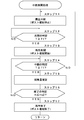
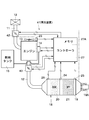
- FIG. 2 is a circuit configuration diagram showing an engine, an exhaust gas purification device, a regeneration device, and the like. It is a flowchart which shows the reproduction
- FIG. 6 is a circuit diagram showing an engine, an exhaust gas purification device, a regeneration device and the like according to a second embodiment of the present invention.
- 1 to 6 show a first embodiment of the present invention.
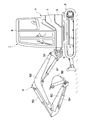
- the hydraulic shovel 1 is a crawler-type lower traveling body 2 capable of self-propelled travel, and an upper revolving body mounted on the lower traveling body 2 so as to be able to turn via the turning device 3 and constituting the vehicle body together with the lower traveling body 2 4 and a working device 5 provided on the front side of the upper swing body 4 so as to be able to move up and down.
- the work device 5 is configured as a swing post type work device, and for example, a swing post 5A, a boom 5B, an arm 5C, a bucket 5D as a work tool, and a swing cylinder 5E that swings the work device 5 left and right.
- the boom cylinder 5F, the arm cylinder 5G and the bucket cylinder 5H are provided (see FIG. 2).
- the upper swing body 4 includes a swing frame 6, an exterior cover 7, a cab 8 and a counterweight 9 which will be described later.
- the pivoting frame 6 forms a structure of the upper pivoting body 4, and the pivoting frame 6 is mounted on the lower traveling body 2 via the pivoting device 3.
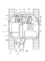
- the swing frame 6 is provided with a counterweight 9 and an engine 10 described later on the rear side, a cab 8 described later on the left front side, and a fuel tank 16 described later on the right front side.
- the turning frame 6 is provided with an exterior cover 7 extending from the right side to the rear side of the cab 8.
- the exterior cover 7 together with the turning frame 6, the cab 8 and the counterweight 9 includes an engine 10, a hydraulic pump 15, and a heat exchanger 17. And a space for accommodating the exhaust gas purification device 18 and the like.
- the cab 8 is mounted on the left front side of the turning frame 6, and the inside of the cab 8 defines an operator's cab on which an operator boardes. Inside the cab 8, a driver's seat on which an operator is seated, various operation levers and the like (all not shown) are provided.
- the counterweight 9 balances the weight with the working device 5, and the counterweight 9 is attached to the rear end of the swing frame 6 while being located on the rear side of the engine 10 described later. As shown in FIG. 2, the rear surface side of the counterweight 9 is formed in an arc shape. The counterweight 9 is configured to fit within the width of the lower traveling body 2.
- Reference numeral 10 denotes an engine disposed laterally on the rear side of the swing frame 6.
- the engine 10 is mounted on a small hydraulic excavator 1 as a prime mover, and is configured using, for example, a small diesel engine.
- the engine 10 is provided with an intake pipe 11 (see FIG. 3) for taking in external air, and an exhaust pipe 12 forming a part of an exhaust gas passage for discharging exhaust gas.
- the intake pipe 11 receives external air into the engine 10, and an air cleaner 13 for cleaning the external air is connected to the tip of the intake pipe 11.
- An exhaust gas purification device 18 described later is connected to the exhaust pipe 12 and provided.
- the engine 10 is driven by injection of fuel.
- the engine 10 is an electronically controlled engine, and the amount of supplied fuel is variably controlled by a fuel injection device 14 (see FIG. 3) including an electronically controlled injection valve. That is, the fuel injection device 14 variably controls the injection amount of the fuel injected into the cylinder (not shown) of the engine 10 based on a control signal output from the controller 27 described later.
- the fuel injection device 14 constitutes a regenerating device 22 (see FIG. 3) together with a controller 27 described later, etc.
- the fuel injection device 14 performs, for example, a regeneration process called post injection according to a control signal of the controller 27. Fuel injection (additional injection after the combustion process) is performed. By this post injection, the temperature of the exhaust gas is raised, and the particulate matter deposited on the particulate matter removal filter 21 of the exhaust gas purification device 18 described later is burned and removed.
- the hydraulic pump 15 is mounted on the left side of the engine 10, and the hydraulic pump 15 constitutes a hydraulic source together with a hydraulic oil tank (not shown).
- the hydraulic pump 15 is driven by the engine 10 to discharge pressure oil (hydraulic oil) toward a control valve (not shown).
- the hydraulic pump 15 is constituted of, for example, a variable displacement swash plate type, an oblique axis type or a radial piston type hydraulic pump.
- the hydraulic pump 15 is not necessarily limited to a variable displacement hydraulic pump, and may be configured using, for example, a fixed displacement hydraulic pump.
- the fuel tank 16 is located on the right side of the cab 8 and provided on the swing frame 6 and is covered with an exterior cover 7 together with a hydraulic oil tank (not shown).
- the fuel tank 16 is formed, for example, as a rectangular pressure-resistant pressure tank, and stores fuel supplied to the engine 10.
- the heat exchanger 17 is located on the right side of the engine 10 and provided on the revolving frame 6, and the heat exchanger 17 includes, for example, a radiator, an oil cooler, and an intercooler. That is, the heat exchanger 17 not only cools the cooling water of the engine 10 but also cools the pressure oil returned to the hydraulic oil tank.
- an exhaust gas purification device 18 for purifying the exhaust gas discharged from the engine 10 will be described.
- reference numeral 18 denotes an exhaust gas purification device provided on the exhaust side of the engine 10. As shown in FIG. 2, the exhaust gas purification device 18 is disposed at the upper left side of the engine 10, for example, at a position above the hydraulic pump 15, and the exhaust pipe 12 of the engine 10 is connected upstream thereof. .
- the exhaust gas purification device 18 constitutes an exhaust gas passage together with the exhaust pipe 12, and removes harmful substances contained in the exhaust gas while the exhaust gas flows from the upstream side to the downstream side.
- the engine 10 formed of a diesel engine is highly efficient and excellent in durability.
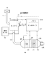
- the exhaust gas of the engine 10 contains harmful substances such as particulate matter (PM), nitrogen oxides (NOx) and carbon monoxide (CO). Therefore, as shown in FIG. 3, the exhaust gas purification device 18 attached to the exhaust pipe 12 includes an oxidation catalyst 20 described later that oxidizes and removes carbon monoxide (CO) and the like in the exhaust gas, and in the exhaust gas. And a particulate matter removal filter 21 described later that collects and removes particulate matter (PM).
- the exhaust gas purification device 18 has, for example, a cylindrical casing 19 configured by detachably connecting a plurality of cylinders before and after.
- an oxidation catalyst 20 called DOC and a particulate matter removal filter 21 called DPF (hereinafter, referred to as a filter 21) are removably accommodated.
- the outlet 19A is located downstream of the filter 21 and connected to the outlet of the casing 19.
- the exhaust port 19A includes, for example, a chimney for discharging exhaust gas after purification processing into the atmosphere, and a silencer.
- the oxidation catalyst 20 is made of, for example, a ceramic cell-like cylinder having an outer diameter size equal to the inner diameter size of the casing 19.
- a large number of through holes (not shown) are formed in the axial direction, and the inner surface is coated with a noble metal.
- the oxidation catalyst 20 oxidizes and removes carbon monoxide (CO), hydrocarbons (HC) and the like contained in the exhaust gas by circulating the exhaust gas in the respective through holes under predetermined temperature conditions. and, for example, it is to remove nitric oxide (NO) as the nitrogen dioxide (NO 2).
- the filter 21 is disposed downstream of the oxidation catalyst 20 in the casing 19.
- the filter 21 collects particulate matter in the exhaust gas discharged from the engine 10, and burns and removes the collected particulate matter to thereby purify the exhaust gas.
- the filter 21 is formed of, for example, a cellular cylinder in which a large number of small holes (not shown) are provided axially in a porous member made of a ceramic material. Thereby, the filter 21 collects the particulate matter through the large number of small holes, and the collected particulate matter is burned and removed by the regeneration treatment of the regeneration device 22 described later. As a result, the filter 21 is regenerated.
- reference numeral 22 denotes a regenerating apparatus for regenerating the filter 21 by burning the particulate matter collected by the filter 21 of the exhaust gas purification device 18.
- the regeneration device 22 is configured to include the above-described fuel injection device 14, a rotation sensor 23 described later, pressure sensors 24 and 25, an exhaust temperature sensor 26, and a controller 27.
- the playback device 22 automatically performs playback based on the determination of the controller 27, that is, based on the operation of the operator.
- the regeneration device 22 performs post injection by the fuel injection device 14 in accordance with a command signal (control signal) of the controller 27. By this post injection, the temperature of the exhaust gas in the exhaust pipe 12 is raised, and the particulate matter deposited on the filter 21 is burned and removed.
- the rotation sensor 23 detects the number of rotations (rotational speed) N of the engine 10.
- the rotation sensor 23 detects the number of rotations N of the engine 10 and outputs a detection signal to a controller 27 described later.
- the controller 27 has, for example, an engine speed N detected by the rotation sensor 23, a fuel injection amount F injected by the fuel injection device 14, and an exhaust temperature (exhaust gas temperature) T detected by an exhaust temperature sensor 26 described later.
- the amount of particulate matter collected by the filter 21 is estimated based on the following equation.
- the controller 27 determines whether or not to perform regeneration based on a first estimated collection amount H1 which is the estimated collection amount.
- the fuel injection amount F can be determined from, for example, an intake air amount detected by an air flow meter (not shown) provided on the intake side of the engine 10 and the engine rotational speed N. Furthermore, the fuel injection amount F can also be calculated from, for example, a control signal (fuel injection command) output from the controller 27 to the fuel injection device 14.
- the pressure sensors 24, 25 are provided on the casing 19 of the exhaust gas purification device 18. As shown in FIG. 3, the pressure sensor 24 is disposed on the inlet side (upstream side) of the filter 21, and the pressure sensor 25 is disposed on the outlet side (downstream side) of the filter 21. It outputs to the controller 27.
- the controller 27 calculates the differential pressure ⁇ P from the pressure P1 on the inlet side detected by the pressure sensor 24 and the pressure P2 on the outlet side detected by the pressure sensor 25, and the differential pressure ⁇ P, the temperature T of the exhaust gas, and the exhaust gas
- the collection amount of particulate matter collected by the filter 21 is estimated based on the flow rate, and it is determined whether or not regeneration is to be performed based on the second estimated collection amount H2, which is the estimated collection amount. I do.
- the exhaust temperature sensor 26 is a temperature detector that detects the temperature (exhaust temperature) T of the exhaust gas discharged from the engine 10. As shown in FIG. 3, the exhaust temperature sensor 26 is attached to the casing 19 of the exhaust gas purification device 18 and detects, for example, an exhaust temperature T discharged from the exhaust pipe 12 side. The exhaust temperature T upstream of the filter 21 detected by the exhaust temperature sensor 26 is output as a detection signal to a controller 27 described later. The exhaust gas temperature T is used to estimate the amount of particulate matter collected by the filter 21 and to determine whether the regeneration is interrupted or restarted.
- the controller 27 includes a microcomputer, the input side of which is connected to the fuel injection device 14, the rotation sensor 23, the pressure sensors 24 and 25, the exhaust temperature sensor 26, an air flow meter (not shown), etc. There is.
- the output side of the controller 27 is connected to the fuel injection device 14 and the like.
- the controller 27 has a memory 27A including a ROM and a RAM.
- the reproduction start threshold Ht [g / l] shown in FIG. 6 set in advance, the first reproduction end threshold He1 [g / l], and the second reproduction end threshold He2 [G / l], an exhaust temperature threshold Tt [° C.], and the like are stored.
- the first map is for determining the discharge amount Hm of the particulate matter discharged from the engine 10 based on the rotation speed N of the engine 10 and the fuel injection amount F.
- the first map for example, the correspondence relationship between the engine speed N, the fuel injection amount F, and the discharge amount Hm of the particulate matter is obtained in advance by experiment, calculation, simulation, etc. It was created.
- a calculation formula for estimating the amount of collection is as follows: the first estimated amount of collection is H1, the amount of emission of particulate matter obtained by the first map is Hm, and the particles removed from the filter 21 by regeneration Assuming that the amount of substance (regeneration amount) is J, it can be expressed as the following equation 1.
- the amount of particulate matter removed by regeneration is, for example, the flow rate of exhaust gas determined from the engine speed N and the fuel injection amount F, the exhaust temperature T, and the engine speed It can be calculated from the relationship between the exhaust temperature of nitrogen oxide (NOx) obtained from N and the fuel injection amount F and the NO 2 conversion rate obtained by adding the exhaust temperature T.
- NOx nitrogen oxide
- the second map is for estimating the collection amount based on the differential pressure ⁇ P of the filter 21.
- the correspondence between the differential pressure ⁇ P, the flow rate of the exhaust gas, and the second estimated trapped amount H2 is obtained in advance by experiment, calculation, simulation, etc., and the correspondence is mapped It was created as
- the flow rate of the exhaust gas can be determined, for example, from the engine speed N and the fuel injection amount F.
- the differential pressure ⁇ P is calculated by the following equation 2.
- the regeneration start threshold Ht [g / l] is a threshold (regeneration start value) of the estimated collection amount H for determining whether to start regeneration. That is, the regeneration start threshold Ht is the first estimated collection amount H1 estimated by the above-described first map and calculation formula, and / or the second estimated collection estimated by the above-described second map When the amount H2 becomes equal to or more than the reproduction start threshold Ht, the determination value is used to determine that the reproduction is necessary.
- the regeneration start threshold value Ht is a determination value for determining whether the particulate matter collected by the filter 21 has become a collection amount necessary for the regeneration process of the filter 21.
- the regeneration start threshold value Ht is a value based on experiments, calculations, simulations, etc. in advance so that regeneration processing can be performed in an appropriate state, for example, in a state where sufficient particulate matter has been collected by the filter 21. Set Thereby, when the particulate matter is sufficiently collected by the filter 21, the regeneration processing can be performed automatically and stably by the regeneration device 22.
- the first regeneration end threshold He1 is an estimated collection amount H for determining whether or not the regeneration of the filter 21 is to be ended when the regeneration of the filter 21 is performed without interruption described later.
- Threshold normal end value
- the first reproduction end threshold value He1 is a first map estimated by the above-described first map and the calculation formula when the reproduction of the filter 21 is performed without ending on its way (without interruption).
- the estimated trapped amount H1 and / or the second estimated trapped amount H2 estimated by the above-mentioned second map becomes equal to or less than the first regeneration end threshold He1
- the particulate matter of the filter 21 is sufficiently It becomes a judgment value for judging that it burned and was removed.
- the first regeneration end threshold He1 determines whether the amount of particulate matter in the filter 21 has been reduced to a sufficiently low residual amount when regeneration of the filter 21 ends normally without interruption. Judgment value.
- the first regeneration end threshold value He1 is set to a smaller value, for example, the amount of particulate matter that can be collected by the filter 21 can be increased until the next regeneration. That is, as the first reproduction end threshold He1 is set smaller, the interval until the start of the next reproduction can be made longer. Therefore, the first reproduction end threshold He1 is set in advance based on experiments, calculations, simulations, etc. so that normal reproduction without interruption can be ended appropriately (with an appropriate remaining amount).
- the second collection end threshold He2 [g / l] is an estimated collection amount H for determining whether or not the resumed regeneration is ended when the regeneration of the filter 21 is interrupted and then resumed. Threshold (resume end value). That is, when the regeneration of the filter 21 is interrupted and then resumed, the second estimated regeneration end threshold He2 is the first estimated collection amount H1 estimated by the above-described first map and calculation formula, and / or When the second estimated collection amount H2 estimated by the above-described second map becomes equal to or less than the second regeneration end threshold He2, this becomes a determination value for determining to end the resumed regeneration.
- the second regeneration end threshold value He2 is a determination value for determining whether the amount of particulate matter in the filter 21 has decreased to a desired remaining amount when the resumed regeneration is ended.
- the second regeneration end threshold He2 is also set to a smaller value similar to the first regeneration end threshold He1, the amount of particulate matter that can be collected by the filter 21 before the next regeneration can be increased. . That is, as the second reproduction end threshold He2 is set smaller, the interval to the next reproduction can be made longer. However, if the second reproduction end threshold He2 is set small (for example, if the second reproduction end threshold He1 is set to the same value as the first reproduction end threshold He1), the resumed reproduction may be continued excessively (the reproduction time may be prolonged). is there.
- the second reproduction end threshold (resumption end value) He2 is set between the reproduction start threshold (reproduction start value) Ht and the first reproduction end threshold (normal end value) He1. ing.
- the second reproduction end threshold He2 is set larger than the first reproduction end threshold He1 and smaller than the reproduction start threshold Ht.
- the second reproduction end threshold He2 is also set in advance based on experiments, calculations, simulations, etc., so that the resumed reproduction can be ended at an appropriate time (reproduction time is not excessively long).
- the exhaust temperature threshold Tt is a threshold of the exhaust temperature T for determining whether to interrupt the regeneration. That is, while the filter 21 is being regenerated, if the exhaust gas temperature T becomes lower than the preset exhaust gas temperature threshold Tt, the estimated collection amount H is the first regeneration end threshold He1 or the second regeneration end. Even if the threshold value He2 is not reached, the reproduction is interrupted. The reason is that even if the regeneration process is continued while the exhaust temperature T is low, the particulate matter can not be sufficiently burned and removed, and the fuel consumption increases due to the post injection while the particulate matter This is to prevent combustion and removal from progressing.
- the exhaust gas temperature threshold Tt is set in advance based on experiments, calculations, simulations, etc. so that the exhaust gas temperature T becomes a boundary value of the exhaust gas temperature T at which the efficiency that is acceptable for regeneration is obtained.
- the controller 27 performs control of automatic reproduction processing that automatically performs reproduction without being based on the operation of the operator, in accordance with processing programs of FIG. 4 and FIG. 5 described later. In this case, in addition to performing processing (control) of start and end of regeneration based on the collection amount of the particulate matter collected by the filter 21, the controller 27 interrupts the regeneration based on the exhaust temperature T and Perform restart processing (control).
- the controller 27 estimates the amount of particulate matter collected by the filter 21 (PM calculation means).
- the collection amount can be estimated based on at least the engine speed N, the fuel injection amount F, and the exhaust temperature T (first estimation means). Further, the collection amount can be estimated based on at least the differential pressure ⁇ P of the filter 21 (second estimation means).
- the collection amount can be estimated using either one or both of the first estimation means and the second estimation means. Depending on the driving situation, the estimation means with high accuracy at that time may be used. Furthermore, the collection amount of particulate matter may be estimated using estimation means other than the first and second estimation means.
- the controller 27 uses the estimated collected amount H to determine whether to start regeneration of the filter 21 (regeneration start) Determination means). Specifically, the controller 27 sets the estimated collection amount H, more specifically, the first estimated collection amount H1 estimated by the first estimation unit and the second estimation unit estimated by the second estimation unit. It is determined that the regeneration of the filter 21 is started when at least one of the estimated collection amount H2 of the above becomes equal to or more than the regeneration start threshold Ht. Next, the controller 27 outputs a control signal indicating post injection to the fuel injection device 14, for example, based on the judgment of the regeneration start (the fact that it becomes the regeneration start threshold Ht or more), and the automatic operation is performed without the operator's operation. Start control of the automatic playback process that performs playback at.
- the controller 27 uses the estimated collection amount H to determine whether or not the regeneration of the filter 21 is to be ended (regeneration end determination means). For example, the controller 27 determines that the estimated collection amount H (at least one of the first estimated collection amount H1 and the second estimated collection amount H2) is the regeneration end threshold (the first regeneration end threshold He1). Alternatively, when the second reproduction end threshold value He2) or less is reached, it is determined that the reproduction of the filter 21 is ended. When it is determined that the regeneration is ended (it becomes equal to or less than the regeneration end threshold), the controller 27 outputs, for example, a control signal to the effect that the post injection is ended to the fuel injection device 14, and ends the control of the automatic regeneration processing. .
- the filter 21 is regenerated as shown in the characteristic line 31 of the two-dot chain line in FIGS. 6 and 7, the estimated collection amount H (first estimated collection amount H1 The process is continued until the second estimated collection amount H2) becomes equal to or less than the first regeneration end threshold He1.
- the characteristic diagram of FIG. 6 shows an example of the time change of the estimated trapped amount H and the exhaust gas temperature T according to the present embodiment.
- the characteristic diagram of FIG. 7 shows an example of the temporal change of the estimated trapped amount H and the exhaust temperature T according to the comparative example.
- regeneration restart processing described later is performed.
- the regeneration restart process as in the present embodiment is not performed, and the estimated collected amount H starts regeneration. Reproduction is started when the threshold value Ht or more is reached.
- the exhaust of the filter 21 is performed.
- the temperature T does not rise sufficiently. Thereby, the reproduction is ended (suspended) halfway.
- the exhaust gas temperature T does not rise sufficiently, there is a risk that the combustion of the particulate matter may not be sufficiently performed even if the regeneration is continued.
- the light load operation or the low rotation state is continued by merely ending the regeneration halfway, as shown by the solid characteristic line 32 in FIG.
- the normal operation is alternately repeated at short intervals.
- the hydraulic actuators (the swing cylinder 5E, the boom cylinder 5F, the arm cylinder 5G, the bucket cylinder 5H, the traveling hydraulic motor, the swing hydraulic motor, etc.) continue to stop for a predetermined time
- the idle control automatically maintains the rotational speed N of the engine 10 in the low rotation state (low idle state). In this case, when the regeneration is started, the possibility of causing the above-mentioned inconvenience increases.
- the controller 27 determines whether or not to resume the interrupted regeneration. It is configured to do. That is, when the exhaust gas temperature T becomes less than the exhaust gas temperature threshold Tt while the regeneration of the filter 21 is being performed, the controller 27 determines that the regeneration of the filter 21 is interrupted (regeneration interruption determination means). In addition to this, the controller 27 determines to restart the regeneration of the filter 21 when the exhaust temperature T becomes equal to or higher than the exhaust temperature threshold Tt when the regeneration is interrupted (regeneration restart determination means).
- the reproduction process including the determination of the interruption of the reproduction and the determination of the restart of the reproduction will be described later with reference to FIGS. 4 and 5.
- the second regeneration end threshold He2 which is a threshold of the estimated collected amount H when ending the resumed regeneration, is a threshold of the estimated collected amount H when the regeneration ends normally without interruption of the regeneration.
- the first reproduction end threshold He1 is set to be larger than the first reproduction end threshold He1. For this reason, even if the exhaust temperature T tends to be difficult to rise due to the continuation of the light load operation and the low rotation state, it is suppressed that the resumed regeneration is continued excessively (regeneration time becomes long). it can.
- the hydraulic shovel 1 according to the first embodiment has the above-described configuration, and its operation will be described next.
- the operator of the hydraulic shovel 1 gets into the cab 8 of the upper revolving superstructure 4 and starts the engine 10 to drive the hydraulic pump 15. Thereby, the pressure oil from the hydraulic pump 15 is supplied to various actuators via the control valve.
- the traveling control lever When the operator boarding the cab 8 operates the traveling control lever, the lower traveling body 2 can be moved forward or backward.
- the work device 5 can be raised and lowered to carry out a digging operation of earth and sand.
- the small hydraulic excavator 1 has a small turning radius by the upper turning body 4, it is possible to perform side groove excavation work while turning the top turning body 4 even in a narrow work site such as an urban area, for example.
- the exhaust gas purification device 18 can oxidize and remove hydrocarbons (HC), nitrogen oxides (NOx) and carbon monoxide (CO) in the exhaust gas by the oxidation catalyst 20.
- the filter 21 collects particulate matter contained in the exhaust gas.
- the purified exhaust gas can be discharged to the outside through the downstream outlet 19A. Further, the collected particulate matter is burned and removed by the regenerator 22 and the filter 21 is regenerated.
- the controller 27 is activated by energization of the accessory or start of the engine 10 (ignition ON).
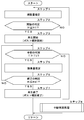
- ignition ON When the processing operation of FIG. 4 is started by this start, in step 1, the amount of trapped particulate matter is estimated.
- the estimation of the collection amount can be performed, for example, by at least one of the following (a) or (b).
- the particulate matter collected by the filter 21 based on the engine speed N of the engine 10, the fuel injection amount F injected from the fuel injection device 14, and the exhaust temperature T of the exhaust gas discharged from the engine 10 The collection amount, that is, the first estimated collection amount H1 is estimated (calculated).
- the first estimated collection amount H1 of the above (a) can be estimated using the first map stored in the memory 27A of the controller 27 and a calculation formula. That is, the emission amount per unit time is determined from the engine speed N and the fuel injection amount F using the above-described first map, and the emission amount is integrated to calculate the total emission from the start of the operation to the present time Find the quantity Hm. Specifically, the first estimated collection amount H1 at the present time is estimated by subtracting the regeneration amount J removed in the regeneration processing up to the present time from the total emission amount Hm based on the above equation 1 can do.
- the engine speed N is read from the rotation sensor 23.
- the fuel injection amount F can be determined, for example, from the amount of intake air detected by an air flow meter (not shown) provided on the intake side of the engine 10 and the engine speed N. Furthermore, the fuel injection amount F can also be calculated from, for example, a control signal (fuel injection command) output from the controller 27 to the fuel injection device 14.
- the exhaust temperature T is read from the exhaust temperature sensor 26.
- the second estimated collection amount H2 of the above (b) can be estimated using the above-mentioned second map stored in the memory 27A of the controller 27. That is, the second estimated collection amount H2 at the present time can be estimated based on the second map in which the differential pressure ⁇ P, the exhaust gas flow rate and the estimated collection amount H correspond to each other.
- the differential pressure ⁇ P is calculated from the pressure P1 on the upstream side of the filter 21 read from the pressure sensor 24 and the pressure P2 on the downstream side read from the pressure sensor 25 using the above equation (2).
- step 1 it is determined whether or not automatic reproduction is to be performed. Specifically, for example, whether or not to perform automatic regeneration is determined based on whether or not the estimated collection amount H is equal to or more than a preset regeneration start threshold Ht. If it is determined in this step 2 that "NO", that is, the estimated collection amount H is smaller than the regeneration start threshold Ht, the particulate matter is not collected to such an extent that the filter 21 needs to be regenerated ( It is considered that the filter 21 is not clogged. In this case, the process returns to the front of step 1 and the processing after step 1 is repeated.
- step 3 reproduction is started. That is, in step 3, the controller 27 outputs a control signal to post injection to the fuel injection device 14. As a result, the exhaust temperature T from the engine 10 is raised, and the particulate matter collected by the filter 21 is burned and removed.
- step 4 it is determined based on the exhaust temperature T whether or not the regeneration is to be interrupted. That is, if the regeneration is continued while the exhaust gas temperature T is low, the fuel consumption may increase due to the post injection, but the combustion and removal of the particulate matter may not proceed. Therefore, in step 4, it is determined whether the exhaust gas temperature T is equal to or higher than the exhaust gas temperature threshold Tt.
- the exhaust temperature T is read from the exhaust temperature sensor 26.
- step 4 If it is determined in step 4 that “YES”, that is, the exhaust temperature T is equal to or higher than the exhaust temperature threshold Tt, the process proceeds to step 5.
- step 5 the amount of trapped particulate matter is estimated as in step 1 described above.
- step 6 based on the estimated collected amount H obtained in step 5, it is judged whether or not the automatic regeneration is ended. That is, in step 6, for example, it is determined whether or not the regeneration is to be ended depending on whether or not the estimated collection amount H is equal to or less than the first regeneration end threshold He1 set in advance.
- step 6 If it is determined in step 6 that "NO", that is, the estimated collection amount H is larger than the first regeneration end threshold He1, the amount of particulate matter burned and removed by regeneration is not sufficient yet, in other words, If so, the amount of particulate matter remaining in the filter 21 is considered to be large. In this case, the process returns to the front of step 4, and the processing after step 4 is repeated.
- step 6 determines whether “YES” is determined in step 6, that is, if it is determined that the estimated collected amount H is equal to or less than the first regeneration end threshold He1, particulate matter in the filter 21 is sufficiently burned and removed by regeneration. It is thought that In this case, the process proceeds to step 7.
- step 7 the reproduction is ended. That is, in step 7, the controller 27 outputs a control signal to the effect that the post injection is ended to the fuel injection device 14. By this, the reproduction is ended, and the process returns to the start through the return, and the processing after step 1 is repeated.
- step 4 determines whether the exhaust temperature T is less than the exhaust temperature threshold Tt. If "NO”, that is, if it is determined in step 4 that the exhaust temperature T is less than the exhaust temperature threshold Tt, the process proceeds to the regeneration interruption / resumption processing of step 8. That is, in this case, it is considered that the exhaust temperature T is low, and sufficient combustion of the particulate matter can not be expected even if the regeneration is continued. Therefore, the process proceeds to step 8 in order to interrupt the reproduction and to restart it thereafter.
- the reproduction interruption / resumption processing of step 8 is the processing of steps 11 to 17 shown in FIG. That is, in step 11, since the exhaust gas temperature T is less than the exhaust gas temperature threshold Tt, the regeneration is interrupted. Specifically, the controller 27 outputs a control signal to the fuel injection device 14 to interrupt (temporarily end) the post injection. This interrupts playback.
- step 12 it is determined based on the exhaust temperature T whether or not to resume the regeneration. That is, when the exhaust gas temperature T becomes high, if regeneration is restarted, combustion and removal of the particulate matter collected by the filter 21 can be promoted. Therefore, in step 12, it is determined whether the exhaust gas temperature T is equal to or more than the exhaust gas temperature threshold Tt.
- step 12 If it is determined in step 12 that “NO”, that is, the exhaust temperature T is less than the exhaust temperature threshold Tt, sufficient regeneration of the filter 21 can not be expected even if reactivation of the filter 21 is resumed. It waits in step 12 (the process of step 12 is repeated).
- step 12 determines whether the exhaust gas temperature T is equal to or higher than the exhaust gas temperature threshold Tt. If “YES" is determined in step 12, that is, if it is determined that the exhaust gas temperature T is equal to or higher than the exhaust gas temperature threshold Tt, the process proceeds to step 13, and the regeneration is restarted. That is, in step 13, the controller 27 outputs a control signal to the effect that post injection is performed to the fuel injection device 14. Thereby, the particulate matter deposited on the filter 21 is burned and removed.
- step 14 it is determined based on the exhaust temperature T whether or not the regeneration is to be interrupted. That is, when the resumed regeneration is continued while the exhaust gas temperature T is low, the fuel consumption may increase due to the post injection, but the particulate matter may not be burned or removed. Therefore, in step 14, as in the case of step 12 described above, it is determined whether the exhaust gas temperature T is equal to or higher than the exhaust gas temperature threshold Tt.
- step 14 If it is determined in step 14 that “YES”, that is, the exhaust temperature T is equal to or higher than the exhaust temperature threshold Tt, the process proceeds to step 15.
- step 15 the amount of trapped particulate matter is estimated as in the above-described steps 1 and 5.
- step 16 based on the estimated collected amount H obtained in step 15, it is judged whether or not the resumed regeneration is to be ended. That is, in step 16, for example, it is determined whether or not to resume the resumed regeneration based on whether or not the estimated collection amount H is equal to or less than the second regeneration end threshold He2 set in advance.
- step 16 If it is determined in step 16 that "NO", that is, the estimated collection amount H is larger than the second regeneration end threshold He2, then the amount of particulate matter burned and removed by regeneration is not sufficient yet, in other words, If so, the amount of particulate matter remaining in the filter 21 is considered to be still large. In this case, the process returns to the front of step 14 and repeats the processing after step 14.
- step 17 the reproduction is ended. That is, at step 17, the controller 27 outputs a control signal to the effect that the post injection is ended to the fuel injection device 14. As a result, the reproduction is ended, and the process returns to the start through the return of FIG. 5 and the return of FIG.
- step 14 determines whether the exhaust temperature T is less than the exhaust temperature threshold Tt. If it is determined in step 14 that “NO”, that is, the exhaust temperature T is less than the exhaust temperature threshold Tt, the process returns to the front of step 11. That is, although the regeneration was restarted when the exhaust temperature T became equal to or higher than the exhaust temperature threshold Tt, thereafter, even if the exhaust temperature T becomes lower than the exhaust temperature threshold Tt and the resumed regeneration is continued, the particulate matter is sufficient It can not be anticipated that the Therefore, the process returns to the step before step 11, and the processing after step 11 (processing for interrupting and resuming reproduction) is repeated.
- the regeneration of the filter 21 is interrupted in the process of step 4 when the exhaust gas temperature T becomes less than the exhaust gas temperature threshold Tt while the regeneration of the filter 21 is performed.
- the regeneration of the filter 21 is interrupted in the subsequent processing of step 8, more specifically, in the processing of step 11.
- the next regeneration is started when the estimated collected amount H of particulate matter of the filter 21 becomes equal to or more than the regeneration start value Ht.
- the exhaust gas temperature T is restarted when it becomes equal to or higher than the exhaust gas temperature threshold Tt. That is, even if the exhaust temperature T becomes low and the regeneration is interrupted, when the exhaust temperature T becomes equal to or higher than the exhaust temperature threshold Tt, the regeneration is resumed by the processing of step 12 and the subsequent step 13.
- the filter 21 can be suppressed that the normal operation continues until the estimated collection amount H becomes equal to or more than the preset regeneration start value Ht. In other words, even if the regeneration is interrupted by the decrease of the exhaust temperature T, the regeneration is resumed by the process of step 12 and the subsequent step 13, as shown by the characteristic line 33 in FIG. The combustion and removal of the particulate matter collected by the filter 21 can be promoted.
- the characteristic line 32 in FIG. 7 as a comparative example, it is possible to suppress repetition of the regeneration operation and the normal operation at short intervals for a long period of time, and the working environment deteriorates. It can suppress giving a feeling of discomfort.
- fuel consumption can be reduced (low fuel consumption), excessive deposition can be suppressed, and oil dilution can be suppressed, and the stability and reliability of the regenerating apparatus 22 and thus the hydraulic shovel 1 can be improved. It can be improved.
- step 16 whether or not the regeneration resumed by the process of step 12 and the subsequent step 13 is ended depends on the process of step 16, that is, the estimated collection amount H is the second regeneration. It is judged by whether or not it is less than the end threshold value He2. On the other hand, if it is determined in step 4 that “NO” is not determined, that is, if regeneration proceeds without interruption of regeneration, it is determined in step 6 whether or not the regeneration is terminated. It is judged by whether or not it is equal to or less than the reproduction end threshold He1 of 1.
- the second reproduction end threshold (resumption end value) He2 is set between the reproduction start threshold (reproduction start value) Ht and the first reproduction end threshold (normal end value) He1.
- the second reproduction end threshold He2 is set to a value larger than the first reproduction end threshold He1 and smaller than the reproduction start threshold Ht. For this reason, even if the exhaust temperature T tends to be difficult to rise due to the continuation of the light load operation and the standby state in the low rotation state, the regeneration resumed by the processing of step 12 and step 13 following this is excessively continued. It is possible to suppress (the reproduction time becomes long). That is, compared with the case where the second reproduction end threshold He2 is set to be the same as the first reproduction end threshold He1, the resumed reproduction can be ended earlier. As a result, also from this point of view, it is possible to suppress giving the operator a sense of discomfort.
- step 1 of FIG. 4, step 5 and step 15 of FIG. 5 is a specific example of the PM calculating means of the present invention
- the process of step 2 of FIG. Shows a specific example of the reproduction start judging means.
- the process of step 4 of FIG. 4 and the process of step 14 of FIG. 5 show a specific example of the reproduction interruption determination means which is a component of the present invention
- the process of step 12 of FIG. 5 is a component of the present invention.
- the specific example of the determination means is shown.
- the process of step 6 of FIG. 4 and the process of step 16 of FIG. 5 correspond to a specific example of the reproduction end determination means.
- FIG. 8 shows a second embodiment of the present invention.
- the feature of the second embodiment is that, in the regeneration, the flow path of at least one of an intake throttle valve provided on the intake side of the engine and an exhaust throttle valve provided on the exhaust side, not post injection, is used.
- the configuration is such that the operation is performed by operating in the narrowing direction.
- the same components as those in the first embodiment described above are denoted by the same reference numerals, and the description thereof will be omitted.
- reference numeral 41 denotes a regenerating apparatus for regenerating the filter 21 by burning the particulate matter collected by the filter 21.
- the regeneration device 41 includes a fuel injection device 14, an intake throttle valve 42, an exhaust throttle valve 43, a rotation sensor 23, pressure sensors 24 and 25, an exhaust temperature sensor 26 and a controller 27.
- the particulate matter deposited on the filter 21 is operated by operating the flow passage of at least one of the intake throttle valve 42 and the exhaust throttle valve 43 in a direction to narrow the flow path. Burn and remove.
- the intake throttle valve 42 is provided on the side of the intake pipe 11 of the engine 10, and the intake throttle valve 42 constitutes a regeneration device 41 that regenerates the filter 21.
- the intake air throttle valve 42 is normally held in an open state (for example, an opening degree corresponding to the fuel injection amount F or a fully open state) by a control signal from the controller 27.
- the intake throttle valve 42 is operated in the direction to narrow the flow path by the control signal from the controller 27.
- the intake air throttle valve 42 throttles the amount of intake air so that the air-fuel ratio of air and fuel tends to be rich.
- the temperature of the exhaust gas discharged to the exhaust pipe 12 side rises by burning the fuel whose air-fuel ratio tends to be rich, and the particulate matter collected by the filter 21 Can be burned and removed.
- the exhaust throttle valve 43 is provided on the exhaust pipe 12 side of the engine 10, and the exhaust throttle valve 43 also constitutes a regeneration device 41 that regenerates the filter 21.
- the exhaust throttle valve 43 is held in a fully open state at normal times by a control signal from the controller 27.
- the exhaust throttle valve 43 is operated in the direction to narrow the flow path by the control signal from the controller 27, and control is performed to narrow the opening degree.
- the exhaust throttle valve 43 throttles the flow rate of the exhaust gas flowing in the exhaust pipe 12 to apply a back pressure to the engine 10 to increase the load on the engine 10.
- the controller 27 increases the fuel injection amount F by the fuel injection device 14 of the engine 10 correspondingly to the load. As a result, the temperature of the exhaust gas rises, and the particulate matter collected by the filter 21 can be burned and removed.
- the regeneration is performed by operating the flow passage of at least one of the intake throttle valve 42 and the exhaust throttle valve 43 as described above in the direction in which the throttle valve is narrowed. There is no particular difference from the first embodiment described above.
- the regeneration is performed by operating the flow passage of at least one of the intake throttle valve 42 and the exhaust throttle valve 43 in the direction to narrow the flow, so the regeneration is performed after the post injection It can be carried out at a lower temperature than in the case of Thereby, the durability of the filter 21 can be improved.
- the first estimated collection amount H1 is described as being estimated based on the engine speed N, the fuel injection amount F, and the exhaust temperature T as an example.
- the present invention is not limited to this.
- the first estimated collection amount H1 can be calculated not only by the engine speed N, the fuel injection amount F, and the exhaust temperature T, but also the temperature of each part such as the filter, the engine load It is good also as composition performed using a state quantity (state quantity showing a driving state) etc. etc. collectively.
- exhaust gas purification device 18 was constituted by oxidation catalyst 20 and filter 21 was mentioned as an example, and was explained.
- the present invention is not limited to this.
- a urea injection valve, a selective reduction catalyst device or the like may be used in combination.
- the construction machine provided with the exhaust gas purification device according to the present invention is not limited to this, and may be applied to, for example, medium-sized or larger hydraulic shovels.
- the present invention can be widely applied to construction machines such as hydraulic excavators, wheel loaders, forklifts, hydraulic cranes and the like provided with a wheel type lower traveling body.
Abstract
Description
2 下部走行体(車体)
4 上部旋回体(車体)
10 エンジン
18 排気ガス浄化装置
21 フィルタ
22,41 再生装置
26 排気温センサ
27 コントローラ
H 推定捕集量
Ht 再生開始閾値
He1 第1の再生終了閾値
He2 第2の再生終了閾値
T 排気温度
Tt 排気温度閾値 1 Hydraulic excavator (construction machine)
2 Lower body (body)
4 Upper revolving body (car body)
Claims (2)
- 車体(2,4)と、該車体(2,4)に搭載され燃料の噴射により駆動されるエンジン(10)と、該エンジン(10)から排出される排気ガス中の粒子状物質を捕集するフィルタ(21)を有し前記エンジン(10)の排気側に設けられる排気ガス浄化装置(18)と、該排気ガス浄化装置(18)のフィルタ(21)に捕集された粒子状物質を燃焼させることにより該フィルタ(21)の再生を行う再生装置(22,41)とを備えてなる建設機械において、
前記再生装置(22,41)は、
前記エンジン(10)から排出された排気ガスの温度(T)を検出する温度検出器(26)と、
前記フィルタ(21)に捕集された粒子状物質の捕集量(H)を推定するPM演算手段と、
該PM演算手段により推定された推定捕集量(H)が予め設定された再生開始値(Ht)以上になったときに、前記フィルタ(21)の再生を開始するとの判定をする再生開始判定手段と、
前記フィルタ(21)の再生を行っている間に、前記温度検出器(26)により検出された排気温度(T)が予め設定された所定温度(Tt)未満になると、前記フィルタ(21)の再生を中断するとの判定をする再生中断判定手段と、
該再生中断判定手段の判定に基づいて前記フィルタ(21)の再生が中断された場合に、前記排気温度(T)が前記所定温度(Tt)以上になると、前記フィルタ(21)の再生を再開するとの判定をする再生再開判定手段とを備える構成としたことを特徴とする建設機械。 The vehicle body (2, 4), an engine (10) mounted on the vehicle body (2, 4) and driven by injection of fuel, and particulate matter in exhaust gas discharged from the engine (10) And an exhaust gas purification device (18) provided on the exhaust side of the engine (10) and a particulate matter collected by the filter (21) of the exhaust gas purification device (18). In a construction machine comprising a regeneration device (22, 41) for regenerating the filter (21) by burning it,
The playback device (22, 41)
A temperature detector (26) for detecting the temperature (T) of the exhaust gas discharged from the engine (10);
PM calculating means for estimating the amount (H) of collected particulate matter collected by the filter (21);
Regeneration start determination to determine that regeneration of the filter (21) should be started when the estimated amount of collection (H) estimated by the PM calculation means becomes equal to or greater than a preset regeneration start value (Ht) Means,
When the exhaust gas temperature (T) detected by the temperature detector (26) becomes lower than a predetermined temperature (Tt) set in advance during regeneration of the filter (21), the filter (21) is Reproduction interruption determination means for judging that reproduction is to be interrupted;
When the regeneration of the filter (21) is interrupted based on the determination of the regeneration interruption determination means, the regeneration of the filter (21) is resumed when the exhaust temperature (T) becomes equal to or higher than the predetermined temperature (Tt). A construction machine comprising: a regeneration restart judging means for judging that it is. - 前記フィルタ(21)の再生がその中断なく正常に終了する場合に前記PM演算手段により推定される推定捕集量(H)を正常終了値(He1)とし、前記再生再開判定手段の判定に基づいて再開された再生を終了する場合に前記PM演算手段により推定される推定捕集量(H)を再開終了値(He2)とすると、該再開終了値(He2)は、前記再生開始値(Ht)と前記正常終了値(He1)の間に設定してなる請求項1に記載の建設機械。 When the regeneration of the filter (21) ends normally without interruption, the estimated amount of collection (H) estimated by the PM calculation means is taken as the normal end value (He1), and based on the judgment of the regeneration resumption judgment means Assuming that the estimated collection amount (H) estimated by the PM calculation means is a restart end value (He2) when the regeneration which has been restarted is ended, the restart end value (He2) is the regeneration start value (Ht). The construction machine according to claim 1, wherein the construction machine is set between the normal end value (He1) and the normal end value (He1).
Priority Applications (4)
| Application Number | Priority Date | Filing Date | Title |
|---|---|---|---|
| EP14839362.2A EP3040528B1 (en) | 2013-08-30 | 2014-08-05 | Construction machine |
| US14/785,056 US9540983B2 (en) | 2013-08-30 | 2014-08-05 | Construction machine |
| CN201480025687.2A CN105189953B (en) | 2013-08-30 | 2014-08-05 | Engineering machinery |
| KR1020157031568A KR101728797B1 (en) | 2013-08-30 | 2014-08-05 | Construction machine |
Applications Claiming Priority (2)
| Application Number | Priority Date | Filing Date | Title |
|---|---|---|---|
| JP2013180284A JP5863731B2 (en) | 2013-08-30 | 2013-08-30 | Construction machinery |
| JP2013-180284 | 2013-08-30 |
Publications (1)
| Publication Number | Publication Date |
|---|---|
| WO2015029716A1 true WO2015029716A1 (en) | 2015-03-05 |
Family
ID=52586288
Family Applications (1)
| Application Number | Title | Priority Date | Filing Date |
|---|---|---|---|
| PCT/JP2014/070614 WO2015029716A1 (en) | 2013-08-30 | 2014-08-05 | Construction machine |
Country Status (6)
| Country | Link |
|---|---|
| US (1) | US9540983B2 (en) |
| EP (1) | EP3040528B1 (en) |
| JP (1) | JP5863731B2 (en) |
| KR (1) | KR101728797B1 (en) |
| CN (1) | CN105189953B (en) |
| WO (1) | WO2015029716A1 (en) |
Families Citing this family (4)
| Publication number | Priority date | Publication date | Assignee | Title |
|---|---|---|---|---|
| FR3057612B1 (en) * | 2016-10-18 | 2019-11-15 | Renault S.A.S | PROCESS FOR PURGING A NITROGEN OXIDE TRAP FROM AN INTERNAL COMBUSTION ENGINE AND ASSOCIATED MOTORIZATION DEVICE |
| KR102111955B1 (en) * | 2019-12-13 | 2020-05-18 | 화이버텍(주) | Dpf regeneration system and dpf regeneration method |
| GB2595436A (en) * | 2020-03-12 | 2021-12-01 | Cargotec Patenter Ab | An electronic engine management system and method for a truck mounted forklift |
| CN113356985B (en) * | 2021-06-02 | 2022-06-03 | 重庆长安汽车股份有限公司 | Regeneration control method, device and system for particle catcher and vehicle |
Citations (6)
| Publication number | Priority date | Publication date | Assignee | Title |
|---|---|---|---|---|
| JP2000161044A (en) | 1998-12-01 | 2000-06-13 | Toyota Motor Corp | Regeneration control device for particulate filter |
| JP2005256720A (en) * | 2004-03-11 | 2005-09-22 | Toyota Motor Corp | Exhaust emission control device for internal combustion engine |
| JP2005299456A (en) * | 2004-04-09 | 2005-10-27 | Isuzu Motors Ltd | Control method of exhaust gas purification system, and exhaust gas purification system |
| JP2010065577A (en) | 2008-09-09 | 2010-03-25 | Hitachi Constr Mach Co Ltd | Engine control system for work machine |
| JP2010156281A (en) * | 2008-12-26 | 2010-07-15 | Mitsubishi Heavy Ind Ltd | Regeneration control device of dpf |
| JP2013231376A (en) * | 2012-04-27 | 2013-11-14 | Iseki & Co Ltd | Working vehicle |
Family Cites Families (9)
| Publication number | Priority date | Publication date | Assignee | Title |
|---|---|---|---|---|
| JP2004162613A (en) * | 2002-11-13 | 2004-06-10 | Mitsubishi Fuso Truck & Bus Corp | Exhaust emission control device for internal combustion engine |
| JP2004197657A (en) * | 2002-12-18 | 2004-07-15 | Nissan Motor Co Ltd | Reproducing apparatus for particulate filter and engine waste gas purifying facility |
| JP3912289B2 (en) * | 2003-01-10 | 2007-05-09 | 日産自動車株式会社 | Particulate filter regeneration device and engine exhaust gas purification device |
| DE602004004221T2 (en) * | 2003-09-19 | 2007-05-03 | Nissan Motor Co., Ltd., Yokohama | Regeneration control of a filter |
| JP4075795B2 (en) * | 2003-12-19 | 2008-04-16 | 日産自動車株式会社 | Diesel engine exhaust aftertreatment system |
| JP5275200B2 (en) * | 2009-10-08 | 2013-08-28 | 日立建機株式会社 | Exhaust treatment equipment for construction machinery |
| JP5614996B2 (en) * | 2010-01-28 | 2014-10-29 | 三菱重工業株式会社 | Exhaust gas treatment method and apparatus for internal combustion engine |
| JP5828578B2 (en) * | 2010-05-07 | 2015-12-09 | ヤンマー株式会社 | Exhaust gas purification system |
| JP5540927B2 (en) * | 2010-06-21 | 2014-07-02 | トヨタ自動車株式会社 | Fault detection device for differential pressure sensor |
-
2013
- 2013-08-30 JP JP2013180284A patent/JP5863731B2/en active Active
-
2014
- 2014-08-05 KR KR1020157031568A patent/KR101728797B1/en active IP Right Grant
- 2014-08-05 EP EP14839362.2A patent/EP3040528B1/en active Active
- 2014-08-05 US US14/785,056 patent/US9540983B2/en active Active
- 2014-08-05 CN CN201480025687.2A patent/CN105189953B/en active Active
- 2014-08-05 WO PCT/JP2014/070614 patent/WO2015029716A1/en active Application Filing
Patent Citations (6)
| Publication number | Priority date | Publication date | Assignee | Title |
|---|---|---|---|---|
| JP2000161044A (en) | 1998-12-01 | 2000-06-13 | Toyota Motor Corp | Regeneration control device for particulate filter |
| JP2005256720A (en) * | 2004-03-11 | 2005-09-22 | Toyota Motor Corp | Exhaust emission control device for internal combustion engine |
| JP2005299456A (en) * | 2004-04-09 | 2005-10-27 | Isuzu Motors Ltd | Control method of exhaust gas purification system, and exhaust gas purification system |
| JP2010065577A (en) | 2008-09-09 | 2010-03-25 | Hitachi Constr Mach Co Ltd | Engine control system for work machine |
| JP2010156281A (en) * | 2008-12-26 | 2010-07-15 | Mitsubishi Heavy Ind Ltd | Regeneration control device of dpf |
| JP2013231376A (en) * | 2012-04-27 | 2013-11-14 | Iseki & Co Ltd | Working vehicle |
Also Published As
| Publication number | Publication date |
|---|---|
| KR20150137122A (en) | 2015-12-08 |
| CN105189953B (en) | 2017-10-13 |
| JP5863731B2 (en) | 2016-02-17 |
| EP3040528A4 (en) | 2017-04-12 |
| US9540983B2 (en) | 2017-01-10 |
| KR101728797B1 (en) | 2017-04-20 |
| US20160084134A1 (en) | 2016-03-24 |
| EP3040528A1 (en) | 2016-07-06 |
| CN105189953A (en) | 2015-12-23 |
| EP3040528B1 (en) | 2018-06-27 |
| JP2015048763A (en) | 2015-03-16 |
Similar Documents
| Publication | Publication Date | Title |
|---|---|---|
| JP5815749B2 (en) | Construction machinery | |
| WO2012172951A1 (en) | Construction machine | |
| KR101734977B1 (en) | Construction machine | |
| WO2013077130A1 (en) | Construction machine | |
| JP5420513B2 (en) | Hydraulic working machine | |
| JP5815748B2 (en) | Construction machinery | |
| WO2015029716A1 (en) | Construction machine | |
| JP6353797B2 (en) | Engine and work vehicle equipped with the engine | |
| JP2015017589A (en) | Construction machine | |
| JP5320123B2 (en) | Work vehicle and control method of work vehicle | |
| JP6618494B2 (en) | Construction machinery |
Legal Events
| Date | Code | Title | Description |
|---|---|---|---|
| WWE | Wipo information: entry into national phase |
Ref document number: 201480025687.2 Country of ref document: CN |
|
| 121 | Ep: the epo has been informed by wipo that ep was designated in this application |
Ref document number: 14839362 Country of ref document: EP Kind code of ref document: A1 |
|
| WWE | Wipo information: entry into national phase |
Ref document number: 14785056 Country of ref document: US |
|
| ENP | Entry into the national phase |
Ref document number: 20157031568 Country of ref document: KR Kind code of ref document: A |
|
| REEP | Request for entry into the european phase |
Ref document number: 2014839362 Country of ref document: EP |
|
| WWE | Wipo information: entry into national phase |
Ref document number: 2014839362 Country of ref document: EP |
|
| NENP | Non-entry into the national phase |
Ref country code: DE |