EP3040486B1 - Vorrichtung zum befestigen und nivellieren von sanitärarmaturen auf wänden - Google Patents
Vorrichtung zum befestigen und nivellieren von sanitärarmaturen auf wänden Download PDFInfo
- Publication number
- EP3040486B1 EP3040486B1 EP15192906.4A EP15192906A EP3040486B1 EP 3040486 B1 EP3040486 B1 EP 3040486B1 EP 15192906 A EP15192906 A EP 15192906A EP 3040486 B1 EP3040486 B1 EP 3040486B1
- Authority
- EP
- European Patent Office
- Prior art keywords
- fastening
- wall
- levelling
- laminar body
- extension
- Prior art date
- Legal status (The legal status is an assumption and is not a legal conclusion. Google has not performed a legal analysis and makes no representation as to the accuracy of the status listed.)
- Not-in-force
Links
- 238000009434 installation Methods 0.000 description 4
- 239000002184 metal Substances 0.000 description 2
- 229910052751 metal Inorganic materials 0.000 description 2
- 238000004519 manufacturing process Methods 0.000 description 1
- 238000009428 plumbing Methods 0.000 description 1
- 238000003466 welding Methods 0.000 description 1
Images


Classifications
-
- E—FIXED CONSTRUCTIONS
- E03—WATER SUPPLY; SEWERAGE
- E03C—DOMESTIC PLUMBING INSTALLATIONS FOR FRESH WATER OR WASTE WATER; SINKS
- E03C1/00—Domestic plumbing installations for fresh water or waste water; Sinks
- E03C1/02—Plumbing installations for fresh water
- E03C1/021—Devices for positioning or connecting of water supply lines
-
- E—FIXED CONSTRUCTIONS
- E03—WATER SUPPLY; SEWERAGE
- E03C—DOMESTIC PLUMBING INSTALLATIONS FOR FRESH WATER OR WASTE WATER; SINKS
- E03C1/00—Domestic plumbing installations for fresh water or waste water; Sinks
- E03C1/02—Plumbing installations for fresh water
- E03C1/04—Water-basin installations specially adapted to wash-basins or baths
- E03C1/042—Arrangements on taps for wash-basins or baths for connecting to the wall
Definitions
- This invention refers to a device for fastening and levelling sanitary fittings onto walls with respect to the three coordinate axes.
- each wall onto which sanitary fittings are to be installed creates a different angle with respect to a vertical plane.
- walls usually comprise irregularities that make the fastening of said fittings with the desired arrangement even more complicated.
- Document EP0609973A1 is known in the state of the art. It relates to a device for fastening installation elements on a wall, comprising two metal plates telescopically assembled with two profiles at the final edges of the assembly, displaced from the metal plates.
- the device comprises a central orifice in one of the profiles and two lateral orifices in each of both profiles. Therefore the device may be aligned according to both directions defining the surface of the wall.
- Document DE102007055565B3 discloses a device for flush mounting of sanitary elements on walls, formed from a mounting plate and several support plates provided for the assembly of sanitary element.
- the device comprises fastening areas in both longitudinal edges spaced from the mounting plate.
- the mounting plate comprises several orifices for the leveling of the device according to both directions defining the surface of the wall where it is fixed, so as several notches for the assembly of the support plates.
- Document DE 10 2011 082 120 A1 (cf. in particular figure 7) provides a device (terminal block) with a plate that is screwed to a base where additional screws are screwed.
- the plate leans against the heads of said screws and comprises openings to access to the screw heads.
- the axial extensions of the screws determine the alignment of the plate.
- the present invention describes a device for fastening and levelling sanitary fitting onto walls, comprising a laminar body, which in turn comprises a front side to be arranged facing the sanitary fittings fastened to the laminar body; and a rear side to be arranged facing the wall.
- the device according to the invention comprises: two profiles, one in an upper edge and another one in a lower edge of the laminar body based on how the device is fastened to the wall, both profiles being arranged in a displaced plane relative to the laminar body towards the rear side; fastening orifices to fasten the device to the wall, which comprise a central orifice arranged in a middle point of the longitudinal extension of the profile of the upper edge and lateral orifices at least in the profile of the upper edge; and levelling means arranged in the laminar body, each of which being individually adjustable throughout its length with respect to the rear side and providing support against the wall.
- each extension element has a head at one end and a support at the other end.
- the head provides a handling point for the user which is arranged in the front side of the body such that it is still accessible after mounting the device to the wall.
- Each extension element is immobilized by means of a locknut.
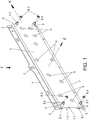
- the present invention describes a device for fastening and levelling sanitary fittings onto walls (8), despite them being walls (8) with undesired inclination and/or superficial irregularities.
- the present device is simple and easy to use for obtaining a desired orientation with respect to a horizontal coordinate axis (X), a vertical coordinate axis (Y) and a depth coordinate axis (Z), that is to say with respect to each of the three coordinate axes (X, Y, Z).
- the present device comprises a laminar body (1), which in turn comprises a front side (1.1) and a rear side (1.2).
- the front side (1.1) is configured to be arranged facing the fittings which are fastened to the device through housings (9). Said fastening is carried out by partially inserting the fittings in the housings (9) or through conventional fastening means in said housings (9).
- the rear side (1.2) whereas is configured to be arranged facing the surface or wall (8) onto which the device which is the object of the present invention is fastened.
- the laminar body (1) comprises several lengths depending on the number of fittings to be housed. Should the number of fittings be higher than one, these are to be arranged with respect to the horizontal coordinate axis (X), as it is shown in Figures 2 and 4 . Therefore, the dimensions, and especially the horizontal extension, are variable, depending on the number and size of fittings to be housed.
- the device also comprises fastening orifices (2, 3) with the aim of fastening the device to the wall (8).
- the fastening orifices (2, 3) comprise a central orifice (2) and at least two lateral orifices (3), one at each side of the central orifice (2), with respect to the horizontal coordinate axis (X).
- the central orifice (2) is an elongated orifice such that it has a linear stretch in an upward direction according to the position for use of the present device. This linear stretch has smaller dimensions than the rest of the orifices used for its levelling. Said central orifice (2) is clearly seen in Figures 1 and 2 .
- the present device comprises two profiles (7), arranged externally to the laminar body (1) in an upper edge and in a lower edge of the device, forming a step-shaped configuration with respect to the laminar body (1) towards the rear side (1.2), thus being located in a parallel plane with respect to the laminar body (1).
- the profiles (7) are configured to act as contact areas with the walls (8). Therefore, by means of the U-shaped transverse section, a cavity or hollow is created, which may attain the goal of solving irregularities on the walls (8) where the present device is fastened, thus facilitating both its fastening and levelling.
- the fastening orifices (2, 3) are arranged in the profiles (7) and are configured to be crossed by elements such as nails and screws to fasten this device to the wall (8).
- the central orifice (2) is arranged in the middle point of the horizontal longitudinal extension of the profile (7) arranged on the upper edge of the device, and on each of side of said orifice (2) there is at least one of the lateral orifices (3) also in said profile (7) separated with respect to the central orifice (2) to provide a stable fastening.
- the device comprises one of the lateral orifices (3) in each of the corners of the device.
- no central orifice (2) is arranged, but two of the lateral orifices (3) separated from each other are included so as to provide the device with stable fastening.
- the device which is the object of the present invention also comprises levelling means (5, 6).
- the number and the location of the levelling means (5, 6) vary based on aspects such as the dimensions of the device, number and weight of the fittings to be housed, status of the wall (8), etc.
- the device comprises one of the levelling means (5, 6) in each of the corners of the laminar body (1).
- Each of the levelling means (5, 6) comprises an internally threaded body (5) and an externally threaded extension element (6) to be threadable through the threaded body (5) by a user manipulating the present device.
- the threaded body (5) is arranged making up a unitary element together with the laminar body (1), although in another preferred embodiment they are independent elements joined to the laminar body (1), for example, by welding, now stapling
- each of the extension elements (6) is arranged threaded through the related threaded body (5), also passing through the laminar body (1).
- the extension elements (6) comprise a head (6.2) at the end of each of the extension elements (6) arranged in the front side (1.1) with the aim of serving as handling point of said extension elements (6) to be then threaded to a greater or lesser extent.
- the heads (6.2) may be handled manually or by means of mechanical elements such as screwdrivers or the like.
- Each extension element (6) is immobilized by means of a locknut (6.3) coupled to said extension element (5).
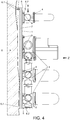
- each of the extension elements (6) arranged in the rear side (1.2) serve as support against the wall (8) onto which the present devices are fastened. Due to this goal of the ends of the extension elements (6), said extension elements (6) additionally comprise a support (6.1) at each of said ends, being the supports (6.1) clearly appreciated in Figures 2 and 3 .
- the supports (6.1) are aimed to increasing the contact surface between the extension elements (6) and the wall (8), apart from providing a support that does not damage or alter the contact surface between the extension elements (6) and the wall (8).
- the supports (6.1), in its most retracted position, are housed in the hollow or cavity generated by the step existing between the laminar body (1) and the profiles (7), not preventing the present device from being fastened or levelled should it not be required its extension or protuberance with respect to the laminar body (1), and the profiles (7), to level said device.
- extension elements (6) The main goal of these extension elements (6) is having an adjustable extension from their rear side (1.2), individually, to solve or compensate irregularities and/or inclination on the wall (8) area onto which the present device is fastened.
- An example is shown in Figure 3 wherein an inclination is compensated with respect to a vertical plane by means of a pair of extension elements (6) close to the profile (7) arranged on the upper edge. If the inclination is opposite to the one shown in Figure 3 , the device comprises the extension elements (6) closest to the lower edge of the device.
- the device may comprise some of the extension elements (6) close to the upper edge and other extension elements (6) close to the lower edge, maintaining the related ones in the retracted position, the supports close to the laminar body (1), and the related ones extended, that is with the supports (6.1) as far from the laminar body (1) as it is required.
- FIG 4 An example similar to the above-mentioned situation is shown in Figure 4 , where three out of the four supports (6.1) comprised in the device, are appreciated, each of them being extended at different extents according to the wall (8) requirements resulting from the irregularities thereon.
- the first step is to place the device in such a way that a screw or nail arranged in the wall (8) is arranged through the central orifice (2).
- the device simply hangs from said screw or nail, its position not being fastened. It is thus horizontally levelled, that is, a horizontal longitudinal axis that goes through the device through its centre with respect to the horizontal coordinate axis (X) is levelled.
- a level may be employed to facilitate said horizontal levelling.
- blind bores need to be carried out in the wall, using the lateral orifices (3) of the profile (7) to mark them on said wall.
- nails or screws are inserted to pre-fasten the device onto the wall (8) by partially inserting it in said wall (8).
- these nails or screws are not completely inserted, only insofar as it is necessary to maintain the device in horizontal position.
- the nails or screws located through the lateral orifices (3) fasten in a definite manner the position of the device by being introduced to the greatest extent possible according to the levelling and positioning established by the extension elements (6), that is to say by the levelling means (5, 6).
- the nails or screws may be inserted to the greatest extent possible according to the levelling and positioning established by the extension elements (6) for its definitive fastening.
- Additional elements may be used such as the level to arrange the device with the inclination or angle desired at any time during the fastening and levelling of the present device.
Landscapes
- Health & Medical Sciences (AREA)
- Life Sciences & Earth Sciences (AREA)
- Engineering & Computer Science (AREA)
- Hydrology & Water Resources (AREA)
- Public Health (AREA)
- Water Supply & Treatment (AREA)
- Finishing Walls (AREA)
- Legs For Furniture In General (AREA)
Claims (1)
- Vorrichtung zum Befestigen und Ausrichten von Sanitärarmaturen an Wänden (8), die umfasst:einen aus Schichten bestehenden Körper (1), der seinerseits umfasst:eine Vorderseite (1.1), die so angeordnet wird, dass sie den an dem aus Schichten bestehenden Körper (1) befestigten Sanitärarmaturen zugewandt ist; undeine Rückseite (1.2), die so angeordnet wird, dass sie der Wand (8) zugewandt ist;zwei Profile (7), die in den aus Schichten bestehenden Körper (1) integriert sind, d. h., entsprechend der Position der an der Wand (8) zu befestigenden Vorrichtung, eines an einer oberen Kante und ein anderes an einer unteren Kante des aus Schichten bestehenden Körpers (1), wobei beide Profile (7) an einer in Bezug auf den aus Schichten bestehenden Körper (1) zu der Rückseite (1.2) hin verschobenen Ebene angeordnet sind;Befestigungs-Öffnungen (2, 3) zum Befestigen der Vorrichtung an der Wand (8), wobei sie umfassen:eine mittige Öffnung (2), die an einem Mittelpunkt der Längsausdehnung des Profils (7) der oberen Kante angeordnet ist, sowieseitliche Öffnungen (3) wenigstens in dem Profil (7) der oberen und der unteren Kante;Ausricht-Einrichtungen (5, 6), die in dem aus Schichten bestehenden Körper (1) angeordnet sind und jeweils umfassen:einen mit Gewinde versehenen Körper (5) sowie ein Ausfahr-Element (6), das mit Außengewinde versehen ist und durch den mit Gewinde versehenen Körper (5) hindurch geschraubt werden kann,wobei die Vorrichtung dadurch gekennzeichnet ist, dass das Ausfahr-Element (6) durch eine damit verbundene Sicherungsmutter (6.3) fixiert wird, und das Ausfahr-Element (6) des Weiteren umfasst:eine Stütze (6.1) an einem Ende, die Beschädigung der Wand (8) vermeidet und Halt daran bietet, sowieeinen Kopf (6.2) an dem anderen Ende, der als ein Handhabungspunkt des Ausfahr-Elementes dient, das von dem Benutzer weiter oder weniger weit eingeschraubt wird, wobei der Kopf an der Vorderseite (1.1) angeordnet ist,so dass die Vorrichtung in Bezug auf die drei Koordinaten-Achsen (X, Y, Z) mittels der kombinierten Einstellung der Befestigungs-Öffnungen (2, 3) und der Ausricht-Einrichtungen (5, 6) befestigt und ausgerichtet wird, wobei die Befestigungs-Öffnungen (2, 3) und die Ausricht-Einrichtungen (5, 6) unabhängig voneinander gehandhabt werden, das Ausfahren jedes Ausfahr-Elementes (6) in Bezug auf die Rückseite (1.2) individuell eingestellt werden kann und Halt mit direktem Kontakt an der Wand (8) bietet.
Priority Applications (1)
| Application Number | Priority Date | Filing Date | Title |
|---|---|---|---|
| PL15192906T PL3040486T3 (pl) | 2014-12-30 | 2015-11-04 | Urządzenie do mocowania i poziomowania armatury sanitarnej na ścianach |
Applications Claiming Priority (1)
| Application Number | Priority Date | Filing Date | Title |
|---|---|---|---|
| ES201431695U ES1135619Y (es) | 2014-12-30 | 2014-12-30 | Dispositivo para fijación y nivelación de accesorios de saneamiento en paredes |
Publications (2)
| Publication Number | Publication Date |
|---|---|
| EP3040486A1 EP3040486A1 (de) | 2016-07-06 |
| EP3040486B1 true EP3040486B1 (de) | 2019-03-13 |
Family
ID=52389153
Family Applications (1)
| Application Number | Title | Priority Date | Filing Date |
|---|---|---|---|
| EP15192906.4A Not-in-force EP3040486B1 (de) | 2014-12-30 | 2015-11-04 | Vorrichtung zum befestigen und nivellieren von sanitärarmaturen auf wänden |
Country Status (3)
| Country | Link |
|---|---|
| EP (1) | EP3040486B1 (de) |
| ES (2) | ES1135619Y (de) |
| PL (1) | PL3040486T3 (de) |
Cited By (1)
| Publication number | Priority date | Publication date | Assignee | Title |
|---|---|---|---|---|
| RU222125U1 (ru) * | 2023-09-01 | 2023-12-12 | Дмитрий Владимирович Александров | Монтажная планка для водорозеток |
Families Citing this family (3)
| Publication number | Priority date | Publication date | Assignee | Title |
|---|---|---|---|---|
| DK179351B1 (en) * | 2016-07-12 | 2018-05-14 | Soendergaard Ebbe Schoedt | Adjustable Mounting Bracket |
| GR1009369B (el) * | 2017-05-11 | 2018-10-01 | Πανος Διονυσιου Τερζοπουλος | Βαση στηριξης εξαρτηματων υδρευσης με ενσωματωμενα αλφαδια ευθυγραμμισης |
| ES2697061B2 (es) * | 2017-07-21 | 2020-03-20 | Tor Mans S L | Dispositivo,sistema y procedimiento de posicionamiento para instalaciones hidraulicas en un paramento |
Family Cites Families (3)
| Publication number | Priority date | Publication date | Assignee | Title |
|---|---|---|---|---|
| ATE156216T1 (de) * | 1993-02-01 | 1997-08-15 | Mannesmann Ag | Vorrichtung zur befestigung von deckenwinkeln |
| DE102007055565B3 (de) * | 2007-11-20 | 2009-04-16 | Aloys F. Dornbracht Gmbh & Co. Kg | Vorrichtung zur Unterputzbefestigung von sanitären Elementen |
| DE102011082120B4 (de) * | 2011-09-05 | 2016-09-15 | Hansgrohe Se | Anschlussblock |
-
2014
- 2014-12-30 ES ES201431695U patent/ES1135619Y/es not_active Expired - Fee Related
-
2015
- 2015-11-04 PL PL15192906T patent/PL3040486T3/pl unknown
- 2015-11-04 ES ES15192906T patent/ES2721265T3/es active Active
- 2015-11-04 EP EP15192906.4A patent/EP3040486B1/de not_active Not-in-force
Non-Patent Citations (1)
| Title |
|---|
| None * |
Cited By (1)
| Publication number | Priority date | Publication date | Assignee | Title |
|---|---|---|---|---|
| RU222125U1 (ru) * | 2023-09-01 | 2023-12-12 | Дмитрий Владимирович Александров | Монтажная планка для водорозеток |
Also Published As
| Publication number | Publication date |
|---|---|
| EP3040486A1 (de) | 2016-07-06 |
| PL3040486T3 (pl) | 2019-09-30 |
| ES2721265T3 (es) | 2019-07-30 |
| ES1135619Y (es) | 2015-04-20 |
| ES1135619U (es) | 2015-01-28 |
Similar Documents
| Publication | Publication Date | Title |
|---|---|---|
| US8939416B2 (en) | Front adjustable wall panel mounting device | |
| EP3040486B1 (de) | Vorrichtung zum befestigen und nivellieren von sanitärarmaturen auf wänden | |
| US9668576B2 (en) | Cabinet hanging and aligning system and method | |
| US9687092B2 (en) | Picture frame wall hanging and leveling assembly | |
| US20160249471A1 (en) | Curvature-adjustable curved display device | |
| US20140306079A1 (en) | Fixing Plate | |
| US9844265B2 (en) | Adjustable television nook mount | |
| JP5681509B2 (ja) | 建具枠調整具及び建具枠調整構造 | |
| IT201600070881A1 (it) | Sistema di giunzione con livellatore per parti di mobili e articoli da arredamento | |
| KR101631689B1 (ko) | 복합 앵커 시스템 | |
| CN105452579A (zh) | 活动地板系统 | |
| RU147534U1 (ru) | Кронштейн крепежный | |
| CN103883855B (zh) | 壁挂组件 | |
| US20160160512A1 (en) | Primary and intermediate horizontal leveler | |
| KR101606330B1 (ko) | 거푸집 수평 조절장치 | |
| RU151327U1 (ru) | Кронштейн для установки рамных конструкций в проемы | |
| US20160177990A1 (en) | Coupling device and lamp apparatus having the same | |
| JP6560008B2 (ja) | 間仕切装置における上枠材の取付構造と、それを使用する間仕切装置 | |
| US20180100307A1 (en) | Adjustable lintel | |
| RU118672U1 (ru) | Кронштейн крепежный | |
| JP6158894B2 (ja) | コンクリート打設面の仕上げ方法とそれに用いる天端設定装置 | |
| KR101537083B1 (ko) | 흙손 | |
| RU147935U1 (ru) | Кронштейн крепежный | |
| KR20160101427A (ko) | 조적 벽체용 배전함 지지대 | |
| JP6156701B2 (ja) | 上端固定金物 |
Legal Events
| Date | Code | Title | Description |
|---|---|---|---|
| PUAI | Public reference made under article 153(3) epc to a published international application that has entered the european phase |
Free format text: ORIGINAL CODE: 0009012 |
|
| AK | Designated contracting states |
Kind code of ref document: A1 Designated state(s): AL AT BE BG CH CY CZ DE DK EE ES FI FR GB GR HR HU IE IS IT LI LT LU LV MC MK MT NL NO PL PT RO RS SE SI SK SM TR |
|
| AX | Request for extension of the european patent |
Extension state: BA ME |
|
| STAA | Information on the status of an ep patent application or granted ep patent |
Free format text: STATUS: REQUEST FOR EXAMINATION WAS MADE |
|
| 17P | Request for examination filed |
Effective date: 20161223 |
|
| RBV | Designated contracting states (corrected) |
Designated state(s): AL AT BE BG CH CY CZ DE DK EE ES FI FR GB GR HR HU IE IS IT LI LT LU LV MC MK MT NL NO PL PT RO RS SE SI SK SM TR |
|
| STAA | Information on the status of an ep patent application or granted ep patent |
Free format text: STATUS: EXAMINATION IS IN PROGRESS |
|
| 17Q | First examination report despatched |
Effective date: 20170628 |
|
| GRAP | Despatch of communication of intention to grant a patent |
Free format text: ORIGINAL CODE: EPIDOSNIGR1 |
|
| STAA | Information on the status of an ep patent application or granted ep patent |
Free format text: STATUS: GRANT OF PATENT IS INTENDED |
|
| INTG | Intention to grant announced |
Effective date: 20181205 |
|
| GRAS | Grant fee paid |
Free format text: ORIGINAL CODE: EPIDOSNIGR3 |
|
| GRAA | (expected) grant |
Free format text: ORIGINAL CODE: 0009210 |
|
| STAA | Information on the status of an ep patent application or granted ep patent |
Free format text: STATUS: THE PATENT HAS BEEN GRANTED |
|
| AK | Designated contracting states |
Kind code of ref document: B1 Designated state(s): AL AT BE BG CH CY CZ DE DK EE ES FI FR GB GR HR HU IE IS IT LI LT LU LV MC MK MT NL NO PL PT RO RS SE SI SK SM TR |
|
| REG | Reference to a national code |
Ref country code: GB Ref legal event code: FG4D |
|
| REG | Reference to a national code |
Ref country code: CH Ref legal event code: EP Ref country code: AT Ref legal event code: REF Ref document number: 1107842 Country of ref document: AT Kind code of ref document: T Effective date: 20190315 |
|
| REG | Reference to a national code |
Ref country code: IE Ref legal event code: FG4D |
|
| REG | Reference to a national code |
Ref country code: DE Ref legal event code: R096 Ref document number: 602015026225 Country of ref document: DE |
|
| REG | Reference to a national code |
Ref country code: NL Ref legal event code: MP Effective date: 20190313 |
|
| REG | Reference to a national code |
Ref country code: LT Ref legal event code: MG4D |
|
| REG | Reference to a national code |
Ref country code: ES Ref legal event code: FG2A Ref document number: 2721265 Country of ref document: ES Kind code of ref document: T3 Effective date: 20190730 |
|
| PG25 | Lapsed in a contracting state [announced via postgrant information from national office to epo] |
Ref country code: LT Free format text: LAPSE BECAUSE OF FAILURE TO SUBMIT A TRANSLATION OF THE DESCRIPTION OR TO PAY THE FEE WITHIN THE PRESCRIBED TIME-LIMIT Effective date: 20190313 Ref country code: FI Free format text: LAPSE BECAUSE OF FAILURE TO SUBMIT A TRANSLATION OF THE DESCRIPTION OR TO PAY THE FEE WITHIN THE PRESCRIBED TIME-LIMIT Effective date: 20190313 Ref country code: NO Free format text: LAPSE BECAUSE OF FAILURE TO SUBMIT A TRANSLATION OF THE DESCRIPTION OR TO PAY THE FEE WITHIN THE PRESCRIBED TIME-LIMIT Effective date: 20190613 Ref country code: SE Free format text: LAPSE BECAUSE OF FAILURE TO SUBMIT A TRANSLATION OF THE DESCRIPTION OR TO PAY THE FEE WITHIN THE PRESCRIBED TIME-LIMIT Effective date: 20190313 |
|
| PG25 | Lapsed in a contracting state [announced via postgrant information from national office to epo] |
Ref country code: LV Free format text: LAPSE BECAUSE OF FAILURE TO SUBMIT A TRANSLATION OF THE DESCRIPTION OR TO PAY THE FEE WITHIN THE PRESCRIBED TIME-LIMIT Effective date: 20190313 Ref country code: RS Free format text: LAPSE BECAUSE OF FAILURE TO SUBMIT A TRANSLATION OF THE DESCRIPTION OR TO PAY THE FEE WITHIN THE PRESCRIBED TIME-LIMIT Effective date: 20190313 Ref country code: GR Free format text: LAPSE BECAUSE OF FAILURE TO SUBMIT A TRANSLATION OF THE DESCRIPTION OR TO PAY THE FEE WITHIN THE PRESCRIBED TIME-LIMIT Effective date: 20190614 Ref country code: BG Free format text: LAPSE BECAUSE OF FAILURE TO SUBMIT A TRANSLATION OF THE DESCRIPTION OR TO PAY THE FEE WITHIN THE PRESCRIBED TIME-LIMIT Effective date: 20190613 Ref country code: HR Free format text: LAPSE BECAUSE OF FAILURE TO SUBMIT A TRANSLATION OF THE DESCRIPTION OR TO PAY THE FEE WITHIN THE PRESCRIBED TIME-LIMIT Effective date: 20190313 Ref country code: NL Free format text: LAPSE BECAUSE OF FAILURE TO SUBMIT A TRANSLATION OF THE DESCRIPTION OR TO PAY THE FEE WITHIN THE PRESCRIBED TIME-LIMIT Effective date: 20190313 |
|
| REG | Reference to a national code |
Ref country code: AT Ref legal event code: MK05 Ref document number: 1107842 Country of ref document: AT Kind code of ref document: T Effective date: 20190313 |
|
| PG25 | Lapsed in a contracting state [announced via postgrant information from national office to epo] |
Ref country code: PT Free format text: LAPSE BECAUSE OF FAILURE TO SUBMIT A TRANSLATION OF THE DESCRIPTION OR TO PAY THE FEE WITHIN THE PRESCRIBED TIME-LIMIT Effective date: 20190713 Ref country code: AL Free format text: LAPSE BECAUSE OF FAILURE TO SUBMIT A TRANSLATION OF THE DESCRIPTION OR TO PAY THE FEE WITHIN THE PRESCRIBED TIME-LIMIT Effective date: 20190313 Ref country code: SK Free format text: LAPSE BECAUSE OF FAILURE TO SUBMIT A TRANSLATION OF THE DESCRIPTION OR TO PAY THE FEE WITHIN THE PRESCRIBED TIME-LIMIT Effective date: 20190313 Ref country code: CZ Free format text: LAPSE BECAUSE OF FAILURE TO SUBMIT A TRANSLATION OF THE DESCRIPTION OR TO PAY THE FEE WITHIN THE PRESCRIBED TIME-LIMIT Effective date: 20190313 Ref country code: RO Free format text: LAPSE BECAUSE OF FAILURE TO SUBMIT A TRANSLATION OF THE DESCRIPTION OR TO PAY THE FEE WITHIN THE PRESCRIBED TIME-LIMIT Effective date: 20190313 Ref country code: EE Free format text: LAPSE BECAUSE OF FAILURE TO SUBMIT A TRANSLATION OF THE DESCRIPTION OR TO PAY THE FEE WITHIN THE PRESCRIBED TIME-LIMIT Effective date: 20190313 |
|
| PG25 | Lapsed in a contracting state [announced via postgrant information from national office to epo] |
Ref country code: SM Free format text: LAPSE BECAUSE OF FAILURE TO SUBMIT A TRANSLATION OF THE DESCRIPTION OR TO PAY THE FEE WITHIN THE PRESCRIBED TIME-LIMIT Effective date: 20190313 |
|
| REG | Reference to a national code |
Ref country code: DE Ref legal event code: R097 Ref document number: 602015026225 Country of ref document: DE |
|
| PG25 | Lapsed in a contracting state [announced via postgrant information from national office to epo] |
Ref country code: IS Free format text: LAPSE BECAUSE OF FAILURE TO SUBMIT A TRANSLATION OF THE DESCRIPTION OR TO PAY THE FEE WITHIN THE PRESCRIBED TIME-LIMIT Effective date: 20190713 Ref country code: AT Free format text: LAPSE BECAUSE OF FAILURE TO SUBMIT A TRANSLATION OF THE DESCRIPTION OR TO PAY THE FEE WITHIN THE PRESCRIBED TIME-LIMIT Effective date: 20190313 |
|
| PLBE | No opposition filed within time limit |
Free format text: ORIGINAL CODE: 0009261 |
|
| STAA | Information on the status of an ep patent application or granted ep patent |
Free format text: STATUS: NO OPPOSITION FILED WITHIN TIME LIMIT |
|
| PG25 | Lapsed in a contracting state [announced via postgrant information from national office to epo] |
Ref country code: DK Free format text: LAPSE BECAUSE OF FAILURE TO SUBMIT A TRANSLATION OF THE DESCRIPTION OR TO PAY THE FEE WITHIN THE PRESCRIBED TIME-LIMIT Effective date: 20190313 |
|
| 26N | No opposition filed |
Effective date: 20191216 |
|
| PG25 | Lapsed in a contracting state [announced via postgrant information from national office to epo] |
Ref country code: SI Free format text: LAPSE BECAUSE OF FAILURE TO SUBMIT A TRANSLATION OF THE DESCRIPTION OR TO PAY THE FEE WITHIN THE PRESCRIBED TIME-LIMIT Effective date: 20190313 |
|
| PG25 | Lapsed in a contracting state [announced via postgrant information from national office to epo] |
Ref country code: TR Free format text: LAPSE BECAUSE OF FAILURE TO SUBMIT A TRANSLATION OF THE DESCRIPTION OR TO PAY THE FEE WITHIN THE PRESCRIBED TIME-LIMIT Effective date: 20190313 |
|
| REG | Reference to a national code |
Ref country code: CH Ref legal event code: PL |
|
| PG25 | Lapsed in a contracting state [announced via postgrant information from national office to epo] |
Ref country code: LU Free format text: LAPSE BECAUSE OF NON-PAYMENT OF DUE FEES Effective date: 20191104 Ref country code: CH Free format text: LAPSE BECAUSE OF NON-PAYMENT OF DUE FEES Effective date: 20191130 Ref country code: LI Free format text: LAPSE BECAUSE OF NON-PAYMENT OF DUE FEES Effective date: 20191130 Ref country code: MC Free format text: LAPSE BECAUSE OF FAILURE TO SUBMIT A TRANSLATION OF THE DESCRIPTION OR TO PAY THE FEE WITHIN THE PRESCRIBED TIME-LIMIT Effective date: 20190313 |
|
| REG | Reference to a national code |
Ref country code: BE Ref legal event code: MM Effective date: 20191130 |
|
| GBPC | Gb: european patent ceased through non-payment of renewal fee |
Effective date: 20191104 |
|
| PG25 | Lapsed in a contracting state [announced via postgrant information from national office to epo] |
Ref country code: IE Free format text: LAPSE BECAUSE OF NON-PAYMENT OF DUE FEES Effective date: 20191104 Ref country code: GB Free format text: LAPSE BECAUSE OF NON-PAYMENT OF DUE FEES Effective date: 20191104 |
|
| PGFP | Annual fee paid to national office [announced via postgrant information from national office to epo] |
Ref country code: FR Payment date: 20200915 Year of fee payment: 6 |
|
| PG25 | Lapsed in a contracting state [announced via postgrant information from national office to epo] |
Ref country code: BE Free format text: LAPSE BECAUSE OF NON-PAYMENT OF DUE FEES Effective date: 20191130 |
|
| PGFP | Annual fee paid to national office [announced via postgrant information from national office to epo] |
Ref country code: ES Payment date: 20201201 Year of fee payment: 6 Ref country code: IT Payment date: 20201111 Year of fee payment: 6 Ref country code: DE Payment date: 20201126 Year of fee payment: 6 |
|
| PGFP | Annual fee paid to national office [announced via postgrant information from national office to epo] |
Ref country code: PL Payment date: 20201009 Year of fee payment: 6 |
|
| PG25 | Lapsed in a contracting state [announced via postgrant information from national office to epo] |
Ref country code: CY Free format text: LAPSE BECAUSE OF FAILURE TO SUBMIT A TRANSLATION OF THE DESCRIPTION OR TO PAY THE FEE WITHIN THE PRESCRIBED TIME-LIMIT Effective date: 20190313 |
|
| PG25 | Lapsed in a contracting state [announced via postgrant information from national office to epo] |
Ref country code: MT Free format text: LAPSE BECAUSE OF FAILURE TO SUBMIT A TRANSLATION OF THE DESCRIPTION OR TO PAY THE FEE WITHIN THE PRESCRIBED TIME-LIMIT Effective date: 20190313 Ref country code: HU Free format text: LAPSE BECAUSE OF FAILURE TO SUBMIT A TRANSLATION OF THE DESCRIPTION OR TO PAY THE FEE WITHIN THE PRESCRIBED TIME-LIMIT; INVALID AB INITIO Effective date: 20151104 |
|
| REG | Reference to a national code |
Ref country code: DE Ref legal event code: R119 Ref document number: 602015026225 Country of ref document: DE |
|
| PG25 | Lapsed in a contracting state [announced via postgrant information from national office to epo] |
Ref country code: MK Free format text: LAPSE BECAUSE OF FAILURE TO SUBMIT A TRANSLATION OF THE DESCRIPTION OR TO PAY THE FEE WITHIN THE PRESCRIBED TIME-LIMIT Effective date: 20190313 |
|
| PG25 | Lapsed in a contracting state [announced via postgrant information from national office to epo] |
Ref country code: DE Free format text: LAPSE BECAUSE OF NON-PAYMENT OF DUE FEES Effective date: 20220601 |
|
| PG25 | Lapsed in a contracting state [announced via postgrant information from national office to epo] |
Ref country code: FR Free format text: LAPSE BECAUSE OF NON-PAYMENT OF DUE FEES Effective date: 20211130 |
|
| PG25 | Lapsed in a contracting state [announced via postgrant information from national office to epo] |
Ref country code: IT Free format text: LAPSE BECAUSE OF NON-PAYMENT OF DUE FEES Effective date: 20211104 |
|
| REG | Reference to a national code |
Ref country code: ES Ref legal event code: FD2A Effective date: 20230214 |
|
| PG25 | Lapsed in a contracting state [announced via postgrant information from national office to epo] |
Ref country code: ES Free format text: LAPSE BECAUSE OF NON-PAYMENT OF DUE FEES Effective date: 20211105 |
|
| PG25 | Lapsed in a contracting state [announced via postgrant information from national office to epo] |
Ref country code: PL Free format text: LAPSE BECAUSE OF NON-PAYMENT OF DUE FEES Effective date: 20211104 |