EP3040485A2 - Verschleissanordnung für erdförderungsmaschine - Google Patents
Verschleissanordnung für erdförderungsmaschine Download PDFInfo
- Publication number
- EP3040485A2 EP3040485A2 EP15197043.1A EP15197043A EP3040485A2 EP 3040485 A2 EP3040485 A2 EP 3040485A2 EP 15197043 A EP15197043 A EP 15197043A EP 3040485 A2 EP3040485 A2 EP 3040485A2
- Authority
- EP
- European Patent Office
- Prior art keywords
- pin
- blocking
- blocking element
- assembly according
- adapter
- Prior art date
- Legal status (The legal status is an assumption and is not a legal conclusion. Google has not performed a legal analysis and makes no representation as to the accuracy of the status listed.)
- Granted
Links
Images


Classifications
-
- E—FIXED CONSTRUCTIONS
- E02—HYDRAULIC ENGINEERING; FOUNDATIONS; SOIL SHIFTING
- E02F—DREDGING; SOIL-SHIFTING
- E02F9/00—Component parts of dredgers or soil-shifting machines, not restricted to one of the kinds covered by groups E02F3/00 - E02F7/00
- E02F9/28—Small metalwork for digging elements, e.g. teeth scraper bits
- E02F9/2808—Teeth
- E02F9/2816—Mountings therefor
- E02F9/2833—Retaining means, e.g. pins
- E02F9/2841—Retaining means, e.g. pins resilient
-
- E—FIXED CONSTRUCTIONS
- E02—HYDRAULIC ENGINEERING; FOUNDATIONS; SOIL SHIFTING
- E02F—DREDGING; SOIL-SHIFTING
- E02F9/00—Component parts of dredgers or soil-shifting machines, not restricted to one of the kinds covered by groups E02F3/00 - E02F7/00
- E02F9/28—Small metalwork for digging elements, e.g. teeth scraper bits
- E02F9/2808—Teeth
- E02F9/2816—Mountings therefor
- E02F9/2833—Retaining means, e.g. pins
-
- E—FIXED CONSTRUCTIONS
- E02—HYDRAULIC ENGINEERING; FOUNDATIONS; SOIL SHIFTING
- E02F—DREDGING; SOIL-SHIFTING
- E02F9/00—Component parts of dredgers or soil-shifting machines, not restricted to one of the kinds covered by groups E02F3/00 - E02F7/00
- E02F9/28—Small metalwork for digging elements, e.g. teeth scraper bits
- E02F9/2808—Teeth
- E02F9/285—Teeth characterised by the material used
Definitions
- This invention relates to a wear assembly for an earth moving machine.
- the adapters are internal components that are stably connected to the aforesaid machinery (for example by welding), and are covered and protected by the wear teeth that, on the contrary, are expendable components, intended to undergo a massive wear in place of the adapters and buckets.
- This invention fits in the previous context, proposing to provide a wear assembly with faster fastening than traditional systems while suitable to be released with a few simple operations and designed to be mass-produced at low cost.
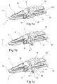
- reference number 1 identifies, in its totality, a wear assembly comprising a wear tooth 2, an adapter 10 and a blocking pin 16 between the wear tooth 2 and the adapter 10.
- the wear tooth 2 comprises a body wall 4 that delimits at least part of a tip pocket 6, preferably open backwardly, and at least a through hole 8, 8' communicating with said pocket.
- the wear tooth 2 comprises an upper wall 46 and a lower tooth wall 48 that converge frontally to form a working portion 72, for example an excavation tip or edge.
- the working portion 72 could have any shape (for example bifurcated, pointed, flattened, etc.) depending on the purpose or use of the wear tooth.
- front will indicate all those components facing or turned towards the working portion; on the contrary, the term “rear” will refer to a direction opposite the working portion, which is to say towards the adapter 10 or to a grab bucket 50 of the earth moving machine connected to the latter.
- connection point is generally or substantially truncated-pyramidal.
- the body wall 4 extends in tubular or conical manner around a longitudinal tooth axis Y.
- the body wall 4 delimits at least a pair of through holes 8, 8', for example aligned to each other.
- the adapter 10 comprises a connection point 12, at least partially inserted in the tip pocket 6, in a removable manner, and that defines a pin cavity 14 at least partially aligned with the through hole 8, 8' or to the pair of such holes.
- the pin cavity 14 thus constitutes the seat of the adapter in which the blocking pin 16 is at least partially received.
- the pin cavity 14 is at least partially aligned and communicating with the pair of through holes 8, 8', when provided.
- connection point 12 thus performs the adapter-tooth connection by geometrically coupling to the tip pocket 6.
- inner surfaces 52, 54 of the wear tooth 2 lie in abutment with the corresponding outer surfaces 56, 58 of the connection point 12.
- connection point 12 is crossed (preferably from side to side) by the pin cavity 14.
- the adapter 10 is associable to the grab bucket 50 of an earth moving machine (not shown) by means of fastening stems 60, 62 that define between them a space 64 for the rear insertion of the aforesaid bucket.
- the fastening stems are suitable to engage the grab bucket 50 to be subsequently secured to it, for example by welding.
- the blocking pin 16 is inserted in the through hole 8, 8' and in the pin cavity 14 rotatably around a rotation axis R and comprises at least a first blocking element 18.
- the rotation axis R extends in a manner incident or orthogonal with respect to the longitudinal tooth axis Y.
- the blocking pin 16 extends along a development direction X, specifically between a pin head 38 and an opposite pin tip 40.
- the development direction X is substantially parallel or coincident to the rotation axis R.
- the pin head 38 and the opposite pin tip 40 are both accessible through the said holes.
- the pin head 38 delimits a polygonal recess 42 (for example hexagonal) and/or the pin tip 40 is shaped externally 44 in a polygonal manner (for example hexagonal), to act in conjunction with one or more tools counter-shaped to said polygonal areas.
- a polygonal recess 42 for example hexagonal
- the pin tip 40 is shaped externally 44 in a polygonal manner (for example hexagonal), to act in conjunction with one or more tools counter-shaped to said polygonal areas.
- the pin head 38 and/or the pin tip 40 can be actuated by means of a tool to cause rotation of the blocking pin in the through hole and in the cavity pin as previously discussed.
- the pin tip may define a polygonal recess and/or the pin head could be shaped externally in a polygonal manner, in an arrangement opposite to that mentioned above.
- the pin head 38 could be inserted at least in part (for example completely) in the through hole 8, 8'.
- the wear assembly 1 may comprise a protective hood (not shown) coupled with the pin head and/or with the surfaces delimiting the through hole 8, 8' to close at least partially the space surrounding the pin head 38.
- the protective hood may delimit a guide for the insertion of a tool (for example a screwdriver) to move it away from the pin head 38.
- a tool for example a screwdriver
- the wear assembly 1 comprises at least a second blocking element 20, 20' associated to the wear tooth 2 or to the adapter 10.
- the second blocking element 20, 20' is connected to the adapter 10, for example in correspondence of an outer surface or side 66 of such adapter.
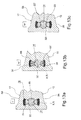
- the second blocking element 20, 20' is inserted in a seat 28 of the wear tooth 2, advantageously facing the tip pocket 6 ( figure 12a ).
- the blocking elements 18, 20, 20' are mutually arranged in such a way that, through rotation of the blocking pin 16 in a certain direction (clockwise or counter-clockwise), the first blocking element 18 intercepts the second blocking element 20, 20' to block said pin in the pin cavity 14.
- the first blocking element 18 arrives in abutment against the second blocking element 20, 20' to block the blocking pin 16 in the pin cavity 14.
- one of the aforesaid elements 20, 20' is deformable so that, through a further rotation of the blocking pin 16 in the same direction (clockwise or counter-clockwise), this element disengages from the other element 18, thus allowing the extraction of the blocking pin from the pin cavity 14.
- one of the aforesaid elements 20, 20' is compressible to accomplish the aforesaid disengagement.
- this does not prevent that the disengagement of the blocking elements 18, 20, 20' could also take place by changing the direction of rotation of the blocking pin (for example from clockwise to counter-clockwise), by performing in reverse the rotation movement that led to the aforesaid engagement.
- the deformable blocking element (first 18 or second 20, 20') has a shape memory.
- the deformable blocking element 20, 20' is associated to the wear tooth 2 or to the adapter 10.
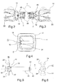
- figures 10 and 11 illustrate second, non-deformed blocking elements, while figure 8 shows these elements in contact with the first blocking element 18.
- the second blocking element 20, 20' is at least partially (or completely) made of a first resilient material 24, configured to deform as a result of said rotation of the blocking pin 16.
- a plurality of first blocking elements 18 is provided, angularly staggered around the blocking pin 16, interacting with one or more second blocking elements 20, 20'.
- the wear assembly could comprise a single second blocking element 20 ( figure 11 ).
- the wear assembly could comprise a plurality of second blocking elements 20, 20' ( figure 10 ), for example acting along incident or (diametrically) opposite directions.
- first blocking elements 18 and the at least one second blocking element 20, 20' extend for a portion parallel to the rotation axis R.
- these first elements are alongside the second element so as to guide the blocking pin 16 into or out of the pin cavity 14.
- the first blocking elements 18 delimit between them a sliding passage 70 along which, at least during insertion of the blocking pin in the pin cavity, the second blocking element 20 is slidably received at least in part.
- a pair of second blocking elements could extend for a portion parallel to the rotation axis R and such pair could accompany the first blocking element so as to guide the blocking pin 16 into or out of the pin cavity 14.
- the second blocking element 20, 20' comprises at least one element end 22, 22' projecting into the lumen of the through hole 8, 8' and/or of the pin cavity 14 to intercept the blocking pin 16 and, in particular, the first blocking element 18.
- the second blocking element 20, 20' could comprise an attachment portion 26 to a seat 28 of the wear tooth 2 or adapter 10.
- this portion 26 could comprise a second resilient material 30 configured to block itself by force and, optionally also by shape, in said seat.
- the second resilient material 30 is a material different from the first resilient material 24, at least for the related mechanical behaviour (for example, the related modulus of elasticity).
- the first resilient material 24 and the second resilient material 30 are co- or over-moulded.
- the first blocking element 18 could comprise at least one lateral protrusion 32, which extends radially with respect to the direction of extension X of the blocking pin 16, to stop the rotation of the latter around the rotation axis R and to block the translation of said pin parallel to said axis R.
- the first blocking element 18 comprises at least one pair of lateral protrusions 32 separated from each other.
- the first blocking element 18 further comprises at least one projection or annular lip 34 that, with the aforesaid protrusions 32 defines a recess 36 for receiving at least part of the second blocking element 20, 20'.
- the projection or annular lip 34 improves the resistance to the extraction of the blocking pin from the pin cavity of the adapter 10.
- this second blocking element is enclosed (axially) between the pin head 38 and the projection or annular lip 34.
- This invention further relates to a wear assembly 1, comprising:
- this invention relates to an earth moving machine comprising at least one wear assembly 1, according to any of the preceding embodiments, connected to a grab bucket 50 by means of the respective adapter 10.
- the aforesaid assembly is simple to construct and allows a very rapid assembly and disassembly compared to traditional systems.
- the assembly covered by this invention allows optimising the use of the mechanical components and facilitating their renewal or replacement.
- the assembly covered by this invention allows giving up the use of hammers for blocking of the tooth, and in this way, risks for the operator who must perform the aforesaid assembly are minimised.
- the useful life of the assembly described is dramatically longer than the devices of the prior art, particularly by virtue of the reduced play between the components.
- the blocking pins described are suitable to eliminate any play in the receiving pocket, so as to give a sense of stability when assembly is concluded.
- the assembly covered by this invention ensures a complete, safe and efficient coupling between tooth and adapter.
- the operator actuating the blocking pin does not need to remember the direction of rotation for blocking or unblocking said pin since, preferably, the blocking and unblocking of the pin are repeated cyclically in any chosen direction of rotation.
- the assembly covered by this invention is, above all, a highly reliable system since the contact surfaces between the parts are large and allow a better distribution of the stresses.
- the solution with a reduced number of blocking organs while maintaining all the advantages discussed, will also have a further advantage in terms of costs to be incurred by the user as there is one mechanical part less for the completion of the coupling.
- each of the variants described as belonging to a possible embodiment can be performed independently of the other variants described.
Landscapes
- Engineering & Computer Science (AREA)
- Mining & Mineral Resources (AREA)
- Civil Engineering (AREA)
- General Engineering & Computer Science (AREA)
- Structural Engineering (AREA)
- Component Parts Of Construction Machinery (AREA)
Applications Claiming Priority (1)
| Application Number | Priority Date | Filing Date | Title |
|---|---|---|---|
| ITBG20140061 | 2014-12-30 |
Publications (3)
| Publication Number | Publication Date |
|---|---|
| EP3040485A2 true EP3040485A2 (de) | 2016-07-06 |
| EP3040485A3 EP3040485A3 (de) | 2016-10-19 |
| EP3040485B1 EP3040485B1 (de) | 2018-07-25 |
Family
ID=52633340
Family Applications (1)
| Application Number | Title | Priority Date | Filing Date |
|---|---|---|---|
| EP15197043.1A Active EP3040485B1 (de) | 2014-12-30 | 2015-11-30 | Verschleissanordnung für erdförderungsmaschine |
Country Status (4)
| Country | Link |
|---|---|
| EP (1) | EP3040485B1 (de) |
| DK (1) | DK3040485T3 (de) |
| ES (1) | ES2692403T3 (de) |
| PT (1) | PT3040485T (de) |
Cited By (6)
| Publication number | Priority date | Publication date | Assignee | Title |
|---|---|---|---|---|
| AU2018264144A1 (en) * | 2017-12-29 | 2019-07-18 | Sungbo Industrial Co., Ltd. | Bucket tooth of excavator |
| CN110847276A (zh) * | 2019-10-30 | 2020-02-28 | 宁波禾顺新材料有限公司 | 一种连接限位结构及用于挖掘设备的耐磨组件 |
| CN113227507A (zh) * | 2018-12-12 | 2021-08-06 | 成矿研究科技有限公司 | 土方机械中力的测量和控制系统和方法,及自动或半自动机械 |
| CN113293817A (zh) * | 2021-05-20 | 2021-08-24 | 漳州鑫山航机械有限公司 | 拆卸及安装斗齿销轴的液压设备 |
| US20220002982A1 (en) * | 2020-07-06 | 2022-01-06 | Caterpillar Inc. | Retention system for boltless cutting edges |
| EP4600431A3 (de) * | 2019-04-15 | 2025-12-03 | Hensley Industries, Inc. | Positionsvorgespannte verriegelungsstiftanordnung für ein bodeneingriffsverschleisselement |
Family Cites Families (6)
| Publication number | Priority date | Publication date | Assignee | Title |
|---|---|---|---|---|
| US5435084A (en) * | 1994-02-17 | 1995-07-25 | Harnischfeger Corporation | Apparatus and method for attaching a digging tooth tip |
| PE20130327A1 (es) * | 2009-12-11 | 2013-04-03 | Cqms Pty Ltd | Pieza de fijacion para un consumible de excavadora |
| AU2012307065B2 (en) * | 2011-09-08 | 2017-10-26 | Cqms Razer Pty Ltd | A lock assembly for an excavator wear member |
| CA2805398A1 (en) * | 2013-02-08 | 2014-08-08 | Quality Chain Canada Ulc | Bucket tooth locking pin |
| US9388553B2 (en) * | 2013-05-31 | 2016-07-12 | Caterpillar Inc. | Retainer systems for ground engaging tools |
| US8807901B1 (en) * | 2013-10-10 | 2014-08-19 | Pasquale Lombardo | Universal hammerless pin assembly |
-
2015
- 2015-11-30 EP EP15197043.1A patent/EP3040485B1/de active Active
- 2015-11-30 PT PT15197043T patent/PT3040485T/pt unknown
- 2015-11-30 DK DK15197043.1T patent/DK3040485T3/en active
- 2015-11-30 ES ES15197043.1T patent/ES2692403T3/es active Active
Non-Patent Citations (1)
| Title |
|---|
| None |
Cited By (10)
| Publication number | Priority date | Publication date | Assignee | Title |
|---|---|---|---|---|
| AU2018264144A1 (en) * | 2017-12-29 | 2019-07-18 | Sungbo Industrial Co., Ltd. | Bucket tooth of excavator |
| AU2018264144B2 (en) * | 2017-12-29 | 2020-07-02 | Sungbo Industrial Co., Ltd. | Bucket tooth of excavator |
| US10954656B2 (en) | 2017-12-29 | 2021-03-23 | Sungbo Industrial Co., Ltd. | Bucket tooth of excavator |
| CN113227507A (zh) * | 2018-12-12 | 2021-08-06 | 成矿研究科技有限公司 | 土方机械中力的测量和控制系统和方法,及自动或半自动机械 |
| US12325984B2 (en) | 2018-12-12 | 2025-06-10 | Metalogenia Research & Technologies, S.L. | Systems and methods for measuring forces in earth moving machinery and control thereof, and automatic or semi-automatic machinery |
| EP4600431A3 (de) * | 2019-04-15 | 2025-12-03 | Hensley Industries, Inc. | Positionsvorgespannte verriegelungsstiftanordnung für ein bodeneingriffsverschleisselement |
| CN110847276A (zh) * | 2019-10-30 | 2020-02-28 | 宁波禾顺新材料有限公司 | 一种连接限位结构及用于挖掘设备的耐磨组件 |
| US20220002982A1 (en) * | 2020-07-06 | 2022-01-06 | Caterpillar Inc. | Retention system for boltless cutting edges |
| US11970842B2 (en) * | 2020-07-06 | 2024-04-30 | Caterpillar Inc. | Retention system for boltless cutting edges |
| CN113293817A (zh) * | 2021-05-20 | 2021-08-24 | 漳州鑫山航机械有限公司 | 拆卸及安装斗齿销轴的液压设备 |
Also Published As
| Publication number | Publication date |
|---|---|
| EP3040485B1 (de) | 2018-07-25 |
| DK3040485T3 (en) | 2018-10-29 |
| EP3040485A3 (de) | 2016-10-19 |
| PT3040485T (pt) | 2018-11-07 |
| ES2692403T3 (es) | 2018-12-03 |
Similar Documents
| Publication | Publication Date | Title |
|---|---|---|
| EP3040485B1 (de) | Verschleissanordnung für erdförderungsmaschine | |
| ES2445641T3 (es) | Sistema de herramientas de ataque al suelo | |
| EP2466015B1 (de) | Befestigungskupplung für schweres gerät | |
| RU2607814C2 (ru) | Устройство для защиты кромки узла землеройного орудия (варианты) | |
| KR102163088B1 (ko) | 잠금 핀 조립체를 갖는 굴착용 치형부 조립체 | |
| US20160222634A1 (en) | Device for securing teeth to tooth adapters of an earth-moving machine through pins | |
| KR102246372B1 (ko) | 마모부와 그것의 지지체 사이의 연결 장치를 포함하는 기계 시스템, 및 건설 중장비의 버킷 | |
| CN102272386A (zh) | 作业工具联结机构 | |
| EP3052707B1 (de) | Kopplervorrichtung | |
| ES2749173T3 (es) | Conector para facilitar la elevación de piezas de desgaste | |
| CN104047953B (zh) | 销保持系统及组装销保持系统的方法 | |
| US9057176B2 (en) | Retention system for a ground-engaging tool | |
| US20160251820A1 (en) | Work tool assembly and coupler | |
| US12049910B2 (en) | Filter retaining plug | |
| CN107201756B (zh) | 用于器具组件的联接件 | |
| US9784292B1 (en) | Pin assembly for a piston of a hydraulic cylinder | |
| CZ2004205A3 (cs) | Nářadí pro dům a zahradu | |
| EP3604836B1 (de) | Ringförmiges drehschutzelement und druckluftbetriebener meissel | |
| ATE481595T1 (de) | Metallkupplung mit sperrposition |
Legal Events
| Date | Code | Title | Description |
|---|---|---|---|
| PUAI | Public reference made under article 153(3) epc to a published international application that has entered the european phase |
Free format text: ORIGINAL CODE: 0009012 |
|
| AK | Designated contracting states |
Kind code of ref document: A2 Designated state(s): AL AT BE BG CH CY CZ DE DK EE ES FI FR GB GR HR HU IE IS IT LI LT LU LV MC MK MT NL NO PL PT RO RS SE SI SK SM TR |
|
| AX | Request for extension of the european patent |
Extension state: BA ME |
|
| PUAL | Search report despatched |
Free format text: ORIGINAL CODE: 0009013 |
|
| AK | Designated contracting states |
Kind code of ref document: A3 Designated state(s): AL AT BE BG CH CY CZ DE DK EE ES FI FR GB GR HR HU IE IS IT LI LT LU LV MC MK MT NL NO PL PT RO RS SE SI SK SM TR |
|
| AX | Request for extension of the european patent |
Extension state: BA ME |
|
| RIC1 | Information provided on ipc code assigned before grant |
Ipc: E02F 9/28 20060101AFI20160912BHEP |
|
| 17P | Request for examination filed |
Effective date: 20170414 |
|
| RAV | Requested validation state of the european patent: fee paid |
Extension state: MA Effective date: 20170414 Extension state: MD Effective date: 20170414 |
|
| RAX | Requested extension states of the european patent have changed |
Extension state: BA Payment date: 20170414 Extension state: ME Payment date: 20170414 |
|
| RBV | Designated contracting states (corrected) |
Designated state(s): AL AT BE BG CH CY CZ DE DK EE ES FI FR GB GR HR HU IE IS IT LI LT LU LV MC MK MT NL NO PL PT RO RS SE SI SK SM TR |
|
| GRAP | Despatch of communication of intention to grant a patent |
Free format text: ORIGINAL CODE: EPIDOSNIGR1 |
|
| INTG | Intention to grant announced |
Effective date: 20180315 |
|
| RIN1 | Information on inventor provided before grant (corrected) |
Inventor name: CRISTOFORI, GIULIA |
|
| GRAS | Grant fee paid |
Free format text: ORIGINAL CODE: EPIDOSNIGR3 |
|
| GRAA | (expected) grant |
Free format text: ORIGINAL CODE: 0009210 |
|
| AK | Designated contracting states |
Kind code of ref document: B1 Designated state(s): AL AT BE BG CH CY CZ DE DK EE ES FI FR GB GR HR HU IE IS IT LI LT LU LV MC MK MT NL NO PL PT RO RS SE SI SK SM TR |
|
| AX | Request for extension of the european patent |
Extension state: BA ME |
|
| REG | Reference to a national code |
Ref country code: GB Ref legal event code: FG4D |
|
| REG | Reference to a national code |
Ref country code: CH Ref legal event code: EP |
|
| REG | Reference to a national code |
Ref country code: AT Ref legal event code: REF Ref document number: 1021908 Country of ref document: AT Kind code of ref document: T Effective date: 20180815 |
|
| REG | Reference to a national code |
Ref country code: IE Ref legal event code: FG4D |
|
| REG | Reference to a national code |
Ref country code: DE Ref legal event code: R096 Ref document number: 602015013934 Country of ref document: DE |
|
| REG | Reference to a national code |
Ref country code: NL Ref legal event code: FP |
|
| REG | Reference to a national code |
Ref country code: DK Ref legal event code: T3 Effective date: 20181016 |
|
| REG | Reference to a national code |
Ref country code: SE Ref legal event code: TRGR |
|
| REG | Reference to a national code |
Ref country code: PT Ref legal event code: SC4A Ref document number: 3040485 Country of ref document: PT Date of ref document: 20181107 Kind code of ref document: T Free format text: AVAILABILITY OF NATIONAL TRANSLATION Effective date: 20181011 |
|
| REG | Reference to a national code |
Ref country code: ES Ref legal event code: FG2A Ref document number: 2692403 Country of ref document: ES Kind code of ref document: T3 Effective date: 20181203 |
|
| REG | Reference to a national code |
Ref country code: LT Ref legal event code: MG4D |
|
| REG | Reference to a national code |
Ref country code: AT Ref legal event code: MK05 Ref document number: 1021908 Country of ref document: AT Kind code of ref document: T Effective date: 20180725 |
|
| PG25 | Lapsed in a contracting state [announced via postgrant information from national office to epo] |
Ref country code: AT Free format text: LAPSE BECAUSE OF FAILURE TO SUBMIT A TRANSLATION OF THE DESCRIPTION OR TO PAY THE FEE WITHIN THE PRESCRIBED TIME-LIMIT Effective date: 20180725 Ref country code: BG Free format text: LAPSE BECAUSE OF FAILURE TO SUBMIT A TRANSLATION OF THE DESCRIPTION OR TO PAY THE FEE WITHIN THE PRESCRIBED TIME-LIMIT Effective date: 20181025 Ref country code: IS Free format text: LAPSE BECAUSE OF FAILURE TO SUBMIT A TRANSLATION OF THE DESCRIPTION OR TO PAY THE FEE WITHIN THE PRESCRIBED TIME-LIMIT Effective date: 20181125 Ref country code: PL Free format text: LAPSE BECAUSE OF FAILURE TO SUBMIT A TRANSLATION OF THE DESCRIPTION OR TO PAY THE FEE WITHIN THE PRESCRIBED TIME-LIMIT Effective date: 20180725 Ref country code: RS Free format text: LAPSE BECAUSE OF FAILURE TO SUBMIT A TRANSLATION OF THE DESCRIPTION OR TO PAY THE FEE WITHIN THE PRESCRIBED TIME-LIMIT Effective date: 20180725 Ref country code: LT Free format text: LAPSE BECAUSE OF FAILURE TO SUBMIT A TRANSLATION OF THE DESCRIPTION OR TO PAY THE FEE WITHIN THE PRESCRIBED TIME-LIMIT Effective date: 20180725 Ref country code: FI Free format text: LAPSE BECAUSE OF FAILURE TO SUBMIT A TRANSLATION OF THE DESCRIPTION OR TO PAY THE FEE WITHIN THE PRESCRIBED TIME-LIMIT Effective date: 20180725 Ref country code: GR Free format text: LAPSE BECAUSE OF FAILURE TO SUBMIT A TRANSLATION OF THE DESCRIPTION OR TO PAY THE FEE WITHIN THE PRESCRIBED TIME-LIMIT Effective date: 20181026 Ref country code: NO Free format text: LAPSE BECAUSE OF FAILURE TO SUBMIT A TRANSLATION OF THE DESCRIPTION OR TO PAY THE FEE WITHIN THE PRESCRIBED TIME-LIMIT Effective date: 20181025 |
|
| PG25 | Lapsed in a contracting state [announced via postgrant information from national office to epo] |
Ref country code: HR Free format text: LAPSE BECAUSE OF FAILURE TO SUBMIT A TRANSLATION OF THE DESCRIPTION OR TO PAY THE FEE WITHIN THE PRESCRIBED TIME-LIMIT Effective date: 20180725 Ref country code: LV Free format text: LAPSE BECAUSE OF FAILURE TO SUBMIT A TRANSLATION OF THE DESCRIPTION OR TO PAY THE FEE WITHIN THE PRESCRIBED TIME-LIMIT Effective date: 20180725 Ref country code: AL Free format text: LAPSE BECAUSE OF FAILURE TO SUBMIT A TRANSLATION OF THE DESCRIPTION OR TO PAY THE FEE WITHIN THE PRESCRIBED TIME-LIMIT Effective date: 20180725 |
|
| REG | Reference to a national code |
Ref country code: DE Ref legal event code: R097 Ref document number: 602015013934 Country of ref document: DE |
|
| PG25 | Lapsed in a contracting state [announced via postgrant information from national office to epo] |
Ref country code: IT Free format text: LAPSE BECAUSE OF FAILURE TO SUBMIT A TRANSLATION OF THE DESCRIPTION OR TO PAY THE FEE WITHIN THE PRESCRIBED TIME-LIMIT Effective date: 20180725 Ref country code: CZ Free format text: LAPSE BECAUSE OF FAILURE TO SUBMIT A TRANSLATION OF THE DESCRIPTION OR TO PAY THE FEE WITHIN THE PRESCRIBED TIME-LIMIT Effective date: 20180725 Ref country code: RO Free format text: LAPSE BECAUSE OF FAILURE TO SUBMIT A TRANSLATION OF THE DESCRIPTION OR TO PAY THE FEE WITHIN THE PRESCRIBED TIME-LIMIT Effective date: 20180725 Ref country code: EE Free format text: LAPSE BECAUSE OF FAILURE TO SUBMIT A TRANSLATION OF THE DESCRIPTION OR TO PAY THE FEE WITHIN THE PRESCRIBED TIME-LIMIT Effective date: 20180725 |
|
| VS25 | Lapsed in a validation state [announced via postgrant information from nat. office to epo] |
Ref country code: MD Free format text: LAPSE BECAUSE OF FAILURE TO SUBMIT A TRANSLATION OF THE DESCRIPTION OR TO PAY THE FEE WITHIN THE PRESCRIBED TIME-LIMIT Effective date: 20180725 Ref country code: MA Free format text: LAPSE BECAUSE OF FAILURE TO SUBMIT A TRANSLATION OF THE DESCRIPTION OR TO PAY THE FEE WITHIN THE PRESCRIBED TIME-LIMIT; INVALID AB INITIO Effective date: 20151130 |
|
| PG25 | Lapsed in a contracting state [announced via postgrant information from national office to epo] |
Ref country code: SK Free format text: LAPSE BECAUSE OF FAILURE TO SUBMIT A TRANSLATION OF THE DESCRIPTION OR TO PAY THE FEE WITHIN THE PRESCRIBED TIME-LIMIT Effective date: 20180725 Ref country code: SM Free format text: LAPSE BECAUSE OF FAILURE TO SUBMIT A TRANSLATION OF THE DESCRIPTION OR TO PAY THE FEE WITHIN THE PRESCRIBED TIME-LIMIT Effective date: 20180725 |
|
| PLBE | No opposition filed within time limit |
Free format text: ORIGINAL CODE: 0009261 |
|
| STAA | Information on the status of an ep patent application or granted ep patent |
Free format text: STATUS: NO OPPOSITION FILED WITHIN TIME LIMIT |
|
| 26N | No opposition filed |
Effective date: 20190426 |
|
| PG25 | Lapsed in a contracting state [announced via postgrant information from national office to epo] |
Ref country code: LU Free format text: LAPSE BECAUSE OF NON-PAYMENT OF DUE FEES Effective date: 20181130 Ref country code: MC Free format text: LAPSE BECAUSE OF FAILURE TO SUBMIT A TRANSLATION OF THE DESCRIPTION OR TO PAY THE FEE WITHIN THE PRESCRIBED TIME-LIMIT Effective date: 20180725 |
|
| REG | Reference to a national code |
Ref country code: BE Ref legal event code: MM Effective date: 20181130 |
|
| REG | Reference to a national code |
Ref country code: IE Ref legal event code: MM4A |
|
| PG25 | Lapsed in a contracting state [announced via postgrant information from national office to epo] |
Ref country code: SI Free format text: LAPSE BECAUSE OF FAILURE TO SUBMIT A TRANSLATION OF THE DESCRIPTION OR TO PAY THE FEE WITHIN THE PRESCRIBED TIME-LIMIT Effective date: 20180725 |
|
| PG25 | Lapsed in a contracting state [announced via postgrant information from national office to epo] |
Ref country code: IE Free format text: LAPSE BECAUSE OF NON-PAYMENT OF DUE FEES Effective date: 20181130 |
|
| PG25 | Lapsed in a contracting state [announced via postgrant information from national office to epo] |
Ref country code: BE Free format text: LAPSE BECAUSE OF NON-PAYMENT OF DUE FEES Effective date: 20181130 |
|
| PG25 | Lapsed in a contracting state [announced via postgrant information from national office to epo] |
Ref country code: MT Free format text: LAPSE BECAUSE OF NON-PAYMENT OF DUE FEES Effective date: 20181130 |
|
| PG25 | Lapsed in a contracting state [announced via postgrant information from national office to epo] |
Ref country code: TR Free format text: LAPSE BECAUSE OF FAILURE TO SUBMIT A TRANSLATION OF THE DESCRIPTION OR TO PAY THE FEE WITHIN THE PRESCRIBED TIME-LIMIT Effective date: 20180725 |
|
| PG25 | Lapsed in a contracting state [announced via postgrant information from national office to epo] |
Ref country code: MK Free format text: LAPSE BECAUSE OF NON-PAYMENT OF DUE FEES Effective date: 20180725 Ref country code: HU Free format text: LAPSE BECAUSE OF FAILURE TO SUBMIT A TRANSLATION OF THE DESCRIPTION OR TO PAY THE FEE WITHIN THE PRESCRIBED TIME-LIMIT; INVALID AB INITIO Effective date: 20151130 Ref country code: CY Free format text: LAPSE BECAUSE OF FAILURE TO SUBMIT A TRANSLATION OF THE DESCRIPTION OR TO PAY THE FEE WITHIN THE PRESCRIBED TIME-LIMIT Effective date: 20180725 |
|
| REG | Reference to a national code |
Ref country code: NL Ref legal event code: MM Effective date: 20231201 |
|
| REG | Reference to a national code |
Ref country code: NL Ref legal event code: NE Effective date: 20240731 |
|
| PG25 | Lapsed in a contracting state [announced via postgrant information from national office to epo] |
Ref country code: NL Free format text: LAPSE BECAUSE OF NON-PAYMENT OF DUE FEES Effective date: 20231201 |
|
| PG25 | Lapsed in a contracting state [announced via postgrant information from national office to epo] |
Ref country code: NL Free format text: LAPSE BECAUSE OF NON-PAYMENT OF DUE FEES Effective date: 20231201 |
|
| REG | Reference to a national code |
Ref country code: NL Ref legal event code: NF Effective date: 20241217 |
|
| PG25 | Lapsed in a contracting state [announced via postgrant information from national office to epo] |
Ref country code: NL Free format text: LAPSE BECAUSE OF NON-PAYMENT OF DUE FEES Effective date: 20231201 |
|
| PGRI | Patent reinstated in contracting state [announced from national office to epo] |
Ref country code: NL Effective date: 20241217 |
|
| PG25 | Lapsed in a contracting state [announced via postgrant information from national office to epo] |
Ref country code: NL Free format text: LAPSE BECAUSE OF NON-PAYMENT OF DUE FEES Effective date: 20231201 |
|
| PGRI | Patent reinstated in contracting state [announced from national office to epo] |
Ref country code: NL Effective date: 20241217 |
|
| PGFP | Annual fee paid to national office [announced via postgrant information from national office to epo] |
Ref country code: NL Payment date: 20250929 Year of fee payment: 11 |
|
| REG | Reference to a national code |
Ref country code: CH Ref legal event code: U11 Free format text: ST27 STATUS EVENT CODE: U-0-0-U10-U11 (AS PROVIDED BY THE NATIONAL OFFICE) Effective date: 20251201 |
|
| PGFP | Annual fee paid to national office [announced via postgrant information from national office to epo] |
Ref country code: PT Payment date: 20251120 Year of fee payment: 11 |
|
| PGFP | Annual fee paid to national office [announced via postgrant information from national office to epo] |
Ref country code: DE Payment date: 20251125 Year of fee payment: 11 |
|
| PGFP | Annual fee paid to national office [announced via postgrant information from national office to epo] |
Ref country code: GB Payment date: 20251121 Year of fee payment: 11 |
|
| PGFP | Annual fee paid to national office [announced via postgrant information from national office to epo] |
Ref country code: DK Payment date: 20251125 Year of fee payment: 11 |
|
| PGFP | Annual fee paid to national office [announced via postgrant information from national office to epo] |
Ref country code: FR Payment date: 20251107 Year of fee payment: 11 |
|
| PGFP | Annual fee paid to national office [announced via postgrant information from national office to epo] |
Ref country code: CH Payment date: 20251201 Year of fee payment: 11 Ref country code: SE Payment date: 20251121 Year of fee payment: 11 |
|
| PGFP | Annual fee paid to national office [announced via postgrant information from national office to epo] |
Ref country code: ES Payment date: 20251201 Year of fee payment: 11 |