EP3040468B1 - Wäschebehandlungsvorrichtung und tür dafür - Google Patents
Wäschebehandlungsvorrichtung und tür dafür Download PDFInfo
- Publication number
- EP3040468B1 EP3040468B1 EP16150228.1A EP16150228A EP3040468B1 EP 3040468 B1 EP3040468 B1 EP 3040468B1 EP 16150228 A EP16150228 A EP 16150228A EP 3040468 B1 EP3040468 B1 EP 3040468B1
- Authority
- EP
- European Patent Office
- Prior art keywords
- unit
- front cover
- door assembly
- power cable
- hinge
- Prior art date
- Legal status (The legal status is an assumption and is not a legal conclusion. Google has not performed a legal analysis and makes no representation as to the accuracy of the status listed.)
- Active
Links
Images


Classifications
-
- D—TEXTILES; PAPER
- D06—TREATMENT OF TEXTILES OR THE LIKE; LAUNDERING; FLEXIBLE MATERIALS NOT OTHERWISE PROVIDED FOR
- D06F—LAUNDERING, DRYING, IRONING, PRESSING OR FOLDING TEXTILE ARTICLES
- D06F39/00—Details of washing machines not specific to a single type of machines covered by groups D06F9/00 - D06F27/00
- D06F39/12—Casings; Tubs
- D06F39/14—Doors or covers; Securing means therefor
-
- D—TEXTILES; PAPER
- D06—TREATMENT OF TEXTILES OR THE LIKE; LAUNDERING; FLEXIBLE MATERIALS NOT OTHERWISE PROVIDED FOR
- D06F—LAUNDERING, DRYING, IRONING, PRESSING OR FOLDING TEXTILE ARTICLES
- D06F39/00—Details of washing machines not specific to a single type of machines covered by groups D06F9/00 - D06F27/00
- D06F39/12—Casings; Tubs
-
- D—TEXTILES; PAPER
- D06—TREATMENT OF TEXTILES OR THE LIKE; LAUNDERING; FLEXIBLE MATERIALS NOT OTHERWISE PROVIDED FOR
- D06F—LAUNDERING, DRYING, IRONING, PRESSING OR FOLDING TEXTILE ARTICLES
- D06F37/00—Details specific to washing machines covered by groups D06F21/00 - D06F25/00
- D06F37/02—Rotary receptacles, e.g. drums
- D06F37/04—Rotary receptacles, e.g. drums adapted for rotation or oscillation about a horizontal or inclined axis
- D06F37/10—Doors; Securing means therefor
-
- D—TEXTILES; PAPER
- D06—TREATMENT OF TEXTILES OR THE LIKE; LAUNDERING; FLEXIBLE MATERIALS NOT OTHERWISE PROVIDED FOR
- D06F—LAUNDERING, DRYING, IRONING, PRESSING OR FOLDING TEXTILE ARTICLES
- D06F37/00—Details specific to washing machines covered by groups D06F21/00 - D06F25/00
- D06F37/26—Casings; Tubs
- D06F37/28—Doors; Security means therefor
-
- F—MECHANICAL ENGINEERING; LIGHTING; HEATING; WEAPONS; BLASTING
- F26—DRYING
- F26B—DRYING SOLID MATERIALS OR OBJECTS BY REMOVING LIQUID THEREFROM
- F26B11/00—Machines or apparatus for drying solid materials or objects with movement which is non-progressive
- F26B11/02—Machines or apparatus for drying solid materials or objects with movement which is non-progressive in moving drums or other mainly-closed receptacles
- F26B11/04—Machines or apparatus for drying solid materials or objects with movement which is non-progressive in moving drums or other mainly-closed receptacles rotating about a horizontal or slightly-inclined axis
-
- F—MECHANICAL ENGINEERING; LIGHTING; HEATING; WEAPONS; BLASTING
- F26—DRYING
- F26B—DRYING SOLID MATERIALS OR OBJECTS BY REMOVING LIQUID THEREFROM
- F26B23/00—Heating arrangements
- F26B23/04—Heating arrangements using electric heating
-
- F—MECHANICAL ENGINEERING; LIGHTING; HEATING; WEAPONS; BLASTING
- F26—DRYING
- F26B—DRYING SOLID MATERIALS OR OBJECTS BY REMOVING LIQUID THEREFROM
- F26B25/00—Details of general application not covered by group F26B21/00 or F26B23/00
- F26B25/06—Chambers, containers, or receptacles
- F26B25/08—Parts thereof
-
- F—MECHANICAL ENGINEERING; LIGHTING; HEATING; WEAPONS; BLASTING
- F26—DRYING
- F26B—DRYING SOLID MATERIALS OR OBJECTS BY REMOVING LIQUID THEREFROM
- F26B25/00—Details of general application not covered by group F26B21/00 or F26B23/00
- F26B25/06—Chambers, containers, or receptacles
- F26B25/14—Chambers, containers, receptacles of simple construction
Definitions
- the present invention relates to a laundry treatment apparatus and a door thereof.
- a laundry treatment apparatus includes a washing apparatus for washing laundry, or a drying apparatus for performing drying or post-treatment of laundry that has been washed in a washing apparatus.
- the laundry treatment apparatus In both cases where a laundry treatment apparatus is embodied as a washing apparatus and where a laundry treatment apparatus is embodied as a drying apparatus, the laundry treatment apparatus requires an opening for the introduction of laundry thereinto.
- the laundry treatment apparatus requires a door that cuts off the interior of the laundry treatment apparatus from the outside.
- a conventional laundry treatment apparatus and a door thereof have been provided with a handle assembly at the right side of the door to enable the opening of the door and provided with a hinge assembly at the left side of the door to enable the pivoting of the door when the user views the laundry treatment apparatus from the front side thereof because the user generally uses their right hand.
- GB 2 081 858 relates to a domestic appliance including a door provided with a hinge and a pull release handle with latching means.
- the hinge and handle are arranged diametrically opposite to each other with respect to the centre of the major surface of the door, and they are fixed to a cabinet wall by identically-arranged fixing means, whereby their relative positions may be interchanged.
- WO 2005/042891 relates to domestic appliances, such as front load type washing machines, having door opening mechanisms situated at both sides of the appliance in order to ensure opening of a door from any one side, the other side becoming a stationary axis.
- the present invention is directed to a laundry treatment apparatus and a door thereof that substantially obviate one or more problems due to limitations and disadvantages of the related art.
- An object of the present invention is to provide a laundry treatment apparatus and a door thereof, in which positions of a hinge assembly and a handle assembly provided at the door are exchangeable, in order to ensure that the user conveniently opens or closes the door.
- another object of the present invention is to provide a laundry treatment apparatus and a door thereof, which allows a user to more conveniently exchange positions of a hinge assembly and a handle assembly provided at the door.
- a laundry treatment apparatus includes a cabinet providing an accommodation space, a drum rotatably provided inside the cabinet, a front cover unit provided on a portion of a front surface of the cabinet and having a cover hole provided to enable introduction and discharge of a laundry object into the drum, and a door assembly provided on the front cover unit so as to open or close the cover hole, wherein the door assembly includes a hinge unit having one side separably coupled to the front cover unit and a remaining side separably coupled to the door assembly, so as to rotate the door assembly, and a handle unit separably coupled to the door assembly, the handle unit being adapted to allow the door assembly to be separable from the front cover unit, and wherein the hinge unit and the handle unit are separably coupled to the door assembly by exchanging positions thereof.
- the hinge unit and the handle unit have a point reflection shape.
- the laundry treatment apparatus further includes a power cable configured to receive power from an external source
- the power cable may include a first power cable provided so as to be connected to one side of the front cover unit, a second power cable provided so as to be connected to a remaining side of the front cover unit, and a branch part, at which the power, supplied to the power cable from the external source, branches off to the first power cable and to the second power cable.
- the door assembly further includes a door connector connected to at least one of the first power cable or the second power cable so as to transmit the power received from the external source to the door assembly.
- the laundry treatment apparatus may further include a harness connector connected to at least one of the first power cable or the second power cable, which is not connected to the door connector.
- the laundry treatment apparatus may further include a latch mechanism provided on the front cover unit so as to restrain the handle unit.
- the latch mechanism may be separably provided on the front cover unit so as to be located at a position corresponding to the handle unit.
- the apparatus may further comprise a first hinge coupling portion and a second hinge coupling portion, which are provided respectively on different surfaces of the front cover body for the coupling of the hinge unit, and a first latch coupling portion and a second latch coupling portion, which are provided respectively on different surfaces of the front cover body for the coupling of a latch mechanism.
- the latch mechanism and the harness connector may be provided such that coupling positions thereof are changeable in a point reflection manner about the center of the cover hole as the symmetrical center.
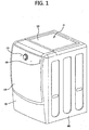
- FIG. 1 illustrates a laundry treatment apparatus according to the present invention.
- the laundry treatment apparatus includes a cabinet 10 defining an external appearance, a drum (not illustrated) rotatably provided inside the cabinet 10 to accommodate laundry therein, a front cover unit 100 provided on the front surface of the cabinet 10, a top cover unit 300 provided on the top surface of the cabinet 10, and a side cover unit 400 provided on the side of the cabinet 10.
- the laundry treatment apparatus may further include a tub (not illustrated), which is provided inside the cabinet 10 and is configured to accommodate wash water therein.
- the front cover unit 100 may further include a door assembly 130 provided to enable the introduction and discharge of laundry.
- the door assembly 130 may include a knob 157, which receives a command to operate the laundry treatment apparatus of the present invention from a user, and an LED unit 159, which displays the operating cycles of the laundry treatment apparatus in response to the operating command input from the user.
- the door assembly 130 includes a hinge unit (140, see FIG. 3 ) provided on one side surface thereof so that the door assembly 130 may be opened or closed about the hinge unit 140 as the rotation axis thereof, and may further include a handle unit (150, see FIG. 3 ) provided on the side surface thereof, which is opposite to the hinge unit 140, in order to assist the user in opening or closing the door 130.
- a hinge unit 140, see FIG. 3
- a handle unit 150, see FIG. 3
- the door assembly 130 has caused inconvenience when the user opens or closes the door assembly 130 because the hinge unit 140 and the handle unit 150 are fixed in position. Therefore, the present invention proposes that positions of the hinge unit 140 and the handle unit 150 provided at the door assembly 130 are exchangeable. A method of exchanging the positions of the hinge unit 140 and the handle unit 150 and configurations thereof will be described later.
- FIG. 2 is a view illustrating a power cable and a connector inside the laundry treatment apparatus according to the present invention.
- FIG. 2(a) illustrates the power cable 200 to supply power to the door assembly 130.
- the power cable 200 serves to receive power from an external source and to supply the power to the door assembly 130.
- the power cable 200 may include a first power cable 210 to supply power to a first female part 213, a second power cable 230 to supply power to a second female part 233, and a branch part 250, at which the power supplied from the external source branches off to the first power cable 210 and to the second power cable 230.
- the first power cable 210 may include a first body 211 and the first female part 213 coupled to a male part 163 provided at the harness connector 160 or the hinge unit 140.
- the second power cable 230 may include a second body 231 and the second female part 233 coupled to the male part 163 provided at the harness connector 160 or the hinge unit 140.
- FIG. 2(b) is a front view illustrating the power cable 200 provided at the cabinet 10.
- a front cover body 110 may include a cover hole 111 to enable the introduction and discharge of laundry, and a cover groove 112 indented to accommodate a gasket, which protrudes from the door assembly 130 and serves to prevent wash water from overflowing out of the cover hole 111.
- the first power cable 210 may be provided at the left lower end of the front cover body 110, and the second power cable 230 may be provided at the right upper end of the front cover body 110.
- positions of the first power cable 210 and the second power cable 230 are not limited to the left lower end and the right upper end, and may be selected from somewhere of the front cover body 110 as needed.
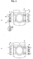
- FIG. 3 is a view illustrating a door of the laundry treatment apparatus according to the present invention.
- FIG. 3(a) illustrates the state before positions of the hinge unit 140 and the handle unit 150 are exchanged
- FIG. 3(b) illustrates the state after positions of the hinge unit 140 and the handle unit 150 are exchanged.
- the door assembly 130 may include a hinge coupling portion 131 coupled to the hinge unit 140, a handle coupling portion 133 coupled to the handle unit 150, and a door connector (not illustrated) provided inside the door assembly 130 to receive power from the power cable 200.
- the door connector may be sufficient so long as it receives power from the power cable 200 and transmits the power to the door assembly 130.
- the handle unit 150 When the user views the door assembly 130 from the front side thereof, the handle unit 150 may be provided at the right side and the hinge unit 140 may be provided at the left side, before positions of the hinge unit 140 and the handle unit 150 are exchanged.
- the hinge unit 140 may include a hinge body 141 having one surface coupled to the door assembly 130 and the other surface provided on the front cover body 110 to enable the pivoting of the door assembly 130, a protrusion 143 protruding from the hinge body 141, a hinge shaft 145 provided on the protrusion 143, and a spring 147 provided on the hinge shaft 145 so as to provide elastic force required to allow the door assembly 130 to return to an original state thereof after the door assembly 130 performs pivoting.
- the spring 147 may be a torsional spring surrounding the outer circumferential surface of the hinge shaft 145.
- both distal ends of the handle unit 150 are designated by A and B, and both distal ends of the hinge unit 140 are designated by C and D.
- the hinge unit 140 and the handle unit 150 are separably coupled to the door assembly 130. Therefore, the hinge unit 140 and the handle unit 150 may be separated from the door assembly 130.
- the handle 150 may come to the left side of the door assembly 130 and the hinge unit 140 may come to the right side of the door assembly 130.
- the handle unit 150 and the hinge unit 140 may come to be inverted up and down.
- the handle unit 150 and the hinge unit 140 may have a point reflection shape about the center of the door assembly 130 as the symmetrical center.
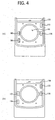
- FIG. 4 is a view illustrating the front cover unit of the laundry treatment apparatus according to the present invention.
- the front cover unit 100 of the laundry treatment apparatus may include the front cover body 110, the cover hole 111 formed in the front cover body 110 to enable the introduction and discharge of laundry, a first hinge coupling portion 113 and a second hinge coupling portion 114, which are provided respectively on different surfaces of the front cover body 110 for the coupling of the first hinge unit 140, and a first latch coupling portion 115 and a second latch coupling portion 116, which are provided respectively on different surfaces of the front cover body 110 for the coupling of a latch mechanism (not illustrated).
- FIG. 4(a) illustrates the front cover body 110 in a case where the hinge unit 140 of the door assembly 130 is coupled at the right side of the front cover body 110 when the user views the front cover body 110 from the front side thereof
- FIG. 4(b) illustrates the front cover body 110 in a case where the hinge unit 140 of the door assembly 130 is coupled to the left side of the front cover body 110 when the user views the front cover body 110 from the front side thereof.
- the structure of the first hinge coupling portion 113, the second hinge coupling portion 114, the first latch coupling portion 115, and the second latch coupling portion 116 of the front cover body 110 must be changed because the positions of the hinge unit 140 and the handle unit 150 of the door assembly 130 are changed.
- the first hinge coupling portion 113 and the second latch coupling portion 116 may be opened because the hinge unit 140 of the door assembly 130 may be provided so as to be connected to the first hinge coupling portion 113 and the second latch coupling portion 116.
- the second hinge coupling portion 114 and the first latch coupling portion 115 which are not coupled to the door assembly 130, may be closed.
- the second hinge coupling portion 114 may be provided with the harness connector (160, see FIG.
- first latch coupling portion 115 may be provided with the latch mechanism , which is separably coupled to the first latch coupling portion 115 and the second latch coupling portion 116.
- the user may remove the harness connector (160, see FIG. 5 ) and the latch mechanism which have closed the second hinge coupling portion 114 and the first latch coupling portion 115.
- the removed harness connector 160 may be coupled to the first hinge coupling portion 113 so as to close the first hinge coupling portion 113, and the removed latch mechanism may be coupled to the second latch coupling portion 116 so as to close the second latch coupling portion 116.
- the latch mechanism and the harness connector 160 may be provided such that coupling positions thereof are changeable in a point reflection manner about the center of the cover hole 111 as the symmetrical center.
- FIG. 5 is a view illustrating the harness connector of the laundry treatment apparatus according to the present invention.
- the harness connector 160 may include a body 161 and the male part 163 protruding from the body 161 so as to be coupled to the door connector (not illustrated).
- the harness connector 160 is provided to close one of the hinge coupling portions 113 and 114 in a case where the hinge unit 140 of the door assembly 130 is not coupled to the hinge coupling portion 113 or 114 of the front cover body 110, and thus may function as a so-called dummy connector.
- the user may protect the door connector (not illustrated) from external shocks.
- the male part 163 and the door connector may be provided to implement connector coupling that is generally used in the art of the present invention. A detailed description related to the connector coupling is omitted herein.
- FIG. 5 illustrates that the harness connector 160 has the male part 163 and the door connector (not illustrated) has the female part
- the harness connector 160 may have the female part
- the door connector (not illustrated) may have the male part
- FIG. 6 is a view illustrating the coupling relationship between the door and the front cover unit of the laundry treatment apparatus according to the present invention.
- the following description is based on the state in which the door assembly 130 is mounted at the right side of the front cover body 110 when the user views the front cover body 110 from the front side thereof.
- the door assembly 130 may be disassembled from the front cover body 110. As described above with reference to FIG. 3 , the user may change the position of the hinge unit 140 of the door assembly 130 by exchanging the positions of the hinge unit 140 and the handle unit 150 of the door assembly 130.
- the user disassembles the harness connector 160 and the latch mechanism , which are separably coupled to the first latch coupling portion 115 and the second hinge coupling portion 114 of the front cover body 110, and thereafter couples the harness connector 160 and the latch mechanism to the second latch coupling portion 116 and the first hinge coupling portion 113.
- the hinge unit 140 of the door assembly 110 is located at the left side when the user views the front cover body 110 from the front side thereof. Thus, the hinge unit 140 may be coupled to the first latch coupling portion 115 and the second hinge coupling portion 114 of the front cover body 110.
- the hinge unit 140 may implement connector coupling with the first female part 213 provided in the first power cable 210.
- a separate cap may be provided.
- the configuration in which the hinge unit 140 is mounted at the right side of the front cover body 110 such that the user opens or closes the door assembly 130 with their left hand may be changed to the configuration in which the hinge unit 140 is mounted at the left side of the front cover body 110 such that the user opens or closes the door assembly 130 with their right hand.
- the present invention may provide a laundry treatment apparatus and a door thereof, in which positions of a hinge assembly and a handle assembly provided at the door are exchangeable, in order to ensure that the user conveniently opens or closes the door.
- the present invention may provide a laundry treatment apparatus and a door thereof, which allows a user to more conveniently exchange positions of a hinge assembly and a handle assembly provided at the door.
Landscapes
- Engineering & Computer Science (AREA)
- Textile Engineering (AREA)
- Mechanical Engineering (AREA)
- General Engineering & Computer Science (AREA)
- Life Sciences & Earth Sciences (AREA)
- Sustainable Development (AREA)
- Main Body Construction Of Washing Machines And Laundry Dryers (AREA)
- Detail Structures Of Washing Machines And Dryers (AREA)
Claims (7)
- Wäschebehandlungsvorrichtung, die aufweist:einen Kasten (10), der einen Aufnahmeraum bereitstellt;eine Trommel, die drehbar im Inneren des Kastens (10) bereitgestellt ist;eine vordere Abdeckeinheit (100), die auf einem Abschnitt einer vorderen Oberfläche des Kastens (10) bereitgestellt ist und ein Abdeckungsloch (111) hat, das bereitgestellt ist, um das Einführen und Entnehmen eines Wäscheobjekts in die Trommel zu ermöglichen; undeine Klappenanordnung (130), die auf der vorderen Abdeckeinheit (100) bereitgestellt ist, um das Abdeckungsloch (111) zu öffnen oder zu schließen,wobei die Klappenanordnung (130) umfasst:eine Gelenkeinheit (140), die eine Seite trennbar mit der vorderen Abdeckeinheit (100) gekoppelt hat und eine verbleibende Seite trennbar mit der Klappenanordnung (130) gekoppelt hat, um eine Drehung der Klappenanordnung (130) zuzulassen; undeine Griffeinheit (150), die trennbar mit der Klappenanordnung (130) gekoppelt ist, wobei die Griffeinheit (150) geeignet ist, zuzulassen, dass die Klappenanordnung (130) von der vorderen Abdeckeinheit (100) trennbar ist, undwobei die Gelenkeinheit (140) und die Griffeinheit (150) trennbar mit der Klappenanordnung (130) gekoppelt sind und geeignet sind, einen Wechsel ihrer Positionen zuzulassen,wobei die Vorrichtung dadurch gekennzeichnet ist, dass sie ferner ein Stromkabel (200) aufweist, das aufgebaut ist, um Leistung von einer externen Quelle zu empfangen,wobei das Stromkabel (200) umfasst:ein erstes Stromkabel (210), das bereitgestellt ist, um mit einer Seite der vorderen Abdeckeinheit (100) verbunden zu werden;ein zweites Stromkabel (230), das bereitgestellt ist, um mit einer verbleibenden Seite der vorderen Abdeckeinheit verbunden zu werden; undeinen Verzweigungsteil (250), an dem die Leistung, die von der externen Quelle an das Stromkabel (200) geliefert wird, zu dem ersten Stromkabel (210) und dem zweiten Stromkabel (230) verzweigt, wobei die Klappenanordnung (130) ferner einen Klappenstecker, der mit dem wenigstens einen des ersten Stromkabels (210) oder des zweiten Stromkabels (230) verbunden ist, um die von der externen Quelle empfangene Leistung an die Klappenanordnung (130) zu übertragen.
- Wäschebehandlungsvorrichtung nach Anspruch 1, wobei die Gelenkeinheit (140) und die Griffeinheit (150) eine Punktspiegelform um die Mitte der Klappenanordnung (130) als das Symmetriezentrum haben.
- Wäschebehandlungsvorrichtung nach Anspruch 2, die ferner einen Kabelbaumstecker (160) aufweist, der mit dem wenigstens einen des ersten Stromkabels (210) oder des zweiten Stromkabels (230) verbunden ist, das nicht mit dem Klappenstecker verbunden ist.
- Wäschebehandlungsvorrichtung nach einem der Ansprüche 1 bis 3, die ferner einen Verriegelungsmechanismus aufweist, der auf der vorderen Abdeckeinheit (100) bereitgestellt ist, um die Griffeinheit (150) zu beschränken.
- Wäschebehandlungsvorrichtung nach Anspruch 4, wobei der Verriegelungsmechanismus trennbar auf der vorderen Abdeckeinheit (100) bereitgestellt ist, so dass er an einer Position angeordnet ist, die der Griffeinheit (150) entspricht.
- Wäschebehandlungsvorrichtung nach Anspruch 4 oder 5, die ferner aufweist: einen ersten Gelenkkopplungsabschnitt (113) und einen zweiten Gelenkkopplungsabschnitt (114), die jeweils auf verschiedenen Oberflächen des vorderen Abdeckkörpers (110) für die Kopplung der Gelenkeinheit (140) bereitgestellt sind, und einen ersten Riegelkopplungsabschnitt (115) und einen zweiten Riegelkopplungsabschnitt (116), die jeweils auf verschiedenen Oberflächen des vorderen Abdeckkörpers (110) für die Kopplung eines Verriegelungsmechanismus bereitgestellt sind.
- Wäschebehandlungsvorrichtung nach Anspruch 4, 5 oder 6, wobei der Verriegelungsmechanismus und der Kabelbaumstecker (160) derart bereitgestellt sind, dass ihre Kopplungspositionen in einer Punktspiegelweise um die Mitte des Abdecklochs (111) als das Symmetriezentrum austauschbar sind.
Applications Claiming Priority (1)
| Application Number | Priority Date | Filing Date | Title |
|---|---|---|---|
| KR1020150000734A KR102309292B1 (ko) | 2015-01-05 | 2015-01-05 | 의류처리장치 및 그 도어 |
Publications (2)
| Publication Number | Publication Date |
|---|---|
| EP3040468A1 EP3040468A1 (de) | 2016-07-06 |
| EP3040468B1 true EP3040468B1 (de) | 2017-06-21 |
Family
ID=55070855
Family Applications (1)
| Application Number | Title | Priority Date | Filing Date |
|---|---|---|---|
| EP16150228.1A Active EP3040468B1 (de) | 2015-01-05 | 2016-01-05 | Wäschebehandlungsvorrichtung und tür dafür |
Country Status (4)
| Country | Link |
|---|---|
| US (1) | US10053810B2 (de) |
| EP (1) | EP3040468B1 (de) |
| KR (1) | KR102309292B1 (de) |
| CN (2) | CN105862354B (de) |
Families Citing this family (13)
| Publication number | Priority date | Publication date | Assignee | Title |
|---|---|---|---|---|
| KR102202721B1 (ko) | 2015-02-25 | 2021-01-13 | 삼성전자주식회사 | 세탁기 |
| KR102594899B1 (ko) | 2016-09-23 | 2023-10-27 | 엘지전자 주식회사 | 의류처리장치 |
| KR102585492B1 (ko) | 2016-09-23 | 2023-10-06 | 엘지전자 주식회사 | 의류처리장치 |
| KR102594898B1 (ko) | 2016-09-23 | 2023-10-27 | 엘지전자 주식회사 | 의류처리장치 |
| KR102585491B1 (ko) | 2016-09-23 | 2023-10-06 | 엘지전자 주식회사 | 의류처리장치 |
| US10294712B2 (en) * | 2016-11-14 | 2019-05-21 | Whirlpool Corporation | Appliance door assembly |
| PL3323929T3 (pl) | 2016-11-21 | 2021-06-28 | Electrolux Appliances Aktiebolag | Zespół drzwi do maszyny do obróbki prania |
| KR102368505B1 (ko) * | 2017-06-14 | 2022-02-28 | 주식회사 위니아전자 | 벽걸이형 세탁기 |
| CN109487481B (zh) * | 2017-09-13 | 2021-07-16 | 青岛胶州海尔洗涤电器有限公司 | 一种衣物处理设备 |
| CN109898296B (zh) * | 2017-12-07 | 2021-08-27 | 青岛海尔洗涤电器有限公司 | 一种洗衣机门及洗衣机 |
| CN112144249B (zh) * | 2019-06-27 | 2023-11-17 | 博西华电器(江苏)有限公司 | 洗衣设备 |
| CN114000324B (zh) * | 2021-11-30 | 2025-09-19 | 无锡小天鹅电器有限公司 | 铰链组件和衣物处理装置 |
| DE102023203067A1 (de) * | 2023-04-03 | 2024-10-10 | BSH Hausgeräte GmbH | Wäschepflegegerät zum Pflegen von Gegenständen |
Family Cites Families (34)
| Publication number | Priority date | Publication date | Assignee | Title |
|---|---|---|---|---|
| US4340991A (en) * | 1979-07-17 | 1982-07-27 | Gidseg Edward D | Demountable hinge |
| GB2081858B (en) * | 1980-08-08 | 1984-01-18 | Philips Electronic Associated | Domestic appliance |
| JP2784369B2 (ja) * | 1993-08-30 | 1998-08-06 | 矢崎総業株式会社 | パネルロックコネクタ |
| KR19980086233A (ko) * | 1997-05-31 | 1998-12-05 | 윤종용 | 냉장고용 도어의 케이블 인출 구조 |
| US5941619A (en) * | 1997-09-24 | 1999-08-24 | White Consolidated Industries, Inc. | Electrical connector for a refrigerator and method of installing |
| KR20000073299A (ko) | 1999-05-10 | 2000-12-05 | 구자홍 | 전자동세탁기의 도어스위치 구조 |
| KR100479075B1 (ko) | 2002-07-11 | 2005-03-28 | 엘지전자 주식회사 | 건조기 |
| WO2005042891A1 (en) * | 2003-10-31 | 2005-05-12 | Arcelik Anonim Sirketi | Domestic appliance with two directional hinge |
| KR101133608B1 (ko) * | 2004-04-23 | 2012-04-10 | 엘지전자 주식회사 | 세탁기의 도어스위치와 커넥터 연결구조 |
| KR20050102915A (ko) | 2004-04-23 | 2005-10-27 | 엘지전자 주식회사 | 세탁기의 통풍장치 |
| KR100719846B1 (ko) * | 2004-10-22 | 2007-05-18 | 엘지전자 주식회사 | 세탁물 처리장치 |
| US7601913B2 (en) * | 2005-04-04 | 2009-10-13 | Samsung Gwangju Electronics Co., Ltd. | Wire harness fixing device |
| US7494418B2 (en) * | 2005-05-27 | 2009-02-24 | Wms Gaming Inc. | Gaming machine with hinged top box |
| KR20070065139A (ko) * | 2005-12-19 | 2007-06-22 | 주식회사 대우일렉트로닉스 | 드럼세탁기의 도어개폐방향 변경구조 |
| KR101552353B1 (ko) * | 2006-10-18 | 2015-09-10 | 타이코에이엠피 주식회사 | 차량 도어용 케이블 연결 커넥터 |
| US8299656B2 (en) * | 2008-03-12 | 2012-10-30 | Whirlpool Corporation | Feature module connection system |
| US7651368B2 (en) * | 2007-01-04 | 2010-01-26 | Whirpool Corporation | Appliance with an adapter to simultaneously couple multiple consumer electronic devices |
| US7980088B2 (en) * | 2007-01-04 | 2011-07-19 | Whirlpool Corporation | Removable adapter providing a wireless service to removable consumer electronic device |
| KR101424554B1 (ko) * | 2007-01-23 | 2014-07-31 | 삼성전자 주식회사 | 양방향 개폐 가능한 도어유닛 및 이를 포함하는 냉장고 |
| US7614116B2 (en) * | 2007-05-04 | 2009-11-10 | King Slide Works Co., Ltd. | Multi-directional adjustment hinge |
| US20080271291A1 (en) * | 2007-05-04 | 2008-11-06 | Ken-Ching Chen | Multi-directional adjustment hinge |
| DE102009019224B4 (de) * | 2008-04-30 | 2016-06-09 | Lg Electronics Inc. | Maschine zum Behandeln von Textil- und Lederwaren |
| KR101643633B1 (ko) | 2009-07-30 | 2016-08-10 | 엘지전자 주식회사 | 세탁장치 |
| EP2607546A4 (de) * | 2010-08-19 | 2016-03-23 | Lg Electronics Inc | Waschmaschine mit einer trocknungsfunktion und verfahren zu ihrer steuerung |
| US9455561B2 (en) * | 2010-10-01 | 2016-09-27 | Modernfold, Inc. | Movable wall panel system with electrical connections |
| US8936330B2 (en) * | 2010-12-23 | 2015-01-20 | Lg Electronics Inc. | Laundry treating apparatus |
| US8820861B2 (en) * | 2010-12-23 | 2014-09-02 | Lg Electronics Inc. | Laundry treating apparatus |
| US20120242207A1 (en) * | 2011-03-22 | 2012-09-27 | Martin Mershon | Connection point for communication device on appliance |
| CN102840220A (zh) * | 2011-06-21 | 2012-12-26 | 鸿富锦精密工业(深圳)有限公司 | 铰链结构 |
| WO2013087774A1 (en) * | 2011-12-16 | 2013-06-20 | BSH Bosch und Siemens Hausgeräte GmbH | Household appliance including a power supply module and a power consumption module |
| CN103166326A (zh) * | 2011-12-16 | 2013-06-19 | 博西华电器(江苏)有限公司 | 家用电器 |
| US9212843B2 (en) * | 2012-12-03 | 2015-12-15 | Whirlpool Corporation | Custom bin interface |
| EP2808434B1 (de) * | 2013-05-30 | 2016-05-11 | Electrolux Appliances Aktiebolag | Wäschebehandlungsvorrichtung mit Türanordnung |
| KR101944361B1 (ko) * | 2014-01-06 | 2019-02-01 | 삼성전자주식회사 | 커넥터 및 이를 포함하는 냉장고 |
-
2015
- 2015-01-05 KR KR1020150000734A patent/KR102309292B1/ko active Active
-
2016
- 2016-01-05 US US14/988,164 patent/US10053810B2/en active Active
- 2016-01-05 EP EP16150228.1A patent/EP3040468B1/de active Active
- 2016-01-05 CN CN201610282472.XA patent/CN105862354B/zh active Active
- 2016-01-05 CN CN201610006151.7A patent/CN105755760B/zh active Active
Non-Patent Citations (1)
| Title |
|---|
| None * |
Also Published As
| Publication number | Publication date |
|---|---|
| CN105862354B (zh) | 2018-10-26 |
| CN105755760B (zh) | 2018-01-30 |
| US20160194802A1 (en) | 2016-07-07 |
| CN105755760A (zh) | 2016-07-13 |
| US10053810B2 (en) | 2018-08-21 |
| KR102309292B1 (ko) | 2021-10-06 |
| CN105862354A (zh) | 2016-08-17 |
| EP3040468A1 (de) | 2016-07-06 |
| KR20160084167A (ko) | 2016-07-13 |
Similar Documents
| Publication | Publication Date | Title |
|---|---|---|
| EP3040468B1 (de) | Wäschebehandlungsvorrichtung und tür dafür | |
| US9650737B2 (en) | Laundry treating apparatus | |
| EP3040467B1 (de) | Wäschebehandlungsvorrichtung | |
| EP3189179B1 (de) | Waschmaschine | |
| US20160076186A1 (en) | Laundry treating apparatus | |
| CN101812795B (zh) | 具备有门组件的衣物处理装置 | |
| EP2478144B1 (de) | Trommelwaschmaschine | |
| US20130232810A1 (en) | Door handle for a washing machine or dryer appliance | |
| RU2329341C2 (ru) | Стиральная/сушильная машина | |
| CN103306107A (zh) | 洗衣机的洗涤剂盒 | |
| CN105671869A (zh) | 洗衣机 | |
| KR20160084327A (ko) | 의류처리장치 및 그 도어 | |
| US11946302B2 (en) | Home appliance | |
| KR20180079882A (ko) | 도어 유닛 및 이를 구비하는 의류처리장치 | |
| KR20150109817A (ko) | 의류처리장치 | |
| KR20170082110A (ko) | 의류처리장치 | |
| CN109338679A (zh) | 方便投放衣物的滚筒洗衣机 | |
| KR101706969B1 (ko) | 의류처리장치 및 도어 | |
| ES2649723T3 (es) | Una puerta para cerrar una abertura de una carcasa de un aparato electrodoméstico para el tratamiento de colada de ropa, un aparato electrodoméstico para el tratamiento de colada de ropa y un método para fabricar una puerta respectiva | |
| JP5707523B2 (ja) | 電気洗濯機 | |
| KR101706968B1 (ko) | 의류처리장치 및 도어 | |
| SI23836A (sl) | Ročaj vrat gospodinjskega aparata | |
| KR20160084074A (ko) | 의류처리장치 | |
| KR102150443B1 (ko) | 세탁물 처리장치 | |
| KR20160084326A (ko) | 의류처리장치 및 도어 |
Legal Events
| Date | Code | Title | Description |
|---|---|---|---|
| PUAI | Public reference made under article 153(3) epc to a published international application that has entered the european phase |
Free format text: ORIGINAL CODE: 0009012 |
|
| 17P | Request for examination filed |
Effective date: 20160205 |
|
| AK | Designated contracting states |
Kind code of ref document: A1 Designated state(s): AL AT BE BG CH CY CZ DE DK EE ES FI FR GB GR HR HU IE IS IT LI LT LU LV MC MK MT NL NO PL PT RO RS SE SI SK SM TR |
|
| AX | Request for extension of the european patent |
Extension state: BA ME |
|
| RBV | Designated contracting states (corrected) |
Designated state(s): AL AT BE BG CH CY CZ DE DK EE ES FI FR GB GR HR HU IE IS IT LI LT LU LV MC MK MT NL NO PL PT RO RS SE SI SK SM TR |
|
| REG | Reference to a national code |
Ref country code: DE Ref legal event code: R079 Ref document number: 602016000088 Country of ref document: DE Free format text: PREVIOUS MAIN CLASS: D06F0039140000 Ipc: F26B0025140000 |
|
| RIC1 | Information provided on ipc code assigned before grant |
Ipc: F26B 23/04 20060101ALI20161212BHEP Ipc: F26B 25/14 20060101AFI20161212BHEP Ipc: F26B 11/04 20060101ALI20161212BHEP Ipc: F26B 25/08 20060101ALI20161212BHEP Ipc: D06F 39/12 20060101ALN20161212BHEP Ipc: D06F 39/14 20060101ALI20161212BHEP |
|
| GRAP | Despatch of communication of intention to grant a patent |
Free format text: ORIGINAL CODE: EPIDOSNIGR1 |
|
| INTG | Intention to grant announced |
Effective date: 20170127 |
|
| RIC1 | Information provided on ipc code assigned before grant |
Ipc: D06F 39/12 20060101ALN20170116BHEP Ipc: F26B 25/14 20060101AFI20170116BHEP Ipc: D06F 39/14 20060101ALI20170116BHEP Ipc: F26B 23/04 20060101ALI20170116BHEP Ipc: F26B 25/08 20060101ALI20170116BHEP Ipc: F26B 11/04 20060101ALI20170116BHEP |
|
| GRAS | Grant fee paid |
Free format text: ORIGINAL CODE: EPIDOSNIGR3 |
|
| GRAA | (expected) grant |
Free format text: ORIGINAL CODE: 0009210 |
|
| AK | Designated contracting states |
Kind code of ref document: B1 Designated state(s): AL AT BE BG CH CY CZ DE DK EE ES FI FR GB GR HR HU IE IS IT LI LT LU LV MC MK MT NL NO PL PT RO RS SE SI SK SM TR |
|
| REG | Reference to a national code |
Ref country code: GB Ref legal event code: FG4D |
|
| REG | Reference to a national code |
Ref country code: CH Ref legal event code: EP |
|
| REG | Reference to a national code |
Ref country code: IE Ref legal event code: FG4D |
|
| REG | Reference to a national code |
Ref country code: AT Ref legal event code: REF Ref document number: 903344 Country of ref document: AT Kind code of ref document: T Effective date: 20170715 |
|
| REG | Reference to a national code |
Ref country code: DE Ref legal event code: R096 Ref document number: 602016000088 Country of ref document: DE |
|
| REG | Reference to a national code |
Ref country code: NL Ref legal event code: MP Effective date: 20170621 |
|
| PG25 | Lapsed in a contracting state [announced via postgrant information from national office to epo] |
Ref country code: FI Free format text: LAPSE BECAUSE OF FAILURE TO SUBMIT A TRANSLATION OF THE DESCRIPTION OR TO PAY THE FEE WITHIN THE PRESCRIBED TIME-LIMIT Effective date: 20170621 Ref country code: NO Free format text: LAPSE BECAUSE OF FAILURE TO SUBMIT A TRANSLATION OF THE DESCRIPTION OR TO PAY THE FEE WITHIN THE PRESCRIBED TIME-LIMIT Effective date: 20170921 Ref country code: HR Free format text: LAPSE BECAUSE OF FAILURE TO SUBMIT A TRANSLATION OF THE DESCRIPTION OR TO PAY THE FEE WITHIN THE PRESCRIBED TIME-LIMIT Effective date: 20170621 Ref country code: GR Free format text: LAPSE BECAUSE OF FAILURE TO SUBMIT A TRANSLATION OF THE DESCRIPTION OR TO PAY THE FEE WITHIN THE PRESCRIBED TIME-LIMIT Effective date: 20170922 Ref country code: LT Free format text: LAPSE BECAUSE OF FAILURE TO SUBMIT A TRANSLATION OF THE DESCRIPTION OR TO PAY THE FEE WITHIN THE PRESCRIBED TIME-LIMIT Effective date: 20170621 |
|
| REG | Reference to a national code |
Ref country code: LT Ref legal event code: MG4D |
|
| REG | Reference to a national code |
Ref country code: AT Ref legal event code: MK05 Ref document number: 903344 Country of ref document: AT Kind code of ref document: T Effective date: 20170621 |
|
| PG25 | Lapsed in a contracting state [announced via postgrant information from national office to epo] |
Ref country code: SE Free format text: LAPSE BECAUSE OF FAILURE TO SUBMIT A TRANSLATION OF THE DESCRIPTION OR TO PAY THE FEE WITHIN THE PRESCRIBED TIME-LIMIT Effective date: 20170621 Ref country code: NL Free format text: LAPSE BECAUSE OF FAILURE TO SUBMIT A TRANSLATION OF THE DESCRIPTION OR TO PAY THE FEE WITHIN THE PRESCRIBED TIME-LIMIT Effective date: 20170621 Ref country code: RS Free format text: LAPSE BECAUSE OF FAILURE TO SUBMIT A TRANSLATION OF THE DESCRIPTION OR TO PAY THE FEE WITHIN THE PRESCRIBED TIME-LIMIT Effective date: 20170621 Ref country code: LV Free format text: LAPSE BECAUSE OF FAILURE TO SUBMIT A TRANSLATION OF THE DESCRIPTION OR TO PAY THE FEE WITHIN THE PRESCRIBED TIME-LIMIT Effective date: 20170621 Ref country code: BG Free format text: LAPSE BECAUSE OF FAILURE TO SUBMIT A TRANSLATION OF THE DESCRIPTION OR TO PAY THE FEE WITHIN THE PRESCRIBED TIME-LIMIT Effective date: 20170921 |
|
| REG | Reference to a national code |
Ref country code: FR Ref legal event code: PLFP Year of fee payment: 3 |
|
| PG25 | Lapsed in a contracting state [announced via postgrant information from national office to epo] |
Ref country code: CZ Free format text: LAPSE BECAUSE OF FAILURE TO SUBMIT A TRANSLATION OF THE DESCRIPTION OR TO PAY THE FEE WITHIN THE PRESCRIBED TIME-LIMIT Effective date: 20170621 Ref country code: EE Free format text: LAPSE BECAUSE OF FAILURE TO SUBMIT A TRANSLATION OF THE DESCRIPTION OR TO PAY THE FEE WITHIN THE PRESCRIBED TIME-LIMIT Effective date: 20170621 Ref country code: RO Free format text: LAPSE BECAUSE OF FAILURE TO SUBMIT A TRANSLATION OF THE DESCRIPTION OR TO PAY THE FEE WITHIN THE PRESCRIBED TIME-LIMIT Effective date: 20170621 Ref country code: SK Free format text: LAPSE BECAUSE OF FAILURE TO SUBMIT A TRANSLATION OF THE DESCRIPTION OR TO PAY THE FEE WITHIN THE PRESCRIBED TIME-LIMIT Effective date: 20170621 Ref country code: AT Free format text: LAPSE BECAUSE OF FAILURE TO SUBMIT A TRANSLATION OF THE DESCRIPTION OR TO PAY THE FEE WITHIN THE PRESCRIBED TIME-LIMIT Effective date: 20170621 |
|
| PG25 | Lapsed in a contracting state [announced via postgrant information from national office to epo] |
Ref country code: PL Free format text: LAPSE BECAUSE OF FAILURE TO SUBMIT A TRANSLATION OF THE DESCRIPTION OR TO PAY THE FEE WITHIN THE PRESCRIBED TIME-LIMIT Effective date: 20170621 Ref country code: SM Free format text: LAPSE BECAUSE OF FAILURE TO SUBMIT A TRANSLATION OF THE DESCRIPTION OR TO PAY THE FEE WITHIN THE PRESCRIBED TIME-LIMIT Effective date: 20170621 Ref country code: IS Free format text: LAPSE BECAUSE OF FAILURE TO SUBMIT A TRANSLATION OF THE DESCRIPTION OR TO PAY THE FEE WITHIN THE PRESCRIBED TIME-LIMIT Effective date: 20171021 Ref country code: IT Free format text: LAPSE BECAUSE OF FAILURE TO SUBMIT A TRANSLATION OF THE DESCRIPTION OR TO PAY THE FEE WITHIN THE PRESCRIBED TIME-LIMIT Effective date: 20170621 Ref country code: ES Free format text: LAPSE BECAUSE OF FAILURE TO SUBMIT A TRANSLATION OF THE DESCRIPTION OR TO PAY THE FEE WITHIN THE PRESCRIBED TIME-LIMIT Effective date: 20170621 |
|
| REG | Reference to a national code |
Ref country code: DE Ref legal event code: R097 Ref document number: 602016000088 Country of ref document: DE |
|
| PLBE | No opposition filed within time limit |
Free format text: ORIGINAL CODE: 0009261 |
|
| STAA | Information on the status of an ep patent application or granted ep patent |
Free format text: STATUS: NO OPPOSITION FILED WITHIN TIME LIMIT |
|
| PG25 | Lapsed in a contracting state [announced via postgrant information from national office to epo] |
Ref country code: DK Free format text: LAPSE BECAUSE OF FAILURE TO SUBMIT A TRANSLATION OF THE DESCRIPTION OR TO PAY THE FEE WITHIN THE PRESCRIBED TIME-LIMIT Effective date: 20170621 |
|
| 26N | No opposition filed |
Effective date: 20180322 |
|
| PG25 | Lapsed in a contracting state [announced via postgrant information from national office to epo] |
Ref country code: SI Free format text: LAPSE BECAUSE OF FAILURE TO SUBMIT A TRANSLATION OF THE DESCRIPTION OR TO PAY THE FEE WITHIN THE PRESCRIBED TIME-LIMIT Effective date: 20170621 |
|
| PG25 | Lapsed in a contracting state [announced via postgrant information from national office to epo] |
Ref country code: LU Free format text: LAPSE BECAUSE OF NON-PAYMENT OF DUE FEES Effective date: 20180105 |
|
| REG | Reference to a national code |
Ref country code: IE Ref legal event code: MM4A |
|
| REG | Reference to a national code |
Ref country code: BE Ref legal event code: MM Effective date: 20180131 |
|
| PG25 | Lapsed in a contracting state [announced via postgrant information from national office to epo] |
Ref country code: BE Free format text: LAPSE BECAUSE OF NON-PAYMENT OF DUE FEES Effective date: 20180131 |
|
| PG25 | Lapsed in a contracting state [announced via postgrant information from national office to epo] |
Ref country code: IE Free format text: LAPSE BECAUSE OF NON-PAYMENT OF DUE FEES Effective date: 20180105 |
|
| PG25 | Lapsed in a contracting state [announced via postgrant information from national office to epo] |
Ref country code: MC Free format text: LAPSE BECAUSE OF FAILURE TO SUBMIT A TRANSLATION OF THE DESCRIPTION OR TO PAY THE FEE WITHIN THE PRESCRIBED TIME-LIMIT Effective date: 20170621 |
|
| REG | Reference to a national code |
Ref country code: CH Ref legal event code: PL |
|
| PG25 | Lapsed in a contracting state [announced via postgrant information from national office to epo] |
Ref country code: LI Free format text: LAPSE BECAUSE OF NON-PAYMENT OF DUE FEES Effective date: 20190131 Ref country code: CH Free format text: LAPSE BECAUSE OF NON-PAYMENT OF DUE FEES Effective date: 20190131 |
|
| PG25 | Lapsed in a contracting state [announced via postgrant information from national office to epo] |
Ref country code: MT Free format text: LAPSE BECAUSE OF NON-PAYMENT OF DUE FEES Effective date: 20180105 |
|
| PG25 | Lapsed in a contracting state [announced via postgrant information from national office to epo] |
Ref country code: TR Free format text: LAPSE BECAUSE OF FAILURE TO SUBMIT A TRANSLATION OF THE DESCRIPTION OR TO PAY THE FEE WITHIN THE PRESCRIBED TIME-LIMIT Effective date: 20170621 |
|
| PG25 | Lapsed in a contracting state [announced via postgrant information from national office to epo] |
Ref country code: PT Free format text: LAPSE BECAUSE OF FAILURE TO SUBMIT A TRANSLATION OF THE DESCRIPTION OR TO PAY THE FEE WITHIN THE PRESCRIBED TIME-LIMIT Effective date: 20170621 |
|
| PG25 | Lapsed in a contracting state [announced via postgrant information from national office to epo] |
Ref country code: MK Free format text: LAPSE BECAUSE OF NON-PAYMENT OF DUE FEES Effective date: 20170621 Ref country code: CY Free format text: LAPSE BECAUSE OF FAILURE TO SUBMIT A TRANSLATION OF THE DESCRIPTION OR TO PAY THE FEE WITHIN THE PRESCRIBED TIME-LIMIT Effective date: 20170621 Ref country code: HU Free format text: LAPSE BECAUSE OF FAILURE TO SUBMIT A TRANSLATION OF THE DESCRIPTION OR TO PAY THE FEE WITHIN THE PRESCRIBED TIME-LIMIT; INVALID AB INITIO Effective date: 20160105 |
|
| PG25 | Lapsed in a contracting state [announced via postgrant information from national office to epo] |
Ref country code: AL Free format text: LAPSE BECAUSE OF FAILURE TO SUBMIT A TRANSLATION OF THE DESCRIPTION OR TO PAY THE FEE WITHIN THE PRESCRIBED TIME-LIMIT Effective date: 20170621 |
|
| PGFP | Annual fee paid to national office [announced via postgrant information from national office to epo] |
Ref country code: GB Payment date: 20231207 Year of fee payment: 9 |
|
| GBPC | Gb: european patent ceased through non-payment of renewal fee |
Effective date: 20250105 |
|
| PG25 | Lapsed in a contracting state [announced via postgrant information from national office to epo] |
Ref country code: GB Free format text: LAPSE BECAUSE OF NON-PAYMENT OF DUE FEES Effective date: 20250105 |
|
| PGFP | Annual fee paid to national office [announced via postgrant information from national office to epo] |
Ref country code: FR Payment date: 20251209 Year of fee payment: 11 |
|
| PGFP | Annual fee paid to national office [announced via postgrant information from national office to epo] |
Ref country code: DE Payment date: 20251208 Year of fee payment: 11 |