EP3040384B1 - Rotorkonstruktion für hochgeschwindigkeitsmotoren und herstellungsmethode - Google Patents
Rotorkonstruktion für hochgeschwindigkeitsmotoren und herstellungsmethode Download PDFInfo
- Publication number
- EP3040384B1 EP3040384B1 EP15003688.7A EP15003688A EP3040384B1 EP 3040384 B1 EP3040384 B1 EP 3040384B1 EP 15003688 A EP15003688 A EP 15003688A EP 3040384 B1 EP3040384 B1 EP 3040384B1
- Authority
- EP
- European Patent Office
- Prior art keywords
- coating
- rotor
- shaft
- alloy material
- rotor shaft
- Prior art date
- Legal status (The legal status is an assumption and is not a legal conclusion. Google has not performed a legal analysis and makes no representation as to the accuracy of the status listed.)
- Revoked
Links
Images
Classifications
-
- C—CHEMISTRY; METALLURGY
- C23—COATING METALLIC MATERIAL; COATING MATERIAL WITH METALLIC MATERIAL; CHEMICAL SURFACE TREATMENT; DIFFUSION TREATMENT OF METALLIC MATERIAL; COATING BY VACUUM EVAPORATION, BY SPUTTERING, BY ION IMPLANTATION OR BY CHEMICAL VAPOUR DEPOSITION, IN GENERAL; INHIBITING CORROSION OF METALLIC MATERIAL OR INCRUSTATION IN GENERAL
- C23C—COATING METALLIC MATERIAL; COATING MATERIAL WITH METALLIC MATERIAL; SURFACE TREATMENT OF METALLIC MATERIAL BY DIFFUSION INTO THE SURFACE, BY CHEMICAL CONVERSION OR SUBSTITUTION; COATING BY VACUUM EVAPORATION, BY SPUTTERING, BY ION IMPLANTATION OR BY CHEMICAL VAPOUR DEPOSITION, IN GENERAL
- C23C30/00—Coating with metallic material characterised only by the composition of the metallic material, i.e. not characterised by the coating process
-
- F—MECHANICAL ENGINEERING; LIGHTING; HEATING; WEAPONS; BLASTING
- F04—POSITIVE - DISPLACEMENT MACHINES FOR LIQUIDS; PUMPS FOR LIQUIDS OR ELASTIC FLUIDS
- F04D—NON-POSITIVE-DISPLACEMENT PUMPS
- F04D29/00—Details, component parts, or accessories
- F04D29/02—Selection of particular materials
-
- C—CHEMISTRY; METALLURGY
- C09—DYES; PAINTS; POLISHES; NATURAL RESINS; ADHESIVES; COMPOSITIONS NOT OTHERWISE PROVIDED FOR; APPLICATIONS OF MATERIALS NOT OTHERWISE PROVIDED FOR
- C09D—COATING COMPOSITIONS, e.g. PAINTS, VARNISHES OR LACQUERS; FILLING PASTES; CHEMICAL PAINT OR INK REMOVERS; INKS; CORRECTING FLUIDS; WOODSTAINS; PASTES OR SOLIDS FOR COLOURING OR PRINTING; USE OF MATERIALS THEREFOR
- C09D5/00—Coating compositions, e.g. paints, varnishes or lacquers, characterised by their physical nature or the effects produced; Filling pastes
- C09D5/24—Electrically-conducting paints
-
- F—MECHANICAL ENGINEERING; LIGHTING; HEATING; WEAPONS; BLASTING
- F01—MACHINES OR ENGINES IN GENERAL; ENGINE PLANTS IN GENERAL; STEAM ENGINES
- F01D—NON-POSITIVE DISPLACEMENT MACHINES OR ENGINES, e.g. STEAM TURBINES
- F01D25/00—Component parts, details, or accessories, not provided for in, or of interest apart from, other groups
- F01D25/005—Selecting particular materials
-
- F—MECHANICAL ENGINEERING; LIGHTING; HEATING; WEAPONS; BLASTING
- F01—MACHINES OR ENGINES IN GENERAL; ENGINE PLANTS IN GENERAL; STEAM ENGINES
- F01D—NON-POSITIVE DISPLACEMENT MACHINES OR ENGINES, e.g. STEAM TURBINES
- F01D5/00—Blades; Blade-carrying members; Heating, heat-insulating, cooling or antivibration means on the blades or the members
- F01D5/02—Blade-carrying members, e.g. rotors
-
- F—MECHANICAL ENGINEERING; LIGHTING; HEATING; WEAPONS; BLASTING
- F04—POSITIVE - DISPLACEMENT MACHINES FOR LIQUIDS; PUMPS FOR LIQUIDS OR ELASTIC FLUIDS
- F04D—NON-POSITIVE-DISPLACEMENT PUMPS
- F04D29/00—Details, component parts, or accessories
- F04D29/04—Shafts or bearings, or assemblies thereof
- F04D29/043—Shafts
-
- H—ELECTRICITY
- H02—GENERATION; CONVERSION OR DISTRIBUTION OF ELECTRIC POWER
- H02K—DYNAMO-ELECTRIC MACHINES
- H02K1/00—Details of the magnetic circuit
- H02K1/06—Details of the magnetic circuit characterised by the shape, form or construction
- H02K1/22—Rotating parts of the magnetic circuit
-
- H—ELECTRICITY
- H02—GENERATION; CONVERSION OR DISTRIBUTION OF ELECTRIC POWER
- H02K—DYNAMO-ELECTRIC MACHINES
- H02K15/00—Processes or apparatus specially adapted for manufacturing, assembling, maintaining or repairing of dynamo-electric machines
- H02K15/02—Processes or apparatus specially adapted for manufacturing, assembling, maintaining or repairing of dynamo-electric machines of stator or rotor bodies
- H02K15/021—Magnetic cores
- H02K15/023—Cage rotors
-
- H—ELECTRICITY
- H02—GENERATION; CONVERSION OR DISTRIBUTION OF ELECTRIC POWER
- H02K—DYNAMO-ELECTRIC MACHINES
- H02K7/00—Arrangements for handling mechanical energy structurally associated with dynamo-electric machines, e.g. structural association with mechanical driving motors or auxiliary dynamo-electric machines
- H02K7/003—Couplings; Details of shafts
-
- F—MECHANICAL ENGINEERING; LIGHTING; HEATING; WEAPONS; BLASTING
- F05—INDEXING SCHEMES RELATING TO ENGINES OR PUMPS IN VARIOUS SUBCLASSES OF CLASSES F01-F04
- F05D—INDEXING SCHEME FOR ASPECTS RELATING TO NON-POSITIVE-DISPLACEMENT MACHINES OR ENGINES, GAS-TURBINES OR JET-PROPULSION PLANTS
- F05D2300/00—Materials; Properties thereof
- F05D2300/10—Metals, alloys or intermetallic compounds
- F05D2300/17—Alloys
- F05D2300/171—Steel alloys
-
- F—MECHANICAL ENGINEERING; LIGHTING; HEATING; WEAPONS; BLASTING
- F05—INDEXING SCHEMES RELATING TO ENGINES OR PUMPS IN VARIOUS SUBCLASSES OF CLASSES F01-F04
- F05D—INDEXING SCHEME FOR ASPECTS RELATING TO NON-POSITIVE-DISPLACEMENT MACHINES OR ENGINES, GAS-TURBINES OR JET-PROPULSION PLANTS
- F05D2300/00—Materials; Properties thereof
- F05D2300/10—Metals, alloys or intermetallic compounds
- F05D2300/17—Alloys
- F05D2300/172—Copper alloys
-
- H—ELECTRICITY
- H01—ELECTRIC ELEMENTS
- H01B—CABLES; CONDUCTORS; INSULATORS; SELECTION OF MATERIALS FOR THEIR CONDUCTIVE, INSULATING OR DIELECTRIC PROPERTIES
- H01B1/00—Conductors or conductive bodies characterised by the conductive materials; Selection of materials as conductors
- H01B1/02—Conductors or conductive bodies characterised by the conductive materials; Selection of materials as conductors mainly consisting of metals or alloys
- H01B1/026—Alloys based on copper
Definitions
- high speed motors utilize high speed motors.
- the operating speed of high speed motors including asynchronous and synchronous motors, may be limited at least in part by the construction of the associated rotor.
- typical permanent magnet motors may often be limited to achievable tip speeds of approximately 150 meters/second (m/s).
- the laminated construction of asynchronous motors such as, for example, induction motors, may also limit asynchronous motors to similar achievable tip speeds.
- lower tip speeds may impair the ability of the motor to obtain greater power density or more critical speed margins.
- the peripheral speed of the rotor is limited to the coating strength and/or the strength of the bond between the copper coating and the steel rotor body.
- the joining of dissimilar metals such as copper and steel, as well differences in their properties, such as, for example, melting temperatures, may limit the manner in which these two metals may be joined or bonded.
- the copper is applied to the steel rotor body via explosion welding, wherein the copper is able to come into close enough contact with the surface of the steel rotor body to form a weld.
- such bonding may be insufficient to allow the copper coated steel rotor to achieve the prerequisite degree of durability.
- such bonding may be insufficient for turbo-compressor applications in which the motor is relatively frequently started and stopped and/or is exposed to relatively high temperatures.
- US 2006/131981 A1 discloses a rotor formed of a cylindrical section made from a magnetic material, a bonding layer and a conductive layer exhibiting a higher degree of electrical conductivity than the cylindrical section.
- US2011260561 discloses also a conductive coating layer bonded on a steel shaft.
- One aspect of the present invention is a rotor shaft for a high speed motor as described in claim 1.
- Another aspect of the present invention is a method for manufacturing a rotor shaft body for a high speed motor as described in claim 8.
- Optional features of the invention are set out in the dependent claims
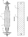
- Figure 1 is a cross sectional view of a rotor shaft 10 for a turbo-compressor that includes a shaft body 12 that is at least partially coated with a coating 14 of a dissimilar material according to an embodiment of the present disclosure.
- the shaft body 12 is operably connected to impellers 16a, 16b of low and high pressure compressors, respectively.
- the shaft body 12 has a generally unitary and/or solid body construction.
- the shaft body 12 may be a forged, machined, and/or molded piece of metal, such as steel, that provides and/or assists in attaining the desired rotor shaft body 12 size(s) and configuration.
- the coating 14 may be a metal that is dissimilar to the metal of the rotor shaft body 12.
- the rotor shaft body 12 is constructed from steel, while the coating 14 can be a copper or copper alloy material, such as, for example, copper chromium (UNS No. C18200) or copper chromium zirconium (UNS No. C18150), among other copper alloys.
- copper chromium UNS No. C18200
- copper chromium zirconium UNS No. C18150
- Other suitable coating materials as would be known to one skilled in the art are also contemplated by the present disclosure.
- the selection of the material for the coating 14 may be based on a variety of different criteria.
- the material for the coating 14 may be selected to improve the electrical connectivity characteristics of the rotor shaft 10 to levels beyond the connectively characteristics of the shaft body 12. Further, the material for the coating 14 may be selected based on the manner in which the coating 14 may be applied to and/or bonds with the material of the shaft body 12. Moreover, the coating 14 material may be selected based on the mechanical properties of the coating 14 and/or the properties of the bond between, or attachment of, the coating 14 and/to the shaft body 12.
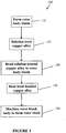
- FIG 3 is a flow diagram of a process 100 for manufacturing a rotor shaft 10 that includes a copper alloy coating 14 according to an embodiment of the present disclosure.
- a rotor body blank 18 is formed from a steel material. Such forming may include, for example, forging, casting, and/or machining the rotor body blank 18 to obtain a particular shape, size, and/or configuration.
- Figure 2 illustrates a rotor body blank 18 that has been formed, turned or otherwise milled to a diameter that is approximately equal to the largest diameter of the shaft body 12.
- a metal coating material that is to be used for the coating 14, such as, for example, an age-hardenable copper alloy, may be solution treated in preparation for age hardening after the bonding process.
- a copper alloy that is to be used for the coating 14 may undergo solution heat treatment.
- the copper alloy may be subjected to a high temperature soak, such as, for example, being subjected to temperatures of approximately 1450-1850 degrees Fahrenheit.
- the duration of the high temperature soak may be based on a variety of different factors, including, for example, the thickness of the copper alloy that is undergoing the solution treatment.
- the copper alloy may undergo the heat soak for approximately three minutes to approximately three hours.
- the high temperature soak may be followed by air cooling or quenching of the copper alloy, such as, for example, quenching the copper alloy in a water quench.
- the coating material may be in a relatively softer condition, and thus have improved ductility and plasticity characteristics.
- solution treating the coating material prior to bonding the coating material to the rotor body blank 18 the bonding performance and process reliability of the bond between the coating 14 and the rotor body blank 18 can be improved.
- solution treating the coating material, and thereby adjusting the relative hardness of the coating material to the material of the rotor body blank 18, may allow for the bonding process to be less prone to defects.
- the solution treatment process may increase the ductility of the coating material, thereby improving the plastic flow of the coating material.
- the bonding process may be more uniform and tolerant of parameter variations, including, for example, standoff gap and explosive velocity, among other parameters, which may thereby improve the reliability of the bond between the coating 14 and the rotor body blank 18.
- the metal coating material for the coating 14 may, while in the solution treated condition, be secured, such as, for example, bonded, to at least a portion of the rotor body blank 18 to provide a coating 14, as shown in Figure 2 .
- a copper alloy coating 14 may be bonded to the rotor body blank 18 using a low temperature, high integrity bonding process, such as, for example, via explosion welding or explosive bonding, diffusion bonding, or hot-isostatic pressing, among other bonding processes.
- the improved ductility and plasticity characteristics of the solution treated coating material may reduce the propensity for cracks forming in the coating material and/or along the coating 14 and rotor body blank 18 interface from or during the application and/or bonding of the coating material to the rotor body blank 18. Such reduction in cracking may improve the overall integrity of the resulting coating 14 and/or the bond between the coating 14 and the rotor body blank 18.
- the coating 14 on the rotor body blank 18 or shaft body 12 may be heat treated.
- a 'copper alloy coating 14 may undergo precipitation hardening or age hardening so that the copper alloy of the coating 14 attains a desired strength level, hardness, and/or electrical conductivity characteristics.
- Such heat treating of the coating 14 at step 140 may provide the coating 14 with at least a hardened outer portion that improves the ability of the coating 14 to resist creep and fatigue, including temperature dependent creep.
- the heat treatment process employed at step 140 may seek to attain a higher degree of coating 14 strength at the possible detriment of the ductility characteristics of the coating 14.
- the heat treatment process employed may be tailored to obtaining enhanced ductility characteristics of the coating 14 to the possible detriment of the hardness of the coating 14.
- the copper alloy may be elevated to the alloy's solution precipitation temperature so that chromium is precipitated out of the solid solution. More specifically, according to certain embodiments in which the copper alloy is C 18200, the copper alloy may be subjected to a temperature of approximately 795 to 935 degrees Fahrenheit for approximately two to four hours.
- the particular heat treatment process employed, and the associated procedure may also consider core properties of the steel of the rotor body blank 18 so that the properties or mechanical characteristics of the resulting shaft body 12 are not adversely impacted by the heat treatment process.
- age hardening of the coating 14 may occur at temperatures that seek to avoid tempering the steel material of the rotor shaft 10, and thereby prevent or minimize the age hardening process from adversely impacting core properties of the steel material of the rotor shaft 10, such as, for example, the strength of the steel, among other properties.
- the rotor body blank 18 having a coating 14 may be machined to the size, shape, and/or configuration of the rotor shaft 10. According to certain embodiments, such machining may remove at least a portion of the coating 14 that had been applied to the rotor body blank 18, as well as a portion of the steel material of the rotor body blank 18. Further, such machining may be performed before or after the coating 14 that has been applied to the rotor body blank 18 has been heat treated, such as before or after step 140. Further, according to certain embodiments in which the machining of step 150 occurs after the heat treatment process of step 140, the coating 14 remaining on the shaft body 12 may undergo further stress relieving treatment.
- the present disclosure includes a rotor shaft for a high speed motor, the rotor shaft comprising: a shaft body configured for rotational displacement during operation of the high speed motor, the shaft body being constructed from a steel material; and a coating secured to at least a portion of an outer surface of the shaft body, the coating configured to carry an induced electrical current for the rotational displacement of the shaft body, the coating being an alloy material, the alloy material of the coating and the steel material of the shaft body being dissimilar materials.
- the present disclosure includes a rotor shaft, wherein the alloy material is a copper alloy; wherein the coating is secured to the shaft body by a low temperature bonding process; wherein the coating is secured to the shaft body by explosion welding; wherein the coating is an age hardened material; wherein the shaft body has a unitary construction; wherein the rotor shaft is configured to operate at a tip speed greater than 300 meters/second; wherein the rotor shaft is configured for use with a turbo-compressor that is configured for air compression; wherein the copper alloy is copper chromium; and wherein the copper alloy is copper chromium zirconium.
- the present disclosure includes a method for manufacturing a rotor shaft for a high speed motor, the method comprising: forming a rotor body blank from a steel material; solution treating an alloy material, the alloy material and the steel material of the rotor body blank being different materials; securing the solution treated alloy material to at least a portion of the rotor body blank to provide a coating; heat treating the coating when the coating is secured to the rotor body blank, the heat treating process adapted to minimize the loss of a core property of the steel material of the rotor body blank; and machining the rotor body blank and the coating to form the rotor shaft, the rotor shaft configured for operation in a high speed motor.
- the present disclosure includes a method for manufacturing a rotor shaft for a high speed motor, wherein the alloy material is a copper alloy; wherein the step of securing the alloy material includes using a low temperature welding process; wherein the step of securing the alloy material includes using explosion welding to cover at least a portion of the rotor body blank with the alloy material; wherein the step of heat treating the coating includes age hardening the coating; further including the step of stress relieving the coating; wherein the rotor shaft is manufactured to operate at a tip speed greater than 300 meters/second; wherein the step of machining the rotor body blank and the coating includes forming the rotor shaft for use with a turbo-compressor that is configured for air compression; wherein the step of heat treating the coating includes enhancing the ductility of the coating; wherein the step of heat treating the coating includes enhancing the hardness of the coating; and wherein the step of heat treating includes enhancing the temperature dependent creep resistance of the coating.
Landscapes
- Engineering & Computer Science (AREA)
- Chemical & Material Sciences (AREA)
- Mechanical Engineering (AREA)
- General Engineering & Computer Science (AREA)
- Power Engineering (AREA)
- Materials Engineering (AREA)
- Organic Chemistry (AREA)
- Manufacturing & Machinery (AREA)
- Wood Science & Technology (AREA)
- Life Sciences & Earth Sciences (AREA)
- Chemical Kinetics & Catalysis (AREA)
- Metallurgy (AREA)
- Structures Of Non-Positive Displacement Pumps (AREA)
- Turbine Rotor Nozzle Sealing (AREA)
- Manufacture Of Motors, Generators (AREA)
Claims (15)
- Eine Rotorwelle (10) für einen Hochgeschwindigkeitsmotor, wobei die Rotorwelle (10) Folgendes beinhaltet:einen Wellenkörper (12), der zur Drehverlagerung während des Betriebs des Hochgeschwindigkeitsmotors konfiguriert ist, wobei der Wellenkörper (12) aus einem Stahlmaterial konstruiert ist; undeine Beschichtung (14), die an mindestens einem Abschnitt einer äußeren Oberfläche des Wellenkörpers (12) fixiert ist, wobei die Beschichtung (14) konfiguriert ist, um einen induzierten elektrischen Strom für die Drehverlagerung des Wellenkörpers (12) zu leiten, wobei die Beschichtung (14) ein Legierungsmaterial ist, wobei das Legierungsmaterial der Beschichtung (14) und das Stahlmaterial des Wellenkörpers (12) ungleiche Materialien sind, dadurch gekennzeichnet, dassdie Beschichtung (14) vordem Fixieren an dem Wellenkörper (12) lösungsgeglüht wird, sodass die Duktilität und Plastizität der Beschichtung verbessert werden, und dadurch, dass die Beschichtung (14) nach dem Fixieren an dem Wellenkörper (12) wärmebehandelt wird, sodass der Verlust einer Kerneigenschaft des Stahlmaterials des Rotorkörperrohteils (18) minimiert wird.
- Rotorwelle (10) gemäß Anspruch 1, wobei das Legierungsmaterial eine Kupferlegierung ist.
- Rotorwelle (10) gemäß Anspruch 2, wobei die Beschichtung (14) durch einen Verbindungsprozess niedriger Temperatur an dem Wellenkörper (12) fixiert wird; oder wobei die Beschichtung (14) durch Sprengschweißen an dem Wellenkörper (12) fixiert wird.
- Rotorwelle (10) gemäß Anspruch 3, wobei die Beschichtung (14) ein ausgehärtetes Material ist.
- Rotorwelle (10) gemäß Anspruch 4, wobei der Wellenkörper (12) eine einheitliche Konstruktion aufweist.
- Rotorwelle (10) gemäß Anspruch 5, wobei die Rotorwelle (10) zur Verwendung mit einem Turboverdichter konfiguriert ist, der zur Luftverdichtung konfiguriert ist.
- Rotorwelle (10) gemäß Anspruch 6, wobei die Kupferlegierung Kupfer-Chrom ist; oder wobei die Kupferlegierung Kupfer-Chrom-Zirconium ist.
- Ein Verfahren zum Herstellen einer Rotorwelle (10) für einen Hochgeschwindigkeitsmotor, wobei das Verfahren Folgendes beinhaltet:Bilden eines Rotorkörperrohteils (18) aus einem Stahlmaterial;Lösungsglühen eines Legierungsmaterials, wobei der Lösungsglühprozess angepasst ist, um die Duktilität und Plastizität des Legierungsmaterials zu verbessern, wobei das Legierungsmaterial konfiguriert ist, um einen induzierten elektrischen Strom für die Drehverlagerung des Wellenkörpers (12) der Drehwelle zu leiten, und wobei das Legierungsmaterial und das Stahlmaterial des Rotorkörperrohteils (18) unterschiedliche Materialien sind;Fixieren des Legierungsmaterials nach dem Lösungsglühen an mindestens einem Abschnitt des Rotorkörperrohteils (18), um eine Beschichtung (14) bereitzustellen; Wärmebehandeln der Beschichtung (14), wenn die Beschichtung (14) an dem Rotorkörperrohteil (18) fixiert ist, wobei der Wärmebehandlungsprozess angepasst ist,um den Verlust einer Kerneigenschaft des Stahlmaterials des Rotorkörperrohteils (18) zu minimieren; undmaschinelles Bearbeiten des Rotorkörperrohteils (18) und der Beschichtung (14), um die Rotorwelle (10) zu bilden, wobei die Rotorwelle (10) zum Betrieb in einem Hochgeschwindigkeitsmotor konfiguriert ist.
- Verfahren gemäß Anspruch 8, wobei das Legierungsmaterial eine Kupferlegierung ist.
- Verfahren gemäß Anspruch 9, wobei der Schritt des Fixierens des Legierungsmaterials das Verwenden eines Schweißprozesses niedriger Temperatur umfasst; oder
wobei der Schritt des Fixierens des Legierungsmaterials das Verwenden von Sprengschweißen zum Bedecken mindestens eines Abschnitts des Rotorkörperrohteils (18) mit dem Legierungsmaterial umfasst. - Verfahren gemäß Anspruch 10, wobei der Schritt des Wärmebehandelns der Beschichtung (14) das Aushärten der Beschichtung (14) umfasst.
- Verfahren gemäß Anspruch 11, das ferner den Schritt des Entspannens der Beschichtung (14) umfasst.
- Rotorwelle (10) gemäß Anspruch 5 oder Verfahren gemäß Anspruch 12, wobei die Rotorwelle (10) hergestellt wird, um mit einer Blattspitzengeschwindigkeit von mehr als 300 Metern/Sekunde betrieben zu werden.
- Verfahren gemäß Anspruch 12, wobei der Schritt des maschinellen Bearbeitens des Rotorkörperrohteils (18) und des Beschichtens (14) das Bilden der Rotorwelle (10) zur Verwendung mit einem Turboverdichter, der zur Luftverdichtung konfiguriert ist, umfasst.
- Verfahren gemäß Anspruch 14, wobei der Schritt des Wärmebehandelns der Beschichtung (14) das Steigern der Duktilität der Beschichtung (14) umfasst; oder wobei der Schritt des Wärmebehandelns der Beschichtung (14) das Steigern der Härte der Beschichtung (14) umfasst; oder
wobei der Schritt des Wärmebehandelns das Steigern des temperaturabhängigen Kriechwiderstands der Beschichtung (14) umfasst.
Applications Claiming Priority (2)
| Application Number | Priority Date | Filing Date | Title |
|---|---|---|---|
| US201462098818P | 2014-12-31 | 2014-12-31 | |
| US14/973,121 US10253649B2 (en) | 2014-12-31 | 2015-12-17 | Rotor construction for high speed motors |
Publications (2)
| Publication Number | Publication Date |
|---|---|
| EP3040384A1 EP3040384A1 (de) | 2016-07-06 |
| EP3040384B1 true EP3040384B1 (de) | 2021-03-10 |
Family
ID=55085432
Family Applications (1)
| Application Number | Title | Priority Date | Filing Date |
|---|---|---|---|
| EP15003688.7A Revoked EP3040384B1 (de) | 2014-12-31 | 2015-12-29 | Rotorkonstruktion für hochgeschwindigkeitsmotoren und herstellungsmethode |
Country Status (3)
| Country | Link |
|---|---|
| US (3) | US10253649B2 (de) |
| EP (1) | EP3040384B1 (de) |
| CN (1) | CN106148956A (de) |
Families Citing this family (8)
| Publication number | Priority date | Publication date | Assignee | Title |
|---|---|---|---|---|
| US10253649B2 (en) * | 2014-12-31 | 2019-04-09 | Ingersoll-Rand Company | Rotor construction for high speed motors |
| CN107546890B (zh) | 2016-06-28 | 2021-07-16 | 特灵国际有限公司 | 谐波分流的电机、方法、ac电机系统及可变速驱动系统 |
| US10826357B2 (en) | 2017-06-28 | 2020-11-03 | Trane International Inc. | Harmonic shunting electric motor with faceted shaft for improved torque transmission |
| FR3086121B1 (fr) | 2018-09-19 | 2020-10-16 | Ge Energy Power Conversion Technology Ltd | Rotor pour machine electrique asynchrone a arbre non traversant |
| EP3629452A1 (de) | 2018-09-28 | 2020-04-01 | Siemens Aktiengesellschaft | Verfahren zur herstellung eines rotors für eine elektrische rotierende maschine |
| CN109995197B (zh) * | 2019-04-30 | 2020-04-07 | 成都金士力科技有限公司 | 一种用于装配高低温真空步进电机的方法 |
| CN113224900B (zh) * | 2021-05-10 | 2025-07-04 | 鑫磊压缩机股份有限公司 | 一种无推力盘的磁悬浮高速异步电机 |
| CN118242307A (zh) * | 2024-03-28 | 2024-06-25 | 泰尔重工股份有限公司 | 一种一体式核电泵轴及其新轴加工工艺、旧轴修复工艺 |
Citations (14)
| Publication number | Priority date | Publication date | Assignee | Title |
|---|---|---|---|---|
| FR1363147A (fr) | 1963-01-15 | 1964-06-12 | Texas Instruments Inc | Produit métallique composite et procédé de fabrication de ce produit |
| GB1034862A (en) | 1961-02-06 | 1966-07-06 | Texas Instruments Inc | Composite metal product and method of producing the same |
| FR1466192A (fr) | 1966-01-31 | 1967-01-13 | Revere Copper & Brass Inc | Procédé pour réunir l'aluminium à l'acier inoxydable |
| US3702497A (en) | 1971-01-07 | 1972-11-14 | Polymetallurgical Corp | Manufacture of clad metals |
| US4577128A (en) | 1980-12-11 | 1986-03-18 | Northern Engineering Industries, Plc | Induction motors |
| US4679314A (en) | 1985-12-23 | 1987-07-14 | General Electric Company | Method for making a fluid cooled acyclic generator rotor |
| US4724013A (en) | 1984-06-08 | 1988-02-09 | Brush Wellman, Inc. | Processing of copper alloys and product |
| US20060131981A1 (en) | 2004-12-20 | 2006-06-22 | General Electric Company | Electrical machine with improved loss characteristics and method of making same |
| EP2065116A1 (de) | 2007-10-15 | 2009-06-03 | Wickeder Westfalenstahl GmbH | Verbundwerkstoff, insbesondere Reibverbundwerkstoff und Verfahren zur Herstellung eines Verbundwerkstoffs |
| US20090250144A1 (en) | 2003-06-09 | 2009-10-08 | Sumitomo Light Metal Industries, Ltd. | Method of joining heat-treatable aluminum alloy members by friction stir welding |
| US20100215526A1 (en) | 2007-05-14 | 2010-08-26 | Sundyne Corporation | Electric machine with air cooling system |
| US20110260561A1 (en) | 2010-01-11 | 2011-10-27 | Heitmann Arnold M | Induction motor |
| US20120186706A1 (en) | 2011-01-24 | 2012-07-26 | GM Global Technology Operations LLC | Stamping of age-hardenable aluminum alloy sheets |
| US20140306460A1 (en) | 2013-04-16 | 2014-10-16 | Icr Turbine Engine Corporation | High speed direct drive generator for a gas turbine engine |
Family Cites Families (7)
| Publication number | Priority date | Publication date | Assignee | Title |
|---|---|---|---|---|
| JPS60114558A (ja) * | 1983-11-22 | 1985-06-21 | Ngk Insulators Ltd | 時効硬化性チタニウム銅合金展伸材の製造法 |
| US5642853A (en) | 1995-08-30 | 1997-07-01 | General Electric Company | Method for bonding steel to copper |
| US5801470A (en) | 1996-12-19 | 1998-09-01 | General Electric Company | Rotors with retaining cylinders and reduced harmonic field effect losses |
| US6362552B1 (en) | 1999-07-06 | 2002-03-26 | Gregory C. Jeppesen | Electric motor rotor |
| EP1750347B1 (de) | 2001-03-30 | 2011-06-15 | Sanyo Electric Co., Ltd. | Synchronmaschine |
| US7538458B2 (en) | 2001-07-13 | 2009-05-26 | Voith Patent Gmbh | Construction and method of an electric motor drive |
| US10253649B2 (en) * | 2014-12-31 | 2019-04-09 | Ingersoll-Rand Company | Rotor construction for high speed motors |
-
2015
- 2015-12-17 US US14/973,121 patent/US10253649B2/en not_active Expired - Fee Related
- 2015-12-29 EP EP15003688.7A patent/EP3040384B1/de not_active Revoked
- 2015-12-30 CN CN201511010786.6A patent/CN106148956A/zh active Pending
-
2019
- 2019-04-08 US US16/377,950 patent/US11125107B2/en not_active Expired - Fee Related
-
2021
- 2021-09-21 US US17/480,642 patent/US20220074317A1/en not_active Abandoned
Patent Citations (14)
| Publication number | Priority date | Publication date | Assignee | Title |
|---|---|---|---|---|
| GB1034862A (en) | 1961-02-06 | 1966-07-06 | Texas Instruments Inc | Composite metal product and method of producing the same |
| FR1363147A (fr) | 1963-01-15 | 1964-06-12 | Texas Instruments Inc | Produit métallique composite et procédé de fabrication de ce produit |
| FR1466192A (fr) | 1966-01-31 | 1967-01-13 | Revere Copper & Brass Inc | Procédé pour réunir l'aluminium à l'acier inoxydable |
| US3702497A (en) | 1971-01-07 | 1972-11-14 | Polymetallurgical Corp | Manufacture of clad metals |
| US4577128A (en) | 1980-12-11 | 1986-03-18 | Northern Engineering Industries, Plc | Induction motors |
| US4724013A (en) | 1984-06-08 | 1988-02-09 | Brush Wellman, Inc. | Processing of copper alloys and product |
| US4679314A (en) | 1985-12-23 | 1987-07-14 | General Electric Company | Method for making a fluid cooled acyclic generator rotor |
| US20090250144A1 (en) | 2003-06-09 | 2009-10-08 | Sumitomo Light Metal Industries, Ltd. | Method of joining heat-treatable aluminum alloy members by friction stir welding |
| US20060131981A1 (en) | 2004-12-20 | 2006-06-22 | General Electric Company | Electrical machine with improved loss characteristics and method of making same |
| US20100215526A1 (en) | 2007-05-14 | 2010-08-26 | Sundyne Corporation | Electric machine with air cooling system |
| EP2065116A1 (de) | 2007-10-15 | 2009-06-03 | Wickeder Westfalenstahl GmbH | Verbundwerkstoff, insbesondere Reibverbundwerkstoff und Verfahren zur Herstellung eines Verbundwerkstoffs |
| US20110260561A1 (en) | 2010-01-11 | 2011-10-27 | Heitmann Arnold M | Induction motor |
| US20120186706A1 (en) | 2011-01-24 | 2012-07-26 | GM Global Technology Operations LLC | Stamping of age-hardenable aluminum alloy sheets |
| US20140306460A1 (en) | 2013-04-16 | 2014-10-16 | Icr Turbine Engine Corporation | High speed direct drive generator for a gas turbine engine |
Non-Patent Citations (1)
| Title |
|---|
| KHANZADEH M. R., AKBARI MOUSAVI S. A. A., AMADEH A., LIAGHAT G. H.: "Correlation Between Numerical Finite Element Simulation and Experiments for Explosive Cladding of Nickel Base Super Alloy on Hot Tool Steel : Correlation Between Numerical Finite Element Simulation and Experiments for Explosive Cladding", STRAIN., BLACKWELL PUBLISHING LTD., MALDEN, MA., US, vol. 48, no. 4, 1 August 2012 (2012-08-01), US , pages 342 - 355, XP055910149, ISSN: 0039-2103, DOI: 10.1111/j.1475-1305.2011.00828.x |
Also Published As
| Publication number | Publication date |
|---|---|
| EP3040384A1 (de) | 2016-07-06 |
| CN106148956A (zh) | 2016-11-23 |
| US11125107B2 (en) | 2021-09-21 |
| US20160186603A1 (en) | 2016-06-30 |
| US20200072079A1 (en) | 2020-03-05 |
| US10253649B2 (en) | 2019-04-09 |
| US20220074317A1 (en) | 2022-03-10 |
Similar Documents
| Publication | Publication Date | Title |
|---|---|---|
| US11125107B2 (en) | Rotor construction for high speed motors | |
| CN101844271A (zh) | 钛铝合金涡轮与42CrMo调质钢轴的摩擦焊接方法 | |
| EP2679333B1 (de) | Herstellungsverfahren für ein laufrad | |
| JP2018506647A (ja) | 流導コンポーネント | |
| JP5411120B2 (ja) | チタン合金製タービン翼 | |
| JP5472630B2 (ja) | 摺動部材とその製造方法 | |
| EP3309264A1 (de) | Hybridkomponente und verfahren zur herstellung | |
| JP5653653B2 (ja) | 回転機械部品用素材の製造方法及び回転機械部品の製造方法、回転機械部品用素材、回転機械部品並びに遠心圧縮機 | |
| JPH0329031B2 (de) | ||
| JP5428482B2 (ja) | 界磁極用磁石体の製造方法及び永久磁石型電動機 | |
| CN105658374A (zh) | 耐疲劳的涡轮贯穿螺栓 | |
| KR20220045210A (ko) | 로터, 로터의 설계 방법 및 로터의 제조 방법 | |
| EP3247027B1 (de) | Verfahren zur herstellung eines lamellenstapels zur verwendung in einer elektrischen maschine | |
| JP7447310B2 (ja) | ロータの製造方法 | |
| CN107559049B (zh) | 一种高效汽轮机叶片 | |
| JPH01182505A (ja) | タービン動翼の製作方法 | |
| JPS62113801A (ja) | タ−ビン翼 | |
| JP2007049834A (ja) | 永久磁石形回転子とその製造方法およびサーボモータ | |
| JP5422583B2 (ja) | インペラの製造方法 | |
| CN117588438A (zh) | 抗跌落防轴承电腐蚀风扇及其制造工艺 | |
| JP2008298202A (ja) | 等速自在継手、外側継手部材、及び外側継手部材の製造方法 | |
| PL232251B1 (pl) | Sposób wykonania koła wirnikowego sprężarki promieniowej | |
| JP5422584B2 (ja) | インペラの製造方法 | |
| JPS62165510A (ja) | タ−ビン翼 | |
| JP2001355406A (ja) | タービン動翼の連結構造 |
Legal Events
| Date | Code | Title | Description |
|---|---|---|---|
| PUAI | Public reference made under article 153(3) epc to a published international application that has entered the european phase |
Free format text: ORIGINAL CODE: 0009012 |
|
| 17P | Request for examination filed |
Effective date: 20151229 |
|
| AK | Designated contracting states |
Kind code of ref document: A1 Designated state(s): AL AT BE BG CH CY CZ DE DK EE ES FI FR GB GR HR HU IE IS IT LI LT LU LV MC MK MT NL NO PL PT RO RS SE SI SK SM TR |
|
| AX | Request for extension of the european patent |
Extension state: BA ME |
|
| STAA | Information on the status of an ep patent application or granted ep patent |
Free format text: STATUS: EXAMINATION IS IN PROGRESS |
|
| 17Q | First examination report despatched |
Effective date: 20180622 |
|
| GRAP | Despatch of communication of intention to grant a patent |
Free format text: ORIGINAL CODE: EPIDOSNIGR1 |
|
| STAA | Information on the status of an ep patent application or granted ep patent |
Free format text: STATUS: GRANT OF PATENT IS INTENDED |
|
| RAP1 | Party data changed (applicant data changed or rights of an application transferred) |
Owner name: INGERSOLL-RAND INDUSTRIAL U.S., INC. |
|
| INTG | Intention to grant announced |
Effective date: 20200424 |
|
| GRAJ | Information related to disapproval of communication of intention to grant by the applicant or resumption of examination proceedings by the epo deleted |
Free format text: ORIGINAL CODE: EPIDOSDIGR1 |
|
| STAA | Information on the status of an ep patent application or granted ep patent |
Free format text: STATUS: EXAMINATION IS IN PROGRESS |
|
| GRAP | Despatch of communication of intention to grant a patent |
Free format text: ORIGINAL CODE: EPIDOSNIGR1 |
|
| INTC | Intention to grant announced (deleted) | ||
| STAA | Information on the status of an ep patent application or granted ep patent |
Free format text: STATUS: GRANT OF PATENT IS INTENDED |
|
| INTG | Intention to grant announced |
Effective date: 20201001 |
|
| GRAS | Grant fee paid |
Free format text: ORIGINAL CODE: EPIDOSNIGR3 |
|
| GRAA | (expected) grant |
Free format text: ORIGINAL CODE: 0009210 |
|
| STAA | Information on the status of an ep patent application or granted ep patent |
Free format text: STATUS: THE PATENT HAS BEEN GRANTED |
|
| AK | Designated contracting states |
Kind code of ref document: B1 Designated state(s): AL AT BE BG CH CY CZ DE DK EE ES FI FR GB GR HR HU IE IS IT LI LT LU LV MC MK MT NL NO PL PT RO RS SE SI SK SM TR |
|
| REG | Reference to a national code |
Ref country code: GB Ref legal event code: FG4D |
|
| REG | Reference to a national code |
Ref country code: AT Ref legal event code: REF Ref document number: 1369779 Country of ref document: AT Kind code of ref document: T Effective date: 20210315 Ref country code: CH Ref legal event code: EP |
|
| REG | Reference to a national code |
Ref country code: IE Ref legal event code: FG4D |
|
| REG | Reference to a national code |
Ref country code: DE Ref legal event code: R096 Ref document number: 602015066562 Country of ref document: DE |
|
| REG | Reference to a national code |
Ref country code: FI Ref legal event code: FGE |
|
| REG | Reference to a national code |
Ref country code: LT Ref legal event code: MG9D |
|
| PG25 | Lapsed in a contracting state [announced via postgrant information from national office to epo] |
Ref country code: LT Free format text: LAPSE BECAUSE OF FAILURE TO SUBMIT A TRANSLATION OF THE DESCRIPTION OR TO PAY THE FEE WITHIN THE PRESCRIBED TIME-LIMIT Effective date: 20210310 Ref country code: GR Free format text: LAPSE BECAUSE OF FAILURE TO SUBMIT A TRANSLATION OF THE DESCRIPTION OR TO PAY THE FEE WITHIN THE PRESCRIBED TIME-LIMIT Effective date: 20210611 Ref country code: HR Free format text: LAPSE BECAUSE OF FAILURE TO SUBMIT A TRANSLATION OF THE DESCRIPTION OR TO PAY THE FEE WITHIN THE PRESCRIBED TIME-LIMIT Effective date: 20210310 Ref country code: BG Free format text: LAPSE BECAUSE OF FAILURE TO SUBMIT A TRANSLATION OF THE DESCRIPTION OR TO PAY THE FEE WITHIN THE PRESCRIBED TIME-LIMIT Effective date: 20210610 Ref country code: NO Free format text: LAPSE BECAUSE OF FAILURE TO SUBMIT A TRANSLATION OF THE DESCRIPTION OR TO PAY THE FEE WITHIN THE PRESCRIBED TIME-LIMIT Effective date: 20210610 |
|
| REG | Reference to a national code |
Ref country code: AT Ref legal event code: MK05 Ref document number: 1369779 Country of ref document: AT Kind code of ref document: T Effective date: 20210310 |
|
| REG | Reference to a national code |
Ref country code: NL Ref legal event code: MP Effective date: 20210310 |
|
| PG25 | Lapsed in a contracting state [announced via postgrant information from national office to epo] |
Ref country code: SE Free format text: LAPSE BECAUSE OF FAILURE TO SUBMIT A TRANSLATION OF THE DESCRIPTION OR TO PAY THE FEE WITHIN THE PRESCRIBED TIME-LIMIT Effective date: 20210310 Ref country code: RS Free format text: LAPSE BECAUSE OF FAILURE TO SUBMIT A TRANSLATION OF THE DESCRIPTION OR TO PAY THE FEE WITHIN THE PRESCRIBED TIME-LIMIT Effective date: 20210310 Ref country code: LV Free format text: LAPSE BECAUSE OF FAILURE TO SUBMIT A TRANSLATION OF THE DESCRIPTION OR TO PAY THE FEE WITHIN THE PRESCRIBED TIME-LIMIT Effective date: 20210310 |
|
| PG25 | Lapsed in a contracting state [announced via postgrant information from national office to epo] |
Ref country code: NL Free format text: LAPSE BECAUSE OF FAILURE TO SUBMIT A TRANSLATION OF THE DESCRIPTION OR TO PAY THE FEE WITHIN THE PRESCRIBED TIME-LIMIT Effective date: 20210310 |
|
| PG25 | Lapsed in a contracting state [announced via postgrant information from national office to epo] |
Ref country code: SM Free format text: LAPSE BECAUSE OF FAILURE TO SUBMIT A TRANSLATION OF THE DESCRIPTION OR TO PAY THE FEE WITHIN THE PRESCRIBED TIME-LIMIT Effective date: 20210310 Ref country code: AT Free format text: LAPSE BECAUSE OF FAILURE TO SUBMIT A TRANSLATION OF THE DESCRIPTION OR TO PAY THE FEE WITHIN THE PRESCRIBED TIME-LIMIT Effective date: 20210310 Ref country code: EE Free format text: LAPSE BECAUSE OF FAILURE TO SUBMIT A TRANSLATION OF THE DESCRIPTION OR TO PAY THE FEE WITHIN THE PRESCRIBED TIME-LIMIT Effective date: 20210310 Ref country code: CZ Free format text: LAPSE BECAUSE OF FAILURE TO SUBMIT A TRANSLATION OF THE DESCRIPTION OR TO PAY THE FEE WITHIN THE PRESCRIBED TIME-LIMIT Effective date: 20210310 |
|
| PGFP | Annual fee paid to national office [announced via postgrant information from national office to epo] |
Ref country code: FI Payment date: 20210927 Year of fee payment: 7 |
|
| PG25 | Lapsed in a contracting state [announced via postgrant information from national office to epo] |
Ref country code: IS Free format text: LAPSE BECAUSE OF FAILURE TO SUBMIT A TRANSLATION OF THE DESCRIPTION OR TO PAY THE FEE WITHIN THE PRESCRIBED TIME-LIMIT Effective date: 20210710 Ref country code: RO Free format text: LAPSE BECAUSE OF FAILURE TO SUBMIT A TRANSLATION OF THE DESCRIPTION OR TO PAY THE FEE WITHIN THE PRESCRIBED TIME-LIMIT Effective date: 20210310 Ref country code: SK Free format text: LAPSE BECAUSE OF FAILURE TO SUBMIT A TRANSLATION OF THE DESCRIPTION OR TO PAY THE FEE WITHIN THE PRESCRIBED TIME-LIMIT Effective date: 20210310 Ref country code: PT Free format text: LAPSE BECAUSE OF FAILURE TO SUBMIT A TRANSLATION OF THE DESCRIPTION OR TO PAY THE FEE WITHIN THE PRESCRIBED TIME-LIMIT Effective date: 20210712 Ref country code: PL Free format text: LAPSE BECAUSE OF FAILURE TO SUBMIT A TRANSLATION OF THE DESCRIPTION OR TO PAY THE FEE WITHIN THE PRESCRIBED TIME-LIMIT Effective date: 20210310 Ref country code: ES Free format text: LAPSE BECAUSE OF FAILURE TO SUBMIT A TRANSLATION OF THE DESCRIPTION OR TO PAY THE FEE WITHIN THE PRESCRIBED TIME-LIMIT Effective date: 20210310 |
|
| REG | Reference to a national code |
Ref country code: DE Ref legal event code: R026 Ref document number: 602015066562 Country of ref document: DE |
|
| PLBI | Opposition filed |
Free format text: ORIGINAL CODE: 0009260 |
|
| PLAX | Notice of opposition and request to file observation + time limit sent |
Free format text: ORIGINAL CODE: EPIDOSNOBS2 |
|
| REG | Reference to a national code |
Ref country code: FI Ref legal event code: MDE Opponent name: SIEMENS AKTIENGESELLSCHAFT |
|
| 26 | Opposition filed |
Opponent name: SIEMENS AKTIENGESELLSCHAFT Effective date: 20211210 |
|
| PG25 | Lapsed in a contracting state [announced via postgrant information from national office to epo] |
Ref country code: DK Free format text: LAPSE BECAUSE OF FAILURE TO SUBMIT A TRANSLATION OF THE DESCRIPTION OR TO PAY THE FEE WITHIN THE PRESCRIBED TIME-LIMIT Effective date: 20210310 Ref country code: AL Free format text: LAPSE BECAUSE OF FAILURE TO SUBMIT A TRANSLATION OF THE DESCRIPTION OR TO PAY THE FEE WITHIN THE PRESCRIBED TIME-LIMIT Effective date: 20210310 |
|
| PGFP | Annual fee paid to national office [announced via postgrant information from national office to epo] |
Ref country code: GB Payment date: 20211026 Year of fee payment: 7 Ref country code: DE Payment date: 20210927 Year of fee payment: 7 |
|
| PG25 | Lapsed in a contracting state [announced via postgrant information from national office to epo] |
Ref country code: SI Free format text: LAPSE BECAUSE OF FAILURE TO SUBMIT A TRANSLATION OF THE DESCRIPTION OR TO PAY THE FEE WITHIN THE PRESCRIBED TIME-LIMIT Effective date: 20210310 |
|
| PGFP | Annual fee paid to national office [announced via postgrant information from national office to epo] |
Ref country code: IT Payment date: 20210927 Year of fee payment: 7 Ref country code: FR Payment date: 20211025 Year of fee payment: 7 |
|
| PG25 | Lapsed in a contracting state [announced via postgrant information from national office to epo] |
Ref country code: IS Free format text: LAPSE BECAUSE OF FAILURE TO SUBMIT A TRANSLATION OF THE DESCRIPTION OR TO PAY THE FEE WITHIN THE PRESCRIBED TIME-LIMIT Effective date: 20210710 |
|
| PG25 | Lapsed in a contracting state [announced via postgrant information from national office to epo] |
Ref country code: MC Free format text: LAPSE BECAUSE OF FAILURE TO SUBMIT A TRANSLATION OF THE DESCRIPTION OR TO PAY THE FEE WITHIN THE PRESCRIBED TIME-LIMIT Effective date: 20210310 |
|
| REG | Reference to a national code |
Ref country code: CH Ref legal event code: PL |
|
| REG | Reference to a national code |
Ref country code: BE Ref legal event code: MM Effective date: 20211231 |
|
| PG25 | Lapsed in a contracting state [announced via postgrant information from national office to epo] |
Ref country code: LU Free format text: LAPSE BECAUSE OF NON-PAYMENT OF DUE FEES Effective date: 20211229 Ref country code: IE Free format text: LAPSE BECAUSE OF NON-PAYMENT OF DUE FEES Effective date: 20211229 |
|
| PG25 | Lapsed in a contracting state [announced via postgrant information from national office to epo] |
Ref country code: BE Free format text: LAPSE BECAUSE OF NON-PAYMENT OF DUE FEES Effective date: 20211231 |
|
| PG25 | Lapsed in a contracting state [announced via postgrant information from national office to epo] |
Ref country code: LI Free format text: LAPSE BECAUSE OF NON-PAYMENT OF DUE FEES Effective date: 20211231 Ref country code: CH Free format text: LAPSE BECAUSE OF NON-PAYMENT OF DUE FEES Effective date: 20211231 |
|
| PLAB | Opposition data, opponent's data or that of the opponent's representative modified |
Free format text: ORIGINAL CODE: 0009299OPPO |
|
| R26 | Opposition filed (corrected) |
Opponent name: SIEMENS AKTIENGESELLSCHAFT Effective date: 20211210 |
|
| PG25 | Lapsed in a contracting state [announced via postgrant information from national office to epo] |
Ref country code: HU Free format text: LAPSE BECAUSE OF FAILURE TO SUBMIT A TRANSLATION OF THE DESCRIPTION OR TO PAY THE FEE WITHIN THE PRESCRIBED TIME-LIMIT; INVALID AB INITIO Effective date: 20151229 |
|
| P01 | Opt-out of the competence of the unified patent court (upc) registered |
Effective date: 20230523 |
|
| PG25 | Lapsed in a contracting state [announced via postgrant information from national office to epo] |
Ref country code: CY Free format text: LAPSE BECAUSE OF FAILURE TO SUBMIT A TRANSLATION OF THE DESCRIPTION OR TO PAY THE FEE WITHIN THE PRESCRIBED TIME-LIMIT Effective date: 20210310 |
|
| REG | Reference to a national code |
Ref country code: DE Ref legal event code: R119 Ref document number: 602015066562 Country of ref document: DE |
|
| GBPC | Gb: european patent ceased through non-payment of renewal fee |
Effective date: 20221229 |
|
| REG | Reference to a national code |
Ref country code: DE Ref legal event code: R103 Ref document number: 602015066562 Country of ref document: DE Ref country code: DE Ref legal event code: R064 Ref document number: 602015066562 Country of ref document: DE |
|
| PG25 | Lapsed in a contracting state [announced via postgrant information from national office to epo] |
Ref country code: GB Free format text: LAPSE BECAUSE OF NON-PAYMENT OF DUE FEES Effective date: 20221229 Ref country code: DE Free format text: LAPSE BECAUSE OF NON-PAYMENT OF DUE FEES Effective date: 20230701 |
|
| PG25 | Lapsed in a contracting state [announced via postgrant information from national office to epo] |
Ref country code: FR Free format text: LAPSE BECAUSE OF NON-PAYMENT OF DUE FEES Effective date: 20221231 |
|
| RDAF | Communication despatched that patent is revoked |
Free format text: ORIGINAL CODE: EPIDOSNREV1 |
|
| PG25 | Lapsed in a contracting state [announced via postgrant information from national office to epo] |
Ref country code: IT Free format text: LAPSE BECAUSE OF NON-PAYMENT OF DUE FEES Effective date: 20221229 |
|
| RDAG | Patent revoked |
Free format text: ORIGINAL CODE: 0009271 |
|
| STAA | Information on the status of an ep patent application or granted ep patent |
Free format text: STATUS: PATENT REVOKED |
|
| REG | Reference to a national code |
Ref country code: CH Ref legal event code: PL |
|
| 27W | Patent revoked |
Effective date: 20231012 |
|
| PG25 | Lapsed in a contracting state [announced via postgrant information from national office to epo] |
Ref country code: MK Free format text: LAPSE BECAUSE OF FAILURE TO SUBMIT A TRANSLATION OF THE DESCRIPTION OR TO PAY THE FEE WITHIN THE PRESCRIBED TIME-LIMIT Effective date: 20210310 Ref country code: FI Free format text: LAPSE BECAUSE OF NON-PAYMENT OF DUE FEES Effective date: 20221229 |
|
| PG25 | Lapsed in a contracting state [announced via postgrant information from national office to epo] |
Ref country code: MT Free format text: LAPSE BECAUSE OF FAILURE TO SUBMIT A TRANSLATION OF THE DESCRIPTION OR TO PAY THE FEE WITHIN THE PRESCRIBED TIME-LIMIT Effective date: 20210310 |
|
| PG25 | Lapsed in a contracting state [announced via postgrant information from national office to epo] |
Ref country code: TR Free format text: LAPSE BECAUSE OF FAILURE TO SUBMIT A TRANSLATION OF THE DESCRIPTION OR TO PAY THE FEE WITHIN THE PRESCRIBED TIME-LIMIT Effective date: 20210310 |