EP3040160A1 - Backing pad with slots for sanding disks with multiple holes - Google Patents
Backing pad with slots for sanding disks with multiple holes Download PDFInfo
- Publication number
- EP3040160A1 EP3040160A1 EP15708912.9A EP15708912A EP3040160A1 EP 3040160 A1 EP3040160 A1 EP 3040160A1 EP 15708912 A EP15708912 A EP 15708912A EP 3040160 A1 EP3040160 A1 EP 3040160A1
- Authority
- EP
- European Patent Office
- Prior art keywords
- slots
- holes
- backing pad
- suction
- disc
- Prior art date
- Legal status (The legal status is an assumption and is not a legal conclusion. Google has not performed a legal analysis and makes no representation as to the accuracy of the status listed.)
- Granted
Links
Images



Classifications
-
- B—PERFORMING OPERATIONS; TRANSPORTING
- B24—GRINDING; POLISHING
- B24B—MACHINES, DEVICES, OR PROCESSES FOR GRINDING OR POLISHING; DRESSING OR CONDITIONING OF ABRADING SURFACES; FEEDING OF GRINDING, POLISHING, OR LAPPING AGENTS
- B24B37/00—Lapping machines or devices; Accessories
- B24B37/34—Accessories
-
- B—PERFORMING OPERATIONS; TRANSPORTING
- B24—GRINDING; POLISHING
- B24D—TOOLS FOR GRINDING, BUFFING OR SHARPENING
- B24D9/00—Wheels or drums supporting in exchangeable arrangement a layer of flexible abrasive material, e.g. sandpaper
- B24D9/08—Circular back-plates for carrying flexible material
-
- B—PERFORMING OPERATIONS; TRANSPORTING
- B24—GRINDING; POLISHING
- B24B—MACHINES, DEVICES, OR PROCESSES FOR GRINDING OR POLISHING; DRESSING OR CONDITIONING OF ABRADING SURFACES; FEEDING OF GRINDING, POLISHING, OR LAPPING AGENTS
- B24B55/00—Safety devices for grinding or polishing machines; Accessories fitted to grinding or polishing machines for keeping tools or parts of the machine in good working condition
- B24B55/06—Dust extraction equipment on grinding or polishing machines
- B24B55/10—Dust extraction equipment on grinding or polishing machines specially designed for portable grinding machines, e.g. hand-guided
Definitions
- the present invention relates to a backing pad with slots for sanding discs with multiple holes which allows the placement of the disc in the backing pad with a misalignment of the hole with respect to the slot of the backing pad. Wherein it guarantees that the remaining holes of the disc match with the slots that are designed for suction to match, thus facilitating the placement of the disc in the backing pad.
- the backing pad with slots for sanding discs with multiple holes described in the present invention was designed to meet the following principles:
- the backing pad with slots for sanding discs with multiple holes described in the present invention can be aligned on the backing pad through any of the holes, ensuring the matching of all or part of the remaining slots.
- Backing pad with slots for sanding discs with multiple holes effectively enable an improved removal of sanding material which is expressed by the absence of dust accumulation on the periphery of the discs and of the sanding backing pad when used with the backing pad described in the present invention.
- the present invention relates to a backing pad with slots for sanding discs with multiple holes, which allows the placement of the disc in the backing pad with a misalignment of the hole with respect to the slot of the backing pad of 8mm. Which ensures the matching of the remaining holes of the disc with the respective slots (that have been set for the suction to matching) - thereby facilitating the placement of the disk in the backing pad.
- the backing pad may be designed with 80 slots which match with all the holes of the discs 56H+1 or 80H+1, according to Figures 14-15 .
- this technical issue will not occur because, regardless of the disc placement, all the holes match always with the slots, Figure 12 .
- normal flow rate is meant: the flow rate powered by a vacuum cleaner for sanding systems that are clean - Filters + New dust collection bag.
- low flow rate is meant: the flow rate powered by a vacuum cleaner for sanding systems with clogged filters and dust collection bag.
- any backing pad of 15H or more holes existing on the market requires for the alignment of the set of holes of the discs 15H with the backing pad of 15 holes to rotate the disc (or backing pad) so that the 2 (or four holes) aligned along the disc diameter may coincide with the respective holes of the backing pad (with holes of the same geometry).
- the placement in the backing pad with slots of a disc with 15 holes we only have to align any of the holes of the disc 15H with any of the slots and all the others will match (total or partial) with the slots of the backing pad, Figure 16 .
- the backing pad of the present invention given the size of each slot and essentially in the innermost concentric rings where the area of each slot is smaller the risk of damaging the sanding disc without holes is substantially avoided (it should be noted that the most central portion of the disc is usually the most requested in the above mentioned sanding operations).
- the backing pad described in the present invention allows during the placement of the disc in the backing pad with slots a misalignment of the hole with respect to the slot of the backing pad of about 3mm, Figure 13 . Wherein it ensures the matching (partial or total) of the remaining holes of the disc with the slots thus making it easier to place the disc.
- the backing pad (1) with slots for sanding discs with multiple holes comprising three parts joined together by a fastening system:
- the rear face of the lower part (4) comprises suction grooves (9), located at concentric and equidistant rings between them, said grooves (9) include the slots (11).
- the suction slots (5) of the intermediate part (3) match with the suction slots (11) of the lower part (4).
- the intermediate part (3) comprises various holes (13) equidistant and located according to a concentric ring for fastening the intermediate part to the upper part by means of respective engagement and gluing.
- the shape of the upraised walls (10) delimiting the channels (6) defines the shape of the channels (6).
- the lower part (4) can have two embodiments, as can be seen in figures 5-6 respectively.
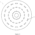
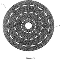
- suction slots (11), represented in figures 5-6 are arranged in rings, concentric and equidistant between them, and the size of each of the slots (11) increases from the centre to the periphery.
- the intermediate part (3) can have three embodiments, as can be seen in figures 7-9 respectively.
- the intermediate part (3) comprises:
Landscapes
- Engineering & Computer Science (AREA)
- Mechanical Engineering (AREA)
- Grinding-Machine Dressing And Accessory Apparatuses (AREA)
- Polishing Bodies And Polishing Tools (AREA)
- Manufacturing Of Magnetic Record Carriers (AREA)
- Finish Polishing, Edge Sharpening, And Grinding By Specific Grinding Devices (AREA)
- Drilling Tools (AREA)
Abstract
Description
- The present invention relates to a backing pad with slots for sanding discs with multiple holes which allows the placement of the disc in the backing pad with a misalignment of the hole with respect to the slot of the backing pad. Wherein it guarantees that the remaining holes of the disc match with the slots that are designed for suction to match, thus facilitating the placement of the disc in the backing pad.
- The backing pad with slots for sanding discs with multiple holes described in the present invention was designed to meet the following principles:
- There are concentric rings and equidistant between them in order to ensure a uniform suction over the whole area of the backing pad;
- In each concentric ring, previously mentioned, slots were built equidistant between them in order to maintain the suction area uniform;
- The width of the slots in each of the concentric rings is designed so that regardless of the misalignment that may occur in the outer holes of the disc with respect to the outer slots of the backing pad it is ensured that the inner holes of the discs still match with the respective slots. Thus reaching the widths of slots shown in the attached drawings, which allows the area of the slots to be optimized and avoiding oversizing thereof and subsequent reduction of the air speeds and flow rates in each slot/hole and always ensuring that the hole match with the slot for more effective removal of dust and particles resulting from sanding.
- The distance from each ring of the backing pad to its centre and between each of the rings is designed so that the holes existing on the traditional discs available on the market could be used with the present backing pad, maintaining all the holes matching or partially matching with the slots of the backing pads.
- The equidistance either of the rings or of the slots between each one respectively, and the width of the slots in each ring allows an easy placement of the disc on the backing pad by simply placing any hole matching with a slot, thus avoiding the search of any specific position to ensure the matching of the disc holes with the backing pad slots. The present system/concept may also be used in sanding backing pad/disc with 75 mm to 225 mm diameter, and the number of concentric rings., the number of slots, the number of holes in the disc and the distance between each one of them can be changed in order to maintain the effectiveness of the suction/removal of the dust resulting from sanding and always respecting the principle defined above concerning the equidistance of both the rings or of the slots between each of them respectively.
- The size of the slots enables the use of discs without holes, thereby giving greater stability to the disc during the sanding process of uneven surfaces.
- In order to optimize the air flows in the inner part of the backing pad various models of the backing pad have been developed and tested, essentially in the construction of channels inside them to optimize the air flows therein. Given the greater difficulty of removing dust on the inner region of the backing pad that is the region of greatest accumulation of dust, the design of the suction channels on the inner side of the backing pad allows greater efficiency in the removal of sanding dust in those regions, most precisely in the smaller concentric ring created in this backing pad. The principle was to place suction channels (inside the backing pad) that match with each concentric ring of slots, wherein each of these suction channels may be connected directly, or not, to the other suction channels. Such suction channels may be built on the inner portion of the foam or on the inner portion of the rigid region of the fastening of the backing pad to the machine.
- With respect to the known multiple holes systems of the prior art, the advantages of the backing pad with slots for sanding discs with multiple holes described in the present invention are as follows:
- There are systems that do not require the alignment of the holes with respect to the backing pad, and most of the holes of the disc with multiple holes do not match with the holes in the backing pad. In these cases, it is also possible to use other set of holes of the discs, but limited to only a few varieties already existing on the market. This applies in the case if you want to keep always all the holes of disc matching with the holes of the backing pad. In the case of the present invention, with the alignment of only one hole with a slot it is ensured the alignment of all other holes with the slots (those that were set to match with the slots). With respect to the remaining set of holes of discs existing on the market, the majority and the most significant can be used with the backing pad with slots, ensuring the matching (total or partial) of the holes with the slots.
- There are multiple holes systems which require the alignment of 1 or more specific holes existing in the disc and in the backing pad, so that the remaining holes of the disc match with all the holes of the backing pad. In the case of the present invention it may be any hole of the disc at any slot of the backing pad, ensuring the matching of the remaining (which was set to match with the slots). The great advantage of the present invention is that is not necessary to rotate the disc and/or the backing pad until finding such specific holes.
- There are multiple holes systems as described in the preceding paragraphs, which in addition to the discs with multiple holes allow the use of other set of holes known on the market, however, in the case of the set of holes of discs with 15 holes, it requires the alignment of 2 or 4 specific holes of the disc, so that the remaining match with the holes of the backing pad.
- The backing pad with slots for sanding discs with multiple holes described in the present invention can be aligned on the backing pad through any of the holes, ensuring the matching of all or part of the remaining slots.
- The description presented below is made with reference to the attached drawings which are presented only by reference, without any limitative character, and wherein:
-
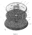
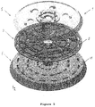
Figures 1-3 are isometric views of the backing pad with slots for sanding discs with multiple holes; -
Figure 4 is a view of the front face of the lower part of the backing pad with slots for sanding discs with multiple holes; -
Figure 5 is a view of the rear face of the lower part of the backing pad with slots for sanding discs with multiple holes; -
Figure 6 is a view of the rear face of the lower part of the backing pad with slots for sanding discs with multiple holes; -
Figures 7-9 are views of the rear face of the intermediate part of the backing pad with slots for sanding discs with multiple holes; -
Figure 10 is a view of the rear face of the upper part of the backing pad with slots for sanding discs with multiple holes; -
Figure 11 is a top view of a sanding disc with multiple holes, with 56H+1 holes; -
Figure 12 is a top view of a sanding disc with multiple holes, with 21F+1 holes; -
Figure 13 is a top view of a sanding disc with 15 holes and the corresponding misalignment with the backing pad with multiple holes; -
Figure 14 is a top view of a sanding disc with multiple holes, with 56+1 holes; -
Figure 15 is a top view of a sanding disc with multiple holes, with 80+1 holes; and -
Figure 16 is a top view of a sanding disc with 15 holes. -
- Backing pad (1)
- Upper part (2)
- Intermediate part (3)
- Lower part (4)
- Slots (5) of the intermediate part
- Channels (6)
- Holes (7) of the upper part
- Central hole (8)
- Grooves (9)
- Upraised walls (10)
- Slots (11) of the lower part
- Holes (12) located on a concentric ring of the intermediate part
- Equidistant holes (13) and located on a concentric ring for fastening the intermediate part to the upper part by means of respective engagement and gluing.
- Backing pad with slots for sanding discs with multiple holes effectively enable an improved removal of sanding material which is expressed by the absence of dust accumulation on the periphery of the discs and of the sanding backing pad when used with the backing pad described in the present invention.
- The present invention relates to a backing pad with slots for sanding discs with multiple holes, which allows the placement of the disc in the backing pad with a misalignment of the hole with respect to the slot of the backing pad of 8mm. Which ensures the matching of the remaining holes of the disc with the respective slots (that have been set for the suction to matching) - thereby facilitating the placement of the disk in the backing pad.
- When using a disc on a backing pad (in the current case with a grip type of fastening system) it is well known that movements occur during the process of sanding due to the rotation of the machine and to the friction that occurs between the disc and the material that is sanded. Such movements cause misalignment in the matching of the holes. The more holes the backing pad/disc have and the smaller it is their diameter more evident is the misalignment, reaching critical cases where the hole of the disc does not match with the hole of the backing pad (during the sanding process) hindering the removal of sanding dust and accumulating excessive of said dust on the backing pad. In the case of the present invention, and if the hole is properly aligned and centred in the respective slot,
Figure 11 , the above mentioned technical issue will not occur because the disc will be able to move rotationally to either side by about 4mm (in the case of the disc with the set of holes 56H + 1) and the matching of the hole with the slot will be maintained,Figure 11 , maintaining an efficient suction and preventing the excessive dust accumulation on the backing pad in the area of the holes. - In the case of a disc with a set of holes 20H+1 the disc will be able to move rotationally to either side by about 2.5 mm,
Figure 12 , and the matching of the hole of the disc with respect to the slot will be maintained, however, if this movement is higher, as the size of the hole is 8 mm the total misalignment will never occur. That is, even when this movement is higher at least a partial matching will be kept which will always ensure the removal of dust,Figure 12 . - To place the disc with multiple holes in the backing pad with slots you just have to align any of the holes of the disc with any of the slots of the backing pad, wherein the remaining holes of the disc will always match with all the slots of the backing pad (which were set for the suction to matching) for the disc with the set of holes 56H+1,
Figure 11 . In the case of the set of holes 20H+1 all the holes of the disc will match with the slots of the backing pad,Figure 12 . - In order for the whole area of the disc to have an uniform suction and without prejudice to the reduction of air speed in each slot, it was decided not to increase the amount of slots, however, holes of the disc were set for not to match with slots, but due to air flows which are caused by closer slots effective suction is ensured by these holes. In the case of discs with the set of holes 20H+1, all the holes of the disc always match with the slots of the backing pad, regardless of the position of the disc with respect to the backing pad,
Figure 12 . - The suction occurring in holes that do not match,
Figure 11 , above described, may not be enough in the case the particles resulting from the sanding are bigger than a certain size, in this case, the backing pad may be designed with 80 slots which match with all the holes of the discs 56H+1 or 80H+1, according toFigures 14-15 . In the case of disc 20H+1, this technical issue will not occur because, regardless of the disc placement, all the holes match always with the slots,Figure 12 . - Given the geometry of the backing pad and the size of the slot with a low flow rate of the suction system it is guaranteed a specific air speed in each slot that allows a good suction effectiveness and the consequent dust removal. In traditional systems, the size of the holes does not guarantee, with a low flow rate of the suction system, an air speed that enables a good suction effectiveness and the consequent dust removal.

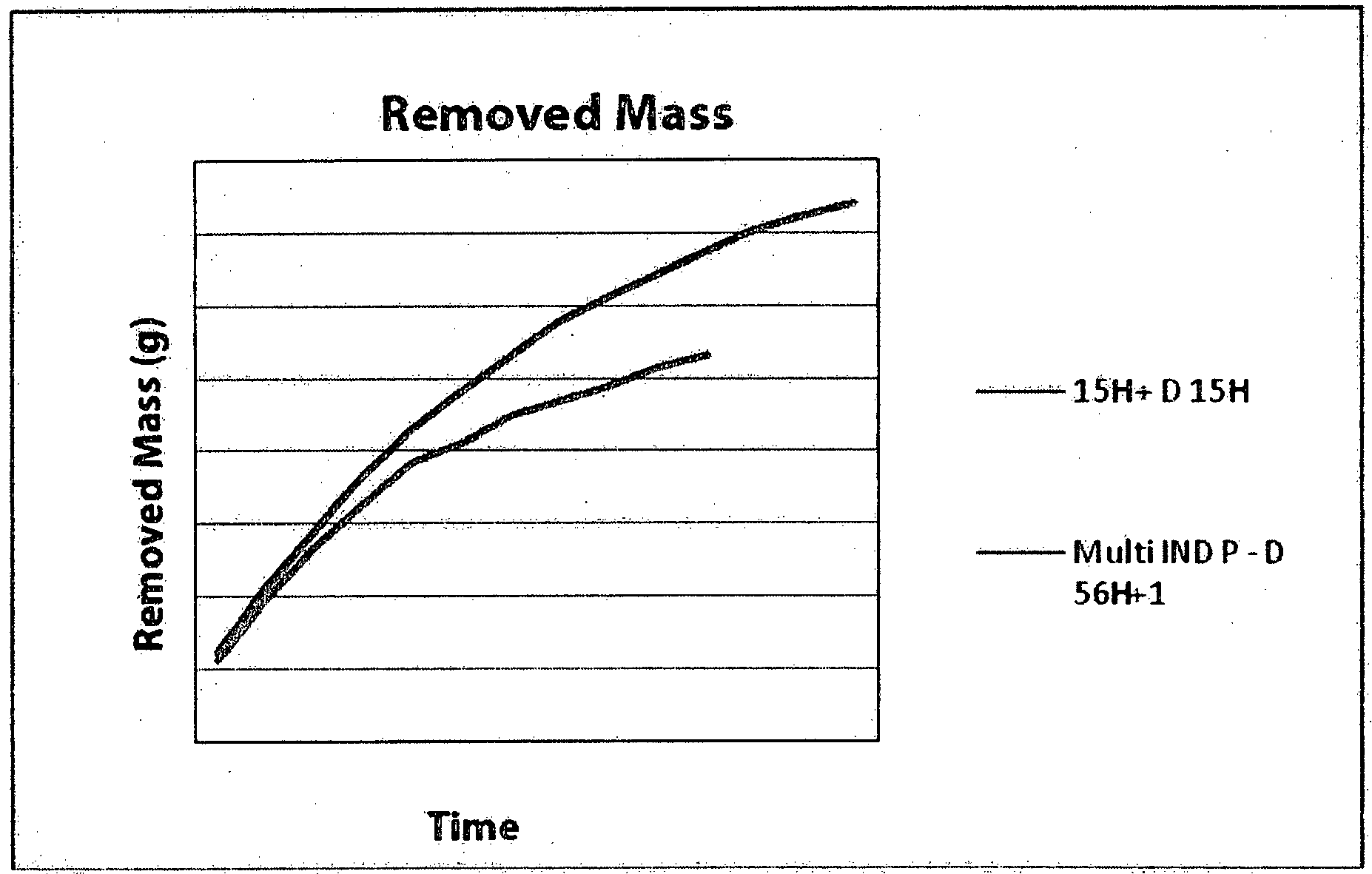
- The analysis of the above graphs shows that in the case of a normal suction flow rate the yield difference between the 15H system and the system of the present invention is smaller.
- In the case of a low suction flow rate the yield difference between the 15H system and the system of the present invention is considerably higher.
- By normal flow rate is meant: the flow rate powered by a vacuum cleaner for sanding systems that are clean - Filters + New dust collection bag.
- By low flow rate is meant: the flow rate powered by a vacuum cleaner for sanding systems with clogged filters and dust collection bag.
- Any backing pad of 15H or more holes existing on the market requires for the alignment of the set of holes of the discs 15H with the backing pad of 15 holes to rotate the disc (or backing pad) so that the 2 (or four holes) aligned along the disc diameter may coincide with the respective holes of the backing pad (with holes of the same geometry). In the case of the placement in the backing pad with slots of a disc with 15 holes we only have to align any of the holes of the disc 15H with any of the slots and all the others will match (total or partial) with the slots of the backing pad,
Figure 16 . - In the case of utilization of backing pads 15H with discs without holes, in the area of the holes of the backing pad the discs without holes are subject to a large area without sustainability. In the case of the backing pad with slot, given the small size of the slots (
width 3 mm), it allows the placement of discs without holes minimizing the most the disc area that is unsustainable on the backing pad. - That is, the traditional backing pads with multiple holes with 15 holes (included) or those of 15 holes or 8
holes 8 or those of 6 holes, when one disc without holes is placed for sanding operations of uneven surfaces (e.g. contoured, protrusions, etc.) the disc can de damaged in the region of the holes of the backing pad, as the diameter of the holes is 8 - 10 mm. In the case of the backing pad of the present invention given the size of each slot and essentially in the innermost concentric rings where the area of each slot is smaller the risk of damaging the sanding disc without holes is substantially avoided (it should be noted that the most central portion of the disc is usually the most requested in the above mentioned sanding operations). - In the case of discs with the set of holes 8H+1, 8H, 6H+1 and 6H the geometry of the slots on the backing pad allows, also requiring the alignment of only any hole of the disc with any of the slots, the instantaneous alignment of the remaining holes of the disc with the slots of the backing pad,
Figure 16 . - By ensuring the matching of one slot (or part of the slot) with any of the holes of the disc (all of the above mentioned set of holes) good suction is guaranteed according to the respective backing pads for the respective set of holes (Backing pad 6H+1 with discs 6H+1 and 6H, Backing pad 8H+1 with discs 8H+1 and 8H, Backing pad 15H with discs 15H). Thus the yield of the discs according to the combination of Backing pad 15 Holes and the backing pad of the present invention with the various set of holes already mentioned, remain very close as it is shown in the chart below.


- IND 15H - 6H+1: Test performed with backing pad of 15 holes and disc with 6 holes plus 1;
- IND 15H - D15H: Test performed with backing pad of 15 holes and disc with 15 holes;
- Multi IND A - 6H+1: Test performed with backing pad Multi-Indasa and disc with 6 holes plus 1;
- Multi IND A - D15H: Test performed with backing pad Multi-Indasa and disc with 15 holes.
- The backing pad described in the present invention allows during the placement of the disc in the backing pad with slots a misalignment of the hole with respect to the slot of the backing pad of about 3mm,
Figure 13 . Wherein it ensures the matching (partial or total) of the remaining holes of the disc with the slots thus making it easier to place the disc. - As can be seen in
figures 1-3 the backing pad (1) with slots for sanding discs with multiple holes, comprising three parts joined together by a fastening system: - the upper part (2), with a frustoconical shape, includes suction holes (7) and a central hole (8);
- the intermediate part (3) comprises suction slots (5), a central hole (8') and in the rear face some suction channels (6) bordered by upraised walls (10);
- the lower part (4), with a frustoconical shape, and in which the intermediate part (3) will engage, comprises slots (5) and a central hole (8''), and some suction slots (11) which are arranged in rings, concentric and equidistant between them, and the size of each of the slots (11) increases from the centre to the periphery.
- In
Figure 6 it can be seen that the rear face of the lower part (4) comprises suction grooves (9), located at concentric and equidistant rings between them, said grooves (9) include the slots (11). - The suction slots (5) of the intermediate part (3) match with the suction slots (11) of the lower part (4).
- In the backing pad with slots for sanding discs with multiple holes the intermediate part (3) comprises various holes (13) equidistant and located according to a concentric ring for fastening the intermediate part to the upper part by means of respective engagement and gluing.
- The shape of the upraised walls (10) delimiting the channels (6) defines the shape of the channels (6).
- The lower part (4) can have two embodiments, as can be seen in
figures 5-6 respectively. - The suction slots (11), represented in
figures 5-6 , are arranged in rings, concentric and equidistant between them, and the size of each of the slots (11) increases from the centre to the periphery. - On the other hand, the intermediate part (3) can have three embodiments, as can be seen in
figures 7-9 respectively. - Thus, in one of the embodiments, as can be seen in
figure 9 the intermediate part (3) comprises: - equidistant holes (12) on the periphery;
- inside the upraised walls (10), bordering the suction channels (6), holes (12) that are located on a concentric ring; and
- Inside the upraised walls (10) bordering the suction channels (6), some holes (14).
- As will be apparent to one skilled in the art, it is possible various minor alterations, which, however, should be included within the scope of the invention.
- The invention should be limited only by the spirit of the following claims.
Claims (6)
- Backing pad (1) with slots for sanding discs with multiple holes, comprising three parts, upper, intermediate and lower, joined together by a fastening system in which the upper part (2), with a frustoconical shape, includes suction holes (7) and a central hole (8), characterized in that- the intermediate part (3) comprises suction slots (5), a central hole (8') and in the rear face some suction channels (6) bordered by upraised walls (10);- the lower part (4), with a frustoconical shape, and in which the intermediate part (3) will engage, comprises slots (5) and a central hole (8''), and some suction slots (11) which are arranged in rings, concentric and equidistant between them, and the size of each of the slots (11) increases from the centre to the periphery.
- Backing pad with slots for sanding discs with multiple holes according to the preceding claim, characterized in that the front face of the lower part (4) comprises suction grooves (9), located at concentric and equidistant rings between them, said grooves (9) include the slots (11).
- Backing pad with slots for sanding discs with multiple holes according to claim 1, characterized in that the suction slots (5) of the intermediate part (3) match with the suction slots (11) of the lower part (4).
- Backing pad with slots for sanding discs with multiple holes according to claim 1, characterized in that the intermediate part (3) comprises:- equidistant holes (112) on the periphery;- inside the upraised walls (110), bordering the suction channels (6), holes (12) that are located on a concentric ring; and- inside the upraised walls (10) bordering the suction channels (6), some holes (14).
- Backing pad with slots for sanding discs with multiple holes according to claim 1, characterized in that the intermediate part (3) further comprises equidistant fastening holes (13) located on a concentric ring.
- Backing pad with slots for sanding discs with multiples holes according to claim 1, characterized in that the shape of the upraised walls (10) bordering the channels (6) defines the shape of the channels (6).
Priority Applications (3)
| Application Number | Priority Date | Filing Date | Title |
|---|---|---|---|
| HRP20171806TT HRP20171806T1 (en) | 2014-02-06 | 2015-01-15 | Backing pad with slots for sanding disks with multiple holes |
| PL15708912T PL3040160T3 (en) | 2014-02-06 | 2015-01-15 | Backing pad with slots for sanding disks with multiple holes |
| RS20171197A RS56644B1 (en) | 2014-02-06 | 2015-01-15 | Backing pad with slots for sanding disks with multiple holes |
Applications Claiming Priority (2)
| Application Number | Priority Date | Filing Date | Title |
|---|---|---|---|
| PT107454A PT107454A (en) | 2014-02-06 | 2014-02-06 | DISH RATING FOR MULTIPURPOSE SANDING DISKS |
| PCT/PT2015/000003 WO2015119521A1 (en) | 2014-02-06 | 2015-01-15 | Backing pad with slots for sanding disks with multiple holes |
Publications (2)
| Publication Number | Publication Date |
|---|---|
| EP3040160A1 true EP3040160A1 (en) | 2016-07-06 |
| EP3040160B1 EP3040160B1 (en) | 2017-08-23 |
Family
ID=52633565
Family Applications (1)
| Application Number | Title | Priority Date | Filing Date |
|---|---|---|---|
| EP15708912.9A Active EP3040160B1 (en) | 2014-02-06 | 2015-01-15 | Backing pad with slots for sanding disks with multiple holes |
Country Status (21)
| Country | Link |
|---|---|
| US (1) | US9975219B2 (en) |
| EP (1) | EP3040160B1 (en) |
| JP (1) | JP6437013B2 (en) |
| KR (1) | KR102276033B1 (en) |
| CN (1) | CN105517760B (en) |
| AU (1) | AU2015214674B2 (en) |
| CA (1) | CA2920502C (en) |
| DK (1) | DK3040160T3 (en) |
| ES (1) | ES2648671T3 (en) |
| HR (1) | HRP20171806T1 (en) |
| HU (1) | HUE037182T2 (en) |
| LT (1) | LT3040160T (en) |
| MX (1) | MX377343B (en) |
| NO (1) | NO3040160T3 (en) |
| PL (1) | PL3040160T3 (en) |
| PT (2) | PT107454A (en) |
| RS (1) | RS56644B1 (en) |
| RU (1) | RU2652305C2 (en) |
| SA (1) | SA516370632B1 (en) |
| WO (1) | WO2015119521A1 (en) |
| ZA (1) | ZA201600933B (en) |
Families Citing this family (11)
| Publication number | Priority date | Publication date | Assignee | Title |
|---|---|---|---|---|
| EP3580011B1 (en) * | 2017-02-13 | 2025-05-21 | Mirka Ltd. | Conduit arrangements in a backing pad |
| IT201700087962A1 (en) * | 2017-07-31 | 2019-01-31 | Abrex System S R L | SUPPORT DEVICE FOR ABRASIVE ELEMENTS |
| CN109129223B (en) * | 2018-09-27 | 2024-12-24 | 东莞金太阳研磨股份有限公司 | Improved disc sandpaper and grinding equipment with the disc sandpaper |
| DE102018131591A1 (en) * | 2018-12-10 | 2020-06-10 | Dongguan Golden Sun Abrasives Co., Ltd. | Disc sanding paper and grinder |
| USD925318S1 (en) * | 2019-02-28 | 2021-07-20 | Guido Valentini | Delta shaped backing pad with dove-tail |
| EP3812089A1 (en) | 2019-10-23 | 2021-04-28 | Black & Decker Inc. | Pole sander |
| EP4178764A1 (en) * | 2020-07-13 | 2023-05-17 | 3M Innovative Properties Company | Repositionable abrasive disc mounting assembly and method of using the same |
| US11867224B2 (en) | 2021-01-27 | 2024-01-09 | Black & Decker Inc. | Locking mechanism for two telescoping poles of a power tool |
| DE102021209532A1 (en) | 2021-08-31 | 2023-03-02 | Tts Microcell Gmbh | Sanding pad for a sander and sanding system |
| USD1021595S1 (en) * | 2022-08-31 | 2024-04-09 | Smart, Llc | Polishing pad |
| DE102024206337A1 (en) * | 2024-07-05 | 2026-01-08 | Robert Bosch Gesellschaft mit beschränkter Haftung | Grinding and/or polishing pad device, grinding and/or polishing machine and method for manufacturing a grinding and/or polishing pad device |
Family Cites Families (22)
| Publication number | Priority date | Publication date | Assignee | Title |
|---|---|---|---|---|
| CA1053005A (en) * | 1976-09-24 | 1979-04-24 | Miksa Marton | Pad assembly for vacuum rotary sander |
| JPS5542703A (en) * | 1978-09-11 | 1980-03-26 | Marton Miksa | Pad assembled body of vacuum rotary sander |
| US4287685A (en) * | 1978-12-08 | 1981-09-08 | Miksa Marton | Pad assembly for vacuum rotary sander |
| JPS6343022Y2 (en) * | 1980-07-19 | 1988-11-10 | ||
| IT1298432B1 (en) * | 1997-02-28 | 2000-01-10 | Bosch Gmbh Robert | SANDING PLATE FOR A PORTABLE POWER TOOL WITH DUST EXTRACTION |
| SE511708C2 (en) * | 1998-06-23 | 1999-11-08 | Ekamant Ab | Compressed air powered hand grinding tool with an ejector unit for suction of a grinding sheet and support plate for use therein |
| JP3895256B2 (en) * | 2002-10-11 | 2007-03-22 | Ykk株式会社 | Polishing substrate for portable polishing machine |
| ITMI20031971A1 (en) * | 2003-10-13 | 2005-04-14 | Luca Lavazza | COMBINED SYSTEM OF ABRASIVE DISC AND ITS SUPPORT SUPPORT OR ROTARY SIDING PLATE FOR DIRECT RADIAL SUCTION OF THE DUST PRODUCED |
| DE10357143A1 (en) * | 2003-12-06 | 2005-06-30 | Robert Bosch Gmbh | Grinding assembly for an electric hand tool machine |
| JP2005186165A (en) * | 2003-12-24 | 2005-07-14 | Disco Abrasive Syst Ltd | Dry polishing machine |
| DE102004018727A1 (en) * | 2004-04-17 | 2005-11-10 | Jöst, Peter | Sanding disc with self-suction device and method for removing Schleifpatikeln |
| RU2392105C2 (en) * | 2005-09-16 | 2010-06-20 | Паскуале КАТАЛФАМО | Abrasive head |
| JP5095180B2 (en) * | 2006-09-15 | 2012-12-12 | スリーエム イノベイティブ プロパティズ カンパニー | Dust absorption sander and dust absorption polishing device |
| DE502007004094D1 (en) * | 2007-12-11 | 2010-07-22 | Festool Gmbh | Sanding pad and sanding sheet |
| EP2231364A4 (en) * | 2007-12-31 | 2013-11-06 | Saint Gobain Abrasives Inc | Interface pad for use between an abrasive article and a support tool |
| DE202008001473U1 (en) * | 2008-02-01 | 2008-06-26 | Storm Pneumtic Tool Co., Ltd., Dali City | grinding wheel |
| ITMI20080222U1 (en) * | 2008-07-15 | 2010-01-16 | Valentini Guido | "CUP FOR WORKING SURFACES WITH CURVED SUCTION CHANNELS" |
| DE102009013370A1 (en) * | 2009-03-09 | 2010-09-16 | C. & E. Fein Gmbh | Plate-shaped oscillating tool for e.g. sawing joint material, has working surface for grinding or polishing purpose, where quotient of working surface of tool and rated power of drive motor is of specific value |
| EP2364633A1 (en) | 2010-03-09 | 2011-09-14 | Koninklijke Philips Electronics N.V. | A vacuum cleaner |
| WO2012020275A1 (en) * | 2010-08-10 | 2012-02-16 | Miksa Marton | Sanding apparatus |
| DE202010018005U1 (en) * | 2010-08-31 | 2013-07-08 | Jöst Gmbh | Sanding pad unit for a rotary sanding machine |
| JP5765017B2 (en) | 2011-03-31 | 2015-08-19 | 日立工機株式会社 | Dust collecting cover and disc grinder with dust collecting cover |
-
2014
- 2014-02-06 PT PT107454A patent/PT107454A/en unknown
-
2015
- 2015-01-15 WO PCT/PT2015/000003 patent/WO2015119521A1/en not_active Ceased
- 2015-01-15 HR HRP20171806TT patent/HRP20171806T1/en unknown
- 2015-01-15 JP JP2016568785A patent/JP6437013B2/en active Active
- 2015-01-15 HU HUE15708912A patent/HUE037182T2/en unknown
- 2015-01-15 EP EP15708912.9A patent/EP3040160B1/en active Active
- 2015-01-15 PL PL15708912T patent/PL3040160T3/en unknown
- 2015-01-15 CA CA2920502A patent/CA2920502C/en active Active
- 2015-01-15 KR KR1020167005950A patent/KR102276033B1/en active Active
- 2015-01-15 CN CN201580001785.7A patent/CN105517760B/en active Active
- 2015-01-15 ES ES15708912.9T patent/ES2648671T3/en active Active
- 2015-01-15 RU RU2016105531A patent/RU2652305C2/en active
- 2015-01-15 MX MX2016006526A patent/MX377343B/en active IP Right Grant
- 2015-01-15 AU AU2015214674A patent/AU2015214674B2/en active Active
- 2015-01-15 DK DK15708912.9T patent/DK3040160T3/en active
- 2015-01-15 US US14/912,093 patent/US9975219B2/en active Active
- 2015-01-15 RS RS20171197A patent/RS56644B1/en unknown
- 2015-01-15 LT LTEP15708912.9T patent/LT3040160T/en unknown
- 2015-01-15 NO NO15708912A patent/NO3040160T3/no unknown
- 2015-01-15 PT PT157089129T patent/PT3040160T/en unknown
-
2016
- 2016-02-10 ZA ZA2016/00933A patent/ZA201600933B/en unknown
- 2016-02-27 SA SA516370632A patent/SA516370632B1/en unknown
Non-Patent Citations (2)
| Title |
|---|
| None * |
| See also references of WO2015119521A1 * |
Also Published As
| Publication number | Publication date |
|---|---|
| PL3040160T3 (en) | 2018-01-31 |
| HUE037182T2 (en) | 2018-08-28 |
| RU2016105531A (en) | 2018-03-15 |
| US20160354900A1 (en) | 2016-12-08 |
| MX2016006526A (en) | 2016-08-19 |
| JP2017507801A (en) | 2017-03-23 |
| KR102276033B1 (en) | 2021-07-13 |
| SA516370632B1 (en) | 2020-05-11 |
| CN105517760B (en) | 2017-12-22 |
| HK1219928A1 (en) | 2017-04-21 |
| CA2920502A1 (en) | 2015-08-13 |
| LT3040160T (en) | 2017-12-11 |
| US9975219B2 (en) | 2018-05-22 |
| WO2015119521A1 (en) | 2015-08-13 |
| ZA201600933B (en) | 2018-11-28 |
| MX377343B (en) | 2025-03-07 |
| EP3040160B1 (en) | 2017-08-23 |
| DK3040160T3 (en) | 2017-12-04 |
| PT107454A (en) | 2015-08-06 |
| CA2920502C (en) | 2022-03-08 |
| NO3040160T3 (en) | 2018-01-20 |
| ES2648671T3 (en) | 2018-01-05 |
| RS56644B1 (en) | 2018-03-30 |
| PT3040160T (en) | 2017-11-30 |
| CN105517760A (en) | 2016-04-20 |
| JP6437013B2 (en) | 2018-12-12 |
| RU2016105531A3 (en) | 2018-03-21 |
| AU2015214674A1 (en) | 2016-05-05 |
| KR20160119048A (en) | 2016-10-12 |
| AU2015214674B2 (en) | 2018-11-01 |
| HRP20171806T1 (en) | 2017-12-29 |
| RU2652305C2 (en) | 2018-04-25 |
Similar Documents
| Publication | Publication Date | Title |
|---|---|---|
| EP3040160B1 (en) | Backing pad with slots for sanding disks with multiple holes | |
| EP3616584B1 (en) | Vacuum cleaner | |
| JP6212649B2 (en) | Nozzle for vacuum cleaner | |
| EP1524077A1 (en) | Combined system of abrasive disc and related support or rotary backup pad for direct radial suction of the dust | |
| US8684792B2 (en) | Sanding system with vacuum | |
| US10369680B2 (en) | Abrasive disc with universal hole pattern | |
| EP0538331B1 (en) | Abrasive throwing wheel assemblies | |
| EP3437800B1 (en) | Supporting device for abrasive elements | |
| DE102010028123A1 (en) | Sharpening plate device for hand-guided grinder, has sand paper arranged on bottom side of sharpening plate, and hook-and-loop fastener whose sections are extended to sharpening plate over partial flange of bottom side of sharpening plate | |
| JP6389620B2 (en) | Polishing pad | |
| KR100628387B1 (en) | Suction brush of vacuum cleaner | |
| HK1219928B (en) | Backing pad with slots for sanding disks with multiple holes | |
| BR102016003549B1 (en) | Plate with slots for multi-hole sanding discs | |
| CN108581861B (en) | A fixed plate for vertical impeller | |
| US2332676A (en) | Grinding head | |
| CN107061546B (en) | A kind of centrifugal clutch | |
| KR200433114Y1 (en) | Grinding Disc Structure | |
| CN213155683U (en) | a cleaning robot | |
| EP2829359A3 (en) | Improved abrasive device | |
| EP3275594A1 (en) | Backing plate unit | |
| CN113243827A (en) | Inhale and drag integrative cleaning machines people |
Legal Events
| Date | Code | Title | Description |
|---|---|---|---|
| PUAI | Public reference made under article 153(3) epc to a published international application that has entered the european phase |
Free format text: ORIGINAL CODE: 0009012 |
|
| 17P | Request for examination filed |
Effective date: 20160223 |
|
| AK | Designated contracting states |
Kind code of ref document: A1 Designated state(s): AL AT BE BG CH CY CZ DE DK EE ES FI FR GB GR HR HU IE IS IT LI LT LU LV MC MK MT NL NO PL PT RO RS SE SI SK SM TR |
|
| AX | Request for extension of the european patent |
Extension state: BA ME |
|
| DAX | Request for extension of the european patent (deleted) | ||
| GRAP | Despatch of communication of intention to grant a patent |
Free format text: ORIGINAL CODE: EPIDOSNIGR1 |
|
| INTG | Intention to grant announced |
Effective date: 20170522 |
|
| GRAS | Grant fee paid |
Free format text: ORIGINAL CODE: EPIDOSNIGR3 |
|
| GRAA | (expected) grant |
Free format text: ORIGINAL CODE: 0009210 |
|
| AK | Designated contracting states |
Kind code of ref document: B1 Designated state(s): AL AT BE BG CH CY CZ DE DK EE ES FI FR GB GR HR HU IE IS IT LI LT LU LV MC MK MT NL NO PL PT RO RS SE SI SK SM TR |
|
| REG | Reference to a national code |
Ref country code: GB Ref legal event code: FG4D |
|
| REG | Reference to a national code |
Ref country code: CH Ref legal event code: EP |
|
| REG | Reference to a national code |
Ref country code: AT Ref legal event code: REF Ref document number: 920824 Country of ref document: AT Kind code of ref document: T Effective date: 20170915 |
|
| REG | Reference to a national code |
Ref country code: IE Ref legal event code: FG4D |
|
| REG | Reference to a national code |
Ref country code: DE Ref legal event code: R096 Ref document number: 602015004324 Country of ref document: DE |
|
| REG | Reference to a national code |
Ref country code: HR Ref legal event code: TUEP Ref document number: P20171806 Country of ref document: HR Ref country code: RO Ref legal event code: EPE |
|
| REG | Reference to a national code |
Ref country code: PT Ref legal event code: SC4A Ref document number: 3040160 Country of ref document: PT Date of ref document: 20171130 Kind code of ref document: T Free format text: AVAILABILITY OF NATIONAL TRANSLATION Effective date: 20171123 |
|
| REG | Reference to a national code |
Ref country code: DK Ref legal event code: T3 Effective date: 20171127 |
|
| REG | Reference to a national code |
Ref country code: SE Ref legal event code: TRGR |
|
| REG | Reference to a national code |
Ref country code: NL Ref legal event code: FP |
|
| REG | Reference to a national code |
Ref country code: FR Ref legal event code: PLFP Year of fee payment: 4 |
|
| REG | Reference to a national code |
Ref country code: HR Ref legal event code: T1PR Ref document number: P20171806 Country of ref document: HR |
|
| REG | Reference to a national code |
Ref country code: ES Ref legal event code: FG2A Ref document number: 2648671 Country of ref document: ES Kind code of ref document: T3 Effective date: 20180105 |
|
| REG | Reference to a national code |
Ref country code: EE Ref legal event code: FG4A Ref document number: E014586 Country of ref document: EE Effective date: 20171120 |
|
| REG | Reference to a national code |
Ref country code: CH Ref legal event code: NV Representative=s name: ISLER AND PEDRAZZINI AG, CH |
|
| REG | Reference to a national code |
Ref country code: NO Ref legal event code: T2 Effective date: 20170823 |
|
| PG25 | Lapsed in a contracting state [announced via postgrant information from national office to epo] |
Ref country code: BG Free format text: LAPSE BECAUSE OF FAILURE TO SUBMIT A TRANSLATION OF THE DESCRIPTION OR TO PAY THE FEE WITHIN THE PRESCRIBED TIME-LIMIT Effective date: 20171123 Ref country code: IS Free format text: LAPSE BECAUSE OF FAILURE TO SUBMIT A TRANSLATION OF THE DESCRIPTION OR TO PAY THE FEE WITHIN THE PRESCRIBED TIME-LIMIT Effective date: 20171223 |
|
| REG | Reference to a national code |
Ref country code: GR Ref legal event code: EP Ref document number: 20170403206 Country of ref document: GR Effective date: 20180420 |
|
| REG | Reference to a national code |
Ref country code: DE Ref legal event code: R097 Ref document number: 602015004324 Country of ref document: DE |
|
| PG25 | Lapsed in a contracting state [announced via postgrant information from national office to epo] |
Ref country code: SM Free format text: LAPSE BECAUSE OF FAILURE TO SUBMIT A TRANSLATION OF THE DESCRIPTION OR TO PAY THE FEE WITHIN THE PRESCRIBED TIME-LIMIT Effective date: 20170823 Ref country code: SK Free format text: LAPSE BECAUSE OF FAILURE TO SUBMIT A TRANSLATION OF THE DESCRIPTION OR TO PAY THE FEE WITHIN THE PRESCRIBED TIME-LIMIT Effective date: 20170823 |
|
| PLBE | No opposition filed within time limit |
Free format text: ORIGINAL CODE: 0009261 |
|
| STAA | Information on the status of an ep patent application or granted ep patent |
Free format text: STATUS: NO OPPOSITION FILED WITHIN TIME LIMIT |
|
| 26N | No opposition filed |
Effective date: 20180524 |
|
| REG | Reference to a national code |
Ref country code: HU Ref legal event code: AG4A Ref document number: E037182 Country of ref document: HU |
|
| PG25 | Lapsed in a contracting state [announced via postgrant information from national office to epo] |
Ref country code: SI Free format text: LAPSE BECAUSE OF FAILURE TO SUBMIT A TRANSLATION OF THE DESCRIPTION OR TO PAY THE FEE WITHIN THE PRESCRIBED TIME-LIMIT Effective date: 20170823 |
|
| REG | Reference to a national code |
Ref country code: HR Ref legal event code: ODRP Ref document number: P20171806 Country of ref document: HR Payment date: 20190111 Year of fee payment: 5 |
|
| REG | Reference to a national code |
Ref country code: AT Ref legal event code: UEP Ref document number: 920824 Country of ref document: AT Kind code of ref document: T Effective date: 20170823 |
|
| PG25 | Lapsed in a contracting state [announced via postgrant information from national office to epo] |
Ref country code: MC Free format text: LAPSE BECAUSE OF FAILURE TO SUBMIT A TRANSLATION OF THE DESCRIPTION OR TO PAY THE FEE WITHIN THE PRESCRIBED TIME-LIMIT Effective date: 20170823 |
|
| REG | Reference to a national code |
Ref country code: HR Ref legal event code: ODRP Ref document number: P20171806 Country of ref document: HR Payment date: 20191213 Year of fee payment: 6 |
|
| PG25 | Lapsed in a contracting state [announced via postgrant information from national office to epo] |
Ref country code: MT Free format text: LAPSE BECAUSE OF NON-PAYMENT OF DUE FEES Effective date: 20180115 |
|
| PG25 | Lapsed in a contracting state [announced via postgrant information from national office to epo] |
Ref country code: MK Free format text: LAPSE BECAUSE OF NON-PAYMENT OF DUE FEES Effective date: 20170823 Ref country code: CY Free format text: LAPSE BECAUSE OF FAILURE TO SUBMIT A TRANSLATION OF THE DESCRIPTION OR TO PAY THE FEE WITHIN THE PRESCRIBED TIME-LIMIT Effective date: 20170823 |
|
| PG25 | Lapsed in a contracting state [announced via postgrant information from national office to epo] |
Ref country code: AL Free format text: LAPSE BECAUSE OF FAILURE TO SUBMIT A TRANSLATION OF THE DESCRIPTION OR TO PAY THE FEE WITHIN THE PRESCRIBED TIME-LIMIT Effective date: 20170823 |
|
| REG | Reference to a national code |
Ref country code: HR Ref legal event code: ODRP Ref document number: P20171806 Country of ref document: HR Payment date: 20210107 Year of fee payment: 7 |
|
| PGFP | Annual fee paid to national office [announced via postgrant information from national office to epo] |
Ref country code: PT Payment date: 20210723 Year of fee payment: 8 |
|
| REG | Reference to a national code |
Ref country code: HR Ref legal event code: ODRP Ref document number: P20171806 Country of ref document: HR Payment date: 20211228 Year of fee payment: 8 |
|
| REG | Reference to a national code |
Ref country code: HR Ref legal event code: ODRP Ref document number: P20171806 Country of ref document: HR Payment date: 20230104 Year of fee payment: 9 |
|
| P01 | Opt-out of the competence of the unified patent court (upc) registered |
Effective date: 20230523 |
|
| REG | Reference to a national code |
Ref country code: HR Ref legal event code: ODRP Ref document number: P20171806 Country of ref document: HR Payment date: 20240105 Year of fee payment: 10 |
|
| REG | Reference to a national code |
Ref country code: HR Ref legal event code: ODRP Ref document number: P20171806 Country of ref document: HR Payment date: 20250110 Year of fee payment: 11 |
|
| PG25 | Lapsed in a contracting state [announced via postgrant information from national office to epo] |
Ref country code: PT Free format text: LAPSE BECAUSE OF NON-PAYMENT OF DUE FEES Effective date: 20230115 |
|
| PGFP | Annual fee paid to national office [announced via postgrant information from national office to epo] |
Ref country code: LT Payment date: 20251218 Year of fee payment: 12 Ref country code: GB Payment date: 20251218 Year of fee payment: 12 |
|
| PGFP | Annual fee paid to national office [announced via postgrant information from national office to epo] |
Ref country code: FI Payment date: 20251230 Year of fee payment: 12 |
|
| PGFP | Annual fee paid to national office [announced via postgrant information from national office to epo] |
Ref country code: HR Payment date: 20251223 Year of fee payment: 12 Ref country code: NL Payment date: 20251225 Year of fee payment: 12 Ref country code: FR Payment date: 20251222 Year of fee payment: 12 |
|
| PGFP | Annual fee paid to national office [announced via postgrant information from national office to epo] |
Ref country code: GR Payment date: 20251230 Year of fee payment: 12 |
|
| REG | Reference to a national code |
Ref country code: HR Ref legal event code: ODRP Ref document number: P20171806 Country of ref document: HR Payment date: 20251223 Year of fee payment: 12 |
|
| PGFP | Annual fee paid to national office [announced via postgrant information from national office to epo] |
Ref country code: IE Payment date: 20251223 Year of fee payment: 12 |
|
| PGFP | Annual fee paid to national office [announced via postgrant information from national office to epo] |
Ref country code: LV Payment date: 20251219 Year of fee payment: 12 |
|
| PGFP | Annual fee paid to national office [announced via postgrant information from national office to epo] |
Ref country code: PL Payment date: 20251230 Year of fee payment: 12 |
|
| PGFP | Annual fee paid to national office [announced via postgrant information from national office to epo] |
Ref country code: EE Payment date: 20251229 Year of fee payment: 12 |
|
| PGFP | Annual fee paid to national office [announced via postgrant information from national office to epo] |
Ref country code: RS Payment date: 20251231 Year of fee payment: 12 |
|
| REG | Reference to a national code |
Ref country code: CH Ref legal event code: U11 Free format text: ST27 STATUS EVENT CODE: U-0-0-U10-U11 (AS PROVIDED BY THE NATIONAL OFFICE) Effective date: 20260201 |
|
| PGFP | Annual fee paid to national office [announced via postgrant information from national office to epo] |
Ref country code: LU Payment date: 20260116 Year of fee payment: 12 |
|
| PGFP | Annual fee paid to national office [announced via postgrant information from national office to epo] |
Ref country code: HU Payment date: 20260122 Year of fee payment: 12 |
|
| PGFP | Annual fee paid to national office [announced via postgrant information from national office to epo] |
Ref country code: SE Payment date: 20251230 Year of fee payment: 12 |
|
| PGFP | Annual fee paid to national office [announced via postgrant information from national office to epo] |
Ref country code: ES Payment date: 20260212 Year of fee payment: 12 |
|
| PGFP | Annual fee paid to national office [announced via postgrant information from national office to epo] |
Ref country code: DE Payment date: 20251216 Year of fee payment: 12 Ref country code: NO Payment date: 20260109 Year of fee payment: 12 Ref country code: DK Payment date: 20260113 Year of fee payment: 12 |
|
| PGFP | Annual fee paid to national office [announced via postgrant information from national office to epo] |
Ref country code: AT Payment date: 20251230 Year of fee payment: 12 |
|
| PGFP | Annual fee paid to national office [announced via postgrant information from national office to epo] |
Ref country code: RO Payment date: 20260112 Year of fee payment: 12 Ref country code: BE Payment date: 20260106 Year of fee payment: 12 Ref country code: IT Payment date: 20251230 Year of fee payment: 12 |
|
| PGFP | Annual fee paid to national office [announced via postgrant information from national office to epo] |
Ref country code: TR Payment date: 20260113 Year of fee payment: 12 |
|
| PGFP | Annual fee paid to national office [announced via postgrant information from national office to epo] |
Ref country code: CH Payment date: 20260201 Year of fee payment: 12 Ref country code: CZ Payment date: 20260109 Year of fee payment: 12 |