EP3038431B1 - Circuit for driving cooker, system for driving cooker, cooker, and method for driving cooker - Google Patents
Circuit for driving cooker, system for driving cooker, cooker, and method for driving cooker Download PDFInfo
- Publication number
- EP3038431B1 EP3038431B1 EP15202268.7A EP15202268A EP3038431B1 EP 3038431 B1 EP3038431 B1 EP 3038431B1 EP 15202268 A EP15202268 A EP 15202268A EP 3038431 B1 EP3038431 B1 EP 3038431B1
- Authority
- EP
- European Patent Office
- Prior art keywords
- unit
- cooker
- driving
- control unit
- sensing
- Prior art date
- Legal status (The legal status is an assumption and is not a legal conclusion. Google has not performed a legal analysis and makes no representation as to the accuracy of the status listed.)
- Active
Links
- 238000000034 method Methods 0.000 title claims description 44
- 238000010411 cooking Methods 0.000 claims description 89
- 230000001276 controlling effect Effects 0.000 description 29
- 238000010438 heat treatment Methods 0.000 description 5
- 230000006698 induction Effects 0.000 description 4
- 238000009413 insulation Methods 0.000 description 4
- 230000005611 electricity Effects 0.000 description 3
- 238000012544 monitoring process Methods 0.000 description 3
- 238000013459 approach Methods 0.000 description 2
- 238000012545 processing Methods 0.000 description 2
- 238000001816 cooling Methods 0.000 description 1
- 230000000593 degrading effect Effects 0.000 description 1
- 230000001419 dependent effect Effects 0.000 description 1
- 230000005672 electromagnetic field Effects 0.000 description 1
- 238000011156 evaluation Methods 0.000 description 1
- 238000004519 manufacturing process Methods 0.000 description 1
- 238000012986 modification Methods 0.000 description 1
- 230000004048 modification Effects 0.000 description 1
- 230000001105 regulatory effect Effects 0.000 description 1
- 230000005236 sound signal Effects 0.000 description 1
- 230000001960 triggered effect Effects 0.000 description 1
- XLYOFNOQVPJJNP-UHFFFAOYSA-N water Substances O XLYOFNOQVPJJNP-UHFFFAOYSA-N 0.000 description 1
Images


Classifications
-
- F—MECHANICAL ENGINEERING; LIGHTING; HEATING; WEAPONS; BLASTING
- F24—HEATING; RANGES; VENTILATING
- F24C—DOMESTIC STOVES OR RANGES ; DETAILS OF DOMESTIC STOVES OR RANGES, OF GENERAL APPLICATION
- F24C7/00—Stoves or ranges heated by electric energy
- F24C7/08—Arrangement or mounting of control or safety devices
-
- A—HUMAN NECESSITIES
- A47—FURNITURE; DOMESTIC ARTICLES OR APPLIANCES; COFFEE MILLS; SPICE MILLS; SUCTION CLEANERS IN GENERAL
- A47J—KITCHEN EQUIPMENT; COFFEE MILLS; SPICE MILLS; APPARATUS FOR MAKING BEVERAGES
- A47J36/00—Parts, details or accessories of cooking-vessels
-
- F—MECHANICAL ENGINEERING; LIGHTING; HEATING; WEAPONS; BLASTING
- F24—HEATING; RANGES; VENTILATING
- F24C—DOMESTIC STOVES OR RANGES ; DETAILS OF DOMESTIC STOVES OR RANGES, OF GENERAL APPLICATION
- F24C7/00—Stoves or ranges heated by electric energy
- F24C7/08—Arrangement or mounting of control or safety devices
- F24C7/087—Arrangement or mounting of control or safety devices of electric circuits regulating heat
-
- F—MECHANICAL ENGINEERING; LIGHTING; HEATING; WEAPONS; BLASTING
- F24—HEATING; RANGES; VENTILATING
- F24C—DOMESTIC STOVES OR RANGES ; DETAILS OF DOMESTIC STOVES OR RANGES, OF GENERAL APPLICATION
- F24C7/00—Stoves or ranges heated by electric energy
- F24C7/08—Arrangement or mounting of control or safety devices
- F24C7/081—Arrangement or mounting of control or safety devices on stoves
-
- F—MECHANICAL ENGINEERING; LIGHTING; HEATING; WEAPONS; BLASTING
- F24—HEATING; RANGES; VENTILATING
- F24C—DOMESTIC STOVES OR RANGES ; DETAILS OF DOMESTIC STOVES OR RANGES, OF GENERAL APPLICATION
- F24C7/00—Stoves or ranges heated by electric energy
- F24C7/08—Arrangement or mounting of control or safety devices
- F24C7/082—Arrangement or mounting of control or safety devices on ranges, e.g. control panels, illumination
-
- H—ELECTRICITY
- H05—ELECTRIC TECHNIQUES NOT OTHERWISE PROVIDED FOR
- H05B—ELECTRIC HEATING; ELECTRIC LIGHT SOURCES NOT OTHERWISE PROVIDED FOR; CIRCUIT ARRANGEMENTS FOR ELECTRIC LIGHT SOURCES, IN GENERAL
- H05B1/00—Details of electric heating devices
- H05B1/02—Automatic switching arrangements specially adapted to apparatus ; Control of heating devices
- H05B1/0227—Applications
- H05B1/0252—Domestic applications
- H05B1/0258—For cooking
-
- H—ELECTRICITY
- H05—ELECTRIC TECHNIQUES NOT OTHERWISE PROVIDED FOR
- H05B—ELECTRIC HEATING; ELECTRIC LIGHT SOURCES NOT OTHERWISE PROVIDED FOR; CIRCUIT ARRANGEMENTS FOR ELECTRIC LIGHT SOURCES, IN GENERAL
- H05B6/00—Heating by electric, magnetic or electromagnetic fields
- H05B6/02—Induction heating
- H05B6/06—Control, e.g. of temperature, of power
- H05B6/062—Control, e.g. of temperature, of power for cooking plates or the like
-
- H—ELECTRICITY
- H05—ELECTRIC TECHNIQUES NOT OTHERWISE PROVIDED FOR
- H05B—ELECTRIC HEATING; ELECTRIC LIGHT SOURCES NOT OTHERWISE PROVIDED FOR; CIRCUIT ARRANGEMENTS FOR ELECTRIC LIGHT SOURCES, IN GENERAL
- H05B6/00—Heating by electric, magnetic or electromagnetic fields
- H05B6/64—Heating using microwaves
- H05B6/6435—Aspects relating to the user interface of the microwave heating apparatus
Definitions
- the present disclosure relates to a circuit for driving a cooker, a system for driving a cooker, a cooker, and a method for driving a cooker, and particularly, to a system for driving a cooker by supplying power according to a result of sensing a movement of a user, a cooker, and a method for driving a cooker.
- a cooker is one of home appliances for cooking food within a container by heating the container using a heat source.
- Cookers may be classified according hot sources.
- cookers include a gas range and a gas oven using a gas, and a microwave oven, an electric oven, and an induction heating cooker using electric power.
- the microwave oven or the electric oven are cookers cooking food using microwaves, in which a microwave generated by a magnetron to which a high voltage is applied is irradiated to a food item within a cooking chamber through a wave guide to vibrate water molecules contained in the food item to generate heat energy , thus cooling the food item.
- Cookers are used in most houses such that a power plug connected to a product is connected to an external alternating current (AC) power source, and in this state, a start switch, or the like, is selectively used, and after the cooker is used, the power plug continues to be put in an electrical outlet.
- AC alternating current
- a related art uses a mechanical switch.
- the mechanical switch since the mechanical switch is used, there is a limitation in that the mechanical switch is operated manually, and in order to cut off standby power and supply power, a user should turned on and turned off the switch each time, degrading user convenience.
- US 2005/0109333 A1 discloses a safety device for regulating electrical power to a cooking appliance, comprising a control module having a power routing means, a power supply means, a load current sensing means for detecting a load current to the cooking appliance and a power relay means for controlling the electrical current to the cooking appliance, and a sensor module located adjacent to the cooking appliance for observation by an appliance operator and connected to the control module.
- the sensor module governs the production of the electrical current to the cooking appliance, and has a monitoring means, a distance sensing means, a timer means for showing elapsed cooking time, and a light emitting means.
- the monitoring means is responsive to outputs of the distance sensing means and includes a timer assembly programmed to a predetermined period of time for responding to the distance sensing means detecting the presence of the appliance operator.
- WO 2011/133119 A2 discloses a zero power standby system for controlling electric appliances that is able to wait for switch on instructions without any power consumption. This is done by a remote controller transmitting power in form of either electromagnetic field, light, or audio signal to a power receiving section of a control signal receiving device. The power receiving section will then use the received power to force a multi-switch section to connect between a power supply and a control signal receiving section and a control signal processing section and put the appliance into its usual running mode. When a user desires to turn off the electric appliance, the system stop supplying power to the control signal receiving section and the control signal processing section by turning off multi-switch section and put the electric appliance back to its zero power standby mode.
- EP 1 276 351 A2 discloses a microwave oven with a proximity detector for sensing the presence of a person. The operation of the oven is modified in dependence on the presence of a person. For example, the cooking chamber light is turned off when no one is present and the microwave generator is stopped when someone is present.
- WO 2007/139521 A2 discloses a device for the protection of stand-alone thermic household appliances, especially cooking stoves and hotplates against unwanted consequences of untimely interference and against unwanted interference of children.
- a household appliance has a sensor provided on its upper external edge detecting presence of a person under an angle of between approx. 30° and approx.
- the sensor 80° upwards, and has a clock or rather a timer with a predetermined switch-off time, preferably 15 minutes, which is triggered by the sensor.
- a clock or rather a timer with a predetermined switch-off time, preferably 15 minutes, which is triggered by the sensor.
- the sensor detects presence of a person, it triggers the clock and unlocks operating controls, when the person removes himself, the sensor locks the operating controls thus starting a time interval.
- DE 101 30 198 A1 discloses a stove timer having a lighting display means that is switchable.
- the stove timer has an integrated sensor, which switches on the lighting via a transmitter, when a user approaches the stove.
- An evaluation electronics switches off the light with a time delay after the last senses user approach.
- an aspect of the detailed description is to provide a circuit for driving a cooker, capable of reducing standby power consumption and increasing user convenience and stability of a cooker, a system for driving a cooker, a cooker, and a method for driving a cooker.
- the sensing unit may be positioned on a front portion of the cooker.
- the sensing unit may include an infrared sensor configured to infrared-sense a movement of the user.
- the sensing unit may further include a signal generating unit configured to generate an operation signal regarding controlling of the closing operation of the contact unit according to the sensing result.
- the signal generating unit may generate the operation signal.
- a cooker may include: a driving unit including a sensing unit configured to sense a movement of a user of a cooker and a contact unit configured to switch a power circuit to which power is supplied from the outside and perform a closing operation on the basis of a sensing result from the sensing unit to receive power; a cooking unit configured to perform a cooking operation of the cooker; and a control unit configured to be driven by power supplied through the power circuit to control operations of the contact unit and the cooking unit.
- a driving unit including a sensing unit configured to sense a movement of a user of a cooker and a contact unit configured to switch a power circuit to which power is supplied from the outside and perform a closing operation on the basis of a sensing result from the sensing unit to receive power; a cooking unit configured to perform a cooking operation of the cooker; and a control unit configured to be driven by power supplied through the power circuit to control operations of the contact unit and the cooking unit.
- control unit after the control unit is driven by power supplied through the power circuit, the control unit may control the contact unit to maintain the closing operation, whereby power supplied through the power circuit is maintained to maintain driving.
- the control unit may control an operation of the cooker.
- control unit may control the contact unit to maintain the closing operation.
- the sensing of a movement of the user of the cooker may include: infrared-sensing a movement of the user of the cooker; generating an operation signal regarding controlling of the closing operation of the contact unit according to the sensing result; and transmitting the operation signal to the contact unit.
- the operation signal in the generating of the operation signal, when a movement of the user of the cooker is sensed for a predetermined period of time, the operation signal may be generated.
- the maintaining of the driving of the cooking unit and the control unit may include: controlling, by the control unit, an operation of the cooking unit; and controlling, by the control unit, the contact unit to maintain the closing operation, while controlling the operation of the cooking unit.
- the circuit for driving a cooker the system for driving a cooker, the cooker, and the method for driving a cooker disclosed in the present disclosure, since power is supplied according to a result of sensing a movement of a user, consumption of standby power may be reduced.
- the circuit for driving a cooker the system for driving a cooker, the cooker, and the method for driving a cooker disclosed in the present disclosure, since power is supplied according to a result of sensing a movement of a user, insulation of cooker and electric leakage may be reduced.
- the circuit for driving a cooker the system for driving a cooker, the cooker, and the method for driving a cooker disclosed in the present disclosure, since insulation of cooker and electric leakage are reduced, usage stability of a cooker may be increased.
- the circuit for driving a cooker the system for driving a cooker, the cooker, and the method for driving a cooker disclosed in the present disclosure, since power is supplied according to a result of sensing a movement of the user, power supply and driving of a cooker may be automatically performed.
- the circuit for driving a cooker the system for driving a cooker, the cooker, and the method for driving a cooker disclosed in the present disclosure, since power supply and driving of a cooker are automatically performed, usage convenience of a cooker may be increased.
- the present disclosure may be applied to a circuit for driving a cooker, a system for driving a cooker, a cooker, and a method for driving a cooker.
- the technique disclosed in the present disclosure is not limited thereto and may be advantageously applied to and implemented in a power circuit and a driving circuit of every existing home appliance, a power circuit and a driving circuit of industrial electric equipment, a power supply device, a power supply system, a driving device, and a driving system of a home appliance and industrial electric equipment, and a power supply method and a driving method of a home appliance and industrial electric equipment to which a technical concept of the present disclosure may be applied.
- FIGS. 1 and 2 a circuit for driving a cooker disclosed in the present disclosure will be described with reference to FIGS. 1 and 2 .
- FIG. 1 is a view illustrating a configuration of a circuit for driving a cooker disclosed in the present disclosure.
- FIG. 2 is a view illustrating a configuration according to an embodiment of a circuit for driving a cooker disclosed in the present disclosure.
- a circuit 100 for driving a cooker includes a sensing unit 10 sensing a movement of a user who uses a cooker and a contact unit 20 switching a power circuit to which power is supplied from the outside and performing a closing operation on the basis of a sensing result from the sensing unit 10 to supply power to the cooker.
- the driving circuit 100 refers to a circuit for supplying power to drive the cooker.
- the driving circuit 100 may be a circuit included in the cooker.
- the driving circuit 100 is a circuit connected to the outside of the cooker and driving the cooker.
- the driving circuit 100 may be configured in the form of a module.
- the sensing unit 10 senses a movement of the user of the cooker, and the contact unit 20 performs a closing operation on the basis of the sensing result from the sensing unit 10 so that the power circuit, to which power is supplied from the outside, is closed to allow power to be supplied to the cooker.
- the driving circuit 100 is connected to the power circuit to which power is supplied from the outside, to allow power to be supplied to the cooker.
- the sensing unit 10 may be positioned on a front portion of the cooker.
- the sensing unit 10 may sense a movement of the user on a front portion of the cooker.
- the sensing unit 10 may include an infrared sensor 11 infrared-sensing a movement of the user.
- the infrared sensor 11 may be configured to identify movement of the user by sensing infrared light.
- the infrared sensor 11 may refer to a passive infrared ray sensor sensing a change in infrared rays according to a movement of a human body and converting the sensed change into an amount of electricity.
- the sensing unit 10 may sense a movement of the user on the front portion of the cooker through the infrared sensor 11.
- the sensing unit 10 may further include a signal generating unit 12 generating an operation signal regarding controlling of a closing operation of the contact unit 20.
- the signal generating unit 12 may be configured to generate the operation signal based on the infrared sensor identifying movement of the user.
- the sensing unit 10 may generate the operation signal according to a sensing result from the infrared sensor 11 through the signal generating unit 12.
- the signal generating unit 12 may generate the operation signal in a case in which a movement of the user of the cooker is sensed for a predetermined period of time.
- the predetermined period of time may be a period of time during which the user is supposed to use the cooker.
- the predetermined period of time may be a period of time of 3 seconds or greater.
- the sensing unit 10 may sense a movement of the user on the front portion of the cooker for a predetermined period of time through the infrared sensor 11, and in some implementations, in which a movement of the user is sensed for the predetermined period of time, since the user is supposed to use the cooker, the sensing unit 10 may generate the operation signal according to the sensing result for the predetermined period of time through the signal generating unit 12.
- the sensing unit 10 may generate the operation signal and transmit the generated operation signal to the contact unit 20.
- the contact unit 20 is configured to disconnect power that is received.
- the contact unit 20 is configured to provide to the cooker, power that is received from the power circuit in response to the operation signal from the sensing unit.
- the contact unit 20 may receive the operation signal from the sensing unit 10.
- the contact unit 20 switches the power circuit supply power from the outside to the cooker, so that power may be supplied to the cooker or power supply to the cooker may be cut off.
- the contact unit 20 may be an physical contact (a contact or switch) which is open at normal times and which is closed at the time of operation, or the contact unit 20 may comprise a switch that is configured to be open except during operation of the cooker and is configured to close in response to the operation signal.
- the contact unit 20 is open at normal times not to supply power to the cooker, and is closed at the time of operation to supply power to the cooker.
- the contact unit 20 may perform a closing operation on the basis of the operation signal.
- the contact unit 20 may perform a closing operation to supply power to the cooker.
- FIGS. 3 and 4 illustrate example systems for driving a cooker.
- a system 400 for driving a cooker includes a driving unit 100 including a sensing unit 10 sensing a movement of a user and a contact unit 20 switching a power circuit to which power is supplied from the outside, and performing a closing operation on the basis of a sensing result from the sensing unit 10 to supply power to the cooker, and a control unit 200 driven by power supplied from the power circuit to control an operation of the contact unit 20.
- the driving system 400 refers to a circuit system for driving the cooker.
- the driving system 400 may refer to a system including a plurality of circuits included in the cooker.
- the driving system 400 is a system including the driving circuit 100 described above.
- the driving unit 100 allows power for driving the cooker to be supplied to the cooker, and the control unit 200 is driven by power supplied through the driving unit 100 to control an operation of the contact unit 20 .
- the driving unit 100 may be a circuit included in the cooker.
- the driving unit 100 is a circuit connected to the outside of the cooker to enable the cooker to be driven.
- the driving unit 100 may be configured in the form of a module.
- the control unit 200 may be a circuit included in the cooker.
- the control unit 200 may be a micro controller unit (MCU) controlling driving and an operation of the cooker.
- MCU micro controller unit
- the sensing unit 10 senses a movement of the user of the cooker, and the contact unit 20 performs a closing operation on the basis of the sensing result from the sensing unit 10 so that the power circuit, to which power is supplied from the outside, is closed to allow power to be supplied to the cooker.
- the driving circuit 100 is connected to the power circuit to which power is supplied from the outside, to allow power to be supplied to the cooker including the control unit 200.
- the sensing unit 10 may be positioned on a front portion of the cooker.
- the sensing unit 10 may infrared-sense a movement of the user of the cooker and generate an operation signal regarding controlling of a closing operation of the contact unit 20 according to the sensing result.
- the sensing unit 10 may be configured to output the operation signal based on sensed movement of a user.
- the sensing unit 10 may include an infrared sensor 11 infrared-sensing a movement of the user.
- the infrared sensor 11 may refer to a passive infrared ray sensor sensing a change in infrared rays according to a movement of a human body and converting the sensed change into an amount of electricity.
- the sensing unit 10 may sense a movement of the user on the front portion of the cooker through the infrared sensor 11.
- the sensing unit 10 may further include a signal generating unit 12 generating an operation signal regarding controlling of a closing operation of the contact unit 20.
- the sensing unit 10 may generate the operation signal though the signal generating unit 12.
- the predetermined period of time may be a period of time during which the user is supposed to use the cooker.
- the predetermined period of time may be a period of time of 3 seconds or greater.
- the sensing unit 10 senses a movement of the user on the front portion of the cooker for a predetermined period of time through the infrared sensor 11, and in some implementations, in which a movement of the user is sensed for the predetermined period of time, since the user is supposed to use the cooker, the sensing unit 10 may generate the operation signal according to the sensing result for the predetermined period of time through the signal generating unit 12.
- the sensing unit 10 may generate the operation signal and transmit the generated operation signal to the contact unit 20.
- the contact unit 20 may receive the operation signal from the sensing unit 10.
- the contact unit 20 switches the power circuit supplying power from the outside to the cooker, so that power may be supplied to the cooker or power supply to the cooker may be cut off.
- the contact unit 20 supplies power to the cooker to enable the control unit 200 to be driven.
- the contact unit 20 may be an physical contact (a contact or switch) which is open at normal times and which is closed at the time of operation.
- the contact unit 20 is open at normal times not to supply power to the cooker, and is closed at the time of operation to supply power to the cooker.
- the contact unit 20 Upon receiving the generated operation signal from the sensing unit 10, the contact unit 20 performs a closing operation on the basis of the operation signal and maintains the closing operation on the basis of a signal generated by the control unit 200.
- the contact unit 10 may receive the operation signal, which has been generated on the basis of a result of sensing a movement of the user on the front portion of the cooker for a predetermined period of time, from the sensing unit 10, perform a closing operation on the basis of the operation signal to supply power to the cooker, and maintain the closing operation under the control of the control unit 200 which is driven upon receiving power.
- the contact unit 20 maintains the closing operation on the basis of the signal generated by the control unit 200 to maintain power supply to the cooker.
- the contact unit 20 is returned to an open state when there is no signal generated by the sensing unit 10 or the control unit 200.
- power supply to the cooker is not required so a signal is not generated by the sensing unit 10 or the control unit 200, the contact unit 20 may be returned from the closing operation to a previous state (e.g., an open state) so that power may not be supplied.
- a previous state e.g., an open state
- the control unit 200 is driven by power supplied through the power circuit.
- the control unit 200 is configured to, based on the control unit 200 controlling the operation of the cooker, maintain the contact unit 20 in a closed position.
- control unit 200 After the control unit 200 is driven by power supplied through the power circuit, the control unit 200 may generate a sustain signal for controlling maintaining the closing operation of the contact unit 20.
- control unit 200 after the control unit 200 is driven by power supplied through the power circuit, the control unit 200 generates the sustain signal to maintain power supply through the power circuit to thus control the contact unit 20.
- the control unit 200 controls the contact unit 20 to maintain the closing operation, whereby power supplied through the power circuit may be maintained to maintain the driving.
- control unit 200 may control an operation of the cooker.
- control unit 200 since the control unit 200 is driven upon receiving power through the power circuit, the control unit 200 may control driving and operation of the cooker.
- the control unit 200 may control an operation of the cooker such that a cooking function of the cooker is executed.
- control unit may control an operation of the cooker to perform a cooking function corresponding to a user input.
- control unit 200 may control the contact unit 20 to maintain the closing operation of the contact unit 20.
- control unit 200 may control the contact unit 20 to maintain the closing operation of the contact unit 20 such that power supply to the cooker is maintained.
- FIGS. 5 and 6 illustrate of example cookers.
- FIG. 7 illustrates an example circuit of a cooker.
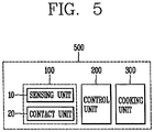
- the cooker 500 includes a driving unit 100 including a sensing unit 10 sensing a movement of a user who uses a cooker and a contact unit 20 switching a power circuit to which power is supplied from the outside and performing a closing operation on the basis of a sensing result from the sensing unit 10 to receive power, a cooking unit 300 performing a cooking operation of the cooker 500, and a control unit 200 driven by power supplied through the power circuit to control operations of the contact unit 20 and the cooking unit 300.
- a driving unit 100 including a sensing unit 10 sensing a movement of a user who uses a cooker and a contact unit 20 switching a power circuit to which power is supplied from the outside and performing a closing operation on the basis of a sensing result from the sensing unit 10 to receive power, a cooking unit 300 performing a cooking operation of the cooker 500, and a control unit 200 driven by power supplied through the power circuit to control operations of the contact unit 20 and the cooking unit 300.
- the cooker 500 may refer to a device for cooking food using an electric energy, such as a microwave oven, an oven, or an induction heating (IH) cooker.
- an electric energy such as a microwave oven, an oven, or an induction heating (IH) cooker.
- the cooker 500 may include a plurality of circuits to perform a cooking function.
- the cooker 500 may include the driving circuit 100 or the driving system 400 described above.
- the driving unit 100 receives power for driving the cooker 500
- the cooking unit 300 is driven by power received through the driving unit 100 to perform a cooking operation such that a cooking function of the cooker 500 may be performed
- the control unit 200 may be driven by power received through the driving unit 100 to control operations of the contact unit 20 and the cooking unit 300.
- the control unit 200 may be a micro controller unit (MCU) controlling driving and an operation of the cooker 500.
- MCU micro controller unit
- the cooking unit 300 may be driven by the driving system 400 to perform a cooking operation of the cooker 500.
- the cooker 500 includes the driving system 400 performing driving and the cooking unit 300 performing cooking, and the cooking unit 300 is driven through the driving system 400 to perform cooking.
- the sensing unit 10 senses a movement of the user of the cooker 500, and the contact unit 20 performs a closing operation on the basis of the sensing result from the sensing unit 10 so that the power circuit, to which power is supplied from the outside, is closed to receive power.
- the driving circuit 100 is connected to the power circuit to which power is supplied from the outside, to allow power to be supplied to the cooker including the control unit 200.
- the sensing unit 10 may be positioned on a front portion of the cooker.
- the sensing unit 10 may infrared-sense a movement of the user of the cooker and generate an operation signal regarding controlling of a closing operation of the contact unit 20 according to the sensing result.
- the sensing unit 10 may include an infrared sensor 11 infrared-sensing a movement of the user.
- the infrared sensor 11 may refer to a passive infrared ray sensor sensing a change in infrared rays according to a movement of a human body and converting the sensed change into an amount of electricity.
- the sensing unit 10 may sense a movement of the user on the front portion of the cooker through the infrared sensor 11.
- the sensing unit 10 may further include a signal generating unit 12 generating an operation signal regarding controlling of a closing operation of the contact unit 20.
- the sensing unit 10 may generate the operation signal though the signal generating unit 12.
- the predetermined period of time may be a period of time during which the user is supposed to use the cooker.
- the predetermined period of time may be a period of time of 3 seconds or greater.
- the sensing unit 10 senses a movement of the user on the front portion of the cooker for a predetermined period of time through the infrared sensor 11, and in some implementations, in which a movement of the user is sensed for the predetermined period of time, since the user is supposed to use the cooker, the sensing unit 10 may generate the operation signal according to the sensing result for the predetermined period of time through the signal generating unit 12.
- the sensing unit 10 may generate the operation signal and transmit the generated operation signal to the contact unit 20.
- the contact unit 20 may receive the operation signal from the sensing unit 10.
- the contact unit 20 switches the power circuit supplying power from the outside to the cooker 500, so that power may be supplied or cut off.
- the contact unit 20 may allow power to be supplied to enable the cooking unit 300 and the control unit 200 to be driven.
- the contact unit 20 may be an physical contact (a contact or switch) which is open at normal times and which is closed at the time of operation.
- the contact unit 200 is open at normal times to prevent power from being supplied, and is closed at the time of operation to allow power to be supplied.
- the contact unit 20 may receive the generated operation signal from the sensing unit 10, perform a closing operation on the basis of the operation signal, and maintain the closing operation on the basis of a signal generated by the control unit 200.
- the contact unit 10 may receive the operation signal, which has been generated on the basis of a result of sensing a movement of the user on the front portion of the cooker 500 for a predetermined period of time, from the sensing unit 10 and perform a closing operation to allow power to be supplied, and when the control unit 200 is driven upon receiving power, the contact unit 10 may maintain the closing operation under the control of the control unit 200.
- the contact unit 20 maintains the closing operation on the basis of a signal generated by the control unit 200, such that power supply to the cooking unit 300 and the control unit 200 is maintained.
- the contact unit 20 is returned to an open state when there is no signal generated by the sensing unit 10 or the control unit 200.
- power supply is not required so a signal is not generated by the sensing unit 10 or the control unit 200, the contact unit 20 may be returned from the closing operation to the open state so that power may not be supplied.
- the cooking unit 300 is driven by power supplied through the power circuit.
- an operation of the cooking unit 300 may be controlled by the control unit 200.
- the cooking unit 300 may perform a cooking operation on food as a cooking target.
- the cooking unit 300 may be controlled by the control unit to perform a cooking function to heat food.
- the control unit 200 may control the cooking unit 300 to heat a cooking container positioned at an upper portion of the cooker 500 to 100°C.
- IH induction heating
- the control unit 200 is driven by power supplied through the power circuit.
- control unit 200 After the control unit 200 is driven by power supplied through the power circuit, the control unit 200 may generate a sustain signal for controlling maintaining the closing operation of the contact unit 20.
- control unit 200 after the control unit 200 is driven by power supplied through the power circuit, the control unit 200 generates the sustain signal to maintain power supply through the power circuit to thus control the contact unit 20.
- control unit 200 may control the contact unit 20 to maintain the closing operation, whereby power supplied through the power circuit may be maintained to maintain the driving.
- control unit 200 may control an operation of the cooking unit 300.
- control unit 200 since the control unit 200 is driven upon receiving power through the power circuit, the control unit 200 may control driving and operation of the cooker.
- the control unit 200 may control an operation of the cooker such that a cooking function of the cooker is executed.
- control unit may control an operation of the cooker to perform a cooking function corresponding to a user input.
- control unit 200 may control the contact unit 20 to maintain the closing operation of the contact unit 20.
- control unit 200 may control the contact unit 20 to maintain the closing operation of the contact unit 20 such that power supply to the cooker is maintained.
- a circuit configuration of the cooker 500 described above may have a form as illustrated in FIG. 7 .
- the contact unit 20 of the driving unit performs a closing operation on the basis of signals generated by the sensing unit 10 of the driving unit 100 and the control unit 200.
- the sensing unit 10, the control unit 200, and the contact unit 20 is configured as an OR gate in which an output is performed when there are one or more inputs.
- the sensing unit 10 and the control unit 200 are connected to an input of the OR gate, and an output of the OR gate is connected to the contact unit 20, and accordingly, when the sensing unit 10 or the control unit 200 generates a signal, the contact unit 20 may perform a closing operation.
- the sensing unit 10 senses a movement of the user on a front portion of the cooker 500
- the sensing unit 10 generates the operation signal
- the operation signal is transmitted to the contact unit 20
- the contact unit 20 performs a closing operation such that the power circuit to which power is supplied from the outside is closed. Since the power circuit is closed, power is supplied to the cooking unit 300 and the control unit 200, and thus, the control unit 200 may be driven.
- control unit 200 After the control unit 200 is driven, the control unit 200 generates the sustain signal to maintain the closing operation of the contact unit 20 in order to continuously receive power, and when the sustain signal is transmitted to the contact unit 20, the contact unit 20 maintains the closing operation, and thus, power supply to the control unit 200 is maintained, whereby driving of the control unit 200 may be maintained.
- control unit 200 After driving of the control unit 200 is maintained, the control unit 200 controls an operation of the cooking unit 300 to perform a cooking function of the cooker 500, and in order to continuously receive power while the cooking unit 300 is being operated, the control unit 200 may control the contact unit 200 to maintain the closing operation.
- FIGS. 8-11 illustrate example methods for driving a cooker.
- a method for driving a cooker (hereinafter, referred to as a "driving method") is a method for driving the cooker 500 including the sensing unit 10 sensing a movement of a user of the cooker 500, the cooking unit 300 performing a cooking operation of the cooker 500, and the control unit 200 driven by power supplied through the power circuit to control operations of the contact unit 20 and the cooking unit 300.
- the driving method may be the method for driving the cooker 500 described above.
- the driving method includes: step (S10) in which the sensing unit 10 senses a movement of a user of the cooker 500, step (S20) in which the contact unit 20 performs a closing operation on the basis of the sensing result, step (S30) in which the cooking unit 300 and the control unit 200 are driven with power supplied through the power circuit, step (S40) in which the control unit 200 controls an operation of the contact unit 20 to maintain the closing operation, and step (S50) in which driving of the cooking unit 300 and the control unit 200 is maintained by maintaining power supplied through the power circuit.
- Step (S10) of sensing a movement of a user of the cooker 500 is performed by the sensing unit 10.
- step (S10) of sensing a movement of the user of the cooker 500 a movement of the user on the front portion of the cooker 500 may be sensed through the sensing unit 10 positioned on the front portion of the cooker 500.
- step (S10) of sensing a movement of the user of the cooker 500 may include step (S11) of infrared-sensing a movement of the user of the cooker 500, step (S12) of generating an operation signal regarding controlling of a closing operation of the contact unit 20 according to the sensing result, and step (S13) of transmitting the operation signal to the contact unit 20.
- step (S11) of infrared-sensing a movement of the user of the cooker 500 the sensing unit 10 may infrared-sense a movement of the user on the front portion of the cooker 500.
- step (S12) of generating an operation signal the sensing unit 10 may generate an operation signal regarding controlling of a closing operation of the contact unit 20 according to the sensing result.
- step (S12) when a movement of the user of the cooker 500 is sensed for a predetermined period of time, the sensing unit 10 may generate the operation signal.
- the predetermined period of time may be a period of time during which the user is supposed to use the cooker 500.
- the predetermined period of time may be a period of time of three seconds or more.
- step (S13) of transmitting the operation signal to the contact unit 20 the sensing unit 10 transmits the operation signal to the contact unit 20.
- Step (S20) of performing a closing operation on the basis of the sensing result is performed through the contact unit 20.
- step (S20) of performing a closing operation on the basis of the sensing result the contact unit 20 performs a closing operation on the basis of a signal transmitted from the sensing unit 10 to close the power circuit which receives power from the outside.
- step (S20) of performing a closing operation on the basis of the sensing result the contact unit 20 switches the power circuit which receives power from the outside to supply power to the cooking unit 300 and the control unit 200 or to cut off power supply thereto.
- Step (S30) of driving the cooking unit 300 and the control unit 200 is performed through the cooking unit 300 and the control unit 200 upon receiving power as the contact unit 20 performs a closing operation.
- step (S30) of driving the cooking unit 300 and the control unit 200 the cooking unit 300 and the control unit 200 is provided with power so as to be driven.
- Step (S40) of controlling an operation of the contact unit 20 is performed through the control unit 200.
- step (S40) of controlling an operation of the contact unit 20 may include step (S41) of generating a sustain signal regarding controlling of maintaining a closing operation of the contact unit 20 and step (S42) of transmitting the sustain signal to the contact unit 20.
- step (S41) of generating a sustain signal after the control unit 200 is driven by power supplied through the power circuit, the control unit 200 may generate a sustain signal regarding controlling of maintaining the closing operation of the contact unit 20.
- step (S42) of transmitting the sustain signal to the contact unit 20 the control unit 20 may transmit the sustain signal to the contact unit 20.
- step (S40) of controlling the operation of the contact unit 20 after the controller 200 is driven with power supplied through the power circuit, the control unit 200 may generate the sustain signal to maintain power supply through the power circuit to thus control the contact unit 20.
- Step (S50) of maintaining driving of the cooking unit 300 and the control unit 200 is performed through the control unit 200 maintained in driving as power supplied through the power circuit is maintained.
- step (S50) of maintaining driving of the cooking unit 300 and the control unit 200 the contact unit 20 maintains the closing operation on the basis of a signal generated by the control unit 200 such that power supply to the cooking unit 300 and the control unit 200 is maintained.
- Step (S50) of maintaining driving of the cooking unit 300 and the control unit 200 may include step (S51) in which the control unit 200 controls an operation of the cooking unit 300 and step (S52) in which, while the control unit 200 controls the operation of the cooking unit 300, the control unit 200 controls the contact unit 20 to maintain the closing operation.
- step (S51) of controlling an operation of the cooking unit 300 in a state in which driving of the control unit 200 is maintained by maintaining power supplied through the power circuit, an operation of the cooking unit 300 may be controlled.
- control unit 200 may control an operation of the cooking unit 300 such that a cooking function of the cooker 500 is performed.
- Step (S52) of controlling the contact unit 20 to maintain the closing operation while the control unit 200 controls an operation of the cooking unit 300, the contact unit 20 may be controlled to maintain the closing operation.
- step (S50) of maintaining driving of the cooking unit 300 and the control unit 200 the control unit 200 is driven upon receiving power through the power circuit to control driving and an operation of the cooker 500.
- the circuit for driving a cooker, the system for driving a cooker, the cooker, and the method for driving a cooker disclosed in the present disclosure may be applied to and implemented in power circuits and driving circuits of home appliances and power circuits and driving circuits of industrial electric equipment.
- the circuit for driving a cooker, the system for driving a cooker, the cooker, and the method for driving a cooker disclosed in the present disclosure may be applied to and implemented in power supply devices, power supply systems, driving devices, and driving system of home appliances and industrial electric equipment.
- the circuit for driving a cooker, the system for driving a cooker, the cooker, and the method for driving a cooker disclosed in the present disclosure may be applied to and implemented power supply methods and driving methods of home appliances and industrial electric equipment.
- the circuit for driving a cooker, the system for driving a cooker, the cooker, and the method for driving a cooker disclosed in the present disclosure may be applied to and implemented in induction heating cookers using electric energy.
- the circuit for driving a cooker the system for driving a cooker, the cooker, and the method for driving a cooker disclosed in the present disclosure, since power is supplied according to a result of sensing a movement of a user, consumption of standby power may be reduced.
- the circuit for driving a cooker the system for driving a cooker, the cooker, and the method for driving a cooker disclosed in the present disclosure, since power is supplied according to a result of sensing a movement of a user, insulation of cooker and electric leakage may be reduced.
- the circuit for driving a cooker the system for driving a cooker, the cooker, and the method for driving a cooker disclosed in the present disclosure, since insulation of cooker and electric leakage are reduced, usage stability of a cooker may be increased.
- the circuit for driving a cooker the system for driving a cooker, the cooker, and the method for driving a cooker disclosed in the present disclosure, since power is supplied according to a result of sensing a movement of the user, power supply and driving of a cooker may be automatically performed.
- the circuit for driving a cooker the system for driving a cooker, the cooker, and the method for driving a cooker disclosed in the present disclosure, since power supply and driving of a cooker are automatically performed, usage convenience of a cooker may be increased.
Description
- The present disclosure relates to a circuit for driving a cooker, a system for driving a cooker, a cooker, and a method for driving a cooker, and particularly, to a system for driving a cooker by supplying power according to a result of sensing a movement of a user, a cooker, and a method for driving a cooker.
- A cooker is one of home appliances for cooking food within a container by heating the container using a heat source. Cookers may be classified according hot sources. For example, cookers include a gas range and a gas oven using a gas, and a microwave oven, an electric oven, and an induction heating cooker using electric power. The microwave oven or the electric oven are cookers cooking food using microwaves, in which a microwave generated by a magnetron to which a high voltage is applied is irradiated to a food item within a cooking chamber through a wave guide to vibrate water molecules contained in the food item to generate heat energy , thus cooling the food item.
- Cookers are used in most houses such that a power plug connected to a product is connected to an external alternating current (AC) power source, and in this state, a start switch, or the like, is selectively used, and after the cooker is used, the power plug continues to be put in an electrical outlet.
- In a state in which the power plug is continuously put in the electric outlet, power is consumed to continuously operate a microcomputer and a display unit for monitoring an operational state of the microwave oven, and when standby power consumption is accumulated for a long period of time, not a little power consumption is caused.
- In order to solve the problem, a related art uses a mechanical switch. In this case, however, since the mechanical switch is used, there is a limitation in that the mechanical switch is operated manually, and in order to cut off standby power and supply power, a user should turned on and turned off the switch each time, degrading user convenience.
-
US 2005/0109333 A1 discloses a safety device for regulating electrical power to a cooking appliance, comprising a control module having a power routing means, a power supply means, a load current sensing means for detecting a load current to the cooking appliance and a power relay means for controlling the electrical current to the cooking appliance, and a sensor module located adjacent to the cooking appliance for observation by an appliance operator and connected to the control module. The sensor module governs the production of the electrical current to the cooking appliance, and has a monitoring means, a distance sensing means, a timer means for showing elapsed cooking time, and a light emitting means. The monitoring means is responsive to outputs of the distance sensing means and includes a timer assembly programmed to a predetermined period of time for responding to the distance sensing means detecting the presence of the appliance operator. -
WO 2011/133119 A2 discloses a zero power standby system for controlling electric appliances that is able to wait for switch on instructions without any power consumption. This is done by a remote controller transmitting power in form of either electromagnetic field, light, or audio signal to a power receiving section of a control signal receiving device. The power receiving section will then use the received power to force a multi-switch section to connect between a power supply and a control signal receiving section and a control signal processing section and put the appliance into its usual running mode. When a user desires to turn off the electric appliance, the system stop supplying power to the control signal receiving section and the control signal processing section by turning off multi-switch section and put the electric appliance back to its zero power standby mode. -
EP 1 276 351 A2 discloses a microwave oven with a proximity detector for sensing the presence of a person. The operation of the oven is modified in dependence on the presence of a person. For example, the cooking chamber light is turned off when no one is present and the microwave generator is stopped when someone is present.WO 2007/139521 A2 discloses a device for the protection of stand-alone thermic household appliances, especially cooking stoves and hotplates against unwanted consequences of untimely interference and against unwanted interference of children. A household appliance has a sensor provided on its upper external edge detecting presence of a person under an angle of between approx. 30° and approx. 80° upwards, and has a clock or rather a timer with a predetermined switch-off time, preferably 15 minutes, which is triggered by the sensor. When the sensor detects presence of a person, it triggers the clock and unlocks operating controls, when the person removes himself, the sensor locks the operating controls thus starting a time interval. -
DE 101 30 198 A1 discloses a stove timer having a lighting display means that is switchable. In order to achieve energy savings and life extension of the display device the stove timer has an integrated sensor, which switches on the lighting via a transmitter, when a user approaches the stove. An evaluation electronics switches off the light with a time delay after the last senses user approach. - In addition, in terms of usage of cookers, in general users do not turn on or turn off the switch each time, and here, in a case in which users do not turn off the switch, standby power is continuously consumed, failing to become a basic alternative for reducing standby power consumption.
- Therefore, an aspect of the detailed description is to provide a circuit for driving a cooker, capable of reducing standby power consumption and increasing user convenience and stability of a cooker, a system for driving a cooker, a cooker, and a method for driving a cooker.
- The above identified problems are solved by the features of the independent claims. Advantageous embodiments are derived from the dependent claims.
- In an embodiment of the present disclosure, the sensing unit may be positioned on a front portion of the cooker.
- In an embodiment of the present disclosure, the sensing unit may include an infrared sensor configured to infrared-sense a movement of the user.
- In an embodiment of the present disclosure, the sensing unit may further include a signal generating unit configured to generate an operation signal regarding controlling of the closing operation of the contact unit according to the sensing result.
- In an embodiment of the present disclosure, when a movement of the user of the cooker is sensed for a predetermined period of time, the signal generating unit may generate the operation signal.
- Preferably, a cooker may include: a driving unit including a sensing unit configured to sense a movement of a user of a cooker and a contact unit configured to switch a power circuit to which power is supplied from the outside and perform a closing operation on the basis of a sensing result from the sensing unit to receive power; a cooking unit configured to perform a cooking operation of the cooker; and a control unit configured to be driven by power supplied through the power circuit to control operations of the contact unit and the cooking unit.
- In an embodiment of the present disclosure, after the control unit is driven by power supplied through the power circuit, the control unit may control the contact unit to maintain the closing operation, whereby power supplied through the power circuit is maintained to maintain driving.
- In an embodiment of the present disclosure, after driving of the control unit is maintained by maintaining power supplied through the power circuit, the control unit may control an operation of the cooker.
- In an embodiment of the present disclosure, while the control unit controls the operation of the cooker, the control unit may control the contact unit to maintain the closing operation.
- In an embodiment of the present disclosure, the sensing of a movement of the user of the cooker may include: infrared-sensing a movement of the user of the cooker; generating an operation signal regarding controlling of the closing operation of the contact unit according to the sensing result; and transmitting the operation signal to the contact unit.
- In an embodiment of the present disclosure, in the generating of the operation signal, when a movement of the user of the cooker is sensed for a predetermined period of time, the operation signal may be generated.
- In an embodiment of the present disclosure, the maintaining of the driving of the cooking unit and the control unit may include: controlling, by the control unit, an operation of the cooking unit; and controlling, by the control unit, the contact unit to maintain the closing operation, while controlling the operation of the cooking unit.
- According to the circuit for driving a cooker, the system for driving a cooker, the cooker, and the method for driving a cooker disclosed in the present disclosure, since power is supplied according to a result of sensing a movement of a user, consumption of standby power may be reduced.
- According to the circuit for driving a cooker, the system for driving a cooker, the cooker, and the method for driving a cooker disclosed in the present disclosure, since power is supplied according to a result of sensing a movement of a user, insulation of cooker and electric leakage may be reduced.
- According to the circuit for driving a cooker, the system for driving a cooker, the cooker, and the method for driving a cooker disclosed in the present disclosure, since insulation of cooker and electric leakage are reduced, usage stability of a cooker may be increased.
- According to the circuit for driving a cooker, the system for driving a cooker, the cooker, and the method for driving a cooker disclosed in the present disclosure, since power is supplied according to a result of sensing a movement of the user, power supply and driving of a cooker may be automatically performed.
- According to the circuit for driving a cooker, the system for driving a cooker, the cooker, and the method for driving a cooker disclosed in the present disclosure, since power supply and driving of a cooker are automatically performed, usage convenience of a cooker may be increased.
- Further scope of applicability of the present application will become more apparent from the detailed description given hereinafter. However, it should be understood that the detailed description and specific examples, while indicating preferred embodiments of the invention, are given by way of illustration only, since various changes and modifications within the scope of the invention will become apparent to those skilled in the art from the detailed description.
- The accompanying drawings, which are included to provide a further understanding of the invention and are incorporated in and constitute a part of this specification, illustrate exemplary embodiments and together with the description serve to explain the principles of the invention.
- In the drawings:
-
FIG. 1 is a view illustrating a configuration of a circuit for driving a cooker disclosed in the present disclosure. -
FIG. 2 is a view illustrating a configuration according to an embodiment of a circuit for driving a cooker disclosed in the present disclosure. -
FIG. 3 is a view illustrating a configuration of a system for driving a cooker disposed in the present disclosure. -
FIG. 4 is a view illustrating a configuration according to an embodiment of a system for driving a cooker disclosed in the present disclosure. -
FIG. 5 is a view illustrating a configuration of a cooker disclosed in the present disclosure. -
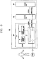
FIG. 6 is a view illustrating a configuration according to an embodiment of a cooker disclosed in the present disclosure. -
FIG. 7 is a view illustrating a concept of a circuit configuration according to an embodiment of a cooker disclosed in the present disclosure. -
FIG. 8 is a flow chart illustrating a method for driving a cooker disclosed in the present disclosure. -
FIG. 9 is a first flow chart illustrating an embodiment of a method for driving a cooker disclosed in the present disclosure. -
FIG. 10 is a second flow chart illustrating an embodiment of a method for driving a cooker disclosed in the present disclosure. -
FIG. 11 is a third flow chart illustrating an embodiment of a method for driving a cooker disclosed in the present disclosure. - The present disclosure may be applied to a circuit for driving a cooker, a system for driving a cooker, a cooker, and a method for driving a cooker. However, the technique disclosed in the present disclosure is not limited thereto and may be advantageously applied to and implemented in a power circuit and a driving circuit of every existing home appliance, a power circuit and a driving circuit of industrial electric equipment, a power supply device, a power supply system, a driving device, and a driving system of a home appliance and industrial electric equipment, and a power supply method and a driving method of a home appliance and industrial electric equipment to which a technical concept of the present disclosure may be applied.
- Terms used in the present specification are used only in order to describe specific exemplary embodiments rather than limiting the present invention.
- Hereinafter, the embodiments of the present invention will be described with reference to the accompanying drawings, in which like numbers refer to like elements throughout although the embodiments are different, and a description of the like elements a first embodiment will be used for those of the different embodiment.
- Hereinafter, a circuit for driving a cooker disclosed in the present disclosure will be described with reference to
FIGS. 1 and 2 . -
FIG. 1 is a view illustrating a configuration of a circuit for driving a cooker disclosed in the present disclosure. -
FIG. 2 is a view illustrating a configuration according to an embodiment of a circuit for driving a cooker disclosed in the present disclosure. - As illustrated in
FIG. 1 , acircuit 100 for driving a cooker (hereinafter, referred to as a "driving circuit") includes asensing unit 10 sensing a movement of a user who uses a cooker and acontact unit 20 switching a power circuit to which power is supplied from the outside and performing a closing operation on the basis of a sensing result from thesensing unit 10 to supply power to the cooker. - The driving
circuit 100 refers to a circuit for supplying power to drive the cooker. - The driving
circuit 100 may be a circuit included in the cooker. - The driving
circuit 100 is a circuit connected to the outside of the cooker and driving the cooker. - The driving
circuit 100 may be configured in the form of a module. - In the
driving circuit 100, thesensing unit 10 senses a movement of the user of the cooker, and thecontact unit 20 performs a closing operation on the basis of the sensing result from thesensing unit 10 so that the power circuit, to which power is supplied from the outside, is closed to allow power to be supplied to the cooker. - As illustrated in
FIG. 2 , the drivingcircuit 100 is connected to the power circuit to which power is supplied from the outside, to allow power to be supplied to the cooker. - The
sensing unit 10 may be positioned on a front portion of the cooker. - In some implementations, the
sensing unit 10 may sense a movement of the user on a front portion of the cooker. - The
sensing unit 10 may include aninfrared sensor 11 infrared-sensing a movement of the user. - The
infrared sensor 11 may be configured to identify movement of the user by sensing infrared light. - The
infrared sensor 11 may refer to a passive infrared ray sensor sensing a change in infrared rays according to a movement of a human body and converting the sensed change into an amount of electricity. - The
sensing unit 10 may sense a movement of the user on the front portion of the cooker through theinfrared sensor 11. - The
sensing unit 10 may further include asignal generating unit 12 generating an operation signal regarding controlling of a closing operation of thecontact unit 20. - The
signal generating unit 12 may be configured to generate the operation signal based on the infrared sensor identifying movement of the user. - In some implementations, the
sensing unit 10 may generate the operation signal according to a sensing result from theinfrared sensor 11 through thesignal generating unit 12. - The
signal generating unit 12 may generate the operation signal in a case in which a movement of the user of the cooker is sensed for a predetermined period of time. - The predetermined period of time may be a period of time during which the user is supposed to use the cooker.
- For example, the predetermined period of time may be a period of time of 3 seconds or greater.
- The
sensing unit 10 may sense a movement of the user on the front portion of the cooker for a predetermined period of time through theinfrared sensor 11, and in some implementations, in which a movement of the user is sensed for the predetermined period of time, since the user is supposed to use the cooker, thesensing unit 10 may generate the operation signal according to the sensing result for the predetermined period of time through thesignal generating unit 12. - The
sensing unit 10 may generate the operation signal and transmit the generated operation signal to thecontact unit 20. - The
contact unit 20 is configured to disconnect power that is received. - The
contact unit 20 is configured to provide to the cooker, power that is received from the power circuit in response to the operation signal from the sensing unit. - The
contact unit 20 may receive the operation signal from thesensing unit 10. - The
contact unit 20 switches the power circuit supply power from the outside to the cooker, so that power may be supplied to the cooker or power supply to the cooker may be cut off. - The
contact unit 20 may be an physical contact (a contact or switch) which is open at normal times and which is closed at the time of operation, or thecontact unit 20 may comprise a switch that is configured to be open except during operation of the cooker and is configured to close in response to the operation signal. - The
contact unit 20 is open at normal times not to supply power to the cooker, and is closed at the time of operation to supply power to the cooker. - Upon receiving the generated operation signal from the
sensing unit 10, thecontact unit 20 may perform a closing operation on the basis of the operation signal. - Upon receiving the operation signal, which has been generated on the basis of a result of sensing a movement of the user on the front portion of the cooker for a predetermined period of time, from the
sensing unit 10, thecontact unit 20 may perform a closing operation to supply power to the cooker. -
FIGS. 3 and 4 illustrate example systems for driving a cooker. - As illustrated in
FIG. 3 , asystem 400 for driving a cooker (hereinafter, referred to as a "driving system") includes adriving unit 100 including asensing unit 10 sensing a movement of a user and acontact unit 20 switching a power circuit to which power is supplied from the outside, and performing a closing operation on the basis of a sensing result from thesensing unit 10 to supply power to the cooker, and acontrol unit 200 driven by power supplied from the power circuit to control an operation of thecontact unit 20. - The
driving system 400 refers to a circuit system for driving the cooker. - The
driving system 400 may refer to a system including a plurality of circuits included in the cooker. - The
driving system 400 is a system including the drivingcircuit 100 described above. - In the
driving system 400, the drivingunit 100 allows power for driving the cooker to be supplied to the cooker, and thecontrol unit 200 is driven by power supplied through the drivingunit 100 to control an operation of thecontact unit 20 . - The driving
unit 100 may be a circuit included in the cooker. - The driving
unit 100 is a circuit connected to the outside of the cooker to enable the cooker to be driven. - The driving
unit 100 may be configured in the form of a module. - The
control unit 200 may be a circuit included in the cooker. - The
control unit 200 may be a micro controller unit (MCU) controlling driving and an operation of the cooker. - In the
driving unit 100, thesensing unit 10 senses a movement of the user of the cooker, and thecontact unit 20 performs a closing operation on the basis of the sensing result from thesensing unit 10 so that the power circuit, to which power is supplied from the outside, is closed to allow power to be supplied to the cooker. - As illustrated in
FIG. 4 , the drivingcircuit 100 is connected to the power circuit to which power is supplied from the outside, to allow power to be supplied to the cooker including thecontrol unit 200. - The
sensing unit 10 may be positioned on a front portion of the cooker. - The
sensing unit 10 may infrared-sense a movement of the user of the cooker and generate an operation signal regarding controlling of a closing operation of thecontact unit 20 according to the sensing result. - The
sensing unit 10 may be configured to output the operation signal based on sensed movement of a user. - The
sensing unit 10 may include aninfrared sensor 11 infrared-sensing a movement of the user. - The
infrared sensor 11 may refer to a passive infrared ray sensor sensing a change in infrared rays according to a movement of a human body and converting the sensed change into an amount of electricity. - The
sensing unit 10 may sense a movement of the user on the front portion of the cooker through theinfrared sensor 11. - The
sensing unit 10 may further include asignal generating unit 12 generating an operation signal regarding controlling of a closing operation of thecontact unit 20. - When a movement of the user of the cooker is sensed for a predetermined period of time, the
sensing unit 10 may generate the operation signal though thesignal generating unit 12. - The predetermined period of time may be a period of time during which the user is supposed to use the cooker.
- For example, the predetermined period of time may be a period of time of 3 seconds or greater.
- In some implementations, the
sensing unit 10 senses a movement of the user on the front portion of the cooker for a predetermined period of time through theinfrared sensor 11, and in some implementations, in which a movement of the user is sensed for the predetermined period of time, since the user is supposed to use the cooker, thesensing unit 10 may generate the operation signal according to the sensing result for the predetermined period of time through thesignal generating unit 12. - The
sensing unit 10 may generate the operation signal and transmit the generated operation signal to thecontact unit 20. - The
contact unit 20 may receive the operation signal from thesensing unit 10. - The
contact unit 20 switches the power circuit supplying power from the outside to the cooker, so that power may be supplied to the cooker or power supply to the cooker may be cut off. - The
contact unit 20 supplies power to the cooker to enable thecontrol unit 200 to be driven. - The
contact unit 20 may be an physical contact (a contact or switch) which is open at normal times and which is closed at the time of operation. - The
contact unit 20 is open at normal times not to supply power to the cooker, and is closed at the time of operation to supply power to the cooker. - Upon receiving the generated operation signal from the
sensing unit 10, thecontact unit 20 performs a closing operation on the basis of the operation signal and maintains the closing operation on the basis of a signal generated by thecontrol unit 200. - In some implementations, the
contact unit 10 may receive the operation signal, which has been generated on the basis of a result of sensing a movement of the user on the front portion of the cooker for a predetermined period of time, from thesensing unit 10, perform a closing operation on the basis of the operation signal to supply power to the cooker, and maintain the closing operation under the control of thecontrol unit 200 which is driven upon receiving power. - The
contact unit 20 maintains the closing operation on the basis of the signal generated by thecontrol unit 200 to maintain power supply to the cooker. - The
contact unit 20 is returned to an open state when there is no signal generated by thesensing unit 10 or thecontrol unit 200. - In some implementations, power supply to the cooker is not required so a signal is not generated by the
sensing unit 10 or thecontrol unit 200, thecontact unit 20 may be returned from the closing operation to a previous state (e.g., an open state) so that power may not be supplied. - The
control unit 200 is driven by power supplied through the power circuit. - The
control unit 200 is configured to, based on thecontrol unit 200 controlling the operation of the cooker, maintain thecontact unit 20 in a closed position. - After the
control unit 200 is driven by power supplied through the power circuit, thecontrol unit 200 may generate a sustain signal for controlling maintaining the closing operation of thecontact unit 20. - In some implementations, after the
control unit 200 is driven by power supplied through the power circuit, thecontrol unit 200 generates the sustain signal to maintain power supply through the power circuit to thus control thecontact unit 20. - The
control unit 200 controls thecontact unit 20 to maintain the closing operation, whereby power supplied through the power circuit may be maintained to maintain the driving. - After the power supplied through the power circuit is maintained to maintain the driving, the
control unit 200 may control an operation of the cooker. - In some implementations, since the
control unit 200 is driven upon receiving power through the power circuit, thecontrol unit 200 may control driving and operation of the cooker. - The
control unit 200 may control an operation of the cooker such that a cooking function of the cooker is executed. - For example, the control unit may control an operation of the cooker to perform a cooking function corresponding to a user input.
- While controlling the operation of the cooker, the
control unit 200 may control thecontact unit 20 to maintain the closing operation of thecontact unit 20. - In some implementations, while the cooking function of the cooker is being performed, the
control unit 200 may control thecontact unit 20 to maintain the closing operation of thecontact unit 20 such that power supply to the cooker is maintained. -
FIGS. 5 and6 illustrate of example cookers.FIG. 7 illustrates an example circuit of a cooker. - As illustrated in
FIG. 5 , thecooker 500 includes adriving unit 100 including asensing unit 10 sensing a movement of a user who uses a cooker and acontact unit 20 switching a power circuit to which power is supplied from the outside and performing a closing operation on the basis of a sensing result from thesensing unit 10 to receive power, acooking unit 300 performing a cooking operation of thecooker 500, and acontrol unit 200 driven by power supplied through the power circuit to control operations of thecontact unit 20 and thecooking unit 300. - The
cooker 500 may refer to a device for cooking food using an electric energy, such as a microwave oven, an oven, or an induction heating (IH) cooker. - The
cooker 500 may include a plurality of circuits to perform a cooking function. - The
cooker 500 may include the drivingcircuit 100 or thedriving system 400 described above. - In the
cooker 500, the drivingunit 100 receives power for driving thecooker 500, thecooking unit 300 is driven by power received through the drivingunit 100 to perform a cooking operation such that a cooking function of thecooker 500 may be performed, and thecontrol unit 200 may be driven by power received through the drivingunit 100 to control operations of thecontact unit 20 and thecooking unit 300. - The
control unit 200 may be a micro controller unit (MCU) controlling driving and an operation of thecooker 500. - The
cooking unit 300 may be driven by thedriving system 400 to perform a cooking operation of thecooker 500. - In some implementations, the
cooker 500 includes thedriving system 400 performing driving and thecooking unit 300 performing cooking, and thecooking unit 300 is driven through thedriving system 400 to perform cooking. - In the
driving unit 100, thesensing unit 10 senses a movement of the user of thecooker 500, and thecontact unit 20 performs a closing operation on the basis of the sensing result from thesensing unit 10 so that the power circuit, to which power is supplied from the outside, is closed to receive power. - As illustrated in
FIG. 6 , the drivingcircuit 100 is connected to the power circuit to which power is supplied from the outside, to allow power to be supplied to the cooker including thecontrol unit 200. - The
sensing unit 10 may be positioned on a front portion of the cooker. - The
sensing unit 10 may infrared-sense a movement of the user of the cooker and generate an operation signal regarding controlling of a closing operation of thecontact unit 20 according to the sensing result. - The
sensing unit 10 may include aninfrared sensor 11 infrared-sensing a movement of the user. - The
infrared sensor 11 may refer to a passive infrared ray sensor sensing a change in infrared rays according to a movement of a human body and converting the sensed change into an amount of electricity. - The
sensing unit 10 may sense a movement of the user on the front portion of the cooker through theinfrared sensor 11. - The
sensing unit 10 may further include asignal generating unit 12 generating an operation signal regarding controlling of a closing operation of thecontact unit 20. - When a movement of the user of the
cooker 500 is sensed for a predetermined period of time, thesensing unit 10 may generate the operation signal though thesignal generating unit 12. - The predetermined period of time may be a period of time during which the user is supposed to use the cooker.
- For example, the predetermined period of time may be a period of time of 3 seconds or greater.
- In some implementations, the
sensing unit 10 senses a movement of the user on the front portion of the cooker for a predetermined period of time through theinfrared sensor 11, and in some implementations, in which a movement of the user is sensed for the predetermined period of time, since the user is supposed to use the cooker, thesensing unit 10 may generate the operation signal according to the sensing result for the predetermined period of time through thesignal generating unit 12. - The
sensing unit 10 may generate the operation signal and transmit the generated operation signal to thecontact unit 20. - The
contact unit 20 may receive the operation signal from thesensing unit 10. - The
contact unit 20 switches the power circuit supplying power from the outside to thecooker 500, so that power may be supplied or cut off. - The
contact unit 20 may allow power to be supplied to enable thecooking unit 300 and thecontrol unit 200 to be driven. - The
contact unit 20 may be an physical contact (a contact or switch) which is open at normal times and which is closed at the time of operation. - The
contact unit 200 is open at normal times to prevent power from being supplied, and is closed at the time of operation to allow power to be supplied. - The
contact unit 20 may receive the generated operation signal from thesensing unit 10, perform a closing operation on the basis of the operation signal, and maintain the closing operation on the basis of a signal generated by thecontrol unit 200. - In some implementations, the
contact unit 10 may receive the operation signal, which has been generated on the basis of a result of sensing a movement of the user on the front portion of thecooker 500 for a predetermined period of time, from thesensing unit 10 and perform a closing operation to allow power to be supplied, and when thecontrol unit 200 is driven upon receiving power, thecontact unit 10 may maintain the closing operation under the control of thecontrol unit 200. - The
contact unit 20 maintains the closing operation on the basis of a signal generated by thecontrol unit 200, such that power supply to thecooking unit 300 and thecontrol unit 200 is maintained. - The
contact unit 20 is returned to an open state when there is no signal generated by thesensing unit 10 or thecontrol unit 200. - In some implementations, power supply is not required so a signal is not generated by the
sensing unit 10 or thecontrol unit 200, thecontact unit 20 may be returned from the closing operation to the open state so that power may not be supplied. - The
cooking unit 300 is driven by power supplied through the power circuit. - After the cooking unit is driven by power supplied through the power circuit, an operation of the
cooking unit 300 may be controlled by thecontrol unit 200. - The
cooking unit 300 may perform a cooking operation on food as a cooking target. - The
cooking unit 300 may be controlled by the control unit to perform a cooking function to heat food. - For example, when the
cooker 500 is an induction heating (IH) cooker, thecontrol unit 200 may control thecooking unit 300 to heat a cooking container positioned at an upper portion of thecooker 500 to 100°C. - The
control unit 200 is driven by power supplied through the power circuit. - After the
control unit 200 is driven by power supplied through the power circuit, thecontrol unit 200 may generate a sustain signal for controlling maintaining the closing operation of thecontact unit 20. - In some implementations, after the
control unit 200 is driven by power supplied through the power circuit, thecontrol unit 200 generates the sustain signal to maintain power supply through the power circuit to thus control thecontact unit 20. - After the
control unit 200 is driven by power supplied through the power circuit, thecontrol unit 200 may control thecontact unit 20 to maintain the closing operation, whereby power supplied through the power circuit may be maintained to maintain the driving. - After the power supplied through the power circuit is maintained to maintain the driving, the
control unit 200 may control an operation of thecooking unit 300. - In some implementations, since the
control unit 200 is driven upon receiving power through the power circuit, thecontrol unit 200 may control driving and operation of the cooker. - The
control unit 200 may control an operation of the cooker such that a cooking function of the cooker is executed. - For example, the control unit may control an operation of the cooker to perform a cooking function corresponding to a user input.
- While controlling the operation of the cooker, the
control unit 200 may control thecontact unit 20 to maintain the closing operation of thecontact unit 20. - In some implementations, while the cooking function of the cooker is being performed, the
control unit 200 may control thecontact unit 20 to maintain the closing operation of thecontact unit 20 such that power supply to the cooker is maintained. - A circuit configuration of the
cooker 500 described above may have a form as illustrated inFIG. 7 . - As illustrated in
FIG. 7 , in thecooker 500, thecontact unit 20 of the driving unit performs a closing operation on the basis of signals generated by thesensing unit 10 of thedriving unit 100 and thecontrol unit 200. - The
sensing unit 10, thecontrol unit 200, and thecontact unit 20 is configured as an OR gate in which an output is performed when there are one or more inputs. - The
sensing unit 10 and thecontrol unit 200 are connected to an input of the OR gate, and an output of the OR gate is connected to thecontact unit 20, and accordingly, when thesensing unit 10 or thecontrol unit 200 generates a signal, thecontact unit 20 may perform a closing operation. - As for a process of driving the
cooker 500, when thesensing unit 10 senses a movement of the user on a front portion of thecooker 500, thesensing unit 10 generates the operation signal, and when the operation signal is transmitted to thecontact unit 20, thecontact unit 20 performs a closing operation such that the power circuit to which power is supplied from the outside is closed. Since the power circuit is closed, power is supplied to thecooking unit 300 and thecontrol unit 200, and thus, thecontrol unit 200 may be driven. - After the
control unit 200 is driven, thecontrol unit 200 generates the sustain signal to maintain the closing operation of thecontact unit 20 in order to continuously receive power, and when the sustain signal is transmitted to thecontact unit 20, thecontact unit 20 maintains the closing operation, and thus, power supply to thecontrol unit 200 is maintained, whereby driving of thecontrol unit 200 may be maintained. - After driving of the
control unit 200 is maintained, thecontrol unit 200 controls an operation of thecooking unit 300 to perform a cooking function of thecooker 500, and in order to continuously receive power while thecooking unit 300 is being operated, thecontrol unit 200 may control thecontact unit 200 to maintain the closing operation. - When a signal is not generated by the
sensing unit 10 and thecontrol unit 200, it is a situation in which driving of thecooker 500 is not required. Thus, thecontact unit 20 is returned from the closing operation and the power circuit is open such that power supply to thecooker 500 may be cut off. - Through the driving of the process described above, when a cooking function is not performed (e.g., when power supply is not required), the power circuit is opened and power is not supplied, and thus, consumption of standby power of the
cooker 500 may be reduced and convenience of the user of thecooker 500 and stability may be increased. -
FIGS. 8-11 illustrate example methods for driving a cooker. - A method for driving a cooker (hereinafter, referred to as a "driving method") is a method for driving the
cooker 500 including thesensing unit 10 sensing a movement of a user of thecooker 500, thecooking unit 300 performing a cooking operation of thecooker 500, and thecontrol unit 200 driven by power supplied through the power circuit to control operations of thecontact unit 20 and thecooking unit 300. - The driving method may be the method for driving the
cooker 500 described above. - As illustrated in
FIG. 8 , the driving method includes: step (S10) in which thesensing unit 10 senses a movement of a user of thecooker 500, step (S20) in which thecontact unit 20 performs a closing operation on the basis of the sensing result, step (S30) in which thecooking unit 300 and thecontrol unit 200 are driven with power supplied through the power circuit, step (S40) in which thecontrol unit 200 controls an operation of thecontact unit 20 to maintain the closing operation, and step (S50) in which driving of thecooking unit 300 and thecontrol unit 200 is maintained by maintaining power supplied through the power circuit. - Step (S10) of sensing a movement of a user of the
cooker 500 is performed by thesensing unit 10. - In step (S10) of sensing a movement of the user of the
cooker 500, a movement of the user on the front portion of thecooker 500 may be sensed through thesensing unit 10 positioned on the front portion of thecooker 500. - As illustrated in
FIG. 9 , step (S10) of sensing a movement of the user of thecooker 500 may include step (S11) of infrared-sensing a movement of the user of thecooker 500, step (S12) of generating an operation signal regarding controlling of a closing operation of thecontact unit 20 according to the sensing result, and step (S13) of transmitting the operation signal to thecontact unit 20. - In step (S11) of infrared-sensing a movement of the user of the
cooker 500, thesensing unit 10 may infrared-sense a movement of the user on the front portion of thecooker 500. - In step (S12) of generating an operation signal, the
sensing unit 10 may generate an operation signal regarding controlling of a closing operation of thecontact unit 20 according to the sensing result. - In step (S12), when a movement of the user of the
cooker 500 is sensed for a predetermined period of time, thesensing unit 10 may generate the operation signal. - The predetermined period of time may be a period of time during which the user is supposed to use the
cooker 500. - For example, the predetermined period of time may be a period of time of three seconds or more.
- In step (S13) of transmitting the operation signal to the
contact unit 20, thesensing unit 10 transmits the operation signal to thecontact unit 20. - Step (S20) of performing a closing operation on the basis of the sensing result is performed through the
contact unit 20. - In step (S20) of performing a closing operation on the basis of the sensing result, the
contact unit 20 performs a closing operation on the basis of a signal transmitted from thesensing unit 10 to close the power circuit which receives power from the outside. - In step (S20) of performing a closing operation on the basis of the sensing result, the
contact unit 20 switches the power circuit which receives power from the outside to supply power to thecooking unit 300 and thecontrol unit 200 or to cut off power supply thereto. - Step (S30) of driving the
cooking unit 300 and thecontrol unit 200 is performed through thecooking unit 300 and thecontrol unit 200 upon receiving power as thecontact unit 20 performs a closing operation. - In step (S30) of driving the
cooking unit 300 and thecontrol unit 200, thecooking unit 300 and thecontrol unit 200 is provided with power so as to be driven. - Step (S40) of controlling an operation of the
contact unit 20 is performed through thecontrol unit 200. - As illustrated in
FIG. 10 , step (S40) of controlling an operation of thecontact unit 20 may include step (S41) of generating a sustain signal regarding controlling of maintaining a closing operation of thecontact unit 20 and step (S42) of transmitting the sustain signal to thecontact unit 20. - In step (S41) of generating a sustain signal, after the
control unit 200 is driven by power supplied through the power circuit, thecontrol unit 200 may generate a sustain signal regarding controlling of maintaining the closing operation of thecontact unit 20. - In step (S42) of transmitting the sustain signal to the
contact unit 20, thecontrol unit 20 may transmit the sustain signal to thecontact unit 20. - In some implementations, in step (S40) of controlling the operation of the
contact unit 20, after thecontroller 200 is driven with power supplied through the power circuit, thecontrol unit 200 may generate the sustain signal to maintain power supply through the power circuit to thus control thecontact unit 20. - Step (S50) of maintaining driving of the
cooking unit 300 and thecontrol unit 200 is performed through thecontrol unit 200 maintained in driving as power supplied through the power circuit is maintained. - In step (S50) of maintaining driving of the
cooking unit 300 and thecontrol unit 200, thecontact unit 20 maintains the closing operation on the basis of a signal generated by thecontrol unit 200 such that power supply to thecooking unit 300 and thecontrol unit 200 is maintained. - Step (S50) of maintaining driving of the
cooking unit 300 and thecontrol unit 200 may include step (S51) in which thecontrol unit 200 controls an operation of thecooking unit 300 and step (S52) in which, while thecontrol unit 200 controls the operation of thecooking unit 300, thecontrol unit 200 controls thecontact unit 20 to maintain the closing operation. - In step (S51) of controlling an operation of the
cooking unit 300, in a state in which driving of thecontrol unit 200 is maintained by maintaining power supplied through the power circuit, an operation of thecooking unit 300 may be controlled. - In step (S51) of controlling an operation of the
cooking unit 300, thecontrol unit 200 may control an operation of thecooking unit 300 such that a cooking function of thecooker 500 is performed. - Step (S52) of controlling the
contact unit 20 to maintain the closing operation, while thecontrol unit 200 controls an operation of thecooking unit 300, thecontact unit 20 may be controlled to maintain the closing operation. - In some implementations, in step (S50) of maintaining driving of the
cooking unit 300 and thecontrol unit 200, thecontrol unit 200 is driven upon receiving power through the power circuit to control driving and an operation of thecooker 500. - In some implementations, the circuit for driving a cooker, the system for driving a cooker, the cooker, and the method for driving a cooker disclosed in the present disclosure may be applied to and implemented in power circuits and driving circuits of home appliances and power circuits and driving circuits of industrial electric equipment.
- In some implementations, the circuit for driving a cooker, the system for driving a cooker, the cooker, and the method for driving a cooker disclosed in the present disclosure may be applied to and implemented in power supply devices, power supply systems, driving devices, and driving system of home appliances and industrial electric equipment.
- In some implementations, the circuit for driving a cooker, the system for driving a cooker, the cooker, and the method for driving a cooker disclosed in the present disclosure may be applied to and implemented power supply methods and driving methods of home appliances and industrial electric equipment.
- In some implementations, the circuit for driving a cooker, the system for driving a cooker, the cooker, and the method for driving a cooker disclosed in the present disclosure may be applied to and implemented in induction heating cookers using electric energy.
- According to the circuit for driving a cooker, the system for driving a cooker, the cooker, and the method for driving a cooker disclosed in the present disclosure, since power is supplied according to a result of sensing a movement of a user, consumption of standby power may be reduced.
- According to the circuit for driving a cooker, the system for driving a cooker, the cooker, and the method for driving a cooker disclosed in the present disclosure, since power is supplied according to a result of sensing a movement of a user, insulation of cooker and electric leakage may be reduced.
- According to the circuit for driving a cooker, the system for driving a cooker, the cooker, and the method for driving a cooker disclosed in the present disclosure, since insulation of cooker and electric leakage are reduced, usage stability of a cooker may be increased.
- According to the circuit for driving a cooker, the system for driving a cooker, the cooker, and the method for driving a cooker disclosed in the present disclosure, since power is supplied according to a result of sensing a movement of the user, power supply and driving of a cooker may be automatically performed.
- According to the circuit for driving a cooker, the system for driving a cooker, the cooker, and the method for driving a cooker disclosed in the present disclosure, since power supply and driving of a cooker are automatically performed, usage convenience of a cooker may be increased.
Claims (11)
- A system (400) for driving a cooker (500), the system (400) comprising:a driving unit (100) including a sensing unit (10) configured to sense a movement of a user of a cooker (500) and a contact unit (20) configured to switch a power circuit to which power is supplied from the outside and perform a closing operation on the basis of a sensing result from the sensing unit (10) to allow power to be supplied to the cooker (500); anda control unit (200) configured to be driven by power supplied through the power circuit to control an operation of the contact unit (20),characterized in thatthe contact unit (20) is a normally-open contact that is closed at a time of operation;the contact unit (20) is configured to perform the closing operation on the basis of an operation signal generated by the sensing unit (10) and to maintain the closing operation on the basis of a signal generated by the control unit (200);wherein when no signal is generated by the sensing unit (10) or the control unit (200), the contact unit (20) is returned from the closing operation to an open state so that power to the control unit (200) is cut off;wherein the sensing unit (10), the control unit (200), and the contact unit (20) are connected to an OR gate in which an output is performed when there are one or more inputs,wherein the sensing unit (10) and the control unit (200) are connected to different inputs of the OR gate, and an output of the OR gate is connected to the contact unit (20), andwherein when the sensing unit (10) or the control unit (200) generates a signal, the contact unit (20) performs the closing operation.
- The system (400) of claim 1, wherein the sensing unit (10) is positioned on a front portion of the cooker (500), infrared-senses a movement of the user of the cooker (500) and generates the operation signal regarding controlling of the closing operation of the contact unit(20) according to the sensing result.
- The system (400) of one of claims 1 and 2, wherein when a movement of the user of the cooker (500) is sensed for a predetermined period of time, the sensing unit (10) generates the operation signal.
- A cooker (500) comprising:the system (400) according to one of the claims 1 to 3; anda cooking unit (300) configured to perform a cooking operation of the cooker (500).
- The cooker (500) of claim 4, wherein after the control unit (200) is driven by power supplied through the power circuit, the control unit (200) controls the contact unit (20) to maintain the closing operation, and as the driving of the control unit (200) is maintained by maintaining power supplied through the power circuit, the control unit (200) controls an operation of the cooker (500).
- The cooker (500) of claim 5, wherein while the control unit (200) controls the operation of the cooker (500), the control unit (200) controls the contact unit (20) to maintain the closing operation.
- A method for driving a cooker (500) including: a driving unit (100) including a sensing unit(10) configured to sense a movement of a user of a cooker (500) and a contact unit (20) configured to switch a power circuit to which power is supplied from the outside; a cooking unit (300) configured to perform a cooking operation of the cooker (500); and a control unit (200) configured to be driven by power supplied through the power circuit to control operations of the contact unit (20) and the cooking unit (200), the method comprising:sensing, by the sensing unit (10), a movement of a user of the cooker (500);performing, by the contact unit (20), a closing operation on the basis of the sensing result;driving the cooking unit (300) and the control unit (200) with power supplied through the power circuit;controlling, by the control unit (200), an operation of the contact unit (20) to maintain the closing operation; andmaintaining driving of the cooking unit (300) and the control unit (200) by maintaining power supplied through the power circuit,the method being characterized bythe contact unit (20) being a normally-open contact that closes at a time of operation;performing, by the contact unit (20), the closing operation on the basis of an operation signal generated by the sensing unit (10) and maintaining, by the contact unit (20), the closing operation on the basis of a signal generated by the control unit (200);wherein when no signal is generated by the sensing unit (10) or the control unit (200), returning the contact unit (20) from the closing operation to an open state so that power to the control unit (200) is cut off;wherein the sensing unit (10), the control unit (200), and the contact unit (20) are connected to an OR gate in which an output is performed when there are one or more inputs,wherein the sensing unit (10) and the control unit (200) are connected to different inputs of the OR gate, and an output of the OR gate is connected to the contact unit (20), and
wherein when the sensing unit (10) or the control unit (200) generates a signal, the contact unit (20) performs the closing operation. - The method of claim 7, wherein the sensing of a movement of the user of the cooker (500) comprises:infrared-sensing a movement of the user of the cooker (500);generating an operation signal regarding controlling of the closing operation of the contact unit (20) according to the sensing result; andtransmitting the operation signal to the contact unit (20).
- The method of claim 8, wherein, in the generating of the operation signal, when a movement of the user of the cooker (500) is sensed for a predetermined period of time, the operation signal is generated.
- The method of one of claims 7 to 9, wherein the controlling of the operation of the contact unit (20) comprises:generating a sustain signal regarding controlling maintaining of the closing operation of the contact unit (20); andtransmitting the sustain signal to the contact unit (20).
- The method of one of claims 7 to 10, wherein the maintaining of the driving of the cooking unit (300) and the control unit (200) comprises:controlling, by the control unit (200), an operation of the cooking unit (300); andcontrolling, by the control unit (200), the contact unit (20) to maintain the closing operation, while controlling the operation of the cooking unit (300).
Applications Claiming Priority (1)
| Application Number | Priority Date | Filing Date | Title |
|---|---|---|---|
| KR1020140191051A KR101635048B1 (en) | 2014-12-26 | 2014-12-26 | Circuit for driving of cooker, system for driving of cooker, cooker and method for driving of cooker |
Publications (2)
| Publication Number | Publication Date |
|---|---|
| EP3038431A1 EP3038431A1 (en) | 2016-06-29 |
| EP3038431B1 true EP3038431B1 (en) | 2020-04-22 |
Family
ID=54979582
Family Applications (1)
| Application Number | Title | Priority Date | Filing Date |
|---|---|---|---|
| EP15202268.7A Active EP3038431B1 (en) | 2014-12-26 | 2015-12-23 | Circuit for driving cooker, system for driving cooker, cooker, and method for driving cooker |
Country Status (4)
| Country | Link |
|---|---|
| US (1) | US10925126B2 (en) |
| EP (1) | EP3038431B1 (en) |
| KR (1) | KR101635048B1 (en) |
| CN (1) | CN105725818A (en) |
Families Citing this family (3)
| Publication number | Priority date | Publication date | Assignee | Title |
|---|---|---|---|---|
| US20190082885A1 (en) * | 2016-03-09 | 2019-03-21 | Koninklijke Philips N.V. | An air-frying cooker and a method of cleaning an air-frying cooker |
| CN110045639A (en) * | 2018-01-17 | 2019-07-23 | 佛山市顺德区美的电热电器制造有限公司 | Cookware and its operating system, operating system awakening method |
| DE102020209940B4 (en) * | 2020-08-06 | 2022-11-03 | E.G.O. Elektro-Gerätebau GmbH | Method of operating a hob |
Family Cites Families (11)
| Publication number | Priority date | Publication date | Assignee | Title |
|---|---|---|---|---|
| US4820891A (en) * | 1986-11-29 | 1989-04-11 | Kabushiki Kaisha Toshiba | Induction heated cooking apparatus |
| JPH06300280A (en) * | 1993-04-13 | 1994-10-28 | Toshiba Corp | Heating cooker |
| JPH10300100A (en) * | 1997-04-24 | 1998-11-13 | Sanyo Electric Co Ltd | Heating cooker |
| US6294994B1 (en) * | 1999-03-15 | 2001-09-25 | Wendy Hoellerich | Appliance attendance monitoring apparatus |
| DE10130198B4 (en) * | 2001-06-22 | 2016-10-13 | Diehl Ako Stiftung & Co. Kg | Cooker timer |
| KR100782982B1 (en) * | 2001-07-11 | 2007-12-07 | 삼성전자주식회사 | Microwave oven and method thereof |
| JP2004293953A (en) * | 2003-03-27 | 2004-10-21 | Tokyo Gas Co Ltd | Cooking stove with human detection sensor |
| US20050109333A1 (en) * | 2003-11-21 | 2005-05-26 | Thomas Lowell R. | Safety device for regulating electrical power to a cooking appliance |
| SI22307A (en) * | 2006-05-30 | 2007-12-31 | Bc2222 D.O.O. | Device for protection of free-standing thermal household appliances |
| CA2567691A1 (en) * | 2006-11-09 | 2008-05-09 | Georges Dufour | Wireless smoke detector power cut-off system |
| GB2492024A (en) * | 2010-04-22 | 2012-12-19 | Nat Science And Technology Dev Agency | System with zero power standby mode for controlling electric apparatus |
-
2014
- 2014-12-26 KR KR1020140191051A patent/KR101635048B1/en active IP Right Grant
-
2015
- 2015-12-23 EP EP15202268.7A patent/EP3038431B1/en active Active
- 2015-12-25 CN CN201510993914.7A patent/CN105725818A/en active Pending
- 2015-12-28 US US14/979,761 patent/US10925126B2/en active Active
Non-Patent Citations (1)
| Title |
|---|
| None * |
Also Published As
| Publication number | Publication date |
|---|---|
| CN105725818A (en) | 2016-07-06 |
| US20160183711A1 (en) | 2016-06-30 |
| EP3038431A1 (en) | 2016-06-29 |
| KR101635048B1 (en) | 2016-06-30 |
| US10925126B2 (en) | 2021-02-16 |
Similar Documents
| Publication | Publication Date | Title |
|---|---|---|
| RU2369989C2 (en) | Blocking of stove for food cooking | |
| CA2755100C (en) | Lockout system for surface burners of a cooking appliance | |
| WO2009037783A1 (en) | Cooling apparatus for electromagnetic induction heating cooker | |
| EP3038431B1 (en) | Circuit for driving cooker, system for driving cooker, cooker, and method for driving cooker | |
| KR101626490B1 (en) | Cooking appliance and Method for controling it | |
| US20100109887A1 (en) | Systems, methods, and apparatus for automatically disabling appliances in response to a smoke detector | |
| EP2934064B1 (en) | Power management for home appliances | |
| US10251216B2 (en) | Cooking appliance and control method of the same | |
| CN204734329U (en) | Cooking utensil | |
| JP5262971B2 (en) | Cooker | |
| US10165625B2 (en) | Cooking appliance and controlling method thereof | |
| CN103353775B (en) | The intelligent temperature control induction installation of electrothermal load | |
| CN209770018U (en) | Cooking stove device for wireless power supply of kitchen electrical appliance | |
| CN109730521B (en) | A cooking stove device for kitchen electrical apparatus wireless power supply | |
| KR20170068994A (en) | Control method of electric cooker | |
| CN103822257A (en) | Convenient timing gas-cooker | |
| CN203823821U (en) | Gas stove capable of realizing timing conveniently | |
| KR102248633B1 (en) | System for controlling hybrid range hood system | |
| JP6855638B2 (en) | Separate type cookware and its control method | |
| KR101592026B1 (en) | A cooker and a method of controlling the same | |
| CN1888568B (en) | Safety device for microwave oven | |
| KR20000043279A (en) | Method for saving power of microwave oven | |
| CN205072651U (en) | Energy -saving electric cooker | |
| KR100674571B1 (en) | Safety device in microwave oven | |
| JP2005135663A (en) | Power supply circuit and cooker equipped with the same |
Legal Events
| Date | Code | Title | Description |
|---|---|---|---|
| PUAI | Public reference made under article 153(3) epc to a published international application that has entered the european phase |
Free format text: ORIGINAL CODE: 0009012 |
|
| AK | Designated contracting states |
Kind code of ref document: A1 Designated state(s): AL AT BE BG CH CY CZ DE DK EE ES FI FR GB GR HR HU IE IS IT LI LT LU LV MC MK MT NL NO PL PT RO RS SE SI SK SM TR |
|
| AX | Request for extension of the european patent |
Extension state: BA ME |
|
| 17P | Request for examination filed |
Effective date: 20160727 |
|
| RBV | Designated contracting states (corrected) |
Designated state(s): AL AT BE BG CH CY CZ DE DK EE ES FI FR GB GR HR HU IE IS IT LI LT LU LV MC MK MT NL NO PL PT RO RS SE SI SK SM TR |
|
| STAA | Information on the status of an ep patent application or granted ep patent |
Free format text: STATUS: EXAMINATION IS IN PROGRESS |
|
| 17Q | First examination report despatched |
Effective date: 20170412 |
|
| GRAP | Despatch of communication of intention to grant a patent |
Free format text: ORIGINAL CODE: EPIDOSNIGR1 |
|
| STAA | Information on the status of an ep patent application or granted ep patent |
Free format text: STATUS: GRANT OF PATENT IS INTENDED |
|
| INTG | Intention to grant announced |
Effective date: 20191129 |
|
| RIN1 | Information on inventor provided before grant (corrected) |
Inventor name: KIM, HONGGYU |
|
| GRAS | Grant fee paid |
Free format text: ORIGINAL CODE: EPIDOSNIGR3 |
|
| GRAA | (expected) grant |
Free format text: ORIGINAL CODE: 0009210 |
|
| STAA | Information on the status of an ep patent application or granted ep patent |
Free format text: STATUS: THE PATENT HAS BEEN GRANTED |
|
| AK | Designated contracting states |
Kind code of ref document: B1 Designated state(s): AL AT BE BG CH CY CZ DE DK EE ES FI FR GB GR HR HU IE IS IT LI LT LU LV MC MK MT NL NO PL PT RO RS SE SI SK SM TR |
|
| REG | Reference to a national code |
Ref country code: CH Ref legal event code: EP |
|
| REG | Reference to a national code |
Ref country code: DE Ref legal event code: R096 Ref document number: 602015051067 Country of ref document: DE |
|
| REG | Reference to a national code |
Ref country code: IE Ref legal event code: FG4D |
|
| REG | Reference to a national code |
Ref country code: AT Ref legal event code: REF Ref document number: 1261890 Country of ref document: AT Kind code of ref document: T Effective date: 20200515 |
|
| REG | Reference to a national code |
Ref country code: LT Ref legal event code: MG4D |
|
| REG | Reference to a national code |
Ref country code: NL Ref legal event code: MP Effective date: 20200422 |
|
| PG25 | Lapsed in a contracting state [announced via postgrant information from national office to epo] |
Ref country code: NO Free format text: LAPSE BECAUSE OF FAILURE TO SUBMIT A TRANSLATION OF THE DESCRIPTION OR TO PAY THE FEE WITHIN THE PRESCRIBED TIME-LIMIT Effective date: 20200722 Ref country code: SE Free format text: LAPSE BECAUSE OF FAILURE TO SUBMIT A TRANSLATION OF THE DESCRIPTION OR TO PAY THE FEE WITHIN THE PRESCRIBED TIME-LIMIT Effective date: 20200422 Ref country code: IS Free format text: LAPSE BECAUSE OF FAILURE TO SUBMIT A TRANSLATION OF THE DESCRIPTION OR TO PAY THE FEE WITHIN THE PRESCRIBED TIME-LIMIT Effective date: 20200822 Ref country code: FI Free format text: LAPSE BECAUSE OF FAILURE TO SUBMIT A TRANSLATION OF THE DESCRIPTION OR TO PAY THE FEE WITHIN THE PRESCRIBED TIME-LIMIT Effective date: 20200422 Ref country code: LT Free format text: LAPSE BECAUSE OF FAILURE TO SUBMIT A TRANSLATION OF THE DESCRIPTION OR TO PAY THE FEE WITHIN THE PRESCRIBED TIME-LIMIT Effective date: 20200422 Ref country code: GR Free format text: LAPSE BECAUSE OF FAILURE TO SUBMIT A TRANSLATION OF THE DESCRIPTION OR TO PAY THE FEE WITHIN THE PRESCRIBED TIME-LIMIT Effective date: 20200723 Ref country code: PT Free format text: LAPSE BECAUSE OF FAILURE TO SUBMIT A TRANSLATION OF THE DESCRIPTION OR TO PAY THE FEE WITHIN THE PRESCRIBED TIME-LIMIT Effective date: 20200824 Ref country code: NL Free format text: LAPSE BECAUSE OF FAILURE TO SUBMIT A TRANSLATION OF THE DESCRIPTION OR TO PAY THE FEE WITHIN THE PRESCRIBED TIME-LIMIT Effective date: 20200422 |
|
| REG | Reference to a national code |
Ref country code: AT Ref legal event code: MK05 Ref document number: 1261890 Country of ref document: AT Kind code of ref document: T Effective date: 20200422 |
|
| PG25 | Lapsed in a contracting state [announced via postgrant information from national office to epo] |
Ref country code: LV Free format text: LAPSE BECAUSE OF FAILURE TO SUBMIT A TRANSLATION OF THE DESCRIPTION OR TO PAY THE FEE WITHIN THE PRESCRIBED TIME-LIMIT Effective date: 20200422 Ref country code: RS Free format text: LAPSE BECAUSE OF FAILURE TO SUBMIT A TRANSLATION OF THE DESCRIPTION OR TO PAY THE FEE WITHIN THE PRESCRIBED TIME-LIMIT Effective date: 20200422 Ref country code: BG Free format text: LAPSE BECAUSE OF FAILURE TO SUBMIT A TRANSLATION OF THE DESCRIPTION OR TO PAY THE FEE WITHIN THE PRESCRIBED TIME-LIMIT Effective date: 20200722 Ref country code: HR Free format text: LAPSE BECAUSE OF FAILURE TO SUBMIT A TRANSLATION OF THE DESCRIPTION OR TO PAY THE FEE WITHIN THE PRESCRIBED TIME-LIMIT Effective date: 20200422 |
|
| PG25 | Lapsed in a contracting state [announced via postgrant information from national office to epo] |
Ref country code: AL Free format text: LAPSE BECAUSE OF FAILURE TO SUBMIT A TRANSLATION OF THE DESCRIPTION OR TO PAY THE FEE WITHIN THE PRESCRIBED TIME-LIMIT Effective date: 20200422 |
|
| REG | Reference to a national code |
Ref country code: DE Ref legal event code: R097 Ref document number: 602015051067 Country of ref document: DE |
|
| PG25 | Lapsed in a contracting state [announced via postgrant information from national office to epo] |
Ref country code: DK Free format text: LAPSE BECAUSE OF FAILURE TO SUBMIT A TRANSLATION OF THE DESCRIPTION OR TO PAY THE FEE WITHIN THE PRESCRIBED TIME-LIMIT Effective date: 20200422 Ref country code: ES Free format text: LAPSE BECAUSE OF FAILURE TO SUBMIT A TRANSLATION OF THE DESCRIPTION OR TO PAY THE FEE WITHIN THE PRESCRIBED TIME-LIMIT Effective date: 20200422 Ref country code: RO Free format text: LAPSE BECAUSE OF FAILURE TO SUBMIT A TRANSLATION OF THE DESCRIPTION OR TO PAY THE FEE WITHIN THE PRESCRIBED TIME-LIMIT Effective date: 20200422 Ref country code: AT Free format text: LAPSE BECAUSE OF FAILURE TO SUBMIT A TRANSLATION OF THE DESCRIPTION OR TO PAY THE FEE WITHIN THE PRESCRIBED TIME-LIMIT Effective date: 20200422 Ref country code: CZ Free format text: LAPSE BECAUSE OF FAILURE TO SUBMIT A TRANSLATION OF THE DESCRIPTION OR TO PAY THE FEE WITHIN THE PRESCRIBED TIME-LIMIT Effective date: 20200422 Ref country code: SM Free format text: LAPSE BECAUSE OF FAILURE TO SUBMIT A TRANSLATION OF THE DESCRIPTION OR TO PAY THE FEE WITHIN THE PRESCRIBED TIME-LIMIT Effective date: 20200422 Ref country code: EE Free format text: LAPSE BECAUSE OF FAILURE TO SUBMIT A TRANSLATION OF THE DESCRIPTION OR TO PAY THE FEE WITHIN THE PRESCRIBED TIME-LIMIT Effective date: 20200422 |
|
| PG25 | Lapsed in a contracting state [announced via postgrant information from national office to epo] |
Ref country code: SK Free format text: LAPSE BECAUSE OF FAILURE TO SUBMIT A TRANSLATION OF THE DESCRIPTION OR TO PAY THE FEE WITHIN THE PRESCRIBED TIME-LIMIT Effective date: 20200422 Ref country code: PL Free format text: LAPSE BECAUSE OF FAILURE TO SUBMIT A TRANSLATION OF THE DESCRIPTION OR TO PAY THE FEE WITHIN THE PRESCRIBED TIME-LIMIT Effective date: 20200422 |
|
| PLBE | No opposition filed within time limit |
Free format text: ORIGINAL CODE: 0009261 |
|
| STAA | Information on the status of an ep patent application or granted ep patent |
Free format text: STATUS: NO OPPOSITION FILED WITHIN TIME LIMIT |
|
| 26N | No opposition filed |
Effective date: 20210125 |
|
| PG25 | Lapsed in a contracting state [announced via postgrant information from national office to epo] |
Ref country code: SI Free format text: LAPSE BECAUSE OF FAILURE TO SUBMIT A TRANSLATION OF THE DESCRIPTION OR TO PAY THE FEE WITHIN THE PRESCRIBED TIME-LIMIT Effective date: 20200422 |
|
| REG | Reference to a national code |
Ref country code: CH Ref legal event code: PL |
|
| PG25 | Lapsed in a contracting state [announced via postgrant information from national office to epo] |
Ref country code: MC Free format text: LAPSE BECAUSE OF FAILURE TO SUBMIT A TRANSLATION OF THE DESCRIPTION OR TO PAY THE FEE WITHIN THE PRESCRIBED TIME-LIMIT Effective date: 20200422 |
|
| REG | Reference to a national code |
Ref country code: BE Ref legal event code: MM Effective date: 20201231 |
|
| PG25 | Lapsed in a contracting state [announced via postgrant information from national office to epo] |
Ref country code: LU Free format text: LAPSE BECAUSE OF NON-PAYMENT OF DUE FEES Effective date: 20201223 Ref country code: IE Free format text: LAPSE BECAUSE OF NON-PAYMENT OF DUE FEES Effective date: 20201223 |
|
| PG25 | Lapsed in a contracting state [announced via postgrant information from national office to epo] |
Ref country code: CH Free format text: LAPSE BECAUSE OF NON-PAYMENT OF DUE FEES Effective date: 20201231 Ref country code: LI Free format text: LAPSE BECAUSE OF NON-PAYMENT OF DUE FEES Effective date: 20201231 |
|
| PG25 | Lapsed in a contracting state [announced via postgrant information from national office to epo] |
Ref country code: TR Free format text: LAPSE BECAUSE OF FAILURE TO SUBMIT A TRANSLATION OF THE DESCRIPTION OR TO PAY THE FEE WITHIN THE PRESCRIBED TIME-LIMIT Effective date: 20200422 Ref country code: MT Free format text: LAPSE BECAUSE OF FAILURE TO SUBMIT A TRANSLATION OF THE DESCRIPTION OR TO PAY THE FEE WITHIN THE PRESCRIBED TIME-LIMIT Effective date: 20200422 Ref country code: CY Free format text: LAPSE BECAUSE OF FAILURE TO SUBMIT A TRANSLATION OF THE DESCRIPTION OR TO PAY THE FEE WITHIN THE PRESCRIBED TIME-LIMIT Effective date: 20200422 |
|
| PG25 | Lapsed in a contracting state [announced via postgrant information from national office to epo] |
Ref country code: MK Free format text: LAPSE BECAUSE OF FAILURE TO SUBMIT A TRANSLATION OF THE DESCRIPTION OR TO PAY THE FEE WITHIN THE PRESCRIBED TIME-LIMIT Effective date: 20200422 |
|
| PG25 | Lapsed in a contracting state [announced via postgrant information from national office to epo] |
Ref country code: BE Free format text: LAPSE BECAUSE OF NON-PAYMENT OF DUE FEES Effective date: 20201231 |
|
| P01 | Opt-out of the competence of the unified patent court (upc) registered |
Effective date: 20230524 |
|
| PGFP | Annual fee paid to national office [announced via postgrant information from national office to epo] |
Ref country code: GB Payment date: 20231106 Year of fee payment: 9 |
|
| REG | Reference to a national code |
Ref country code: DE Ref legal event code: R082 Ref document number: 602015051067 Country of ref document: DE Representative=s name: TER MEER STEINMEISTER & PARTNER PATENTANWAELTE, DE |
|
| PGFP | Annual fee paid to national office [announced via postgrant information from national office to epo] |
Ref country code: IT Payment date: 20231107 Year of fee payment: 9 Ref country code: FR Payment date: 20231107 Year of fee payment: 9 Ref country code: DE Payment date: 20231106 Year of fee payment: 9 |